1
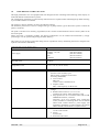
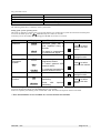
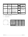
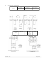
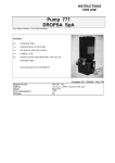
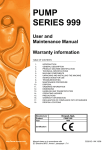
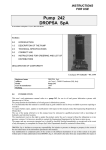
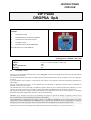
INSTRUCTIONS
FOR USE
VIP Panel
DROPSA SpA
In accordance with point 1.7.4, to I, Dir 98/37 CE
Sections:
0.0
INTRODUCTION
1.0
DESCRIPTION OF THE EQUIPMENT
2.0
TECHNICAL SPECIFICATIONS
3.0
CORRECT USE
4.0
INSTRUCTIONS FOR ORDERING
DECLARATION OF CONFORMITY
Catalogue P/N C2019IE - Wk 35/04
Registered name
Address
Model
Year of manufacture
Marking
0.0
DROPSA SpA
via Croce 1, 20090 Vimodrone (MI), Italy
VIP
1999
CE
INTRODUCTION
This user’s and maintenance manual refers to the VIP panel, used for controlling and monitoring small and medium
sized lubrication systems.
It is recommended that this manual is carefully kept in good condition and is always available to persons requiring to
consult it.
To request further copies, updates or clarification with respect to this manual contact the Engineering Department at
Dropsa SpA.
The use of the panel referred to in this manual must be entrusted to qualified personnel with a knowledge of
hydraulics and electrical systems.
The manufacturer reserves the right to update the product and/or the user’s manual without the obligation to revise
previous versions. It is however, possible to contact the Engineering Department for the latest revision in use.
The equipment should be carefully checked immediately on receipt and in the event of any discrepancy or complaint
the Dropsa SpA Sales Department should be contacted without delay.
DROPSA S.p.A. declines to accept any responsibility for injuries to persons or damage to property in the event of
the non-observance of the information presented in this manual.
Any modification to component parts of the system or the different destination of use of this system or its parts
without prior written authorisation from DROPSA S.p.A. will absolve the latter from any responsibility for injury or
damage to persons and/or property and will release them from all obligations arising from the guarantee.
Instructions for the correct ordering of the required model, and a list of importers, are given in Section 4
1.0
DESCRIPTION OF THE VIP PANEL
This high performance low cost equipment has been designed for the controlling and monitoring of the majority of
small and medium sized lubrication systems.
The configuration parameters are electronically memorised in two separate menus eliminating the problem of having
to pre-set DIP switches or terminals.
The operator’s menu is utilised to set the work and pause timings.
The machine/system menu is used to configure the type of pump and the type of lubrication system to which the
panel is connected.
The panel is also able to be remotely programmed; it has a scanner located under the remote control symbol on the
face of the panel.
When used with a Transmitter module, the desired configuration can be loaded and memorised by simply
positioning it over the symbol and pressing the Enter data key.
This results in a big saving of time when being used on a production line by eliminating the need to configure each
separate control device individually.
Technical and general characteristics:
Characteristic
VIP
Power supply
110/120/220/240V 40/60 Hz
24 VDC – 24 VAC
12 VDC
24V
110/220V
Absorbed power
20 Watts
Temperature of use
-5 °C÷ + 55 °C (+23°F÷131°F)
N.B. the output voltage is the same as the input
Input signals
Output signals
Case
C2019IE – VIP
(Part N° 1639077)
(Part N°1639076)
(Part N°1639094)
(Part N°1639163)
(Part N°1639164)
Max 12V
Pressure switch normally open
Microcontact or magnetic reed contact
Proximity (NPN/PNP)
• Level control:
Max 12V
Contact closes at minimum level
• Impulse counter:
Max. count frequency 10 Hz at 25%
Pump command contact: feed depending on connected
voltage.
• Remote alarm contact NO (NC for 1639101)
Voltage-Free contact, 250V maximum, 1 amp
• Step optional for use of external alarm ONLY FOR
VERSIONS 1639163, 1639164:
Terminal 7 an 8 are a normally open, voltage-free
switch, available as switching device for an external
alarm circuit. Connect fused (+) power supply (not
supplied) to terminal 8. Connect terminal 7 to external
alarm. Ground external alarm to complete circuit.
• External dimensions:
132 X 132 X 160 mm
• Fixing:
95 X 95 mm
• Protection class: IP54
Page 2 of 9
Integrated VIP control
Max. running time
Max. pause time
Max. pause counter
Suspension function
Infra red receiver (accessory)
99 minutes 59 seconds with increments of 10 seconds
99 hours 59 minutes (increments of 1 minute)
Up to 1-2500 impulses (increments of 10 impulses)
Allows the user to interrupt the control functioning
For remote control regulation
The following table shows a summary of the system menu
Setting of the system operating menu
This menu is utilised to configure the type of pump and the type of lubrication system interconnected with the panel.
To access this Menu press the
simultaneously for at least two seconds.
To directly access the modify Times Setting press MODE for at least two seconds
Parameters
Pump
selection
Display
*P N U
*E L E
Description
With a single action
pneumatic pump with a
cycle repetition every 4
seconds.
Operation
Press to select
between the two
values.
The pump is commanded
by a continuous signal.
MODE
Select
SEP
lubrication
system
*S E P
To control systems with
progressive dosers.
PSI
To control systems with
pressure switch.
CLOC
To command pause/work
systems without control.
*T I
*C Y C L
Pause
with
functioning.
Pause
with
functioning.
Press MODE
change function
time
impulse
Press to select
between the two
values.
The Functioning Menu is utilised to regulate the “PUMP OP” cycle time and to regulate the pause functions.
To access the Operator Menu press the MODE key for two seconds;
function accepted by the blinking of the “PUMP ON” LED. Proceed in the sequence shown in the table.
* These functionalities are not available for versions 1639163 and 1639164.
C2019IE – VIP
to
Press to select
between the values.
MODE
Select pause
function
Press MODE
change function
Page 3 of 9
to
Parameters
Cycle time
Display
MM:SS
Pause time
HH:MM
Impulse counter
*1 3 : 2 0
Description
Operation
“pump on” blinking
The desired time is
entered by pressing
the
keys
To access the function
Press the MODE
key for at least two
seconds.
MODE
Indicates the interval
between one lubrication
cycle and the next
Use the
to
regulate the setting.
Indicates the number of
impulses between the
lubrication cycles.
Return to initial menu
MODE
Press the MODE
key for at least two
seconds.
* This functionality is not available for versions 1639163, 1639164.
2.0
TECHNICAL SPECIFICATIONS
2.1
Fixing and dimensions
Part N°
1639076-77-94
1639081-87-89
1639080-84
3056205
1639163
1639164
C2019IE – VIP
A
95 mm
(3.7 in.)
153 mm
(6 in.)
111.5 mm
(4.4 in.)
210 mm
(8.2 in.)
132 mm
(5.2 in.)
B
95mm
(3.7 in.)
222 mm
(8.7 in.)
111.5 mm
(4.4 in.)
160 mm
(6.3 in.)
132
(5.2 in.)
C
Ø 3.5 mm
(Ø 0.14 in.)
Ø 4 mm
(Ø 0.15 in.)
Ø 4 mm
(Ø 0.15 in.)
Ø 4 mm
(Ø 0.15 in.)
Ø 3.5 mm.
(Ø 0.14 in.)
Page 4 of 9
2.2
Electrical system – Technical data
Control
Minimum
Type
Level
With function
Alarms
Pressure switch or
microswitch
contact
12/
+
Proximity
connection
Counting
contact
12/
-
-
+
12/24 V
power supply
and pump
command
connection
C2019IE – VIP
With contact
closed
Time
counting
halted
110/230 V
power supply
and pump
command
connection
Page 5 of 9
3.0
CORRECT USE
3.1
Putting into service
Damage to the power supply cable and housing could result in contact with high voltage live parts and hence be a
danger to life:
♦ carefully check the integrity of the power supply cable and the unit before use;
♦ In the event of there being damage to the power supply cable or the unit, DO NOT put the system into service!;
♦ Replace the damaged power supply cable with a new one;
♦ The unit should be opened and repaired ONLY by qualified personnel;
♦ In order to prevent dangers of electric shock due to direct or indirect contact with live parts it is necessary that
the electrical power supply line is adequately protected by a suitable differential magneto-thermal circuit breaker
with an intervention threshold of 0.03 Ampere and a max. operating time of 1 second.
The breaking capacity of the circuit breaker must be = 4 kA and the nominal current In = ≤ 1 A.
♦ The panel MUST NOT be utilised in environments which are particularly aggressive or explosive/inflammable if
not prepared for this purpose beforehand by the supplier.
♦ Procedure for checking the functioning of the equipment; each time the panel is switched on it performs a selfdiagnosis on the functions and displays any alarms. (see Diagnostic table).
Alarm Codes:
Alarm code
AO1
AO2
*AO3
AO4
(PSI mode only)
AO5
(PSI mode only)
Description
No parameters set
Level Lubrication low
Corrective Action
Set the parameters of the system. See
Setup on pages 3.
Add lubricant to the supply container.
NOTE: This alarm requires that your
system has a low-level switch installed.
The commutation contact in the progressive
system (SEP) has not executed the cycle in
the time set
The system pressure was already high Check pressure switch and replace if
before the start of the cycle.
necessary.
Check to see if system vents properly.
PSI mode: The system did not achieve Check for and correct lubricant leakage
pressure during the specified cycles times. from any loose fittings or from the pump.
1.
2.
3.
4.
5.
Pump ON setting for the system is
too short.
Out of lubricant.
Broken supply line.
Injector malfunction.
Vent valve malfunction.
Adjust setting as appropriate. See Time
Menu on page 4.
Fill reservoir.
Fix or replace.
Replace.
Fix or replace.
* This alarm is not available for versions 1639163, 1639164.
Troubleshooting:
Description
Timer fails to activate
solenoid
Pressure switch fails to
shut down system
C2019IE – VIP
Problem
No power supplied to solenoid.
Solution
Power light off: timer is not receiving power. Verify
connections and verify power supply.
Power light on: verify solenoid connections
Solenoid faulty.
Replace solenoid.
Timer faulty.
Replace timer.
Low Level alarm.
Refill reservoir.
Pressure
switch
incorrectly Verify proper connections.
wired.
Replace pressure switch.
Pressure switch faulty.
Replace timer.
Timer faulty
Page 6 of 9
3.2
Use
1.
2.
3.
4.
3.2.1
verify the settings made;
press the start button of the machine to which the VIP is connected;
verify the starting of the pump;
verify the adequate lubrication of the machine (if doubt exists as to the correct functioning consult the
Engineering Department of Dropsa SpA to request test procedures).
Use of the programmable power supply for recharging the remote control
The VIP/SMART remote control has inside a rechargeable battery to permit it to be used autonomously. Supplied
with the remote control Kit is a programmable power supply unit and a short connection cable.
To recharge the remote control, proceed as follows:
1)
2)
3)
4)
Turn the power supply over so that the 220V plug is uppermost. Take note of the raised “+” and “– “ signs.
On the same side is the socket of the connection cable.
Connect the connection cable to the power supply (using the small plug) paying attention to the polarity;
there are also raised “+” and “–“ signs on the plug which must be matched with those on the power supply
unit.
Turn the unit so that the rotary output voltage selector is visible. Using a screwdriver or a coin, rotate the
selector to position it on “6” – the charging time is 15 hours.
Connect the other end of the connection cable to the remote control (the socket is on the side of the remote
control) and connect the power supply unit to a 220V mains supply socket, maintaining it under charge as
previously described.
WARNING: While the remote control is being charged it is disabled, i.e. it will not function. To enable it to
function, the connection cable must be detached. Do not leave the unit on charge for more than 15/16 hours, or the
internal battery could be damaged.
3.3
Transport and storage
Transport and storage is effected in a cardboard package.
No particular precautions are required except as noted on the package itself.
handling can be effected by one person.
!
Lift the unit with taking account of the right way up indicated on the cardboard carton
!
The machine components can withstand temperatures, during storage, from -20 to +50°C; however, in
order to avoid damage, starting of the machine should occur at a minimum temperature of -5°C.
3.4
Assembly/Disassembly
No assembly operations are envisaged.
For wall mounting ensure adequate space is available (as shown in the installation diagram) to avoid abnormal
postures and possible impacts; four fixing holes are provided as shown in Section 2.
During disassembly operations ensure the power supply is disconnected.
Where the panel is to be scrapped, do not dispose of potentially polluting parts in the environment, following local
regulations for their correct disposal.
At the time of the machine being scrapped it is necessary to remove and destroy the identification plate and all other
relative documents.
3.5
Regulation
The steps to modify the settings of the equipment are shown in Section 1.
VIP Panel (version with control card)
To regulate all the parameters start the pump and press ⇑ + ⇓ for 2 seconds. Then follow the instructions shown in
C2019IE – VIP
Page 7 of 9
the summary table of the system menu.
To modify only the “pump on” and “pause” values, press the MODE key for 2 seconds.
Remote control
To modify the control parameters using the infrared:
a)
check that the panel is functioning
b)
position the programmer on the remote control symbol and press “transmit” on the programmer.
The control emits a serious of flashes per approx. 5 seconds to confirm that the data has been correctly received.
3.6
Maintenance
!
Locate the machine in conditions which facilitate easy access.
The VIP device does not require any maintenance.
3.7
Repair
No repair operations are envisaged; in case of malfunctioning contact the Engineering Department of DROPSA
S.p.A.
3.8
Dangers present in use
The verification of conformity with the relevant EN 60204-1 electrical safety requirements and regulations is
effected by means of the compilation of a check list which has been pre-prepared and is contained in the technical
file.
4.0
INSTRUCTIONS FOR ORDERING AND LIST OF DISTRIBUTORS
VERSIONS
Part number
1639076
1639077
1639080
1639084
1639088
1639081
1639087
1639089
1639094
1639097
3056205
1639163
1639164
Description
VIP 24V Box version
VIP 110/230V Box version
VIP 24 DC Version with panel mounted
VIP 110/230V Version with panel mounted
Remote transmission module
VIP 220V Single phase in steel case
VIP 380V – 50 Hz 3-phase in steel case
VIP 500V – 50 Hz 3-phase in steel case
VIP 12V Box version
VIP 220V single phase/3-phase
VIP 115/230V – 50/60 Hz with 50 W power and 24 V transformer
VIP 24V
VIP 110/220V
Replacement parts : No replacement parts are provided. Refer any repair requirements to manufacturer.
C2019IE – VIP
Page 8 of 9
CE Declaration Of Conformity
Manufacturer:
DROPSA SpA
Company
Via Croce, 1 - 20090 Vimodrone (MI), Italy
Address
+39 02 250791
Telephone
It is certified that:
The machine: VIP Panel Ver. 076 – 077 – 080 – 084 – 088 – 081 – 087 – 089 – 097 – 163 -164 - 3056205
∗ is manufactured in conformity with the DIRECTIVE OF THE COUNCIL OF THE EUROPEAN COMMUNITY
concerning the harmonisation of member states legislation relative to Low Voltage and Electromagnetic
compatibility (EMC (89/336/CEE) and BT (73/23/CEE) and relative amendments.
∗ is manufactured in accordance with the following standards and harmonised technical specifications:
EN 292/1, EN 292/2, EN 50081-2, EN 50082-2, CEI EN 60204-1.
Technical Manager
Product Manager
DROPSA SpA
Company
Ing. Walter Divisi
Name
- Vimodrone (MI) - Italy
January 1999
Date
Signature
DROPSA SPA DISTRIBUTORS
ITALY
Dropsa SpA
t.(+39) 02-250791
f.(+39) 02-25079767
U.S.A.
Dropsa Corporation
t.(+1) 586-566-1540
f.(+1) 586-566-1541
BRAZIL
Dropsa
t.(+55) 011-563-10007
f.(+55) 011-563-19408
AUSTRALIA
Dropsa Australia Ltd.
t.(+61) 02-9938-6644
f.(+61) 02-9938-6611
SPAIN
Polydrop, S.A.
t.(+34) 93-260-22-50
f.(+34) 93-260-22-51
U.K.
Dropsa (UK) Ltd
t.(+44) 01784-431177
f.(+44) 01784-438598
GERMANY
Dropsa Gmbh
t.(+49) 0211-394-011
f.(+49) 0211-394-013
FRANCE
Dropsa Ame
t.(+33) 01-3993-0033
f.(+33) 01-3986-2636
C2019IE – VIP
Page 9 of 9