1
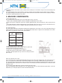
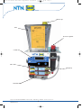
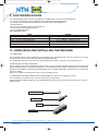
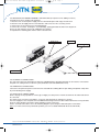
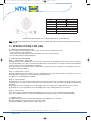
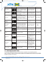
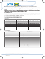
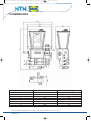
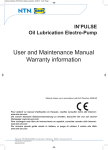
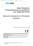
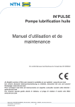
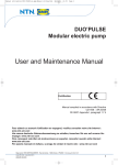
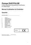
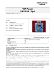
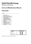
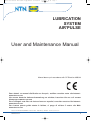
Manuel utilisation AIR PULSE en.qxp:Manuel utilisation
13/12/10
14:52
Page 1
LUBRICATION
SYSTEM
AIR’PULSE
User and Maintenance Manual
Manual drawn up in accordance with CE Directive 2006/42
Pour obtenir ce manuel d'utilisation en français, veuillez consulter notre site Internet :
www.ntn-snr.com
Um unsere deutsche Gebrauchsanweisung zu erhalten, besuchen Sie uns auf unserer
Homepage: www.ntn-snr.com
Para conseguir este libro de instrucciones en español, consultar nuestro sitio Internet :
www.ntn-snr.com
Per ricevere questa guida utente in italiano, si prega di visitare il nostro sito Web:
www.ntn-snr.com
Siège social : NTN-SNR ROULEMENTS - Rue des Usines - 74000 Annecy - FRANCE - RCS Annecy B 325 821 072
Code APE 2815Z - Code NACE 28.15
www.ntn-snr.com
1
Manuel utilisation AIR PULSE en.qxp:Manuel utilisation
1. TABLE OF CONTENTS
1. Table of contents
2. Introduction
3. Product-machine identification
4. General description,
5. Machine components
6. Technical specifications
7. Handling and transportation
8. Precautions in use
9. Contraindications
2. INTRODUCTION
13/12/10
p.2
p.2
p.2
p.2
p.3
p.5
p.5
p.5
p.6
14:52
Page 2
10. Unpacking and installing the machine
11. Instructions for use
12. Troubleshooting
13. Maintenance procedure
14. Disposal
15. Ordering information
16. Dimensions
17. Warranty information
18. Declaration of conformity
p.6
p.8
p.9
p.10
p.11
p.11
p.12
p.13
p.14
This user and maintenance manual refers to the AIR’PULSE air/oil lubrication system.
This manual should be conserved in such a way that it remains undamaged over time and is readily available to personnel
needing to consult it.
The manufacturer reserves the right to update the product and/or the user and maintenance manual without the obligation
to revise previous versions.Further copies of this manual, updates or clarifications can be obtained by directly contacting
Experts & Tools at NTN-SNR Roulements, or to consult our web site at www.ntn-snr.com.
The use of the equipment referred to in this manual must be entrusted to qualified personnel with a basic knowledge of
mechanics, hydraulics and electrical systems.
It is the responsibility of the installer to use tubing suitable for the system; the use of inadequate tubing can cause
problems with the pump, injury to persons and create pollution.
Loosening of connections can cause serious safety problems; carry out a check before and after installation and, if
necessary retighten them.
Never exceed the maximum working pressure values permitted for the panel and the components connected to it.
Before any maintenance or cleaning operation disconnect the power supply, close off the airsupply and discharge the
pressure from inside the equipment and the tubing connected to it.
Do not subject the panel, the connections, the tubing or parts under pressure to violent impacts; damaged tubing or
connections are dangerous and should be immediately replaced.
After long periods of inactivity check air tightness of all parts subjected to pressure.
Personnel must use personal protection equipment, clothing and tools adequate for the location and the use of the panel
both during its operation and during maintenance operations.
The panel, and any accessories mounted on it, should be carefully checked immediately on receipt and in the event of
any discrepancy or complaint the NTN-SNR Roulements Sales department should be contacted without delay.
NTN-SNR Roulements declines to accept any responsibility for injuries to persons or damage to property in the event of
the non-observance of the information presented in this manual.
Any modification to component parts of the system or the different destination of use of this system or its parts without
prior written authorization from NTN-SNR Roulements will absolve the latter from any responsibility for injury to persons
and/or damage to property and will release them from all obligations arising from the guarantee.
3. PRODUCT-MACHINE IDENTIFICATION
A yellow plate showing the product code, the supply voltage and the basic characteristics is mounted on the front of the
oil tank.
4. GENERAL DESCRIPTION
The AIR’PULSE pump is to be used on machine tool spindles.
Designed for high performance at a low cost, it is distinguished by its compactness.
The system is composed of a central unit which controls and manages the entire system.
The central unit regulates and controls the functioning of the modular dosers and mixers,
which are composed of pneumatically controlled mini-pumps and mixer bases. The minipumps can be fitted with a series of spacers in order to vary the flow rate so as to cover a wide range of needs.
2
Siège social : NTN-SNR ROULEMENTS - Rue des Usines - 74000 Annecy - FRANCE - RCS Annecy B 325 821 072
Code APE 2815Z - Code NACE 28.15
www.ntn-snr.com
Manuel utilisation AIR PULSE en.qxp:Manuel utilisation
13/12/10
14:52
Page 3
Integrated inside the mixer base is a flow control, which is used by the central unit to verify the correct functioning of the
equipment.
The modular design of the system makes it extremely versatile; up to a maximum of 8 mixer bases can be installed.
The high technology used in this system permits a total control of the lubrication combined with a simplicity of installation without requiring superfluous connections.
5. MACHINE COMPONENTS
Central AIR’PULSE Unit
The central unit of the lubrication system is composed of the three elements:
• A Tank, made of transparent plastic material, compatible with lubricants on the market.
• An air control system composed of a pressure regulator, applied laterally, and a solenoid valve, which can block the air
flow.
• The AIR’PULSE panel manages and controls the entire lubrication process: the time intervals, the lubrication flow rate,
the air pressure and the oil level. In addition it provides for priming cycles (air venting).
Pneumatic Mini-pump
The mini-pumps employed are particularly small and are installed on the mixer bases. They can be fitted with a range of
spacers which serve to vary the flow rate. The following table details how to recognize these and indicates the relative
part numbers. To change the spacers proceed as follows:
NUMBER
FLOW RATE
OF
(mm3/cycle)
NOTCHES
1
30
4
7
3
15
1. Unscrew and remove the brass cap (A).
2. Rotate shaft (B) until the hole (C) aligns with the relative slot.
3. Insert a Ø2 mm tommy bar in hole (C).
4. Unscrew hex. nut (D) using a 5,5 mm spanner.
5. Slide off the spacer (E) and replace it with the required one.
6. Replace and fully tighten nut (D), remove the tommy bar and replace cap (A).
Mixer base with flow rate sensor
In the mixer base there is an integrated lubrication detector system with a self-setting sensor. This sensor does not require to be regulated or calibrated as it automatically adapts to the functioning conditions and the type of lubricant.
The detection system is interfaced, by means of an electrical connection completely integrated into the mixer base, with
the AIR’PULSE panel mounted on the central unit. Where an anomaly occurs this is detected by the central unit, which
signals the error.
The functioning is also indicated by an LED mounted on the base itself.
When the AIR’PULSE starts a lubrication cycle, the LED located on the mixer base illuminates (ON) until the end of the
lubrication cycle. During the pause the LED is not illuminated (OFF).
3
Siège social : NTN-SNR ROULEMENTS - Rue des Usines - 74000 Annecy - FRANCE - RCS Annecy B 325 821 072
Code APE 2815Z - Code NACE 28.15
www.ntn-snr.com
Manuel utilisation AIR PULSE en.qxp:Manuel utilisation
13/12/10
14:52
Page 4
Oil filler cap
Tank
Pressure regulator
Central unit
Mixer base
Mini-pump
Solenoid valve
4
Siège social : NTN-SNR ROULEMENTS - Rue des Usines - 74000 Annecy - FRANCE - RCS Annecy B 325 821 072
Code APE 2815Z - Code NACE 28.15
www.ntn-snr.com
Manuel utilisation AIR PULSE en.qxp:Manuel utilisation
13/12/10
14:52
Page 5
6. TECNICAL SPECIFICATIONS
Power supply voltage
CHARACTERISTICS
24 V DC
110 V AC
10 W
5 - 8 bar
Remote alarm contact: max. 250V 1A NO/NC
-5°C to +55°C
90% max.
IP-44
Oil
32 to 220 cSt
-20°C to +65°C
Absorbed power
Air supply pressure
Output signals
Working temperature
Working humidity
Protection level
Admissible lubricants
Oil viscosity at working temp.
Conservation temperature
WARNING : DO NOT SUPPLY THE MACHINE WITH VOLTAGES OR PRESSURES OTHER
THAN THOSE INDICATED ON THE SPECIFICATION PLATE.
7. HANDLING AND TRANSPORTATION
Prior to shipment AIR’PULSE lubrication panels are carefully packed in a cardboard carton. During transportation and
storage maintain the equipment the right way up as indicated on the carton.
On receipt, check that the packaging is not damaged and store the equipment in a dry place.
Given the lightness of the unit, lifting devices are not required for its handling. The box is fitted with suitable handling
devices.
8. PRECAUTIONS IN USE
It is necessary to carefully read the warnings and the risks involved in using the lubrication panel. The operator must
understand the functioning of the unit by studying the user’s manual.
Electric currents
No intervention must be attempted on the equipment without first having disconnected the electrical power supply and
ensuring that it cannot be reconnected during the intervention.
All installed equipment, electrical, electronic, tank and base structure, must be connected to the ground line utilizing the
terminals fitted to each component.
Flammability
The oil employed in the lubrication circuit is not normally flammable. It is nonetheless indispensable to take every
precaution against the oil coming into contact with very hot parts or open flames.
Pressure
Prior to any intervention on the equipment ensure that pressure is released from all branches of the lubrication circuit.
Failure to do this could result in oil being discharged under pressure where connections or components are disassembled
Noise
The AIR’PULSE lubrication panel does not emit excessive noise, remaining below 70dB(A).
WARNING: before carrying out the replacement of the mini-pumps, empty the tank of lubricant.
5
Siège social : NTN-SNR ROULEMENTS - Rue des Usines - 74000 Annecy - FRANCE - RCS Annecy B 325 821 072
Code APE 2815Z - Code NACE 28.15
www.ntn-snr.com
Manuel utilisation AIR PULSE en.qxp:Manuel utilisation
13/12/10
14:52
Page 6
9. CONTRAINDICATIONS
The AIR’PULSE panel does not have any particular contraindications except for the following points:
• The operator coming into contact with fluid due to breakage/opening of supply tubing.
The operator must be furnished with suitable personal protection clothing/equipment.
• Abnormal posture.
Take note of the indications shown in paragraph 10.2.
• Contact with oil during filling/maintenance.
• Use of unsuitable lubricants.
Main inadmissible fluids.
Fluid
Danger
Lubricants with abrasive additives
Lubricants with silicon based additives
Petrol – solvents – flammable liquids
Corrosive products
Water
Food substances
High wear rate of contacted parts
Seizure of the pump
Fire – explosion – damage to seals
Corrosion of the pump– injury to persons
Oxidation of the pump
Contamination of the substances themselves
10. UNPACKING AND INSTALLING THE MACHINE
10.1 UNPACKING
Once a suitable location has been identified for the installation, open the package and remove the equipment. Check that
the AIR’PULSE has not sustained damage during transport and storage.
The packaging material does not require any special disposal precautions, not being in any way dangerous or.
10.2 MOUNTING THE AIR’PULSE PANEL
Provide adequate space for the installation, leaving a minimum room of 100 mm around the panel. Mount the AIR’PULSE
panel at shoulder height to avoid unnatural posture or the possibility of obscuring the control panel or of sustaining
impacts. Do not install the AIR’PULSE in particularly aggressive or explosive/flammable environments or on components
subject to vibration.
Only use the supplied mounting bracket with N° 2 holes for Ø6 mm bolts.
10.3 MOUNTING THE MINI-PUMPS ON THE MIXER BASES (for replacement or adding new ones)
The mini-pumps are mounted on the mixer bases using two securing screws.
Particular attention should be paid to the correct positioning of the o-rings between the minipump and the mixer base (see
diagram below).
Securing screws
Mini-pump
Seals
Mixer base
6
Siège social : NTN-SNR ROULEMENTS - Rue des Usines - 74000 Annecy - FRANCE - RCS Annecy B 325 821 072
Code APE 2815Z - Code NACE 28.15
www.ntn-snr.com
Manuel utilisation AIR PULSE en.qxp:Manuel utilisation
13/12/10
14:52
Page 7
10.4 MOUNTING THE DOSER ASSEMBLY ON THE PUMP (for replacement or adding new ones)
To install a new mixer unit proceed as follows:
1. Disconnect the electrical power supply from the AIR’PULSE panel and empty the tank of oil.
2. Disconnect the air supply from the solenoid valve and remove the three securing screws.
3. Unscrew the screws which secure the blanking plate.
4. Connect the new base, inserting the electrical bridge, paying particular attention to the alignment.
Secure the unit using the two screws supplied for the purpose.
5. Reposition the blanking plate and the relative solenoid valve.
Grub screw
Electrical bridge
Seals
Base Assembly
Securing screws
10.5 HYDRAULIC CONNECTIONS
The only connection to be undertaken is that of the individual pumps, provided with push-in connections, to the lubrication point. The tubing must be in Ø4 mm nylon (obtainable from NTN-SNR Roulements).
10.6 PNEUMATIC CONNECTIONS
Connect the air input to the push-in connector of the solenoid valve utilizing Ø6 mm nylon tubing, and provide a stop valve
to permit shutting off the supply.
10.7 ELECTRICAL CONNECTIONS
Before carrying out any operation check the type of supply necessary for the machine as shown on the label located near
the connector.
The panel is to be interconnected with the emergency stop switch of the machine it is serving.
For 110 V supply the user must protect the installation with a magneto-thermic differential IN switch max. 2 Amp, Idn 0.03
Amp. For safety purposes the Alarm contact (NO/NC) must be connected.
For the electrical connections refer to the following diagram representing the lubrication panel connections.
Note: The female connector is purchased separately (reference LUBSO AIRPULSE PLUG & CABLE 2M)
7
Siège social : NTN-SNR ROULEMENTS - Rue des Usines - 74000 Annecy - FRANCE - RCS Annecy B 325 821 072
Code APE 2815Z - Code NACE 28.15
www.ntn-snr.com
Manuel utilisation AIR PULSE en.qxp:Manuel utilisation
13/12/10
14:52
Page 8
Pin/Wire
1
2
3
4
5
6
24 V version 110 V version
0V
24 VDC
/
/
110 VAC
NC Alarm
COMMON Alarm
NO alarm
Ground
Connect and Cable assembly 2 mt : LUBSO AIRPULSE PLUG & CABLE 2M
N.B.: After all connections have been completed ensure the tubing and cables are protected from impacts and are suitably secured.
11. INSTRUCTIONS FOR USE
11.1 STARTING THE AIR’PULSE PANEL
Before using the AIR’PULSE panel, it is necessary to carry out some preliminary checks:
- check the integrity of the equipment
- check that the electrical and pneumatic connections have been effected correctly
- enter the data inside the AIR’PULSE panel
11.2 METHOD OF FUNCTIONING
Stage 1 – Initial function – Prime mode
Simultaneously press the MODE and ↓ keys for at least 10 seconds. The pump goes into the Prime mode, executing a
series of lubrication cycles, with 1 second of lubrication and 1 second of pause, necessary to eliminate all air bubbles
from the system, for an overall duration of 10 minutes.
At the end of this cycle, the Panel effects one lubrication cycle and carries out a verification of the lubrication. If there are
no alarms it proceeds to Stage 3.
Stage 2 – Initial function - Set-up
Press the MODE key for 10 seconds to enter the configuration menu. All the basic functions necessary for the correct
functioning of the equipment are entered during this Set-up function.
To regulate see the paragraph on regulation.
Stage 3 – Normal function
On switching on the cycle is automatically activated. During the pause time the display shows alternately the time
remaining of the cycle and the mixer air pressure. At the same time the LEDs at the side of the display are illuminated
alternately.
By pressing the ↑ key it is possible to freeze the display of the mixer air pressure reading until the key is released.
By pressing the ↓ key it is possible to freeze the display of the timer reading until the key is released.
Stage 4 – Alarm function
In the alarm mode the display starts blinking displaying the error code (see the “troubleshooting” paragraph).
When the conditions have been restored, the RESET button must be pressed to return to normal functioning.
11.3 REGULATION
To regulate all the parameters, start the pump and press the MODE key for 5 seconds.
Subsequently follow the instructions given in the table below.
Pressing the MODE key passes from one option to the next.
8
Siège social : NTN-SNR ROULEMENTS - Rue des Usines - 74000 Annecy - FRANCE - RCS Annecy B 325 821 072
Code APE 2815Z - Code NACE 28.15
www.ntn-snr.com
Manuel utilisation AIR PULSE en.qxp:Manuel utilisation
Parameters
Cycle control
time
Display
Pump recharge
time
Pausecycle
Inversion of
solenoid
command
N° of control
elements
Max. air
Min. air
13/12/10
14:52
Page 9
Description
Operation
The max. time is set within which
the delivery of lubricant must be
Enter the desired values
confirmed. The range of regulation using the ↑ and↓ keys
is 00-60 seconds
Pause time for recharging the
pump. The range of regulation is
0.0-9.9 seconds.
Enter the desired values
using the ↑ and↓ keys
Default
5s
1,5 s
Interval of time between one lubrication cycle and the next. The
count commences when the deli- Enter the desired values
Selon l’utilisateur
using the ↑ and↓ keys
very of lubricant is confirmed.
Range of regulation is 00.00-99.59
minutes.
Relay function; 1 for NC, 0 for NO.
Do not alter
1
Number of elements installed with
flow control. If the value 0 is set,
before entering in pause (pause
Enter the desired values
Min. 1
time), all the timeout time must
using the ↑ and↓ keys
Max. 8
pass. Range of regulation 0-99
elements.
Max. limit of mixer air pressure.
Entering the value 0 the alarm is di- Enter the desired values
Selon l’utilisateur
sabled. Range of regulation 0.0-7.0 using the ↑ and↓ keys
bar
Min. limit of air pressure. Range of
Enter the desired values
regulation 0.0-7.0 bar.
Selon l’utilisateur
using the ↑ and↓ keys
Entering the value 0 an
error is displayed but the
VIP4Air continues to
operate.
Entering the value 1 an
error is signaled and the
equipment stops.
Minimum oil
level
Alarm function for minimum oil
level.
System start
pre-cycle
Enter the desired values
using the ↑ and ↓ keys
Number of start cycles for system
bearing in mind that the
pre-lubrication. Range of regulation
value of cycles entered
00-60.
must be double that of
the desired value.
6
Cycles of fault
Number of consecutive fault cycles Enter the desired values
needed for an alarm.
using the ↑ and ↓ keys.
2
12. TROUBLESHOOTING
1
The following is a diagnostic table giving the main anomalies, the probable causes and possible solutions.
If, after consulting this diagnostic table, the problem remains unresolved, do not attempt to disassemble the machine
looking for faults, but contact the Experts & Tools Department at NTN-SNR Roulements with an as fully detailed
description as possible of the anomaly.
9
Siège social : NTN-SNR ROULEMENTS - Rue des Usines - 74000 Annecy - FRANCE - RCS Annecy B 325 821 072
Code APE 2815Z - Code NACE 28.15
www.ntn-snr.com
Manuel utilisation AIR PULSE en.qxp:Manuel utilisation
13/12/10
14:52
Page 10
DIAGNOSTIC TABLE FOR THE AIR’PULSE PANEL
ALARM SIGNAL
A-PF
Pump cycle
CDESCRIPTION OF DEFECT
CAUSE/INTERVENTION
o The flow sensor has not
detected the correct dose.
o Presence of air in the circuit causing
incorrect delivery. Carry out Priming
cycle.
o Pump defective. Carry out Priming
verifying the delivery of lubricant at the
outlet.
o Flow sensor defective. Check the
sensor electrical connections or replace
it.
o Check the oil level in the tank.
o Air pressure too high
A-AL
Air low
o Check the pressure on the display and
regulate it on the external reducer. To
facilitate the operation press and hold
down the ↑ key to freeze the air
pressure display. The alarm depends on
the value entered during set-up.
o Air pressure too low
A-LL
Oil level
o Check the pressure on the display and
regulate it on the external reducer. To
facilitate the operation press and hold
down the ↑ key to freeze the air
pressure display. The alarm depends on
the value entered during set-up.
o Low oil level
A-PE
Pre-cycle
o Add oil to the tank. Warning: if the low
oil level alarm function is not enabled,
there will be an alarm signal but the
equipment will not be stopped.
o No pre-cycle reading
o Presence of air in the circuit causing
incorrect delivery. Carry out Priming
cycle.
o Pump defective. Carry out Priming
verifying the delivery of lubricant at the
outlet.
o Flow sensor defective. Check the
sensor electrical connections or replace
it.
o Check the oil level in the tank.
A-AH
Air hight
(could be plugged air/oil line)
(could be broken air/oil line)
13.MAINTENANCE PROCEDURE
The pump has been designed and constructed so as to reduce maintenance to a minimum.
To simplify maintenance it is recommended that the equipment be mounted in an easily reached location (see paragraph
7.2).
Periodically check the tubing connections for leaks. Always maintain the equipment in a clean condition in order that any
leaks will be immediately evident. When necessary replace the oil filling filter.
10
Siège social : NTN-SNR ROULEMENTS - Rue des Usines - 74000 Annecy - FRANCE - RCS Annecy B 325 821 072
Code APE 2815Z - Code NACE 28.15
www.ntn-snr.com
Manuel utilisation AIR PULSE en.qxp:Manuel utilisation
13/12/10
14:52
Page 11
Periodically empty the pressure regulator condensate trap by rotating the small red valve located at its base.
The machine does not require any special tools for carrying out checks and/or maintenance tasks. It is recommended
that suitable tools and personal protection clothing (gloves) are used in accordance with Legislative Decree 81/2008
(Safety at Work legislation), and that they are in good condition in order to avoid injury to persons and damage to the
machine.
ENSURE THAT ELECTRICAL, PNEUMATIC AND HYDRAULIC SUPPLIES ARE DISCONNECTED BEFORE UNDERTAKING ANY MAINTENANCE TASKS.
14.DISPOSAL
During the maintenance of the machine, or in the event of its being scrapped, do not discard polluting components in the
environment. Refer to local regulations for their correct disposal. At the time of final disposal of the machine it is necessary to destroy the identification plate and all other documentation.
15.ORDERING INFORMATION
VERSIONS
Number of mini pumps
AIR’PULSE - 24 VDC
AIR’PULSE - 110 VAC
1
LUBSO AIRPULSE 24V 1 JET
LUBSO AIRPULSE 110V 1 JET
3
LUBSO AIRPULSE 24V 3 JET
LUBSO AIRPULSE 110V 3 JET
2
4
5
6
7
8
ACCESSOIRES
LUBSO AIRPULSE 24V 2 JET
LUBSO AIRPULSE 24V 4 JET
LUBSO AIRPULSE 24V 5 JET
LUBSO AIRPULSE 24V 6 JET
LUBSO AIRPULSE 24V 7 JET
LUBSO AIRPULSE 24V 8 JET
PART REFERENCE
LUBSO AIRPULSE RESERVOIR
LUBSO AIRPULSE FILTER
Complete tank
LUBSO AIRPULSE 110V 2 JET
LUBSO AIRPULSE 110V 4 JET
LUBSO AIRPULSE 110V 5 JET
LUBSO AIRPULSE 110V 6 JET
LUBSO AIRPULSE 110V 7 JET
LUBSO AIRPULSE 110V 8 JET
DESCRIPTION
Filter for filling oil
LUBSO AIRPULSE SOLENOID VALVE 24VDC Solenoid valve 24 VDC
LUBSO AIRPULSE SOLENOID VALVE 110 VAC Solenoid valve 110 VAC
LUBSO AIRPULSE MIXER BASE
Mixer base with flow control
LUBSO AIRPULSE WASHER 7MM3
Washer for 7 mm3
LUBSO AIRPULSE PNEUMATIC MINI PUMP
LUBSO AIRPULSE WASHER 15MM3
LUBSO AIRPULSE WASHER 30MM3
LUBSO HOSE 4MM 25M
LUBSO HOSE 6MM 25M
LUBSO AIRPULSE POWER SUPPLY 24VDC
LUBSO AIRPULSE POWER SUPPLY 110VAC
LUBSO AIRPULSE PLUG & CABLE 2M
Mini-pump, pneumatic, complete with set of washers + 2 screws
Washer for 15 mm3
Washer for 30 mm3
Tube, flexible Ø4
Tube, flexible Ø6
Box, connection, power supply 24 V dc
Box, connection, power supply 110 V ac
Connector + connection cable (2 m)
11
Siège social : NTN-SNR ROULEMENTS - Rue des Usines - 74000 Annecy - FRANCE - RCS Annecy B 325 821 072
Code APE 2815Z - Code NACE 28.15
www.ntn-snr.com
Manuel utilisation AIR PULSE en.qxp:Manuel utilisation
13/12/10
14:52
Page 12
TUBE
TUBE
16.DIMENSIONS
Number of mini pumps
1
2
3
4
5
6
7
8
Height A (mm)
331
359
387
415
448
471
499
527
12
Siège social : NTN-SNR ROULEMENTS - Rue des Usines - 74000 Annecy - FRANCE - RCS Annecy B 325 821 072
Code APE 2815Z - Code NACE 28.15
www.ntn-snr.com
Weight (kg)
3.8
4.3
4.8
5.3
5.8
6.3
6.8
7.3
Manuel utilisation AIR PULSE en.qxp:Manuel utilisation
13/12/10
14:52
Page 13
17.WARRANTY INFORMATION
All products manufactured and marketed by NTN-SNR Roulements are warranted to be free of defects in material or
workmanship for a period of at least 12 months from date of delivery.
Extended warranty coverage applies as follows if complete system installation by NTN-SNR Roulements: 12 Months.
If a fault develops, notify NTN-SNR giving:
a complete description of the alleged malfunction
the part number(s)
date of delivery
date of installation
operating conditions of subject product(s)
NTN - SNR Roulements reserves to right to charge an administration fee if the product(s) returned are found to be not
defective.
This limited warranty does not cover any products, damages or injuries resulting from misuse, neglect, normal expected
wear, chemically caused corrosion, improper installation or operation contrary to factory recommendation. Nor does it
cover equipment that has been modified, tampered with or altered without authorization.
Consumables and perishable products are excluded from this or any other warranty.
No other extended liabilities are states or implied and this warranty in no event covers incidental or consequential
damages, injuries or costs resulting from any such defective product(s).
The use of NTN-SNR product(s) implies the acceptance of our warranty conditions. Modifications to our standard warranty
must be in made in writing and approved by NTN-SNR Roulements.
13
Siège social : NTN-SNR ROULEMENTS - Rue des Usines - 74000 Annecy - FRANCE - RCS Annecy B 325 821 072
Code APE 2815Z - Code NACE 28.15
www.ntn-snr.com
Manuel utilisation AIR PULSE en.qxp:Manuel utilisation
13/12/10
14:52
Page 14
18.DECLARATION OF CONFORMITY
DECLARATION OF CONFORMITY
NTN-SNR Roulements, registered in Annecy, rue des Usines,
CERTIFIES :
that the machine named AIR’PULSE pump
has been constructed in conformity with the DIRECTIVES OF THE COUNCIL OF THE EUROPEAN
COMMUNITY on the standardization of the legislations of member states:
- 2006/42
Machinery Directive
---------------------------------------------------------------------------------------------------------------------------------Annecy, July 2010
NTN-SNR Roulements
Christophe Oddoux,
General Manager Experts & Tools
Christophe Benier,
Product Manager Experts & Tools
14
Siège social : NTN-SNR ROULEMENTS - Rue des Usines - 74000 Annecy - FRANCE - RCS Annecy B 325 821 072
Code APE 2815Z - Code NACE 28.15
www.ntn-snr.com
Manuel utilisation AIR PULSE en.qxp:Manuel utilisation
13/12/10
14:52
Page 15
Web site: www.NTN-SNR.com - E-mail: [email protected]
LUB SOLUTIONS : The Products and Services offer designed to bring you lubrication
solutions. Specifically selected for your different applications, a choice of lubricants is offered
as well as a full range of reliable systems to dispense them with precision on each mechanical
organ.
LUB SOLUTIONS are above all experts to support you while setting up lubrication systems
adapted to your environment. From advices to specify your needs to the implementation of
your lubrication system, including their manufacturing, rely on our experts to bring you the
right solution.
Experts & Tools offer also maintenance tools, specifically designed for bearing fitting and
removal.
Should you require more info, please ask for our "Maintenance tool catalogue" or visit our
Internet website www.ntn-snr.com
“Bringing you a complete tools and services solution for your bearings, suited to your
application, size and resources.”
15
Siège social : NTN-SNR ROULEMENTS - Rue des Usines - 74000 Annecy - FRANCE - RCS Annecy B 325 821 072
Code APE 2815Z - Code NACE 28.15
www.ntn-snr.com