1
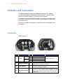
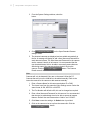
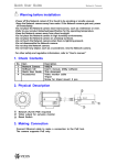
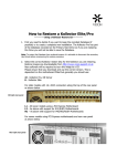
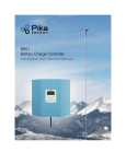
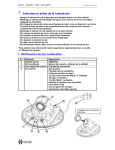
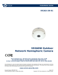
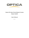
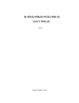
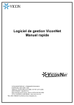
Setup Guide
XX252-30-00
Setup Guide for V9360-1
Series Cameras
Vicon Industries Inc.
Tel: 631-952-2288 Fax: 631-951-2288 Toll Free: 800-645-9116
24-Hour Technical Support: 800-34-VICON (800-348-4266) UK: 44/(0) 1489-566300
Vicon Industries Inc. does not warrant that the functions contained in this equipment will meet your requirements or that the
operation will be entirely error free or perform precisely as described in the documentation. This system has not been designed
to be used in life-critical situations and must not be used for this purpose.
www.vicon-security.com
Document Number: 8009-8252-30-00
Product specifications subject to change without notice.
Issued: 315
Copyright © 2015 Vicon Industries Inc. All rights reserved.
Setup V9360-1 Hemispheric Cameras
|
1
Connecting the V9360-1 Hemispheric
Cameras
This guide provides a quick installation guide and a step-by-step procedure
to set up V9360-1 IP Hemispheric Cameras for use with various openstandard Video Management Systems (VMS), including Vicon’s ViconNet®
Video Management System. When using the Vicon system, it assumes an
understanding of ViconNet and the camera. Refer to the ViconNet and
camera manuals for detailed information.
The camera has a DeviceSearch (Discovery tool) that provides a way for it to
be found on the network. After it has been added to the network, the camera
is then connected to the VMS.
Go to Vicon’s website, www.vicon-security, to find full installation and user
manuals and the DeviceSearch tool.
2
|
Setup V9360-1 Hemispheric Cameras
Installation and Connections
The camera package includes all the hardware necessary for installation,
including terminal blocks. Additionally, a PC and monitor, a Network Switch
and an RJ-45 network cable (1 for each device) are required.
PoE switches that are IEEE802.3af compliant can power the camera directly.
For devices connected to a non-PoE switch, a power adapter is required with
the terminal block.
Refer to the complete User Manual for detailed instruction on installation and
connections.
Connections
Indoor Version
No.
Connector
DC 12V
1
Power
AC 24V
Pin
1
2
1
2
-
2
RJ-45
3
Alarm & Audio I/O
-
4
Default Button
-
5
microSD Card Slot
-
Definition
Remarks
DC 12V
Reserved
Power connection
AC 24V 1
AC 24V 2
For network and PoE connections
Please refer to the Alarm & Audio I/O in the table
under All-in-One Cable (Optional).
Press the button with a proper tool for at least 20
seconds to restore the system.
Insert the microSD card (customer-supplied) into the
card slot to store videos and snapshots. Do not
remove the microSD card when the camera is
powered on.
Setup V9360-1 Hemispheric Cameras
|
3
All-in-One Cable (Optional)
No.
Connector
1
Alarm & Audio I/O
2
Audio I/O
3
Alarm I/O
(4-Pin Terminal Block)
Pin
1
2
3
4
5
6
7
8
Pink
Green
1
2
3
4
Definition
Alarm Out +
Alarm Out –
Alarm In +
Alarm In –
Audio Out
GND
Audio In
Audio In
Audio Out
Alarm In –
Alarm In +
Alarm Out –
Alarm Out +
Remarks
Alarm connection/Two-way
audio transmission
Two-way audio transmission
Alarm connection
4
|
Setup V9360-1 Hemispheric Cameras
Outdoor Version Function Cables
No.
Connector
1
Audio I/O
2
Power (DC 12V / AC 24V)
(2-Pin Terminal Block)
3
Alarm I/O
(4-Pin Terminal Block)
4
5
GND
RJ-45
Pin
Pink
Green
Black
Red
1
2
3
4
-
Definition
Remarks
Audio In
Two-way audio transmission
Audio Out
AC 24V –
DC 12V –
Power connection
AC 24V +
DC 12V +
Alarm In –
Alarm In +
Alarm connection
Alarm Out –
Alarm Out +
GND
Ground connection
For network and PoE connections
microSD Card Slot / Default Button
The camera’s microSD card slot and default button are inside the camera cover.
To use them, loosen the two security screws of the camera with the supplied
tool and detach the cover.
Insert the microSD card (customersupplied) into the card slot to store
videos and snapshots.
Press the default button with proper
tool for at least 20 seconds to restore
the system to factory defaults.
Setup V9360-1 Hemispheric Cameras
|
5
Power Connection
Please use a DC 12V/AC 24V power adaptor and plug it to the camera and
the power outlet. Alternatively, users can use an Ethernet cable and connect
it to the RJ-45 connector of the camera and a Power Sourcing Equipment
(PSE) switch.
NOTE: If PoE is used, verify your power source.
Ethernet Cable Connection
Connect one end of the Ethernet cable to the RJ-45 connector of the camera,
and plug the other end of the cable to the network switch or PC.
NOTE: In some cases, Ethernet crossover cable might be needed when connecting
the camera directly to the PC.
NOTE: Check the status of the link indicator and activity indicator LEDs. If the LEDs
are unlit, check the LAN connection.
Green Link Light indicates good network connection.
Orange Activity Light flashes for network activity indication.
Before Login to the Camera
A client program will be automatically installed to the PC when connecting to
the camera. Before logging in to the camera, ensure downloading the
ActiveX control is allowed by either changing the ActiveX controls and plugins or setting Internet’s security level to default. For further details, refer to
the User’s Manual in the supplied CD.
6
|
Setup V9360-1 Hemispheric Cameras
Camera Discovery
The camera is accessed through a standard web browser, i.e., Windows®
Internet Explorer®. The IP address for your PC must be within the same
subnet as the IP device. You need to match the TCP/IP settings between PC
and IP device before you can access it via Internet Explorer. If the IP address
of the camera is not known, use the camera’s DeviceSearch (Discovery tool).
By default the camera is set to obtain the IP address automatically via DHCP;
if your network does not have DHCP, the camera will default to an APIPA
address in the 169.254.xxx.xxx range.
Note
If your network has a DHCP server and the UPnP function is enabled on your
PC on the same network, you can find the camera in “My Network;” double
click on the device to open its web page (the default browser must be
Internet Explorer). Proceed directly to the Adding Cameras to the Nucleus
section.
1. Execute the DeviceSearch (found on the CD included with the
camera); it will search cameras on the network automatically.
2. Select the camera on the list to access the camera. The PC should
be on the same subnet so it can be used to open the camera page or
use it to assign a valid IP address.
3. Double click or right click and select <Browse> to access the camera
directly via a web browser.
4. After connecting to the camera prompt window will display requesting
the default user name and password.
Login ID
ADMIN
Password
1234
5. The default User Name is ADMIN; the default Password in 1234.
Note
User name and password are case sensitive.
If your browser has pop-up blocking enabled, you will have to allow
the camera’s IP. You may also be prompted to install the camera’s
Active X in the browser to allow the video.
6. For initial access to the camera, a client program, called DC Viewer,
will be automatically installed to the PC when connecting to the
camera.
7. Once the DC Viewer is successfully installed, the Home page of the
camera will display.
Setup V9360-1 Hemispheric Cameras
|
7
Adding Cameras to ViconNet
The V9360-1 camera can be used with multiple open-standard VMS,
including ViconNet. Refer to documentation for the specific system for
connection details. When using ViconNet, follow the instructions below.
The camera must be added to the Nucleus of the system to be recognized on
the ViconNet site list.
V9360-1 cameras do not require a license, but do not automatically show up
on the site list and must be added to the ViconNet system. Refer to the
camera manual for details on installation and setup of the camera.
Note:
V9360-1 cameras do not need to be registered and only need to be added
once in the Nucleus for the entire system.
1. From the ViconNet Main window, click
Selection window is displayed.
. The Setup Site
2. Select the Nucleus for which you want to configure the camera and
click
. The System Settings window is displayed.
8
|
Setup V9360-1 Hemispheric Cameras
3. From the System Settings window, select the
button.
4. Click
settings screen.
on the Open Standard Camera
5. The detected cameras are displayed and are added automatically to
the list. A message will display to add a User Name and Password for
each detected camera. The User Name and Password for the camera
are the camera’s identity in its browser. It is recommended that the
user be administrator level to be able to access all camera features.
After being named, the camera can be activated. Click on the
camera. Click the
button. The Camera
Details area will become enabled.
Note:
Cameras will only be detected if they are on the same LAN as the PC.
Cameras that are not on the LAN have to be added manually. Refer to the
instruction manual for the camera to add cameras manually.
1. Enter a Camera Name for this camera and select IP or DNS.
2. The format is set from the camera’s Video Settings screen. Select the
same format, H.264, MPEG-4 or M-JPEG.
3. The Port Number will default to 80; this can be changed as required.
4. Enter a User Name and Password for this camera. It is recommended
that the user be administrator level to be able to access all camera
features. Default User and Password are “Admin” and “123456”.
5. Click Save to save the settings. An Undo button is provided.
6. Click on the camera to be set up from the camera list. Click the
button.
Setup V9360-1 Hemispheric Cameras
|
9
7. Click the
button for a
direct link to the browser for that camera, if needed. Click Save and
Close.
8. Click on the
button.
This opens a screen that allows setting up authorization for Live
View, Playback and PTZ actions by selecting ( ) or deselecting
( ) the appropriate categories, as required. If all cameras are to
have the same authorizations, check Apply to all cameras box to
avoid setting up each camera individually.
When this procedure is complete, the camera will appear on the ViconNet
site list and there will be access to the video.
Vicon Industries Inc.
For office locations, visit the website:
www.vicon-security.com