1
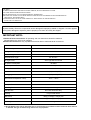
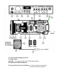
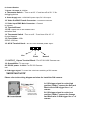
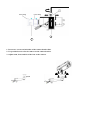
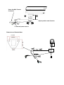
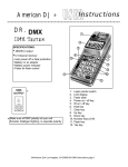
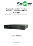
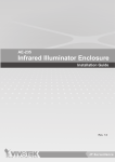
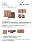
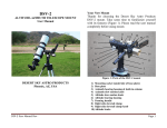
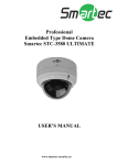
Smartec - STH-6230D-PSU2
INFRARED ILLUMINATOR ENCLOSURE
User Manual
www.smartec-security.eu
CAUTION:
TO REDUCE RISK OF FIRE OR ELECTRIC SHOCK, DO NOT REMOVE COVER.
NO USER SERVICEABLE PARTS INSIDE.
REFER SERVICING TO QUALIFIED SERVICE PERSONNEL.
THE INSTALLATION OF A SURGE PROTECTION DEVICE IS STRONGLY RECOMMENDED IN
FREQUENT THUNDER AREA.
LED RADIATION- DO NOT VIEW DIRECTLY WITH OPTICAL INSTRUMENTS
CLASS 1M LED PRODUCT
UNPACKING:
Unpack carefully. Electronic components can be damaged if improperly handled or dropped. If an item appears
having been damaged in shipment, place it properly in its carton and notify the shipper.
IMPORTANT NOTE:
1.Read and follow Instructions: All operating and user instructions should be read and
followed before the unit is to be operated.
2.Electrical Connections: Only a qualified electrician allow to make electrical connections.
Model Number
LED Quantity
STH-6230D-PSU2
11 IR LEDs
IR Light Distance Approach To
120M
IR wave length
850nm
Infrared Bean Angle
IR Light on/off
IR power consumption
Power Input
Rating Current of PSU2
25° and 45 °
Auto Light Sensor Control
16 Watts
AC90~240V (+/-10%)
5A
Heater Control
0°C (ON) / 10°C (OFF)
Defogging device
18°C (ON) / 28°C (OFF)
Environmental Operation Temp.
-40°C ~ +50°C
Protection Level
IP66
Temper Glass thickness
4mm
Mounting Bracket
Fully-cable Management
Construction
Die-Cast Aluminum Alloy
Coating
Ivory Powder Stove
Dimension
425(L) x 160(W) x 165(H) mm
Camera Space
200(L) x 110(W) x 115(H) mm
Net Weight
5230gm
● IR Light Distance are entirely dependant upon environmental site conditions and the location at which the unit
is situated. The type of camera being used is also very important.
1. Lens Cap with defogging device
2. Temper Glass
3. IR LED : 11pcs super high power IR LED with refractor .
4. IR Board and IR Board Bracket
5. Universal IR Control Circuit Board: To control color/mono switching
and IR on/off synchronization
.
6. Camera Bracket
7. Heater 1 & heater 2 : 230Vac
9. Thermostat Switch :. Turn on at 18
defogging device
C and turn off at 28
C for
8. Power Supply unit : .AC90-240V power input, DC 12V output.
10. Video Out BNC Female Connector : Connect to monitor
11. Video Input BNC Male Connector : Connect
to camera
12. Terminal Board
13. VR : Adjust VR to set Infrared LED
activation level .
14. Thermostat Switch : Turn on at 0
for dual heaters.
15. Fuse Holder : With
250V/3.15A fuse.
C and turn off at 10
C
16. AC IN Terminal block : AC 90~240V external power input .
L
Live
E
N
Earth
Neutral
17. OUTPUT_1 Spare Terminal Block : For AC 90~240V Camera use .
19. Ground Wire: To top cover.
20. DC12V power- in Jack: For DC12V Camera
use.
21. D/N trigger signal: To control the color/mono switching of D/N camera.
*IMPORTANT NOTE*
Please refer to the wiring diagram as below for install the D/N camera.
A: If IR trigger signal is on the high
position (+5Vdc), connect the Red and
Black wire to D/N trigger line +/- of
camera
Red wire:+5Vdc
Orange wire: 0Vdc
Black wire: Ground
B: If IR trigger signal is on the Low
position (+0Vdc), connect the Orange
and Black wire to D/N trigger line +/- of
camera.
Zoom Ring
1
3
1. Loosen two screws on both sides of the camera bracket first.
2. Use provided screw to fix the camera on the camera bracket.
3. Adjust zoom, focus and iris of the lens on the camera.
Video Out BNC Female
Connector
Adjust position and direction
To external power source
Dimensions of Bracket Base
110.00mm
83.00mm
95
.0
0
m
m
8.00mm