1
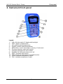
Earth / Clamp MI 3123 Instruction manual Version 1.0, Code no. 20 751 282 Distributor: Manufacturer: METREL d.d. Ljubljanska cesta 77 1354 Horjul Slovenia web site: http://www.metrel.si e-mail: [email protected] Mark on your equipment certifies that this equipment meets the requirements of the EU (European Union) concerning safety and electromagnetic compatibility regulations © 2008 METREL The trade names Metrel, Smartec, Eurotest, Autosequence are trademarks registered or pending in Europe and other countries. No part of this publication may be reproduced or utilized in any form or by any means without permission in writing from METREL. 2 MI 3123 Smartec Earth / Clamp Safety and operational considerations 1. Safety and operational considerations 1.1. Warnings This document is a supplement to the Instruction manual! Warning on the instrument means »Read the Instruction manual with special care to safety operation«. The symbol requires an action! If the test equipment is used in a manner not specified in this user manual the protection provided by the equipment might be impaired! Read this user manual carefully, otherwise use of the instrument may be dangerous for the operator, for the instrument or for the equipment under test! Do not use the instrument and accessories if any damage is noticed! Service intervention or adjustment and calibration procedure is allowed to be carried out only by a competent authorized person! Use only standard or optional test accessories supplied by your distributor! Instrument contains rechargeable NiCd or NiMh battery cells. The cells should only be replaced with the same type as defined on the battery placement label or in this manual. Do not use standard alkaline battery cells while power supply adapter is connected, otherwise they may explode! Disconnect all test leads, remove the power supply cable and switch off the instrument before removing battery compartment cover. All normal safety precautions have to be taken in order to avoid risk of electric shock when working on electrical installations! 3 MI 3123 Smartec Earth / Clamp Safety and operational considerations 1.2. Battery handling Before opening battery compartment cover disconnect all measuring accessories connected to the instrument and switch off the instrument. Insert cells correctly, otherwise the instrument will not operate and the batteries could be damaged. Remove all battery cells from the battery compartment if the instrument is not used for a long period of time. Alkaline or rechargeable Ni-Cd or Ni-MH batteries (size AA) can be used. The operating hours are given for cells with normal capacity of 2100 mAh. Do not charge alkaline battery cells! The battery is charged whenever the power supply adapter is connected to the instrument. In-built protection circuits control the charging procedure and assure maximal battery lifetime. Power supply socket polarity is shown in figure below. + Power supply socket polarity Note: Use only power supply adapter delivered from the manufacturer or distributor of the test equipment to avoid possible fire or electric shock! 1.3. Communication There are two communication interfaces available on the instrument: USB or RS 232. How to transfer stored data: RS 232 communication: connect a PC COM port to the instrument PS/2 connector using the PS/2 - RS232 serial communication cable; USB communication selected: connect a PC USB port to the instrument USB connector using the USB interface cable. Switch on the PC and the instrument. Run the Eurolink program. The PC and the instrument will automatically recognize each other. Note: USB drivers should be installed on PC before using the USB interface. Refer to USB installation instructions available on installation CD. Communication transfer speed: RS 232 ................ 115200 baud USB ..................... 256000 baud 4 MI 3123 Smartec Earth / Clamp Front panel 2. Instrument front panel Legend: 1 ..... 128 x 64 dots matrix LC display with backlight. 2 ..... TEST, starts a measurement. 3 ..... UP, modifies selected parameter. 4 ..... DOWN, modifies selected parameter. 5 ..... MEM, Store / recall / clear tests in memory of instrument. 6 ..... Function selectors, select test function. 7 ..... Changes backlight level and contrast. 8 ..... Switches the instrument power on or off. 9 ..... HELP, Accesses help menus. 10 ... TAB, selects the parameters in selected function. 11 ... PASS, indicates acceptance of result. 12 ... FAIL, indicates acceptance of result. 5 MI 3123 Smartec Earth / Clamp Resistance to earth 3. Measurements 3.1. Resistance to earth 1 3 Set function Select EARTH function using the function selector switch Use UP / DOWN keys to select test sub-function [Re, 1clamp, 2-clamps]. Resistance to earth measurement – lighting protection Resistance to earth measurement, one clamp – particular earthings Resistance to earth measurement, 2 clamps – for urban area 5 Set parameters and limits Limit ...... Maximum resistance [OFF, 1 Ω ÷ 5 kΩ, 20 Ω (two clamps)]. Circuits for measuring resistance to earth Resistance to earth measurement, 4-wire – PE grounding 4 2 Measurement procedure Connect test cable /one clamp / two clamps to the top of the instrument. Connect test leads /one clamp / two clamps to the item to be tested. Press the TEST key to perform the measurement. Store the result by pressing the MEM key (optional). View results Displayed results for earth resistance measurement: R .................................. Resistance to earth. Rc ............................... Resistance of S probe. Rp ............................... Resistance of H probe. 6 MI 3123 Smartec Earth / Clamp Specific earth resistance 3.2. Specific earth resistance 1 3 Set function Select EARTH function using the function selector switch Use the keys UP / DOWN to select test sub-function [ρ]. 2 Set parameters and limits a ............. The distance between probes. [0.1 m ÷ 30 m] or [1 ft ÷ 100 ft] Circuit for measuring specific earth resistance Specific earth Resistance measurement 4 5 Measurement procedure Connect test cable to the top of the instrument. Connect test leads to the item to be tested. Select the distance (a) between test probes Press the TEST key to perform the measurement. Store the result by pressing the MEM key (optional). View results Displayed results for earth resistance measurement: ρ ................................... Specific earth resistance. Rc ............................... Resistance of current carrying probes (E+H). Rp ............................... Resistance of potential measuring probes (S+ES). 7 MI 3123 Smartec Earth / Clamp Current 3.2. Clamp current 1 3 Set function Select CURRENT TRMS function using the function selector switch. 2 Set parameters and limits Limit ........ Selection of maximum leakage current [OFF, 0.1 mA÷ 100 mA]. Circuits for measurement leakage and load current Current measurement – connection of current clamp 4 5 Measurement procedure Connect current clamp to the top of the instrument. Embrace the tested conductor with current clamp Press the TEST key to start the measurement. Press the TEST key to stop the measurement. Store the result by pressing the MEM key (optional). View results Displayed result: I .................................... Load or leakage current. 8