1
Harman Kardon
Service Manual
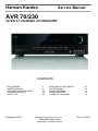
AVR 70/230
5x75W 5.1 CHANNEL A/V RECEIVER
CONTENTS
ESD WARNING
OWNER’S MANUAL
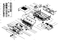
EXPLODED VIEW AND PARTS
TROUBLESHOOTING
PARTS LIST
Released EU2012
2
3
29
30
33
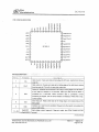
SEMICONDUCTOR PINOUTS
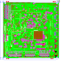
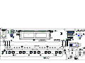
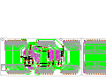
PCB DRAWINGS
BLOCK DIAGRAMS
WIRING DIAGRAM
SCHEMATIC DIAGRAMS
Harman Consumer Group, Inc.
8500 Balboa Boulevard
Northridge, California 91329
46
63
74
78
79
Rev 0, 06/2012
harman/kardon
Service manual AVR745EU
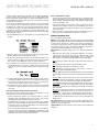
Some semiconductor (solid state) devices can be damaged easily by static electricity. Such components commonly are called
Electrostatically Sensitive (ES) Devices. Examples of typical ES devices are integrated circuits and some field effect transistors and
semiconductor "chip" components.
The following techniques should be used to help reduce the incidence of component damage caused by static electricity.
1. Immediately before handling any semiconductor component or semiconductor-equipped assembly, drain off any electrostatic charge on
your body by touching a known earth ground. Alternatively, obtain and wear a commercially available discharging wrist strap device,
which should be removed for potential shock reasons prior to applying power to the unit under test.
2. After removing an electrical assembly equipped with ES devices, place the assembly on a conductive surface such as aluminum foil, to
prevent electrostatic charge build-up or exposure of the assembly.
3. Use only a grounded-tip soldering iron to solder or unsolder ES devices.
4. Use only an anti-static solder removal device. Some solder removal devices not classified as "anti-static" can generate electrical charges
sufficient to damage ES devices.
5. Do not use freon-propelled chemicals. These can generate electrical change sufficient to damage ES devices.
6. Do not remove a replacement ES device from its protective package until immediately before you are ready to install it. (Most replacement
ES devices are packaged with leads electrically shorted together by conductive foam, aluminum foil or comparable conductive material.)
7. Immediately before removing the protective material from the leads of a replacement ES device, touch the protective material to the
chassis or circuit assembly into which the device will be installed.
CAUTION : Be sure no power is applied to the chassis or circuit, and observe all other safety precautions.
8. Minimize bodily motions when handling unpackaged replacement ES devices. (Otherwise harmless motion such as the brushing together
or your clothes fabric or the lifting of your foot from a carpeted floor can generate static electricity sufficient to damage an ES devices.
Each precaution in this manual should be followed during servicing.
Components identified with the IEC symbol
in the parts list are special significance to safety. When replacing a component identified with
, use only the replacement parts designated, or parts with the same ratings or resistance, wattage, or voltage that are designated in the
parts list in this manual. Leakage-current or resistance measurements must be made to determine that exposed parts are acceptably
insulated from the supply circuit before retuming the product to the customer.
Page 2 of 118
AVR 700/AVR 70/AVR 70C
Audio/video receiver
Owner’s Manual
FPO
AVR 700/AVR 70/AVR 70C
Introduction3
Table of Contents
Operating Your AVR
16
Supplied Accessories
3
Controlling the Volume
16
Important Safety Information
3
Muting the Sound
16
Place the AVR
3
Listening Through Headphones
16
Front-Panel Controls
4
Selecting a Source
16
Rear-Panel Connectors
5
Video Troubleshooting Tips
16
System Remote Control Functions
6
Listening to FM and AM Radio
16
Introduction to Home Theater
8
Listening to Media on a USB Device
16
Typical Home Theater System
8
Selecting a Surround Mode
17
Multichannel Audio
8
Surround Modes
8
Audio Processing and Surround Sound
17
Place Your Speakers
8
Adjusting the Channel Volumes
17
Placing the Left, Center and Right Speakers
8
Recording17
Placing the Surround Speakers
8
Sleep Timer
18
Placing the Subwoofer
8
Processor Reset
18
9
Memory18
Speaker Connections
9
Troubleshooting19
Subwoofer Connections
9
Specifications20
Source Device Connections
9
Appendix21
Types of Home Theater System Connections
Video Connections
10
Radio Connections
10
USB Port
10
Making Connections
11
Connect Your Speakers
11
Connect Your Subwoofer
11
Connect Your TV or Video Display
11
Connect Your Source Devices
11
Connect the Radio Antennas
13
Connect to AC Power
13
INSTALL BATTERIES IN the Remote Control
13
Set Up the AVR
14
2
Turn On the AVR
14
Using the On-Screen Menu System
14
Configure the AVR for Your Speakers
15
Additional Setup Menu Items
15
Advanced Functions
17
AVR 700/AVR 70/AVR 70C
Introduction, Supplied Accessories,
Important Safety Information and Place the AVR
Introduction
IMPORTANT SAFETY INFORMATION
Thank you for choosing this Harman Kardon product!
Verify Line Voltage Before Use
For more than fifty years, the Harman Kardon mission has been to share a passion for music
and entertainment, using leading-edge technology to achieve premium performance.
Sidney Harman and Bernard Kardon invented the receiver, a single component designed
to simplify home entertainment without compromising performance. Over the years,
Harman Kardon products have become easier to use while offering more features and
sounding better than ever.
The AVR 700 has been designed for use with 120-volt alternating current (AC). The
AVR 70 and AVR 70C have been designed for use with 220 – 240-volt AC. Connection
to a line voltage other than that for which your AVR is intended can create a safety
and fire hazard, and may damage the unit. If you have any questions about the voltage
requirements for your specific model or about the line voltage in your area, contact your
selling dealer before plugging the unit into a wall outlet.
The AVR 70, AVR 700 and AVR 70C 5.1-channel digital audio/video receivers (AVRs)
continue this tradition with some of the most advanced audio and video processing
capabilities yet and a wealth of listening and viewing options.
Do Not Use Extension Cords
To obtain the maximum enjoyment from your new AVR, please read this manual and refer
back to it as you become more familiar with its features and their operation.
If you have any questions about this product, its installation or its operation, please
contact your Harman Kardon retailer or custom installer, or visit our Web site at www.
harmankardon.com.
Supplied Accessories
The following accessory items are supplied with your AVR. If any of these items are
missing, please contact your Harman Kardon dealer, or Harman Kardon customer service
at www.harmankardon.com.
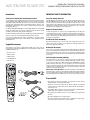
• IR remote control
• AM loop antenna
• FM wire antenna
• Three AAA batteries
• AC power cord
To avoid safety hazards, use only the power cord supplied with your unit. We do not
recommend that extension cords be used with this product. As with all electrical devices,
do not run power cords under rugs or carpets, or place heavy objects on them. Damaged
power cords should be replaced immediately by an authorized service center with a cord
meeting factory specifications.
Handle the AC Power Cord Gently
When disconnecting the power cord from an AC outlet, always pull the plug; never
pull the cord. If you do not intend to use your AVR for any considerable length of time,
disconnect the plug from the AC outlet.
Do Not Open the Cabinet
There are no user-serviceable components inside this product. Opening the cabinet may
present a shock hazard, and any modification to the product will void your warranty. If
water or any metal object such as a paper clip, wire or staple accidentally falls inside
the unit, disconnect it from the AC power source immediately, and consult an authorized
service center.
CATV or Antenna Grounding (AVR 700)
If an outside antenna or cable system is connected to this product, be certain that it is
grounded so as to provide some protection against voltage surges and static charges.
Section 810 of the United States National Electrical Code, ANSI/NFPA No. 70-1984,
provides information with respect to proper grounding of the mast and supporting
structure, grounding of the lead-in wire to an antenna discharge unit, size of grounding
conductors, location of antenna discharge unit, connection to grounding electrodes and
requirements of the grounding electrode.
NOTE TO CATV SYSTEM INSTALLER: This reminder is provided to call the CATV (cable
TV) system installer’s attention to article 820-40 of the NEC, which provides guidelines
for proper grounding and, in particular, specifies that the cable ground shall be connected
to the grounding system of the building, as close to the point of cable entry as possible.
Place the AVR
• Place the AVR on a firm and level surface. Be certain that the surface and any
mounting hardware can support the AVR’s weight.
• Provide proper space above and below the AVR for ventilation. Recommended
clearance distances are 30cm above the unit, 10cm behind the unit and 20cm on
each side of the unit.
• If you install the AVR in a cabinet or other enclosed area, provide cooling air within the
cabinet. Under some circumstances, a fan may be required.
• Do not obstruct the ventilation slots on the top of the AVR or place objects directly
over them.
• Do not place the AVR directly on a carpeted surface.
• Do not place the AVR in moist or humid locations, in extremely hot or cold locations,
in areas near heaters or heat registers, or in direct sunlight.
3
AVR 700/AVR 70/AVR 70C
Front-Panel Controls
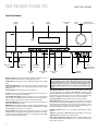
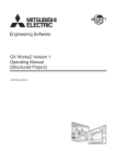
Front-Panel Controls
Standby
Indicator
Main Power
Switch
Message
Display
IR
Sensor
On/Standby
Switch
Surround Mode
Select Buttons
Stereo Mode
Button
Memory/Folder
Button
AM/FM
Button
Tuning Up/Down
Button
Main Power switch: This mechanical switch turns the AVR’s power supply on or off. It is
usually left on and cannot be turned on or off using the remote control.
Standby indicator: This LED glows amber to indicate that the AVR is in the Standby
mode.
Power On/Standby button: Press this button to turn the AVR on and put it into the
Standby mode. When the AVR is on the Power On indicator glows blue and the Standby
indicator turns off.
Stereo Mode button: Places the AVR in the stereo listening mode.
IR Sensor: This sensor receives infrared (IR) commands from the remote control. It is
important to ensure that the sensor is not blocked.
Surround Mode Select buttons: Press these buttons to select a surround listening
mode. Surround-mode availability depends on the nature of the source input signal, i.e.,
digital versus analog, and the number of channels encoded within the signal.
Tuning Up/Down buttons: Use these buttons to tune radio stations according to the
setting of the AM/FM button (see below).
AM/FM button: Press this button to listen to the radio. Pressing this button when the
radio is in use will select among the FM Stereo, FM Mono and AM bands. See Listening
to FM and AM Radio, on page 16, for more information.
Message display: Various messages appear in this display in response to commands
and changes in the incoming signal. In normal operation, the current source device name,
surround mode and active input appear. When the on-screen display menu system (OSD)
is in use, the current menu settings appear.
Source Select
Buttons
Preset Selector
Buttons
Volume
Control
USB
Port
Power On Indicator
(inside Volume Control ring)
Video 3
Audio and Video
Input Connectors
Headphone
Connector
IMPORTANT NOTE: If the PROTECT message ever appears on the Message Display,
turn off the AVR and unplug it from the AC outlet. Check all speaker wires for a
possible short circuit (the “+” and “–” conductors touching each other or both
touching the same piece of metal). If a short circuit is not found, bring the unit to
an authorized Harman Kardon service center for inspection and repair before using
it again.
Preset Selector buttons: When the radio is in use, press these buttons to cycle through
your preset radio stations.(See Listening to FM and AM Radio, on page 16, for more
information.) NOTE: When you're listening to files on a USB device, the Tuning Up/Down
buttons and the Preset Selector buttons serve as the USB device’s transport control
buttons.(See Playing Files on a USB Device, on page 16, for more information.)
Source Select buttons: Press these buttons to select the active source device.
Memory/Folder button: When the radio is in use, press this button to set the current
station as a preset. See Listening to FM and AM Radio, on page 16, for more information.
When a USB device is the active source deivce, press this button to display the contents
of the current folder or to display all of the folders in the current directory level. See
Playing files on a USB Device, on page 16, for more information.
Headphone connector: Connect a 1/4" stereo headphone plug to this jack for private
listening
USB Port: Insert a flash drive or HDD disk drive with a USB Standard-A cable to this port.
Volume control: Turn this knob to raise or lower the volume.
Video 3 Audio and Video Input connectors: Connect an auxiliary audio/video source
component that will be used only temporarily, such as a camcorder, portable music
player or game console, here.
4
AVR 700/AVR 70/AVR 70C
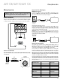
Rear-Panel Connectors
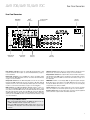
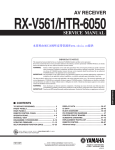
Rear-Panel Connectors
Digital Audio
Connectors
Radio Antenna
Connectors
Analog Audio
Connectors
HDMI®
Connectors
Composite Video
Connectors
Subwoofer
Connector
Radio Antenna connectors: Connect the included AM and FM antennas to their
respective terminals for radio reception. See Connect the Radio Antennas, on page 13,
for more information.
AC Input
Connector
Speaker
Connectors
Subwoofer connector: Connect this jack to a powered subwoofer that has a line-level
input connector. See Connect Your Subwoofer, on page 11, for more information.
Digital Audio connectors: If your non-HDMI source devices have digital outputs,
connect them to the AVR’s digital audio connectors. See Connect Your Source Devices,
on page 11, for more information.
Composite Video connectors: Use composite video connectors for video source devices
and a TV that don’t have HDMI connectors. You will also need to make audio connections
from the source devices to the AVR. See Connect Your Source Devices, on page 11, for
more information.
Analog Audio connectors: Use the AVR’s Analog Audio connectors for source devices
that don’t have HDMI or digital audio connectors. Use the Video 1 Out, Video 2 Out and
Tape Out connectors to connect to the audio inputs of VCRs, tape decks or other analog
recorders. See Connect Your Source Devices, on page 11, for more information.
IMPORTANT: The AVR’s on-screen display (OSD) only appears through the Composite
Monitor Out connector. If you want to use the AVR’s OSD menus you need to connect
its Composite Monitor Out connector to your TV even if you are not connecting any
composite video source devices to the AVR.
HDMI connectors: The HDMI (High-Definition Multimedia Interface®) feature is a
connection for transmitting digital audio and video signals between devices. If your
source devices and TV have HDMI connectors, using them will provide the best possible
video and audio performance quality. Since the HDMI cable carries both digital video
and digital audio signals, you do not have to make any additional audio connections for
devices you connect via HDMI connections. See Connect Your Source Devices, on page
11, for more information.
Speaker connectors: Use two-conductor speaker wire to connect each set of terminals
to the correct speaker. See Connect Your Speakers, on page 11, for more information.
AC Input connector: After you have made all other connections, plug the supplied AC
power cord into this receptacle and into an unswitched wall outlet.
Notes on using the HDMI Out connector:
• When connecting a DVI-equipped display to the HDMI Monitor Out connector, use
an HDMI-to-DVI adapter and make a separate audio connection.
• Make sure the HDMI-equipped display is HDCP-compliant. If it isn’t, do not connect
it via HDMI; use an analog video connection instead and make a separate audio
connection.
5
AVR 700/AVR 70/AVR 70C
System Remote Control Functions
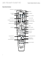
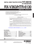
Remote Control Functions
IR Transmitter Lens
Mute Button
Power On Button
Power Off Button
AVR Button
Source Selector Buttons
Stereo Mode Button
Surround Mode Select Buttons
Display Mode Button
Audio Input Select Button
Tone Controls Button
Volume Up/Down Buttons
Test Tone Sequence Button
Setup Menu Button
OK Button
Back/Exit Button
Channel Level Button
Left/Right/Up/Down Buttons
Number Buttons
Memory Button
Tuning Up/Down Buttons
Sleep/Clear Button
Track Skip Up/Down Buttons
Preset Station Up/Down Buttons
Display Dim Button
Repeat/Random Button
Transport Control Buttons
6
AVR 700/AVR 70/AVR 70C
Remote Control Functions, continued
In addition to controlling the AVR, the AVR remote can also control a Harman Kardon Bluray Disc® or DVD player that is connected to the HDMI 1 connector. The remote control
buttons will have different functions depending on if the remote is controlling the AVR or
a Blu-ray Disc or DVD player. Appendix A5, Remote Control Function List, on page 25,
provides a list of the different remote control button functions when controlling a Blu-ray
Disc or DVD player.
IR Transmitter lens: As buttons are pressed on the remote, infrared codes are emitted
through this lens.
Power On/Off buttons: Press these buttons to turn the AVR on and off. The Main Power
switch on the AVR’s front panel must be on for these buttons to turn the AVR on and off.
Mute button: Press this button to mute the AVR’s speaker-output connectors and
Headphone jack. To restore the sound, press this button or adjust the volume.
AVR button: Press this button to switch the remote’s control mode to operate the AVR.
Pressing this button when the AVR is in the Standby mode will turn it on.
Source Selector buttons: Press one of these buttons to select a source device. This
action will also turn on the AVR and switch the AVR to the selected input.
• Pressing the TV Source Selector button plays the sound from the HDMI Audio Return
Channel, so you can listen to sources connected directly to the TV or to the TV itself
through the AVR. See Additional Setup Menu Items: HDMI Set, on page 15, for more
information.
• The first press of the Radio Source Selector button switches the AVR to the last-used
tuner band (AM or FM). Successive presses cycle through AM, FM stereo and FM
mono.
Stereo Mode button: Press this button to switch to the stereo listening mode.
Tone Controls button: Press this button to activate or bypass the bass and treble
controls. When the tone controls are set to “ON”, use the up, down, left and right arrow
buttons to vary the tone quality by adjusting the bass and treble.
Surround Mode Select buttons: Press these buttons to select a surround listening
mode. Surround-mode availability depends on the nature of the source input signal,
i.e., digital versus analog, and the number of channels encoded within the signal. See
Selecting a Surround Mode and Audio Processing and Surround Sound, on page 17, for
more information.
Volume Up/Down buttons: Press these buttons to raise or lower the volume.
Display Mode button: Press this button to display the active surround mode and current
volume control setting on the AVR’s Message Display. After five seconds the display will
revert back to showing the currently-active source.
Test Tone sequence button: Press this button to activate the test tone for calibrating
channel volume levels by ear.
System Remote Control Functions, continued
Audio Input Select button: Press this button to select the specific digital audio input (or
analog audio input) to which the current source is connected. Each press of the button
advances through the following inputs: Optical Digital 1, Optical Digital 2, Coaxial Digital,
HDMI (for HDMI 1 – HDMI 3 only) and Analog. This button does not function for the AM/
FM and USB sources.
Setup Menu button: Press this button to activate the setup menus. See Set Up the AVR,
on page 14, for more information.
OK button: This button is used to select items from the menu system.
Back button: When you’re using the setup menus, press this button to return to the
previous menu screen.
Channel Level button: Press this button to activate the individual channel-level
adjustment. It lets you easily change the channel balance while you’re listening to suit
different programs or seating arrangements. See Set Up the AVR, on page 14, for more
information.
Left/Right/Up/Down buttons: These buttons are used to navigate the menu system.
Number buttons: Use these buttons to enter numbers for radio-station frequencies or
to select station presets.
Memory button: To save the currently tuned radio station as a preset, press this button,
then a Number button.
Tuning Up/Down buttons: Press these buttons to tune a radio station. When you’re
listening to an FM station, each press will either change one tuning frequency increment
at a time or seek the next higher or lower station with acceptable signal strength,
depending on whether you are listening in FM mono or FM stereo.
Preset Station Up/Down buttons: Press these buttons to cycle through your preset
radio stations.
Sleep/Clear button: Press this button to activate the Sleep Timer function. See Sleep
Timer, on page 18, for more information. When controlling a Harman/Kardon Blu-ray Disc
or DVD player, press this button to clear an entry.
Display Dimmer button: Press this button to dim the AVR’s front-panel display partially
or fully.
Repeat/Random button: This button has no effect on the AVR but can be used to
activate the repeat function when you’re listening to media on a device inserted into the
AVR’s USB port and the repeat and random functions on a Harman Kardon Blu-ray Disc or
DVD player. See Listening to Media on a USB Device, on page 16, for more information.
Track Skip Up/Down buttons: These buttons have no effect on the AVR but are used to
change tracks or chapters when you’re listening to media on a device inserted into the
AVR’s USB port, or on a Harman Kardon Blu-ray Disc or DVD player.
Transport Control buttons: These buttons have no effect on the AVR but are used to
control a Harman Kardon Blu-ray Disc player or DVD player or a device inserted in the
AVR’s USB port.
7
Introduction to Home Theater
and Place Your Speakers
AVR 700/AVR 70/AVR 70C
Introduction to Home Theater
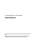
Place Your Speakers
This introductory section will help you to familiarize yourself with some basic concepts
unique to multichannel surround-sound AVRs, which will make it easier for you to set up
and operate your AVR.
Determine the locations for your system’s speakers according to their manufacturer’s
directions and the layout of your listening room. Use the illustration below as a guide for
5.1-channel systems.
Typical Home Theater System
To create the most realistic surround-sound environment possible, you should place
your speakers in a circle with the listening position at its center. You should angle each
speaker so it directly faces the listening position. Use the diagram below as a guide.
A home theater typically includes an audio/video receiver (AVR), which controls the system
and supplies amplification for the loudspeakers; a disc player; a source component for
television broadcasts (cable box, satellite dish AVR, HDTV tuner or antenna connected to
the TV); a TV or video display; and multiple loudspeakers.
TV
C
FL
Multichannel Audio
SUB
FR
The main benefit of a home theater system is its ability to produce “surround sound.”
Surround sound uses multiple speakers and amplifier channels to immerse you in the
audio/video presentation for a dramatically increased sense of realism.
Your AVR can have up to five main speakers connected directly to it, plus a subwoofer.
Each main speaker is powered by its own amplifier channel inside the AVR. A system
with more than two speakers is called a multichannel system. The different main speaker
types in a home theater system are:
SL
SR
• Front Left and Right: The front left and right speakers are used as in a 2-channel
system. In many surround-sound modes, these speakers are secondary, while the
main action, especially dialogue, is reproduced by the center speaker.
• Center: When you are watching movies and television programs, the center speaker
reproduces most of the dialogue and other soundtrack information that occurs on the
screen, anchoring it with the picture. When you are listening to a musical program,
the center speaker helps to create a seamless front soundstage, creating a more
realistic “you-are-there” listening experience.
• Surround Left and Right: The surround left and right speakers produce ambient
sounds that help create a realistic and immersive surround-sound environment. They
also help recreate directional sound effects such as aircraft flyovers.
Many people expect the surround speakers to play as loudly as the front speakers.
Although you will calibrate all of the speakers in your system to sound equally loud
at the listening position, most artists use the surround speakers for ambient effects
only, and they create their programs to steer relatively little sound to these speakers.
• Subwoofer: A subwoofer is designed to play only the lowest frequencies (the deep
bass). It augments smaller, limited-range main speakers that are usually used for
the other channels. Many digital-format programs, such as movies recorded in Dolby
Digital, contain a low-frequency effects (LFE) channel that is directed to the subwoofer.
The LFE channel packs the punch of a rumbling train or airplane, or the power of an
explosion, adding realism and excitement to your home theater. Some people use two
subwoofers for additional power and for even distribution of the sound.
There are different theories as to the best way to present surround sound and to distribute
the individual channel information to the surround-sound system’s speakers. A variety
of algorithms have been developed in an effort to recreate the way we hear sounds in
the real world, resulting in a rich variety of options. Several companies have developed
different surround-sound technologies, all of which can be accurately reproduced by
your AVR:
• Dolby Laboratories: Dolby TrueHD, Dolby Digital Plus, Dolby Digital, Dolby Pro Logic II,
Dolby Pro Logic.
• DTS: DTS-HD High Resolution Audio, DTS-HD Master Audio , DTS, DTS 96/24 ,
DTS Neo: 6.
™
™
• HARMAN International: Analog Surround Modes (Theater Hall, Stadium, Club,
Arena).
• Stereo Modes: 2-channel stereo and 5-channel stereo.
Appendix Table A4, on page 22, contains detailed explanations of the different surroundsound options available on your AVR. Digital surround-sound modes, such as Dolby
Digital and DTS systems, are available only with specially encoded programs, such
as those available via HDTV, DVD and Blu-ray Disc media and digital cable or satellite
television. Other surround modes may be used with digital and analog signals to create a
different surround presentation or to use a different number of speakers. Surround-mode
selection depends upon the number of speakers in your system, the programs you are
watching or listening to, and your personal tastes.
8
Place the center speaker either on top of, below or mounted on the wall above or below
the TV or video-display screen. Place the front left and right speakers along the circle,
about 30 degrees from the center speaker and angled toward the listener.
Place the front left, front right and center speakers at the same height, preferably at
about the same height as the listener’s ears. The center speaker should be no more than
2 feet (0.6m) above or below the left/right speakers. If you’re using only two speakers
with your AVR, place them in the front left and front right positions.
Placing the Surround Speakers
You should place the left and right surround speakers approximately 110 degrees from
the center speaker, slightly behind and angled toward the listener. Alternatively, you can
place them behind the listener, with each surround speaker facing the opposite-side
front speaker. You should place the surround speakers 2 feet – 6 feet (0.6m – 1.8m)
higher than the listener’s ears.
NOTE: Your AVR will sound its best when the same model or brand of
loudspeaker is used for all positions.
Surround Modes
™
Placing the Left, Center and Right Speakers
Placing the Subwoofer
Because a room’s shape and volume can have a dramatic effect on a subwoofer’s
performance, it is best to experiment with placement so that you will find the location
that produces the best results in your particular listening room. With that in mind, these
rules will help you get started:
• Placing the subwoofer next to a wall generally will increase the amount of bass in
the room.
• Placing the subwoofer in a corner generally will maximize the amount of bass in the
room.
• In many rooms, placing the subwoofer along the same plane as the left and right
speakers can produce the best integration between the sound of the subwoofer and
that of the left and right speakers.
• In some rooms, the best performance could even result from placing the subwoofer
behind the listening position.
A good way to determine the best location for the subwoofer is by temporarily placing it in
the listening position and playing music with strong bass content. Move around to various
locations in the room while the system is playing (putting your ears where the subwoofer
would be placed), and listen until you find the location where the bass performance is
best. Place the subwoofer in that location.
Types of Home Theater
System Connections
AVR 700/AVR 70/AVR 70C
Types of Home Theater System Connections
Subwoofer Connections
There are different types of audio and video connections used to connect the AVR to your
speakers, your TV or video display, and your source devices. The Consumer Electronics
Association has established the CEA® color-coding standard.
The subwoofer is a speaker dedicated to reproducing only the low (bass) frequencies,
which require more power. To obtain the best results, most speaker manufacturers offer
powered subwoofers that contain their own amplifiers. Use a single RCA audio cable
(not included) to make a line-level (non-amplified) connection from the AVR’s Subwoofer
connector to a corresponding input jack on the subwoofer.
Connection Color Guide Table
Analog Audio Connection
Color
Front Left/Right
White/Red
Center
Green
Surround Left/Right
Blue/Gray
Subwoofer
Purple
Digital Audio Connection
Color
Coaxial (input or output)
Orange
Optical Input
Black
Analog Video Connection
Color
Composite Video
Yellow
Speaker Connections
Speaker cables carry an amplified signal from the AVR’s speaker terminals to each
loudspeaker. Each cable contains two wire conductors, or leads, that are differentiated
in some way, such as with colors or stripes.
The differentiation helps you maintain proper polarity, without which your system’s lowfrequency performance can suffer. Each speaker is connected to the AVR’s speakeroutput terminals using two wires, one positive (+) and one negative (–). Always connect
the positive terminal on the speaker, which is usually colored red, to the positive terminal
on the AVR, which is colored as indicated in the Connection Color Guide Table, above.
The negative terminals on the speakers and the AVR are black.
Your AVR uses binding-post speaker terminals that can accept bare-wire cables or
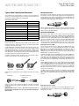
banana plugs. Bare-wire cables are installed as shown below:
1. Unscrew Cap
2. Insert Bare Wire
3. Tighten Cap
Banana plugs are inserted into the hole in the middle of the terminal cap, as shown
below:
A. Tighten Cap
Although the AVR’s purple subwoofer output looks similar to a full-range analog audio
jack, it is filtered so that only the low frequencies pass through it. Don’t connect this
output to any device other than a subwoofer.
Source Device Connections
Audio and video signals originate in source devices (components where a playback
signal originates) such as your Blu-ray Disc or DVD player, CD player, DVR (digital video
recorder) or other recorder, tape deck, game console, cable or satellite television tuner,
MP3 player or a device docked in the AVR’s USB port. The AVR’s FM/AM tuner also counts
as a source, even though no external connectors are needed other than the AVR’s FM and
AM antennas. Separate connectors are required for the audio and video portions of the
source device’s signal, except for digital HDMI connectors. The types of connectors you
use will depend upon the capabilities of the source device and of your TV or video display.
Digital Audio Connections – HDMI
There are two types of audio connections – digital and analog. Digital audio signals are
required for listening to sources encoded with digital surround modes, such as Dolby
Digital and DTS, or for uncompressed PCM digital audio. Your AVR has three types of
digital audio connectors: HDMI, coaxial and optical. Do not use more than one type of
digital audio connector for each source device. However, it’s okay to make both analog
and digital audio connections to the same source.
Your AVR is equipped with four rear-panel HDMI input connectors and one HDMI monitor
output connector. HDMI technology enables digital audio and video information to be
carried using a single cable, delivering the highest quality picture and sound. If your TV
or video-display device has an HDMI input connector, make a single HDMI connection
from each source device to the AVR. Usually, a separate digital audio connection is not
required.
The AVR’s HDMI Monitor Output connector contains an Audio Return Channel (ARC) that
carries a digital audio signal from your TV or video display back to the AVR. It allows
you to listen to HDMI devices that are connected directly to your TV (such as an Internet
connection) without making an additional connection from the device to the AVR. The
ARC signal is active when the TV source is selected. See Additional Setup Menu Items,
on page 15, for more information.
The HDMI connector is shaped for easy plug-in (see illustration, below), and HDMI
cable runs are limited to about 10 feet (3m). If your video display has a DVI input and is
HDCP-compliant, use an HDMI-to-DVI adapter (not included), and make a separate audio
connection.
B. Insert Banana Connector
into Hole in Cap
Always connect the colored (+) terminal on the AVR to the (+) terminal on the speaker
(usually red), and the black (–) terminal on the AVR to the (–) terminal on the speaker
(usually black).
IMPORTANT: Make sure the ( + ) and ( – ) bare wires do not touch each other or
the other terminal. Touching wires can cause a short circuit that can damage your
AVR or amplifier.
Digital Audio Connections – Coaxial
Coaxial digital audio jacks are usually color-coded orange. Although they look like
standard RCA-type analog jacks, you should not connect coaxial digital audio outputs to
analog inputs or vice versa.
9
Types of Home Theater System
Connections, continued
AVR 700/AVR 70/AVR 70C
Digital Audio Connections – Optical
Radio Connections
Optical digital audio connectors are normally covered by a shutter to protect them from
dust. The shutter opens as the cable is inserted. Optical input connectors are color-coded
using a black shutter.
Your AVR uses separate terminals for the included FM and AM antennas. The FM antenna
uses a 75-ohm F-connector.
Analog Audio Connections
The AM antenna connector uses spring-clip terminals. After assembling the antenna
as shown below, press the levers to open the connectors, insert the bare wires into the
openings, and release the levers to secure the wires.
Two-channel analog connections require a stereo audio cable, with one connector for
the left channel (white) and one for the right channel (red). These two connectors are
attached to each other.
USB Port
For source devices that have both digital and analog audio outputs, you may make both
connections.
The analog connections also feed the Analog Record Output connectors. You may record
materials from Blu-ray Disc recordings, DVDs or other copy-protected sources using only
analog connections. Remember to comply with all copyright laws if you choose to make
a copy for your own personal use.
The AVR can play MP3 and WMA audio files from a USB device inserted into the USB port.
Insert the device into the USB port oriented so it fits all the way into the port. You may
insert or remove the device at any time – there is no installation or ejection procedure.
Video Connections
Many source devices output both audio and video signals (e.g., Blu-ray Disc, DVD
player, cable television box, HDTV tuner, satellite box, VCR, DVR). In addition to an audio
connection as described above, make a video connection for each of these source
devices. Make only one type of video connection for each device.
Digital Video Connections
If you have already connected a source device to one of the AVR’s HDMI input connectors,
you have automatically made a video connection for that device, since the HDMI cable
carries both digital audio and digital video signals.
Analog Video Connections – Composite Video
Composite video is the basic connection most commonly available. Both the chrominance
(color) and the luminance (intensity) components of the video signal are transmitted
using a single cable. The jack is usually color-coded yellow and looks like an analog
audio jack. Do not connect a composite video jack to an analog audio or coaxial digital
audio jack, or vice versa.
10
IMPORTANT: Do not connect a PC or other USB host/controller to the AVR’s USB
port, or you may damage both the AVR and the other device.
AVR 700/AVR 70/AVR 70C
Making Connections
Making Connections
Connect Your TV or Video Display
HDMI Monitor Out connector
CAUTION: Before making any connections to the AVR, ensure that the AVR’s AC
power cord is unplugged from the AVR and the AC outlet. Making connections
with the AVR plugged in and turned on could damage the speakers.
If your TV has an HDMI connector and you have HDMI or component video source
devices, use an HDMI cable (not included) to connect your TV to the AVR’s HDMI Monitor
Out connector. It will provide the best possible picture quality.
TV
Connect Your Speakers
After you have placed your loudspeakers in the room as explained in Place Your Speakers,
on page 8, connect each speaker to its color-coded terminal on the AVR as explained
in Speaker Connections, on page 9. Connect the speakers as shown in the illustration.
AVR HDMI
Monitor Out
Connector
HDMI Cable
(not supplied)
Composite Video Monitor Out connector
If your TV does not have an HDMI connector, or if your TV does have an HDMI connector
but you are connecting some source devices with only composite video connectors, use
a composite video cable (not included) to connect the AVR’s Composite Monitor Out
connector to your TV’s composite video connector.
IMPORTANT: The AVR’s on-screen display (OSD) only appears through the Composite
Monitor Out connector. If you want to use the AVR’s OSD menus you need to connect
its Composite Monitor Out connector to your TV even if you are not connecting any
composite video source devices to the AVR.
FL
C
AVR Composite
Monitor Out
Connector
FR
TV
Composite Video Cable
(not supplied)
Connect Your Source Devices
SL
SR
Connect Your Subwoofer
Use a single RCA audio cable to connect the AVR’s Subwoofer Out connector to your
subwoofer. Consult your subwoofer’s user manual for specific information about making
connections to it.
Single
RCA Audio Cable
(not supplied)
AVR
Subwoofer
Connector
Powered
Subwoofer
Source devices are components where a playback signal originates, such as a
Blu-ray Disc or DVD player, or a cable, satellite or HDTV tuner. Your AVR has several
different types of input connectors for your audio and video source devices: HDMI,
composite video, optical digital audio, coaxial digital audio and analog audio.
Each of your AVR’s source buttons is assigned to an HDMI connector or an analog audio
input connector (listed in the “AVR Source Button/Analog Audio Connector” column of
the table below).The digital inputs are not assigned to any specific sets of analog inputs.
Once you select a source device you can use the remote control’s Audio Input Select
(DIGITAL) button to select the specific audio input connection (HDMI, coaxial digital,
optical digital, analog) that you want to listen to. (Note: You cannot select an audio input
connection for the FM/AM or USB source buttons.)
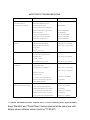
As you connect your various source components, fill out the “Source Device Connected”
and “Digital Audio Input Connector Used” columns in the following table – it will make it
easy to keep track of which devices you have connected to which connectors. Note: The
AVR remote is pre-programmed to control a Harman/Kardon Blu-ray Disc or DVD player
connected to HDMI 1.
AVR Source Button/
Analog Audio Connector
Source Device Connected
Digital Audio Input
Connector Used
Source Device Connected
Digital Audio Input
Connector Used
Video 1
Video 2
Video 2
Tape
Aux
AVR Source Button/
HDMI Connector
*HDMI 1
HDMI 2
HDMI 3
*The AVR remote is pre-programmed to control a Harman/Kardon Blu-ray Disc or DVD player
connected to HDMI 1.
11
AVR 700/AVR 70/AVR 70C
Making Connections, continued
HDMI devices
Optical digital audio devices
If any of your source devices have HDMI connectors, using those connectors will provide
the best possible video and audio performance quality. Since the HDMI cable carries
both digital video and digital audio signals, you do not have to make any additional audio
connections for devices you connect via HDMI cables.
If your source devices have optical digital outputs, connect them to the AVR’s Optical
Digital Audio connectors. NOTE: Make only one type of digital connection (HDMI, optical
or coaxial) from each device.
• The AVR remote control is pre-programmed to control a Harman/Kardon Blu-ray Disc
or DVD player when the HDMI 1 Source Selector button is pressed.
AVR Digital Audio
Connectors
If you have a TV equipped with the HDMI Audio Return Channel function, its sound is fed
to the AVR via the HDMI Out connector’s Audio Return Channel, and it will not require
additional audio connections to the AVR.
AVR HDMI
Connectors
Optical Digital Audio
Cable (not supplied)
To Optical Digital
Audio Output
Optical-Equipped
Source Device
HDMI Cable
(not supplied)
To HDMI
Output
HDMI-Equipped Source Device
Composite video devices
Coaxial digital audio devices
If your source devices have coaxial digital outputs, connect them to the AVR’s Coaxial
Digital Audio connectors. NOTE: Make only one type of digital connection (HDMI, optical
or coaxial) from each device.
AVR Digital Audio
Connectors
You will need to make composite video connections from your source devices that do
not have HDMI connectors. You will also need to make an audio connection from the
device to the AVR.
AVR Component
Video Connectors
Coaxial Digital Audio
Cable (not supplied)
To Coaxial Digitial
Audio Output
Composite Video
Cable (not supplied)
Coaxial Digital-Equipped
Source Device
To Composite
Video Output
Analog audio devices
Composite Video-Equipped
Source Device
Make analog audio connections from your source devices that do not have HDMI or
digital audio connectors. If you’re connecting video sources to the Video 1, Video 2 or
Video 3 audio inputs, you must also connect the source device’s composite video output
to the corresponding composite video connector.
AVR Analog Audio
Connectors
Stereo Audio Cable
(not supplied)
To Stereo Analog
Audio Output
Analog Source Device
12
AVR 700/AVR 70/AVR 70C
Making Connections, continued
Audio recorders
Connect to AC Power
Connect an analog audio recorder’s inputs to the AVR’s analog audio Tape Out connectors.
You can record any analog audio input signal except for the Tape 1 input.
Connect the AC power cord to the AVR’s AC Input connector and then to a working AC
power outlet.
AVR Analog Audio
Recorder Connectors
AVR AC
Input Connector
AC Power
Outlet
Power Cord
(supplied)
Stereo Audio Cable
(not supplied)
To Stereo Analog
Record Inputs
Analog Recording Device
Install the Batteries in the Remote Control
Remove the remote control’s battery cover, insert the three supplied AAA batteries as
shown in the illustration, and replace the battery cover.
Video recorders
Connect an analog video recorder’s video input connector to the AVR’s Video 1 Out
Composite Video connector, and its audio input connectors to the AVR’s Video 1 Out
Analog Audio connectors. You can record the Video 2 or Video 3 composite video input
signals.
AVR Analog
Audio Connectors
AVR Composite
Video Connectors
To Analog Audio/
Video Record Inputs
Analog Audio/Video
Cable (not supplied)
NOTE: Remove the protective plastic from the AVR’s front panel to keep it from reducing
the remote control’s effectiveness.
Analog Video
Recording Device
Connect the Radio Antennas
• Connect the supplied FM antenna to the AVR’s FM 75Ω Radio Antenna connector. For
the best reception, extend the FM antenna as far as possible.
• Bend and fold the base of the supplied AM antenna as shown and connect the
antenna wires to the AVR’s AM and Gnd connectors. Rotate the antenna as necessary
to minimize background noise.
AVR Antenna
Connectors
FM Antenna (supplied)
AM Antenna
(supplied)
Bend and fold base
13
AVR 700/AVR 70/AVR 70C
Set Up the AVR
Set Up the AVR
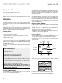
Configure the AVR for Your Speakers
Turn On the AVR
1. Turn on your TV and select the TV’s composite video input where you connected the
AVR in Connect Your TV or Video Display, on page 11.
1. Set the front-panel Main Power switch to “On.” (The front-panel Standby indicator
will glow amber.)
2. Press the remote control’s SETUP button. The AVR’s on-screen display (OSD) System
Setup menu will appear on the TV.
2. Press the front-panel On/Standby switch.
Standby
Indicator
Stereo
Surr.Select
Tuning
AM/FM
Preset
Source
Memory
Folder
Power
Phones
5V
Main Power
Switch
USB
500A
Video
L Audio R
Video 3
3. Use the remote’s arrow and OK buttons to select “Speaker Setup.” The Speaker Setup
menu will appear.
On/Standby
Button
Unless you will not be using the AVR for an extended period of time, leave the Main Power
switch set to “On.” When the Main Power switch is turned off, any settings you have
programmed will be preserved for up to two weeks.
IMPORTANT NOTE: If the PROTECT message ever appears in the Message
display, turn off the AVR and unplug it. Check all speaker wires for a short
circuit (“+” and “–” wires touching). If none is found, bring the unit to an
authorized Harman Kardon service center for inspection and repair before
using it again.
4. Select “Speaker Settings.” The Speaker Settings menu will appear.
Using the On-Screen Menu System
Although it’s possible to configure the AVR using only the remote and the front-panel
Message display, it is easier to use the on-screen menu system.
To access the menu system, turn on your TV and select the TV’s composite video input
where you connected the AVR in Connect Your TV or Video Display, on page 11.
Press the remote control’s SETUP button. The AVR’s on-screen display (OSD) System
Setup menu will appear on the TV.
5. Use the remote’s left and right arrow buttons to select OFF, SMALL or LARGE for the
Front, Center and Surround speaker positions, depending on the speakers you have
connected to the receiver.
OFF: Select this setting if you have not connected a speaker in that position (not available
for the Front speakers).
SMALL: Select this setting if the speaker is not capable of producing clean, deep bass
energy at output levels that match those produced by a powered subwoofer. All bass
below the crossover frequency (see Step 6, below) in that channel is removed from that
speaker and is sent to the subwoofer (or to the Front speakers if Subwoofer is set to NO).
Most speakers (unless they are large and powerful) should be considered SMALL.
The System Setup menu consists of five submenus: Speaker Set, HDMI Set, Parameter,
Auto Power Control and Speaker On/Off.
Use the Up/Down/Left/Right buttons on the remote to navigate the menu system, and
press the OK button to select a menu or setting line, or to enter a new setting.
The current menu, setting line or setting will appear in the front-panel Message display,
as well as on screen.
LARGE: Select this setting if the speaker is capable of producing clean, deep bass energy
at output levels that match those produced by a powered subwoofer. All bass in that
channel is sent to that speaker.
NOTE: If your system has a subwoofer and you set the Front speakers to LARGE, the
subwoofer may not output audio except for Dolby Digital- and DTS-encoded program
material that contains LFE channel information. If you set your Front speakers to LARGE
and you want your subwoofer to reproduce bass from all program material, set the
Subwoofer to PLUS (see below).
To return to the previous menu, press the remote’s BACK button. To exit the menu
system, press the SETUP button.
For Subwoofer, select YES (if your system has a subwoofer), NO (if your system does not
have a subwoofer), or PLUS (if your system has a subwoofer, you set your Front speakers
to LARGE and you want your subwoofer to reproduce bass from all program material).
Follow the instructions in this Set Up the AVR section to configure your home theater
system. You may return to these menus at any time to make additional adjustments.
When you’re finished, record your settings in Table A2 of the Appendix, on page 21, then
press the remote control’s BACK button to return to the Speaker Setting menu.
Before you begin initial setup, all loudspeakers, a video display and all source devices
should be connected to the AVR. You should be able to turn on the AVR and view the
System Setup menu when you press the SETUP button. If necessary, reread the Making
Connections section and the beginning of this section before continuing.
6. (Note: If your system does not have a subwoofer, skip to step 7.) Press the BACK button
and select “Crossover.” The Crossover menu will appear
14
AVR 700/AVR 70/AVR 70C
Consult the technical specifications for your system’s main left and right speakers and
locate the frequency response, usually given as a range, e.g., 80Hz – 20kHz (±3dB).
Note the lowest frequency that the speakers are capable of playing (80Hz in the above
example). NOTE: This frequency is not the same as the crossover frequency that may
also be listed in the specifications.
Use the remote’s left and right arrow buttons to select the crossover frequency that
most closely matches the low frequency specification that you noted above. The AVR
will divide the source signal at this crossover point, will send all information above the
crossover point to your system’s speakers, and all information below the crossover point
to the subwoofer. This way, each loudspeaker in your system will perform at its best,
delivering a more powerful and enjoyable sound experience. Record the setting in Table
A2 of the Appendix, on page 21.
7. Press the BACK button and select “Speaker Distance.” The Speaker Distance menu
will appear.
Set Up the AVR, continued
Notes on Setting Subwoofer Volume:
• Sometimes the ideal subwoofer volume setting for music is too loud for films, while
the ideal setting for films is too quiet for music. When setting the subwoofer volume,
listen to both music and films with strong bass content and find a “middle ground”
volume level that works for both.
• If your subwoofer always seems too loud or too quiet, you may want to place it in
a different location. Placing the subwoofer in a corner will always tend to increase
its bass output, while placing it away from any walls or corners will always tend to
lessen its bass output.
13. When you’re finished, record the settings in Table A3 of the Appendix, on page 21,
then press the remote’s SETUP button to turn off the on-screen menus.
Additional Setup Menu Items
You can also adjust the following settings:
HDMI Set: Selecting ARC/CEC On will send audio from the TV to the AVR via the HDMI
Audio Return Channel (ARC) connection (which is in the HDMI cable connecting the AVR
to the TV). This way, whenever you’re watching a source that is connected directly to
your TV (such as an Internet connection), you can listen to the sound through the AVR by
selecting TV as the AVR source device. Selecting On also allows the communication of
control information among the HDMI devices in your system (CEC).
Audio Settings: Selecting Audio Settings allows you to adjust the following audio
settings:
8. Measure the distance from each speaker in your system to the listening position.
Record the distances in Table A3 of the Appendix, on page 21.
9. Use the remote’s left and right arrow buttons to change the distance setting for each
speaker so it matches the distance you wrote down in step 8. When you’re finished,
press the remote control’s BACK button to return to the Speaker Setting menu.
10. Select “Channel Level.” The Channel Level menu will appear. Use the remote’s left
and right arrow buttons to set Test Tone to “Manual” and press the remote’s OK
button. After the on-screen countdown you will hear test noise through the front left
speaker.
• Night Mode works with specially encoded Dolby® Digital discs or broadcasts,
compressing the audio so that louder passages are reduced in volume to avoid
disturbing others, while dialogue remains intelligible. Press the left/right arrow
buttons to advance through the following DRC (Dynamic Range Control) settings:
Off: No compression is applied. Loud passages in the program remain as they were
recorded.
Mid: Loud passages in the program are reduced moderately in volume.
Max: Loud passages in the program are reduced more in volume.
Auto: Automatically compresses the audio a specific amount in response to
instructions encoded in the Dolby Digital program.
• PLII Music: Additional adjustments are avalable that allow you to fine-tune the Dolby
Pro Logic II Music surround mode’s performance for your listening room and personal
taste:
11. Sit in the main listening position and adjust the AVR’s volume control so the test noise
is moderately loud. Note the volume of the test noise through the first speaker. Press
the remote’s down arrow button to advance the test noise to each of your system’s
speakers and note the volume level of the noise in each speaker.
12. As you advance the test noise through the speakers, use the remote’s left and right
arrow buttons to adjust the volumes of the channels until all of them play at the
same volume.
Notes on Setting Speaker Volumes in Home Theater Systems:
While setting your system’s individual speaker volume levels is ultimately up to your
personal taste, here are some ideas you may find helpful:
• For films and video-music programs, your overall goal should be to create an
enveloping, realistic sound field that draws you into the film or music program
without drawing your attention away from the action on the screen.
• For multichannel music recordings, some music producers will create a sound field
that places the musicians all around you; others will create a sound field that places
the musicians in front of you, with more subtle ambience in the surround speakers
(as you would experience in a concert hall).
• In most 5.1-channel film soundtracks, the surround speakers are not intended to be
as loud or as active as the front speakers. Adjusting the surround speakers so they
are always as loud as the front speakers could make dialogue difficult to understand
and will make some sound effects sound unrealistically loud.
Panorama: With the Panorama mode turned on, some of the sound from the front
speakers is moved to the surround speakers, creating an enveloping “wraparound”
effect. Each press of the left or right arrow buttons toggles the setting On or Off.
Center Width: This setting affects how vocals sound through the three front speakers.
A lower number focuses the vocal information tightly on the center channel. Higher
numbers (up to 7) broaden the vocal soundstage. Use the left/right arrow buttons to
adjust this setting.
Dimension: This setting affects the depth of the surround presentation, allowing you
to “move” the sound toward the front or rear of the room. The setting of “0” is a
neutral default. “+” settings move the sound toward the front of the room, while “–”
settings move the sound toward the rear. Use the left/right arrow buttons to adjust it.
See Audio Processing and Surround Sound, on page 17, for more information about
Dolby Pro Logic II.
Auto Power Control: This setting allows you to set the AVR to automatically enter the
Standby mode after a period of inactivity, saving energy. The available settings are Off
(default), 2 hours, 4 hours and 6 hours.
Speaker On/Off: Use this setting to turn the speakers off when you are listening through
headphones.
15
AVR 700/AVR 70/AVR 70C
Operating Your AVR
Now that you have installed your components and completed a basic configuration, you
are ready to begin enjoying your home theater system.
Operating Your AVR
In the FM Stereo mode, the radio uses automatic tuning, meaning each press of the
Tuning Up/Down buttons scans until a station with acceptable signal strength is found. In
the FM Mono mode, the radio uses manual tuning, in which each press of a Tuning button
steps through a single frequency increment. (Using the FM Mono mode may improve the
reception of weaker stations.)
Controlling the Volume
Preset Stations
Adjust the volume either by turning the front-panel Volume knob (clockwise to increase
volume or counterclockwise to decrease volume) or by pressing the Volume Up/Down
buttons on the remote.
A total of 30 stations (AM and FM combined) may be stored as presets. When the desired
station has been tuned in, press the Memory button and the preset number will flash on
the front-panel Message display. Use the remote’s Number buttons to enter the desired
preset number.
Muting the Sound
To mute all speakers and the headphones, press the Mute button on the remote. Any
recording in progress will not be affected. The MUTE message will appear in the frontpanel display as a reminder. To restore the sound, press the Mute button again, or adjust
the volume.
Listening Through Headphones
To tune a preset station, press the Preset Up/Down buttons or enter the preset number
using the remote’s Number buttons.
Listening to Media on a USB Device
Your AVR is compatible with USB 2.0 or USB 1.1 media in the FAT 16 or FAT 32 file format
and is compatible with the following MP3 and WMA media:
Plug the 1/4-inch stereo plug on a pair of headphones into the front-panel Phones jack for
private listening. Note: For information about turning off the speakers during headphone
listening, see Additional Setup Menu Items – Speaker On/Off, on page 15.
• MP3: Bit rates between 96 – 320kbps. Fixed bit-rates at 44.1kHz sampling is
recommended. Variable bit-rates (VBR) are playable, but playing time may be
displayed incorrectly. Files must have a “.mp3” file extension.
Selecting a Source
• WMA: Bit rates of 64kbps or higher. NOTE: Bit rates of 80kbps and 256kbps are not
compatible. Files must have a “.wma” file extension.
There are two different ways to select a source:
A maximum number of 65,536 folders and files can be supported.
• Press the front-panel Source Select buttons.
Playing files on a USB device
• Directly select any source by pressing its Source Selector button on the remote.
1. Insert the USB drive into the AVR’s front-panel USB port. IMPORTANT: Do not connect a
personal computer or peripheral to the USB port. USB hubs are not supported.
The AVR selects the analog audio and video inputs assigned to the source and any other
settings you made during setup.
The digital audio inputs are not assigned to any specific sets of analog inputs. Once you
select a source device you can use the remote control’s Audio Input Select (DIGITAL)
button to select the specific audio input connection (HDMI, coaxial digital, optical digital,
analog) that you want to listen to. (Note: You cannot select an audio input connection for
the FM/AM or USB source buttons.)
2. Select USB as the source device. “USB” will appear on the front-panel display, and
after the AVR loads the contents of the current folder the USB playback screen will
appear on the OSD.
File Playback
Type Mode
Repeat
Mode
The source name, the selected audio input and the surround mode will appear on the
front panel.
Video Troubleshooting Tips
If there is no picture:
Song Title
Artist Name
Album Title
• Check the source selection.
• Check all connections for a loose or incorrect connection.
• Check the video-input selection on the TV/display device.
Additional Tips for Troubleshooting HDMI Connections
Data
Rate
Elapsed
Time
• Turn off all devices (including the TV, the AVR and any source components).
Use the remote’s Transport Control buttons to control playback.
• Unplug the HDMI cables, starting with the cable between the AVR and the TV, and
continuing with the cables between the AVR and each source device.
To browse the contents of the current folder, press the remote’s BACK button. The USB
folder screen will appear on the OSD for 20 seconds.
• Carefully reconnect the cables from the source devices to the AVR. Connect the
cable from the AVR to the TV last.
• Turn on the devices in this order: TV, AVR, source devices.
NOTE: Depending upon the particular components involved, the complexity of
the required communication between HDMI components may cause delays of
up to a minute in the completion of some actions, such as input switching or
switching between SD and HD channels.
Listening to FM and AM Radio
Select the AM/FM source. Use the Tuning Up/Down buttons to tune a station, which will
be shown on the front-panel display and the TV screen.
16
Use the remote’s up, down and OK buttons to highlight and select tracks.
IMPORTANT: To prevent damage or malfunction, press the remote’s Stop (■) Transport
Control button before removing the USB device from the AVR’s USB port.
Operating Your AVR, continued,
and Advanced Functions
AVR 700/AVR 70/AVR 70C
Selecting a Surround Mode
Surround Mode Selection
Selecting a surround mode can be as simple or sophisticated as your individual system
and tastes. Feel free to experiment, and you may find a few favorites for certain sources
or program types. You can find more detailed information on surround modes in Audio
Processing and Surround Sound, below.
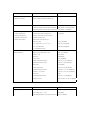
Surround-mode selection depends upon the format of the incoming audio signal as well
as your personal taste. Although there is never a time when all of the AVR’s surround
modes are available, the table below indicates which surround modes are available for
a given input.
To select a surround mode, press the Surround Mode Select buttons. Each press
advances to the next available surround mode.
Input Signal Format
Available Surround Modes
Digital surround-sound modes, such as Dolby Digital and DTS systems, are available only
with specially encoded programs, such as those available via HDTV, DVD and Blu-ray
Disc media and digital cable or satellite television. Other surround modes such as Dolby
Pro Logic II may be used with digital or analog signals to create a different surround
presentation or to use a different number of speakers.
Dolby True HD,
Dolby Digital Plus,
Dolby Digital
(7.1-channel/5.1-channel)
Corresponding Dolby True HD or Dolby Digital mode
(Theater, Hall, Stadium, Club, Arena and 5-Ch Stereo
are also available for 5.1-channel programs)
Dolby Digital (2.0-channel)
Dolby Pro Logic II Movie, Dolby Pro Logic II Music,
Dolby Pro Logic II Game, Dolby Pro Logic
DTS HD Master Audio,
DTS, DTS 96/24
Corresponding DTS Mode (Theater, Hall, Stadium,
Club, Arena and 5-Ch Stereo are also available for
5.1-channel programs)
PCM (2-channel),
Analog (2-channel)
Dolby Pro Logic II Movie, Dolby Pro Logic II Music,
Dolby Pro Logic II Game, Dolby Pro Logic, DTS Neo:6
Cinema, DTS Neo:6 Music, Theater, Hall, Stadium,
Club, Arena, 5-Ch Stereo
MP3/WMA
Dolby Pro Logic II Movie, Dolby Pro Logic II Music,
Dolby Pro Logic II Game, Dolby Pro Logic, DTS Neo:6
Cinema, DTS Neo:6 Music, Theater, Hall, Stadium,
Club, Arena, 5-Ch Stereo
Surround mode selection depends upon the number of speakers in your system, the
programs you are watching or listening to, and your personal tastes.
Advanced Functions
Much of the adjusting and configuration your AVR requires is handled automatically, with
little intervention required on your part. You can also customize your AVR to suit your
system and your tastes. In this section, we will describe some of the more advanced
adjustments available to you.
Audio Processing and Surround Sound
Audio signals can be encoded in a variety of formats that affect not only the quality of the
sound but also the number of speaker channels and the surround mode. You may also
manually select a different surround mode, when available.
Analog Audio Signals
Analog audio signals usually consist of two channels – left and right. Your AVR offers
several options for analog playback:
• Stereo: When you want conventional 2-channel playback, press the STEREO button.
Sound will be output from the front left and right speakers.
• 5-Ch Stereo: When you want to hear stereo sound through all of the system’s speakers
(such as during a party), select 5CH STEREO via the Surround Mode Select buttons.
This plays the left-channel signal through the front left and surround left speakers,
the right-channel signal through the front right and surround right speakers, and a
summed mono signal through the center speaker.
• Analog Surround Modes: Your AVR is able to process 2-channel audio signals to
produce multi-channel surround sound, even when no surround sound has been
encoded in the recording. Among the available modes are Dolby Pro Logic II, Dolby
Pro Logic, DTS Neo: 6, Theater, Hall, Stadium, Club and Arena modes. Use the
Surround Mode Select buttons to select one of these modes. See Table A5 in the
Appendix, on page 25, for breif explanations of each of these surround modes.
When in doubt, check the broadcast or the jacket of your disc for more information
on which surround modes are available. Usually, nonessential sections of a disc, such
as trailers, extra materials or the disc menu, are available only in Dolby Digital 2.0
(2-channel) or PCM 2-channel mode. Look for an audio setup section in the disc’s menu.
Also, make sure your disc player’s audio output is set to the original bitstream rather than
2-channel PCM. Stop play and check the player’s output setting.
Adjusting the Channel Volumes
In addition to using the AVR’s built-in test noise to configure the AVR for your speakers as
explained in Configure the AVR for Your Speakers, you can also adjust the volume of any
channel at any time to compensate for individual program sources or your personal taste.
1. Press the remote’s Channel Level button. The Message Display will show the left
channel volume level.
2. Use the remote’s up and down arrow buttons to display the channel you want to adjust.
3. Use the remote’s left and right arrow buttons to adjust the channel’s volume.
Press the BACK button when you’re finished.
Digital Audio Signals
Recording
Digital audio signals offer greater flexibility and capacity than analog signals and
allow the encoding of up to 5.1 channels of discrete channel information directly into
the signal. The result is improved sound quality and startling directionality, since each
channel’s information is transmitted independently of the other channels. High-resolution
recordings sound extraordinarily distortion-free, especially in the high frequencies.
Two-channel analog audio signals, as well as composite video signals, are normally
available at the appropriate recording output connectors. To make a recording, connect
your audio or video recorder to the appropriate AVR output connectors as described in
the Making Connections section, insert blank media in the recorder and make sure the
recorder is turned on and recording while the source is playing. Refer to the recording
device’s instructions for complete information about making recordings.
Digital surround-sound formats include Dolby Digital 2.0 (two channels only), Dolby
Digital 5.1, Dolby Digital EX (6.1), Dolby Digital Plus (7.1), Dolby TrueHD (7.1), DTSHD High-Resolution Audio (7.1), DTS-HD Master Audio (7.1), DTS 5.1, DTS 96/24 (5.1),
2-channel PCM modes in 44.1kHz, 48kHz, 88.1kHz, 96kHz or 176.4kHz, and 5.1 or
7.1 multichannel PCM. (Your AVR will downmix the discrete surround back-channel
information in 6.1-channel and 7.1-channel recordings into your system’s surround left
and surround right channels.)
NOTES:
1. The AVR does not convert digital signals to analog. Only devices connected to the
analog audio and composite video input connections can be recorded.
2. HDMI video sources are not available for recording.
3. Please make certain that you are aware of any copyright restrictions on any material
you record. Unauthorized duplication of copyrighted materials is prohibited by law.
17
AVR 700/AVR 70/AVR 70C
Advanced Functions, continued
Sleep Timer
To reset the AVR’s processor:
The sleep timer sets the AVR to play for up to 90 minutes and then turn off automatically.
1. Press the front-panel Standby/On switch to place the unit in the Standby mode (the
Standby Indicator LED will turn amber).
Press the Sleep button on the remote, and the time until turn-off will be displayed on
the front-panel Message display The available settings are 30 min., 60 min., 90 min.
and OFF.
When the sleep timer has been set, a small crescent-moon icon will appear on the frontpanel display.
2. Press and hold the front-panel Standby and Memory/Folder buttons until the RESET
message appears on the front-panel Message display.
3. Press the Memory/Folder button again to reset the AVR’s processor.
If you press the Sleep button after the timer has been set, the remaining play time will be
displayed. Press the Sleep button again to change the play time.
If the AVR does not function correctly after a processor reset, contact an authorized
Harman Kardon service center for assistance. To locate an authorized service center,
visit our Web site at www.harmankardon.com.
Processor Reset
Memory
If the AVR behaves erratically after a power surge, first turn off the front-panel Main
Power switch and unplug the AC power cord for at least 3 minutes. Plug the cord back
in and turn the AVR on. If this procedure doesn’t help, reset the AVR’s processor as
described below.
If the AVR is unplugged or experiences a power outage, it will retain your user settings
for up to two weeks.
NOTE: Resetting the processor will erase all user configurations, including speaker and
level settings, and tuner presets. After a reset, reenter all of these settings from your
notes in the Appendix worksheets.
18
AVR 700/AVR 70/AVR 70C
Troubleshooting
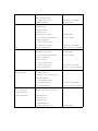
Troubleshooting
Symptom
Cause
Solution
Unit does not function when Main Power switch is
turned on
• No AC power
• Ensure that the power cord is plugged into a live AC
power outlet
• Check if the AC outlet is switch-controlled
Front-panel Message display lights, but there's no
sound or picture
• Intermittent input connection
• Secure all input and speaker connections
• Mute is on
• Press Mute button
• Volume control is turned down
• Turn up Volume control
No sound from any speaker
• Speakers set to “Off” in System Setup menu
• Set speakers to “On” in System Setup menu. See
Additional Setup Menu Items: Speaker On/Off, on
page 15, for more information.
No sound from any speaker; PROTECT message
appears on Message display
• Amplifier is in protection mode due to possible short
circuit
• Check all speaker wires at speaker and AVR
connections for crossed wires
• Amplifier is in protection mode due to internal problems
• Contact your local Harman Kardon service center
• Incorrect surround mode
• Select a surround mode other than stereo
• Program material is monophonic
• Mono programs contain no surround information
• Incorrect speaker configuration
• Check the speaker configuration in the setup menu
• Program material is stereo
• The surround decoder may not create center- or
surround-channel information from nonencoded stereo
programs
• Weak batteries in remote
• Change batteries in remote
• AVR not selected
• Press the Setup/AVR button
• Remote sensor is obscured
• Ensure that the AVR’s front-panel remote sensor is in
the line of sight of the remote
• Local interference
• Move the AVR or antenna away from computers,
fluorescent lights, motors or other electrical appliances
No sound from center or surround speakers
Unit does not respond to remote control commands
Intermittent buzzing in tuner
Additional information on troubleshooting possible problems with your AVR and installation-related issues may be found in the list of “Frequently Asked Questions,” which is located in the Product
Support section of our Web site: www.harmankardon.com
19
AVR 700/AVR 70/AVR 70C
Specifications
Specifications
Audio Section
Multichannel power:
Video Section
75W per channel, two
channels driven @ 6
ohms, 20Hz – 20kHz,
<0.1% THD;
100W per channel, two
channels driven @ 6
ohms, 1kHz, <1% THD
Television format:
NTSC (AVR 700);
PAL (AVR 70/AVR 70C)
Input level/impedance:
1Vp-p/75 ohms
Output level/impedance:
1Vp-p/75 ohms
Video frequency response (composite video):
10Hz – 8MHz (–3dB)
Input sensitivity/impedance:
200mV/47k ohms
HDMI:
With 3D and Deep Color
Signal-to-noise ratio (IHF-A):
95dB
Surround system adjacent-channel separation:
Dolby Pro Logic/PLII:
40dB
Dolby Digital: 55dB
DTS: 55dB
Frequency response:
10Hz – 100kHz
High instantaneous-current capability (HCC):
±25 amps
General Specifications
Power requirement:
120V AC/60Hz (AVR 700)
220V AC/50Hz (AVR 70)
230V AC/50Hz (AVR 70C)
Power consumption:
<0.5W (standby);
280W maximum
Dimensions (W x H x D):
17-5/16" x 4-5/16" x 13"
(440mm x 125mm x 330mm)
Weight
20 lb (9.1kg)
FM Tuner Section
Frequency range:
87.5 – 108.0MHz
Usable sensitivity IHF:
1.3µV/13.2dBf
Signal-to-noise ratio (mono/stereo):
65dB/62dB
Distortion (mono/stereo):
0.2%/0.3%
Stereo separation:
35dB @ 1kHz
Image rejection:
80dB
IF rejection:
80dB
AM Tuner Section
Frequency range:
520 – 1720kHz
Signal-to-noise ratio:
45dB
Usable sensitivity (loop):
500µV
Selectivity (±10kHz):
30dB
20
AVR 700/AVR 70/AVR 70C
Appendix
Appendix – Default settings, worksheets, remote product codes
Table A1 – Recommended Source Component Connections
Device Type
AVR Source
Audio Connections
Video Connections
VCR, DVR, PVR, or other audio/video recorder
Video 1
• Video 1 Analog (inputs and outputs)
• Composite Video 1 Input
• For recording, use Composite Video 1 Output
Cable TV, Satellite, HDTV or other device that
delivers television programs
Video 2
• Video 2 Analog inputs
Composite Video 2 Input
Blu-ray Disc player
HDMI 1
• HDMI 1 Input
• HDMI 1 Input
HDMI-capable disc player, game console or
other audio/video device
HDMI 2
• HDMI 2 Input
• HDMI 2 Input
HDMI-capable disc player, game console or
other audio/video device
HDMI 3
• HDMI 3 Input
• HDMI 3 Input
Portable audio device, camcorder, game console
Video 3
• Video 3 Analog Audio Input on front panel
• Video 3 Coaxial Video Iinput on front panel
CD player
Aux
• Aux Analog Inputs
• Not required
• Optical 1 Input (if not in use)
• Any one available coaxial or optical digital audio
input
Tape
CD-R, MiniDisc, cassette
• Tape Analog (inputs and outputs)
• Not required
Note: Table A1 is a guideline; you may need to make adjustments to fit your system.
Table A2 – Speaker/Channel Settings
Source
Speaker Setting
Left/Right Speaker
Center Speaker
Surround Speakers
Subwoofer
Crossover
Table A3 – Speaker Volume and Distance Settings
Speaker Positions
Channel Volume Setting
Your Distance From Speaker
to Listening Position
Front Left
Center
Front Right
Surround Right
Surround Left
Subwoofer
21
AVR 700/AVR 70/AVR 70C
Appendix
Table A4 – Surround Modes
Surround Mode
Description
Incoming Bitstream or Signal
Dolby Digital
Provides up to five separate main audio channels and a dedicated low-frequency
effects (LFE) channel.
• Dolby Digital 1/0/.0 or .1, 2/0/.0 or .1, 3/0/.0 or .1,
2/1/.0 or .1, 2/2/.0 or .1, 3/2/.0 or .1
• Dolby Digital EX (played as 5.1)
• Dolby Digital Plus decoded and delivered via coaxial or optical
connection
Dolby Digital Plus
An enhanced version of Dolby Digital encoded more efficiently, Dolby Digital Plus
has the capacity for additional discrete channels and for streaming audio from the
Internet, all with enhanced audio quality. Source material may be delivered via an
HDMI connection or decoded to Dolby Digital or PCM and transmitted via coaxial or
optical digital audio.
• Dolby Digital Plus via HDMI connection (source device decodes to
Dolby Digital when a coaxial or optical connection is used)
Dolby TrueHD
Dolby TrueHD is an expansion of MLP Lossless™ audio, the same format used on
DVD-Audio discs. Dolby TrueHD adds the features found in Dolby Digital, such as
night mode settings, while delivering fully lossless audio that is a true reproduction
of studio master recordings.
• Blu-ray Disc or HD-DVD encoded with Dolby TrueHD, delivered
via HDMI
Dolby Digital Stereo
Delivers a 2-channel downmix of Dolby Digital materials.
• Dolby Digital 1/0/.0 or .1, 2/0/.0 or .1, 3/0/.0 or .1,
2/1/.0 or .1, 2/2/.0 or .1, 3/2/.0 or .1
• Dolby Digital EX
Dolby Pro Logic II Mode Group
Analog decoder that derives five full-range, discrete main audio channels from
matrix surround-encoded or 2-channel analog sources. Four variants are available.
See below
Dolby Pro Logic II Movie
Variant of Dolby Pro Logic II that is optimized for movie and television programs.
• Dolby Digital 2.0 or 2.1
• Analog (two-channel)
• Tuner
• PCM (32kHz, 44.1kHz, 48kHz, 96kHz)
• MP3/WMA
Dolby Pro Logic II Music
Variant of Dolby Pro Logic II that is optimized for music selections. Allows
adjustment of sound-field presentation in three dimensions:
• Center Width (adjusts width of vocal soundstage)
• Dimension (adjusts depth of soundstage)
• Panorama (adjusts wraparound surround effect)
• Dolby Digital 2.0 or 2.1
• Analog (two-channel)
• Tuner
• PCM (32kHz, 44.1kHz, 48kHz, 96kHz)
• MP3/WMA
Dolby Pro Logic II Game
Variant of Dolby Pro Logic II that emphasizes use of the surround channels and
subwoofer for total immersion in the video gaming experience.
• Dolby Digital 2.0 or 2.1
• Analog (two-channel)
• Tuner
• PCM (32kHz, 44.1kHz, 48kHz, 96kHz)
• MP3/WMA
Dolby Pro Logic
Original version of Dolby Pro Logic that steered a mono signal containing
information below 7kHz to the surround channels.
• Dolby Digital 2.0 or 2.1
• Analog (two-channel)
• Tuner
• PCM (32kHz, 44.1kHz, 48kHz, 96kHz)
• MP3/WMA
DTS Digital
Using a different encoding/decoding method from Dolby Digital, DTS Digital
also provides up to five discrete main channels, plus an LFE channel.
• DTS 1/0/.0 or .1, 2/0/.0 or .1, 3/0/.0 or .1, 3/1/.0 or .1, 2/2/.0 or
.1, 3/2/.0 or .1
• DTS-ES Matrix (played as 5.1)
• DTS-ES Discrete (played as 5.1)
DTS-HD
DTS-HD is a high-definition audio format that complements the high-definition video
found on Blu-ray Disc and HD-DVD discs. It is transmitted using a DTS core with
high-resolution extensions. Even when only DTS 5.1 surround sound is desired (or
available, if the multizone system is in use), the higher capacity of high-resolution
discs serves up DTS at twice the bit rate used on DVD-Video discs.
• Blu-ray Disc or HD-DVD discs encoded with DTS-HD modes,
delivered via HDMI connection
DTS-HD Master Audio
DTS-HD Master Audio technology delivers bit-for-bit reproductions of studio master
recordings for an incredibly accurate performance.
• Blu-ray Disc or HD-DVD discs encoded with DTS-HD Master
Audio technology, delivered via HDMI connection
22
AVR 700/AVR 70/AVR 70C
Appendix
Table A4 – Surround Modes (cont.)
Surround Mode
Description
Incoming Bitstream or Signal
DTS Stereo
Delivers a 2-channel downmix of DTS Digital materials or presents a matrixencoded surround presentation.
• DTS 1/0/.0 or .1, 2/0/.0 or .1, 3/0/.0 or .1, 3/1/.0 or .1, 2/2/.0 or
.1, 3/2/.0 or .1
• DTS 96/24
• DTS-ES Matrix
DTS Neo:6 Cinema
Delivers an enhanced 5.1-channel surround-sound experience for movies
• Analog (two-channel)
• AM/FM radio
• PCM (32kHz, 44.1kHz, 48kHz, 96kHz)
• MP3/WMA
DTS Neo:6 Music
Delivers an enhanced 5.1-channel surround-sound experience for music
• Analog (two-channel)
• AM/FM radio
• PCM (32kHz, 44.1kHz, 48kHz, 96kHz)
• MP3/WMA
Theater
Creates the effect of being in a large movie theater. Works well with movies.
• Analog (two-channel)
• AM/FM radio
• PCM (32kHz, 44.1kHz, 48kHz, 96kHz)
• MP3/WMA
Hall
Creates the ambience of a concert hall. Good when listening to classical music
sources such as orchestral music, chamber music or instrumental soloists.
• Analog (two-channel)
• AM/FM radio
• PCM (32kHz, 44.1kHz, 48kHz, 96kHz)
• MP3/WMA
Stadium
Creates an expansive soundfield as heard in stadiums. Good for watching sporting
events like baseball or soccer.
• Analog (two-channel)
• AM/FM radio
• PCM (32kHz, 44.1kHz, 48kHz, 96kHz)
• MP3/WMA
Club
Creates the ambience of a club with a low ceiling and hard wall surfaces. Good for
listening to jazz or other intimate musical ensembles.
• Analog (two-channel)
• AM/FM radio
• PCM (32kHz, 44.1kHz, 48kHz, 96kHz)
• MP3/WMA
Arena
Creates a dynamic and broad soundspace that heightens the impact of film
soundtracks and musical performances.
• Analog (two-channel)
• AM/FM radio
• PCM (32kHz, 44.1kHz, 48kHz, 96kHz)
• MP3/WMA
5-Channel Stereo
Useful for parties, the left- and right-channel information is played through both
the front and surround speakers on each side, while the center speaker plays a
summed mono mix.
• Analog (two-channel)
• Tuner
• PCM (32kHz, 44.1kHz, 48kHz, 96kHz)
• MP3/WMA
2-Channel Stereo
Turns off all surround processing and plays a pure 2-channel signal or a downmix
of a multichannel signal. The signal is digitized and bass management settings are
applied, making it appropriate when a subwoofer is used.
• Analog (two-channel; DSP downmix available for multichannel)
• Tuner
• PCM (32kHz, 44.1kHz, 48kHz, 96kHz)
• MP3/WMA
23
AVR 700/AVR 70/AVR 70C
Refer to the numbered buttons when using the Remote Control Function List
24
Appendix
AVR 700/AVR 70/AVR 70C
Appendix
Table A5 – Remote Control Function List
No.
Button Name
AVR Function
Blu-ray/DVD
No.
Button Name
AVR Function
Blu-ray/DVD
01
Power On
Power On
Power On
33
1
1
1
02
Power Off
Power Off
Power Off
34
2
2
2
03
Mute
Mute
Mute
35
3
3
3
04
AVR
AVR Select
AVR Select
36
4
4
4
05
HDMI 1
HDMI 1 Select
HDMI 1 Select
37
5
5
5
06
HDMI 2
HDMI 2 Select
HDMI 2 Select
38
6
6
6
07
HDMI 3
HDMI 3 Select
HDMI 3 Select
39
7
7
7
08
USB
USB Select
USB Select
40
8
8
8
09
VID 1
Video 1 Select
Video 2 Select
41
9
9
9
10
VID 2
Video 2 Select
Video 2 Select
42
0
0
0
11
VID 3
Video 3 Select
Video 3 Select
43
MEMORY
Preset Memory
Find
12
AM/FM
Radio Select
Radio Select
44
Tuning Down
Tuning Down
Program/Red (BD)
13
TV
HDMI ARC Select
HDMI ARC Select
45
Tuning Up
Tuning Up
Bookmark/Green (BD)
14
AUX
Aux
Stereo Mode Select
46
Preset Down
Preset Tune Down
Thumbnail/Yellow (BD)
15
Tape
Tape Select
Tape Select
47
Preset Up
Preset Tune Down
Zoom/Blue (BD)
16
SURR+
Surr Mode Select +
Surr Mode Select +
48
SLEEP/CLEAR
Sleep Timer
Clear
17
STEREO
Stereo Mode Select
Stereo Mode Select
49
Dim
Display Dimmer
Display Dimmer
18
TONE
Tone Controls
Home (BD)
50
Repeat/Random
USB Repeat/Ramdon
Repeat
19
VOL +
Volume Up
Volume Up
51
Skip Down
----
Previous
20
SURR–
Surr Mode Select –
Surr Mode Select –
52
Skip Up
----
Next
21
DISPLAY
Display Mode Select
Display Mode Select
53
Reverse
----
Reverse Search
22
TEST
Test Tone On/Off
Pop-Up Menu
54
Play
----
Play/Reverse
23
VOL–
Volume Down
Volume Down
55
Forward
----
Forward Search
24
DIGITAL
Input Type Select
Options Menu
56
Open/Close
----
Open/Close
25
SETUP
Setup Menu On/Off
Settings (BD) Setup (DVD)
57
Stop
----
Stop
26
Up
Move/Adust Up
Up
58
Pause
----
Pause
27
Left
Move/Adjust Left
Left
28
OK
OK
Enter
29
Right
Move/Adjust Right
Right
30
Down
Move/Adjust Down
Down
31
BACK
Previous Menu
Exit (BD)
32
CHANNEL
Channel Level Adjust
Top Menu Display (BD)
25
FPO
HARMAN International Industries, Incorporated
8500 Balboa Boulevard, Northridge, CA 91329 USA
© 2012 HARMAN International Industries, Incorporated. All rights reserved.
Harman Kardon is a trademark of HARMAN International Industries, Incorporated, registered in the United States and/or other countries.
Blu-ray Disc is a trademark of the Blu-ray Disc Association.
CEA is a registered trademark of the Consumer Electronics Association.
Manufactured under license from Dolby Laboratories. Dolby, the double-D symbol and Pro Logic are registered trademarks of Dolby
Laboratories. MLP Lossless is a trademark of Dolby Laboratories.
Manufactured under license under U.S. Patent Nos: 5,956,674; 5,974,380; 6,226,616; 6,487,535; 7,212,872; 7,333,929; 7,392,195;
7,272,567 & other U.S. and worldwide patents issued &pending. DTS-HD, the Symbol, & DTS-HD and the Symbol together are registered
trademarks of DTS, Inc. © DTS, Inc. All Rights Reserved.
HDMI, the HDMI logo and High-Definition Multimedia Interface are registered trademarks of HDMI Licensing LLC in the United States and
other countries.
Features, specifications and appearance are subject to change without notice.
HKP4078 Rev. 1
www.harmankardon.com
AVR70/700/70C TROUBLESHOOTING
Symptom
Cause and Remedy
Power On Failure
A) AC-Cord check.
1. FLT does not light up.
B) Power Trans (Main/ST-BY) check.
2. ST-BY LED does not light up.
C) Fuse's disconnection check.
Ref No.
F300(STANDBY)
D) Connector's disconnection or disjunction.
Change or close insertion of the connector.
CP704,FPC100(FRONT)
E) Inferior ST-By switch.
SW(700)(FRONT)
F) VFD Driver I.C & Resonator check.
I.C701 SC16315(FORNT)
1. VFD Driver I.C VCC(+3.3)V check.
I.C701 Pin No13(FRONT)
2. VFD Driver clock pulse check.
I.C701 Pin No5(FRONT)
Fuse Disconnection.
A) Inferior transformer.
(Power On)
B) AMP drive TR out. (POWER TR)
Q206( FL, FR, C, SL, SR )(AMP)
C) AMP drive TR out. ( POWER TR )
Q205 ( FL, FR, C, SL, SR ) (AMP)
D) voltage check.
1. B+ ( 47 )V, B- ( 47 ) V
Key Disorder.
A) Key's being pushed check.
B) Key signal input components inferior.
C) Key PORT check.
I.C119 Pin No. (91,92 )(DMAIN)
D) μ-COM I.C inferior.
1. μ-COM IC VCC +3.3V check.
Power Off in 2~3 sec.
after Power On.
A) Regulator I.C out.
I.C119 Pin No. ( 16,62 )(DMAIN)
I.C 300 (IL1117S_3.3V)(STANDBY)
1. Signal IN/OUT check.
B) Drive transistor out. ( POWER TR )
Q205 ( FL, FR, C, SL, SR ) (AMP)
Q206( FL, FR, C, SL, SR )(AMP)
C) Protection circuit check.
1. Output DC check.
2. μ-COM I.C protection terminal check.
D) Connector's disconnection or disjunction
u-COM Pin No. ( 85 )(DMAIN)
CP (111)(MAIN)
E) SLEEP MODE cancellation.
Bump Sound
(During input-select switch's change.)
A) FRONT Mute transistor's out and inferior.
μ-Com front mute control PORT check.
B) CENTER Mute transistor's out and inferior.
μ-Com center mute control PORT check.
D) SURROUND Mute transistor's out and inferior.
μ-Com surround mute control PORT check.
Q (105 ) (MAIN)
I.C119 Pin No. ( 2 )(DMAIN)
Q ( 107 )(MAIN)
I.C119 Pin No. ( 97 )(DMAIN)
Q ( 109 )(MAIN)
I.C119 Pin No. ( 1 )(DMAIN)
To check software version: Switch AVR 70 into Standby (LED lights amber),
Keep "Standby" and "Preset Down" buttons pressed at the same time until
display shows software version (such as "70 E0.65").
Symptom
Sounds from Speaker when
Headphone's connected.
Bass / Treble Control Failure.
Cause and Remedy
Ref No.
A) NOT Supported Headphone Detect.
Push the Speaker On/Off Button(Speaker off).
A) Volume IC check.
1. Resister/Capacitor correction figure check.(Bass)
I.C109(MAIN)
I.C109 PIN No. ( 26,27,32,33)(MAIN)
2. Resister/Capacitor correction figure check.(Treble) I.C109 PIN No. ( 28,34)(MAIN)
AMP Sound Dead.
A) Signal Mute TR's inferior.
Q 105,107,109(MAIN)
1. "LEFT" Channel dead.
B) Connector disconnection & disjunction.
CP111(MAIN)
2. "RIGHT" Channel dead.
3. "CENTER" Channel dead.
4. "REAR" Channel dead.
Change or close insertion of the connector.
C) Speaker wire's disjunction.
Close insertion of the speaker wire.
D) Volume IC check.
I.C No. ( 109 )(MAIN)
1. I.C voltage check ( +7.5 )V, ( -7.5 )V
I.C Pin No. ( 30,52)(MAIN)
2. I.C control data check.
I.C PIN No. (49,50)(MAIN)
3. I.C signal IN/OUT check.
AC-3/DTS Failure.
(DSP Sound Mode)
A) I.C Regulator check.
DSP I/O + (3.3)V,DSP CORE + (1.2)V
I.C110, I.C111(DMAIN)
CODEC + ( 5)V
I.C111 (MAIN)
B) DIR check.
I.C109(DMAIN)
1. OSC check.
X-TAL 102(DMAIN)
2. BICK, LRCK, RDATA Check.
I.C Pin No. ( 15, 16, 14)(DMAIN )
3. Micom Interface Port Check.
I.C Pin No. ( 21,22,31 )(DMAIN)
C) DSP Check.
I.C117(DMAIN)
1. BICK, LRCK Check.
I.C Pin No. ( 162, 163 )(DMAIN)
2. Micom Interface Port Check.
I.C Pin No.(7, 8, 13, 14, 146)(DMAIN)
3. SDATA 1, 2, 3,4 Check.
I.C Pin No. (1, 174, 175, 176)(DMAIN)
D) D/A Check.
Symptom
Video Output Dead.
I.C109
1. LRCK/BCK/SDATA check.
I.C Pin No. ( 17,18,19)(DMAIN)
2. Signal out check.
I.C Pin No. (39, 41, 43, 45, 47, 49)(DMAIN
Cause and Remedy
Ref No.
A) Video Regulator voltage check.
1. DC voltage check. + ( 12 )V
B) Video Mute(MONTOR,V1 OUT) port check.(IC101)
I.C110 (MAIN)
I.C119 ( 23 )(DMAIN)
Remote Controller Failure.
A) Battery check.
B) RMC I.C & Resonator inferior.
FM Failure.
1. μ-COM I.C B+( 3.3 )V check.
I.C119 Pin No. ( 16,62 )(DMAIN)
2. REMOCON data check.
RMC701(1) (FRONT)
A) FM MUTE adjustment inferior.
B) FRONT-END inferior.
C) FM DET COIL inferior.
D) PLL&MPX IC check.
1. PLL&MPX I.C B+( 5 )Vcheck.
PACK102( 6 )(MAIN)
2. PLL control data check. (Data/CE/Clock)
pack102(3, 4, 5)(MAIN)
E) TUNER B+ voltage inferior.
F) μ-COM I.C & Resonator inferior.
AM Failure.
1. μ-COM I.C B+( 3.3 )V check.
I.C119 Pin No. ( 16,62 )(DMAIN)
2. Micom control data check.
I.C Pin No. ( 18, 40, 42, 43, 44)(DMAIN)
A) PLL&MPX IC check.
1. PLL&MPX I.C B+( 5 )Vcheck.
PACK102( 6 )(MAIN)
2. PLL control data check (Data/CE/Clock)
pack102(3, 4, 5)(MAIN)
B) TUNER B+ voltage inferior.
C) AM OSC COIL inferior.
D) μ-COM I.C & Resonator inferior.
1. μ-COM I.C B+( 3.3)V check.
I.C119 Pin No. ( 16,62 )(DMAIN)
2. Micom control data check.
I.C Pin No. ( 18, 40, 42, 43, 44)(DMAIN)
Stereo Effect Failure.
A) FM DET COIL Inferior.
Stereo does not light up.
B) PLL&MPX IC check.
1. PLL&MPX I.C B+( 5 )V,B+( 3.3 )V check.
2. MPX control data check.
C) μ-COM I.C & Resonator inferior.
Tuner Sound Dead.
1. "L / R" Channel dead.
1. μ-COM IC B+( 3.3)V check
I.C119 Pin No. ( 16,62 )(DMAIN)
2. Micom control data check.
I.C Pin No. ( 18, 40, 42, 43, 44)(DMAIN)
A) Connector's disconnection or disjunction.
Change or Close insertion of the connector.
2. "LEFT" Channel dead.
3. "RIGHT" Channel dead.
B) FM DET COIL inferior.
C) AM IFT COIL inferior.
D) PLL&MPX IC check.
1. Signal IN/OUT terminal.
2. I.C driving voltage check. ( +5V)
PACK102( 6 )(MAIN)
PRIMARY AVR 70 PARTS LIST
Please order the below parts using these numbers, not the
numbers in the long parts list
Part number
Description
7025HK1121020
AVR70(HARMAN)/MAIN
7025HK1121021
AVR70(HARMAN)/HDMI
7025HK1121022
AVR70(HARMAN)/AMP
7025HK1121023
AVR70(HARMAN)/FRONT
7025HK1121024
AVR70(HARMAN)/STANDBY
7025HK1121025
AVR70(HARMAN)/CNT
8200858630570S
8200280150410S
8300880000010S
30070412360H0S
3067213971110S
5630210828000S
5630210818000S
5097213641100S
3207214296010S
3710210793000S
4000040201010S
4007040201060S
5080211793000S
5077212543020S
5080211793000S
5087211781100S
5097213651100S
5200210262000S
6007212260010S
POWER TRANSFORMER AVR 70/230
STAND-BY TRANSFORMER AVR 70/230V
REMOTE CONTROL AVR 70/230
TOP COVER AVR70/230
FRONT (PLASTIC) PANEL AVR 70/230
LOGO BADGE 'AVR 70'
LOGO BADGE 'Harman /kardon' AVR 70
STBY BUTTON AVR133/134
REAR PANEL AVR 70/230
STANDBY LENS AVR 70 /230
FOOT RUBBER
FOOT
PLATE KNOB VOLUME BK
FRONT WINDOW ACRY AVR70
KNOB VOLUME MILKY
KNOB VOLUME CAP AVR 70
FUNCTION BUTTON (7)
FILTER FIP, WINE COLOR
GIFT BOX BEAUTY CARTON AVR 70/230
AVR 70 amplifier board parts list
REF NO.
PCB
PCB
PCB
PCB
PCB
PCB
P.C.B TOTAL ASSY
P.C.B SUB ASSY
P.C.B
P.C.B INS ASSY
P.C.B INS ASSY
P.C.B INS ASSY
DESCRIPTION
AMP
AMP
AMP
AVR133(HARMAN)/AMP-AXIAL
AVR133(HARMAN)/AMP-MANUAL
AVR133(HARMAN)/AMP-RADIAL
L201C/FL/FR/SL/SR
COIL,FILTER-INDUCTOR
COILS
SP-2507 1.0 PI*2UEW TURNS=7T SPRING COIL
5 D330900001330S
CN101
CN102
CN,WIRE 2MM
CN,WIRE
CONNECTOR
100MM/10P 20010HS-10=CKM2002HV-10 WH1007#26 연접
80MM/12P 5264-12=CKM2509H-12 WH1007#26 연접
1 L002-10110-006-0S
1 L000-80012-005-0S
C211C/FL/FR/SL/SR
C206C/FL/FR/SL/SR
C202C/FL/FR/SL/SR
C204C/FL/FR/SL/SR
C209C/FL/FR/SL/SR
C210C/FL/FR/SL/SR
C203C/FL/FR/SL/SR
C201C/FL/FR/SL/SR
C208C/FL/FR/SL/SR
C212
C205C/FL/FR/SL/SR
C207C/FL/FR/SL/SR
C,CERAMIC HIK AXIAL
C,CERAMIC HIK AXIAL
C,CERAMIC HIK AXIAL
C,CERAMIC T.C DISC
C,CERAMIC HIK DISC
C,CERAMIC HIK DISC
C,CERAMIC-UNKNOWN
C,ELECT GE 85C
C,ELECT GE 85C
C,ELECT GE 85C
C,ELECT GE 85C
C,ELECT GE 85C
CAPACITOR
UP025 F223Z-B-BZ
UP025 B102K-B-BZ
UP025 B681K-B-BZ
SL33PF-J/500V-5RE CC1-L5N7505B330JTPW
B100PF-K/500V-5RE CT1-L5S2L5B101KTP
B100PF-K/500V-5RE CT1-L5S2L5B101KTP
CAP C 220PF 500V-5RE
10UF-M/50V,5*11-5RE.SMS SY
10UF-M/50V,5*11-5RE.SMS SY
10UF-M/100V,6.3*11-5RE,SMS SY
100UF-M/10V,5*11-5RE.SMS SY
47UF-M/50V,6.3*11-5RE.SMS SY (Pb Free)
5
5
5
5
5
5
5
5
5
1
5
5
D201C/FL/FR/SL/SR
D,SWITCHING
DIODES
1SS133T-72-52MM
5 K000013300520S
Q201C/FL/FR/SL/SR
Q202C/FL/FR/SL/SR
Q203C/FL/FR/SL/SR
Q207C/FL/FR/SL/SR
SEMI,TR/GE PNP 2SA
SEMI,TR/GE PNP 2SA
SEMI,TR/GE NPN 2SC
SEMI,TR/GE NPN 2SC
TRANSISTOR
KSA992F,0.5W/TO92-REEL
KSA992F,0.5W/TO92-REEL
KTC3200BL,0.6W/TO92-REEL
KTC3200BL,0.6W/TO92-REEL
5
5
5
5
R209C/FL/FR/SL/SR
R207C/FL/FR/SL/SR
R201C/FL/FR/SL/SR
R227C/FL/FR/SL/SR
R224C/FL/FR/SL/SR
R214C/FL/FR/SL/SR
R206C/FL/FR/SL/SR
R225C/FL/FR/SL/SR
R204C/FL/FR/SL/SR
R210C/FL/FR/SL/SR
R208C/FL/FR/SL/SR
R205C/FL/FR/SL/SR
R213C/FL/FR/SL/SR
R203C/FL/FR/SL/SR
R226C/FL/FR/SL/SR
R212C/FL/FR/SL/SR
R228C/FL/FR/SL/SR
R229
R211C/FL/FR/SL/SR
R216C/FL/FR/SL/SR
R217C/FL/FR/SL/SR
R218C/FL/FR/SL/SR
R219C/FL/FR/SL/SR
R220C/FL/FR/SL/SR
R221C/FL/FR/SL/SR
R222C/FL/FR/SL/SR
R223C/FL/FR/SL/SR
J204/J206/J208
J210-J214
J216/J218
J222-J231
J233/J234/J238
J241/J242
J246-J253
J255-J266
J268/J269
J271-J308
J314/J315
R,CARBON FILM
R,CARBON FILM
R,CARBON FILM
R,CARBON FILM
R,CARBON FILM
R,CARBON FILM
R,CARBON FILM
R,CARBON FILM
R,CARBON FILM
R,CARBON FILM
R,CARBON FILM
R,CARBON FILM
R,CARBON FILM
R,CARBON FILM
R,CARBON FILM
R,CARBON FILM
R,METAL FILM 100PPM
R,METAL FILM 100PPM
R,METAL FILM 100PPM
R,METAL FILM 100PPM
R,METAL FILM 100PPM
R,METAL FILM 100PPM
R,METAL FILM 100PPM
R,METAL FILM 100PPM
R,METAL FILM 100PPM
R,METAL FILM 100PPM
R,METAL FILM 100PPM
CN,WIRE 1P
CN,WIRE 1P
CN,WIRE 1P
CN,WIRE 1P
CN,WIRE 1P
CN,WIRE 1P
CN,WIRE 1P
CN,WIRE 1P
CN,WIRE 1P
CN,WIRE 1P
CN,WIRE 1P
RESISTOR
1.2K-J , 1/5W
1.5K-J , 1/5W
220-J , 1/5W
2.2K-J , 1/5W
27K-J , 1/5W
3K-J , 1/5W
33K-J , 1/5W
330K-J , 1/5W
39K-J , 1/5W
470-J , 1/5W
47K-J , 1/5W
470K-J , 1/5W
56-J , 1/5W
7.5K-J , 1/5W
75K-J , 1/5W
910-J , 1/5W
RES MF 10 OHM 1W
10-J , 1W
47-J , 1/4W
5.6K-J , 1W
5.6K-J , 1W
4.7-J , 1/4W
4.7-J , 1/4W
0.47-J , 2W
0.47-J , 2W
0.47-J , 2W
0.47-J , 2W
0.6/52MM
0.6/52MM
0.6/52MM
0.6/52MM
0.6/52MM
0.6/52MM
0.6/52MM
0.6/52MM
0.6/52MM
0.6/52MM
0.6/52MM
Q'TY
1
1
1
1
1
1
5
5
5
5
5
5
5
5
5
5
5
5
5
5
5
5
5
1
5
5
5
5
5
5
5
5
5
3
5
2
10
3
2
8
12
2
38
2
PART NO.
7025-HK112-101-2
7028-06684-101-0
7020-06684-000-0S
7027-06684-1A1-0
7027-06684-1M1-0
7027-06684-1R1-0
D005-22359-452-1S
D005-10217-753-1S
D005-68117-752-1S
D000-33006-D05-1S
D004-10107-D05-1S
D004-10107-D05-1S
D009-09221-250-0S
D040-10008-707-0S
D040-10008-707-0S
D040-10008-C05-0S
D040-10108-209-0S
D040-47008-707-0S
J5000992F0050S
J5000992F0050S
J5023200B0050S
J5023200B0050S
C000-01226-P52-0S
C000-01526-P52-0S
C000-02216-P52-0S
C000-02226-P52-0S
C000-02736-P52-0S
C000-03026-P52-0S
C000-03336-P52-0S
C000-03346-P52-0S
C000-03936-P52-0S
C000-04716-P52-0S
C000-04736-P52-0S
C000-04746-P52-0S
C000-05606-P52-0S
C000-07526-P52-0S
C000-07536-P52-0S
C000-09116-P52-0S
C060-01006-552-0S
C060-01006-505-0S
C060-04706-305-0S
C060056265050S
C060-05626-505-0S
C060-4R706-305-0S
C060-4R706-305-0S
C060R47066050S
C060-R4706-605-0S
C060-R4706-605-0S
C060-R4706-605-0S
L045-08400-604-0S
L045-08400-604-0S
L045-08400-604-0S
L045-08400-604-0S
L045-08400-604-0S
L045-08400-604-0S
L045-08400-604-0S
L045-08400-604-0S
L045-08400-604-0S
L045-08400-604-0S
L045-08400-604-0S
AVR 70 control board parts list
REF NO.
PCB
PCB
PCB
PCB
PCB
PCB
PCB
P.C.B TOTAL ASSY
P.C.B SUB ASSY
P.C.B
P.C.B INS ASSY
P.C.B INS ASSY
P.C.B INS ASSY
P.C.B INS ASSY
DESCRIPTION
CNT
CNT
CNT
CNT-AXIAL
CNT-MANUAL
CNT-RADIAL
CNT-SMD
CN101/CN102
CN105/CN106
CN100
CN104
CN,WAFER
CN,WAFER
CN,WAFER
CN,WAFER
C125Z1-19
C125Z2-19
C125Z1-25
C125Z2-25
C653/C667
C678/C683
C650/C652
C647
C665/C668/C669
C680/C682
C672/C679/C681/C684
C658
C657
C,ELECT GE 85C
C,ELECT GE 85C
C,ELECT GE 85C
C,CERAMIC CHIP T.C
C,CERAMIC CHIP T.C
C,CERAMIC CHIP T.C
C,CERAMIC CHIP T.C
C,CERAMIC CHIP T.C
C,CERAMIC CHIP HIK
D566/D567
Q'TY
1
1
1
1
1
1
1
PART NO.
7025-HK112-101-5
7028-07210-101-0
7020-07210-000-0S
7027-07210-1A1-0
7027-07210-1M1-0
7027-07210-1R1-0
7027-07210-1S1-0
2
2
1
1
L109-01251-191-0S
L109-01252-191-0S
L109-01251-251-0S
L109-01252-251-0S
1UF-M/50V,5*11-5RE.SMS SY (Pb Free)
10UF-M/16V,3*5-5RE SY
10UF-M/50V,5*11-5RE.SMS SY
X7R 0.01UF-K/50V-1608REEL
X7R 0.01UF-K/50V-1608REEL
X7R 0.01UF-K/50V-1608REEL
COG33PF-J/50V-1608REEL
COG 680pF-J 50V-1608REEL
X7R3300PF-K/50V-1608REEL
2
2
2
1
3
2
4
1
1
D040-01008-715-0S
D040-10008-305-0S
D040-10008-707-0S
D010-10377-716-0S
D010-10377-716-0S
D010-10377-716-0S
D010-33016-716-0S
D010-68116-716-0S
D011-33277-716-0S
D,SWITCHING CHIP
1N4148WS FAST SWITCHING DOIDE Trr=4ns SOD-323
2 K005-04148-323-0S
IC558/IC560/IC561
Q583
Q580
Q581/Q582
IC,LINEAR OP
SEMI,CHIP TR/PNP 2SA
SEMI,CHIP TR/NPN 2SC
SEMI,FET/2SN
UTC4580E SOP8 DUAL OP AMP
RT1P141C 0.2W/SC-59 ISAHAYA
RT1N441C 0.2W/SC-59 ISAHAYA
2SK492C N-CH FET SC-59 ISAHAYA
3
1
1
2
J121-45800-101-0S
J520-10141-121-0S
J522-10441-121-0S
J544-04920-121-0S
R692/R702
R676
R707
R705/R710
R701/R703/R706/R709
R711/R712
R680
R669/R671
R708
R677
R689/R704
J107
R672
R679
J101-J104/J106
R,CARBON FILM
R,CARBON FILM
R,CARBON FILM
R,CARBON FILM
R,CHIP THICK
R,CHIP THICK
R,CHIP THICK
R,CHIP THICK
R,CHIP THICK
R,CHIP THICK
R,CHIP THICK
R,CHIP THICK
R,CHIP THICK
R,CHIP THICK
CN,WIRE 1P
10K-J,1/5W-52RE-AX
100K-J,1/5W-52RE-AX
2.2K-J,1/5W-52RE-AX
9.1K-J,1/5W-52RE-AX
10K-J,1/16W-1608REEL
10K-J,1/16W-1608REEL
100K-J,1/16W-1608REEL
4.7K-J,1/16W-1608REEL
470K-J,1/16W-1608REEL
5.6K-J,1/16W-1608REEL
91K-J,1/16W-1608REEL
0-J,1/8W-3216REEL
1K-J,1/16W-1608REEL
1.8K-J,1/16W-1608REEL
JUMPER (0.6/52MM)
2
1
1
2
4
2
1
2
1
1
2
1
1
1
5
C000-01036-P52-0S
C000-01046-P52-0S
C000-02226-P52-0S
C000-09126-P52-0S
C200-01036-M16-0S
C200-01036-M16-0S
C200-01046-M16-0S
C200-04726-M16-0S
C200-04746-M16-0S
C200-05626-M16-0S
C200-09136-M16-0S
C200-00006-130-0S
C200-01026-M16-0S
C200-01826-M16-0S
L045-08400-604-0S
PCB
PCB
P.C.B SUB ASSY
P.C.B INS ASSY
AVR700(HARMAN)/CNT2
AVR700(HARMAN)/CNT2-MANUAL
1 7028-07210-201-0
1 7027-07210-2M1-0
CN103
CN107
CN.WAFER
CN.WAFER
C125Z1-29 29P BtoB HEADER(MALE) P=1.25MM
C125Z2-29 29P BtoB SOCKET(FEMALE) P=1.25MM
1 L109-01251-291-0S
1 L109-01252-291-0S
19P BtoB HEADER(MALE) P=1.25MM
19P BtoB SOCKET(FEMALE) P=1.25MM
25P BtoB HEADER(MALE) P=1.25MM
25P BtoB SOCKET(FEMALE) P=1.25MM
AVR 70 front board parts list
REF NO.
PCB
PCB
PCB
PCB
PCB
PCB
PCB
P.C.B TOTAL ASSY
P.C.B SUB ASSY
P.C.B
P.C.B INS ASSY
P.C.B INS ASSY
P.C.B INS ASSY
P.C.B INS ASSY
DESCRIPTION
FRONT
FRONT
AVR133(HARMAN) 330*247 1.6T FR1 ARRY(2)/FRONT
FRONT-AXIAL
FRONT-MANUAL
FRONT-RADIAL
FRONT-SMD
CB701-CB704
L702
L700
L703/L704
COIL,BEAD
COIL,FILTER-INDUCTOR
COIL,FILTER-INDUCTOR
COIL,FILTER-INDUCTOR
C707/C710
C708/C709/C731
C735L/R
C721
C703/C717
C728
C743-C745
C734/C726/C727
C718/C719
C714-716
C713L/R
C704-C706
C,FILM POLYESTER
C,ELECT GE 85C
C,ELECT GE 85C
C,ELECT GE 85C
C,ELECT GE 85C
C,CERAMIC HIK AXIAL
C,CERAMIC CHIP T.C
C,CERAMIC CHIP T.C
C,CERAMIC CHIP HIK
C,CERAMIC CHIP HIK
C,CERAMIC CHIP HIK
C,CERAMIC CHIP HIK
Q'TY
1
1
1
1
1
1
1
PART NO.
7025-HK112-101-3
7028-06685-501-0
7020-06685-000-2S
7027-06685-5A1-0
7027-06685-5M1-0
7027-06685-5R1-0
7027-06685-5S1-0
CBW160808U121T 120ohm SMD1608 TYPE
10UH-Q40/24M-R2.5-52RE 02TB
100UH-Q40/9M-R12-52RE 02TB
2.2UH-Q50/110M-R1.2 52RE-AXIAL LAL03TB
4
1
1
2
D340-16081-121-0S
D330-10070-052-0S
D330-10100-102-0S
D330-2R200-052-0S
ST-0.047UF-J/100V-5RE
10UF-M/50V,5*11-5RE.SMS SY
10UF-M/50V,5*11-5RE.SMS SY
100UF-M/10V,5*11-5RE.SMS SY
47UF-M/16V,5*7-5RE SRA SY
UP025 B103K-B-BZ
COG100PF-J/50V-1608REEL
X7R 0.01UF-K/50V-1608REEL
X7R0.1UF-K/50V-1608REEL
X7R0.1UF-K/50V-1608REEL
X7R470PF-K/50V-1608REEL
X7R820PF-K/50V-1608REEL
2
3
2
1
2
1
3
3
2
3
2
3
D02047306C060S
D040-10008-707-0S
D040-10008-707-0S
D040-10108-207-0S
D040-47008-306-0S
D005-10377-353-1S
D010-10116-716-0S
D010-10377-716-0S
D011-10457-716-0S
D011-10457-716-0S
D011-47176-716-0S
D011-82177-716-0S
AVR 70 front board parts list
REF NO.
CN707
J700-J714
CN,WIRE 2MM
CN,WIRE 1P
DESCRIPTION
250/5P 20010HS-05=CKM2002H-05 WH2547,1533#26SHLD
JUMPER (0.6/52MM)
CP704
CP701
FPC701
CN.WAFER 2.5MM
CN.WAFER 2.0MM
CN.FPC 1.25MM
5268-03A 3P ANGLE
20010WS-04A00 DIP4P STRAIGHT
1.25-2S-17PW 17P AN DIP
1 L102-52680-301-0S
1 L101-20010-041-0S
1 L131-12502-172-0S
DZ705
D701-D704
D,ZENER
D,SWITCHING CHIP
MTZJ7.5B-0.5W/5MA-52MM
1N4148WS FAST SWITCHING DOIDE Trr=4ns SOD-323
1 K06007R544520S
4 K005-04148-323-0S
Q703
Q701/Q704
SEMI,CHIP TR/PNP 2SA
SEMI,CHIP TR/NPN 2SC
KRA105S(PE) 0.2W/SOT-23 REEL
KRC105S (NE) 0.2W/SOT-23 REEL
1 J520-01050-021-0S
2 J522-01050-021-0S
IC701
IC,LINEAR-DRIVER
SC16315 VFD DRIVER CONTROLLER IC QFP44P
1 J127163150010S
R755/R757
R752/R754
R749/R751
R782L/R
R744/R747
R784L/R
R742/R760
R704-R731
R702/R703
R732/R733
R743
R748/R758/R759
R737
R771
R739/R471/R774
J713
R745
R,CHIP THICK
R,CHIP THICK
R,CHIP THICK
R,CHIP THICK
R,CHIP THICK
R,CHIP THICK
R,CHIP THICK
R,CHIP THICK
R,CHIP THICK
R,CHIP THICK
R,CHIP THICK
R,CHIP THICK
R,CHIP THICK
R,CARBON FILM
R,CARBON FILM
R,CHIP THICK
R,CHIP THICK
1K-J,1/16W-1608REEL
1.5K-J,1/16W-1608REEL
2.2K-J,1/16W-1608REEL
100K-J,1/16W-1608REEL
3.3K-J,1/16W-1608REEL
470-J,1/16W-1608REEL
4.7K-J,1/16W-1608REEL
56K-J,1/16W-1608REEL
68K-J,1/16W-1608REEL
68K-J,1/16W-1608REEL
75-J,1/16W-1608REEL
200-J,1/16W-1608REEL
82K-J,1/16W-1608REEL
15K-J,1/5W-52RE-AX
470-J,1/5W-52RE-AX
0-J,1/8W-3216REEL
0-J,1/16W-1608REEL
FLT701
RMC701
VR701
JACK700
HOLDER
LED701/LED703/LED704
SW705/SW706
SW708/SW709
SW711/SW712
SW714/SW715
SW718-SW720
DISPLAY,FLT
MODULE,REMOCON
SW,ENCODER
TER,RCA 3PIN
HOLDER
LED,ROUND
SW,TACT
SW,TACT
SW,TACT
SW,TACT
SW,TACT
PCB
PCB
PCB
Q'TY PART NO.
1 L002-25105-007-0S
15 L045-08400-604-0S
2
2
2
2
2
2
2
28
2
2
1
3
1
1
3
1
1
C200-01026-M16-0S
C200-01526-M16-0S
C200-02226-M16-0S
C200-01046-M16-0S
C200-03326-M16-0S
C200-04716-M16-0S
C200-04726-M16-0S
C200-05636-M16-0S
C200-06836-M16-0S
C200-06836-M16-0S
C200-07506-M16-0S
C200-02016-M16-0S
C200-08236-M16-0S
C000-01536-P52-0S
C000-04716-P52-0S
C200-00006-130-0S
C200-00006-M16-0S
SPC08.03.13-02 12G*16A 110*29 GREEN/AVR133
R34FS9A 38KHZ IR REMOCON MODULE P=2.54MM H=15MM
REB12307PVB25FINB1-2-24E 24PULSES
RCA-326H-02(YL,WH,RD)
() HOLDER FL(PC)HK-3250
WEJ51BWW-C53 5PI WHITE P=2.54 BULK
SKHV10920A,5MM/260G-REEL
SKHV10920A,5MM/260G-REEL
SKHV10920A,5MM/260G-REEL
SKHV10920A,5MM/260G-REEL
SKHV10920A,5MM/260G-REEL
1
1
1
1
1
3
2
2
2
2
2
K530-08030-001-0S
E940-34900-381-0S
G121123070020S
G606-326H0-200-YS
4320-04078-301-AS
K500-05900-111-0S
G180000270010S
G180000270010S
G180000270010S
G180000270010S
G180000270010S
P.C.B SUB ASSY
P.C.B INS ASSY
P.C.B INS ASSY
AVR700(HARMAN)/HEADPHONE
AVR700(HARMAN)/HEADPHONE-MANUAL
AVR700(HARMAN)/HEADPHONE-SMD
1 7028-06685-601-0
1 7027-06685-6M1-0
1 7027-06685-6S1-0
JACK701
CN702
LUG703
JACK,D6.5
CN,WIRE 2MM
RING,TER WIRE
PHONE (YUQIU) D6.5 SILVER
330MM/4P 20010HS-04=CKM2002HV-04 WH2547#26 SHIELD
190MM/1P 61640BS(3.2PI)=B1813TOP BK1007#18
1 G402PJ619A01YS
1 L002-33104-001-0S
1 8410-19101-003-0S
C712L/R
CB707-CB709
C711
C712
C713
C,CERAMIC CHIP T.C
COIL,BEAD
C,CERAMIC CHIP HIK
C,CERAMIC CHIP HIK
C,CERAMIC CHIP T.C
X7R 0.01UF-K/50V-1608REEL
CBW160808U121T 120ohm SMD1608 TYPE
X7R0.1UF-K/50V-1608REEL
X7R470PF-K/50V-1608REEL
X7R 0.01UF-K/50V-1608REEL
2
3
1
1
1
PCB
PCB
P.C.B SUB ASSY
P.C.B INS ASSY
AVR700(HARMAN)/POWER SW
AVR700(HARMAN)/POWER SW-MANAUL
1 7028-06685-701-0
1 7027-06685-7M1-0
SW701
CN705
SW,PUSH
CN,WIRE
SDDL-005-S(C-UL)
420MM/2P 35191-02=CKM99050101-03 BK/RD1617#22
1 G000122006060S
1 L000-42102-003-0S
PCB
PCB
PCB
PCB
P.C.B SUB ASSY
P.C.B INS ASSY
P.C.B INS ASSY
P.C.B INS ASSY
AVR700(HARMAN)/STANDBY SW
AVR700(HARMAN)/STANDBY-MANAUL
AVR700(HARMAN)/STANDBY-RADIAL
AVR700(HARMAN)/STANDBY-SMD
1
1
1
1
7028-06685-801-0
7027-06685-8M1-0
7027-06685-8R1-0
7027-06685-8S1-0
CN701
LED702/LED705
SW700
R746/R750
Q702
CN,WIRE 2MM
LED,ROUND
SW,TACT
R,CHIP THICK
SEMI,CHIP TR/NPN 2SC
60MM/4P 20010HS-04=CKM2002HV-04 WH1007#26 연접
SLI-343D8UT32XK 3PI AMBER P=2.5
SKHV10920A,5MM/260G-REEL
120-J,1/16W-1608REEL
KRC105S (NE) 0.2W/SOT-23 REEL
1
3
1
2
1
L002-60004-006-0S
K500033000040S
G180-00027-001-0S
C200-01216-M16-0S
J522-01050-021-0S
D010-10377-716-0S
D340-16081-121-0S
D011-10457-716-0S
D011-47176-716-0S
D010-10377-716-0S
AVR 70 HDMI board parts list
REF NO.
PCB
PCB
PCB
PCB
PCB
P.C.B TOTAL ASSY
P.C.B SUB ASSY
P.C.B
P.C.B INS ASSY
P.C.B INS ASSY
DESCRIPTION
HDMI
HDMI
HDMI
HDMI-MANUAL
HDMI-SMD
L100-L114
L117-119
L124/L129/L131/L133
L136/L137/L139/L140
L142-L144
L200-L206/L215
L122/L125/L132/L134
L135
L128/L130
L141
COIL,BEAD
COIL,BEAD
COIL,BEAD
COIL,BEAD
COIL,BEAD
COIL,BEAD
COIL,INDUCTOR
COIL,CHIP
COIL,CHIP
COIL,BEAD
COILS
220ohm
220ohm
220ohm
220ohm
220ohm
120ohm
LB C2012T4R7M 4.7UH INDUCTOR
DLP11SN121SL2L CHIP COMMON MODE CHOKE COIL
FI-B1608-222KJT 2.2UH SMD(1608)-REEL
BKP2125 HS101-T 100ohm SMD2125 TYPE BEAD FOR POWER
C269/C286/C348
C213/C215/C249
C102/C143/C235/C237
C243/C245/C252/C257
C260/C264/C266/C270
C271/C276/C278/C280
C287/C293/C299
C307/C310/C325/C329
C347/C349/C352
C361-C365/C380
C145/C149/C152
C161/C164/C169
C175/C177/C185/C187
C192/C195/C206/C209
C214/C218/C220/C226
C227/C229/C231/C313
C340/C343/C346
C355/C357/C359
C368/C369
C104-C107
C109/C111-C114
C116/C117
C120-C126
C128/C130
C132-C137
C139/C141
C146-C148
C150/C154/C155/C157
C159/C160/C166
C182/C189/C199
C201/C216/C225/C228
C236/C244/C248/C250
C253-C256
C258/C259/C261/C262
C265/C267/C268
C273-C275
C279/C281/C282
C285/C288-C290
C295-C297
C300-C306
C308/C309/C314
C316/C317/C319
C321-C323
C326-C328
C330/C332/C333
C335/C337-C339
C353/C377-C379
C158
C188/C190/C205/C263/C284
C101/C103/C165/C167
C292/C294
C351
C171/C179/C184/C186
C207/C208/C350
C272/C311
C174/C196/C197
C200/C204/C251
C291/C298
C303/C318/C331/C342
C172/C173
C108/C127/C163/C238
C,CERAMIC CHIP HIK
C,CERAMIC CHIP HIK
C,CERAMIC CHIP HIK
C,CERAMIC CHIP HIK
C,CERAMIC CHIP HIK
C,CERAMIC CHIP HIK
C,CERAMIC CHIP HIK
C,CERAMIC CHIP HIK
C,CERAMIC CHIP HIK
C,CERAMIC CHIP HIK
C,CERAMIC CHIP HIK
C,CERAMIC CHIP HIK
C,CERAMIC CHIP HIK
C,CERAMIC CHIP HIK
C,CERAMIC CHIP HIK
C,CERAMIC CHIP HIK
C,CERAMIC CHIP HIK
C,CERAMIC CHIP HIK
C,CERAMIC CHIP HIK
C,CERAMIC CHIP HIK
C,CERAMIC CHIP HIK
C,CERAMIC CHIP HIK
C,CERAMIC CHIP HIK
C,CERAMIC CHIP HIK
C,CERAMIC CHIP HIK
C,CERAMIC CHIP HIK
C,CERAMIC CHIP HIK
C,CERAMIC CHIP HIK
C,CERAMIC CHIP HIK
C,CERAMIC CHIP HIK
C,CERAMIC CHIP HIK
C,CERAMIC CHIP HIK
C,CERAMIC CHIP HIK
C,CERAMIC CHIP HIK
C,CERAMIC CHIP HIK
C,CERAMIC CHIP HIK
C,CERAMIC CHIP HIK
C,CERAMIC CHIP HIK
C,CERAMIC CHIP HIK
C,CERAMIC CHIP HIK
C,CERAMIC CHIP HIK
C,CERAMIC CHIP HIK
C,CERAMIC CHIP HIK
C,CERAMIC CHIP HIK
C,CERAMIC CHIP HIK
C,CERAMIC CHIP HIK
C,CERAMIC CHIP HIK
C,CERAMIC CHIP HIK
C,CERAMIC CHIP HIK
C,CERAMIC CHIP HIK
C,CERAMIC CHIP HIK
C,CERAMIC CHIP HIK
C,CERAMIC CHIP HIK
C,CERAMIC CHIP HIK
C,CERAMIC CHIP HIK
C,CERAMIC CHIP HIK
C,CERAMIC CHIP HIK
C,CERAMIC CHIP HIK
C,CERAMIC CHIP HIK
C,CERAMIC CHIP HIK
C,ELECT CHIP(GE)
CAPACITOR
COG)10PF-D/50V-1005REEL
COG)100PF-J/50V-1005REEL
X7R)1000PF-K/50V-1005REEL
X7R)1000PF-K/50V-1005REEL
X7R)1000PF-K/50V-1005REEL
X7R)1000PF-K/50V-1005REEL
X7R)1000PF-K/50V-1005REEL
X7R)1000PF-K/50V-1005REEL
X7R)1000PF-K/50V-1005REEL
X7R)1000PF-K/50V-1005REEL
X7R)0.01UF-K/16V-1005REEL
X7R)0.01UF-K/16V-1005REEL
X7R)0.01UF-K/16V-1005REEL
X7R)0.01UF-K/16V-1005REEL
X7R)0.01UF-K/16V-1005REEL
X7R)0.01UF-K/16V-1005REEL
X7R)0.01UF-K/16V-1005REEL
X7R)0.01UF-K/16V-1005REEL
X7R)0.01UF-K/16V-1005REEL
X7R)0.1UF-K/16V-1005REEL
X7R)0.1UF-K/16V-1005REEL
X7R)0.1UF-K/16V-1005REEL
X7R)0.1UF-K/16V-1005REEL
X7R)0.1UF-K/16V-1005REEL
X7R)0.1UF-K/16V-1005REEL
X7R)0.1UF-K/16V-1005REEL
X7R)0.1UF-K/16V-1005REEL
X7R)0.1UF-K/16V-1005REEL
X7R)0.1UF-K/16V-1005REEL
X7R)0.1UF-K/16V-1005REEL
X7R)0.1UF-K/16V-1005REEL
X7R)0.1UF-K/16V-1005REEL
X7R)0.1UF-K/16V-1005REEL
X7R)0.1UF-K/16V-1005REEL
X7R)0.1UF-K/16V-1005REEL
X7R)0.1UF-K/16V-1005REEL
X7R)0.1UF-K/16V-1005REEL
X7R)0.1UF-K/16V-1005REEL
X7R)0.1UF-K/16V-1005REEL
X7R)0.1UF-K/16V-1005REEL
X7R)0.1UF-K/16V-1005REEL
X7R)0.1UF-K/16V-1005REEL
X7R)0.1UF-K/16V-1005REEL
X7R)0.1UF-K/16V-1005REEL
X7R)0.1UF-K/16V-1005REEL
X7R)0.1UF-K/16V-1005REEL
X7R)0.1UF-K/16V-1005REEL
X7R)1UF-K/16V-1608REEL
X5R)10UF-K/10V-2012REEL GRM21BR61A106KE19L
COG)15PF-J/50V-1005REEL
COG)18PF-J/50V-1005REEL
COG)20PF-J/50V-1005REEL
COG)22PF-J/50V-1005REEL
COG)22PF-J/50V-1005REEL
X7R)0.22UF-K/25V-1608REEL TDK
COG)330PF-J/50V-1005REEL
COG)330PF-J/50V-1005REEL
COG)330PF-J/50V-1005REEL
COG)330PF-J/50V-1005REEL
COG)47PF-J/50V-1005REEL
1UF-MVG/50V,4.3*5.1*5.3 REEL (Z8155) SY
Q'TY
1
1
1
1
1
PART NO.
7025-HK112-101-1
7028-07208-301-0
7020-07208-020-0
7027-07208-3M1-0
7027-07208-3S1-0
15
3
4
4
3
8
4
1
2
1
D340-20120-221-0S
D340-20120-221-0S
D340-20120-221-0S
D340-20120-221-0S
D340-20120-221-0S
D340-16081-121-0S
D310-4R701-020-0S
D311-12101-121-0S
D311-16080-222-0S
D340-21256-101-0S
3
3
4
4
4
4
3
4
3
6
3
3
4
4
4
4
3
3
2
1
1
1
7
2
6
2
3
4
3
3
4
4
4
4
3
3
3
4
3
7
3
3
3
3
3
4
4
1
5
4
2
1
4
3
2
3
3
2
4
2
4
D011-10011-710-1S
D011-10116-710-1S
D011-10217-710-1S
D011-10217-710-1S
D011-10217-710-1S
D011-10217-710-1S
D011-10217-710-1S
D011-10217-710-1S
D011-10217-710-1S
D011-10217-710-1S
D011-10317-710-1S
D011-10317-710-1S
D011-10317-710-1S
D011-10317-710-1S
D011-10317-710-1S
D011-10317-710-1S
D011-10317-710-1S
D011-10317-710-1S
D011-10317-710-1S
D011-10417-710-1S
D011-10417-710-1S
D011-10417-710-1S
D011-10417-710-1S
D011-10417-710-1S
D011-10417-710-1S
D011-10417-710-1S
D011-10417-710-1S
D011-10417-710-1S
D011-10417-710-1S
D011-10417-710-1S
D011-10417-710-1S
D011-10417-710-1S
D011-10417-710-1S
D011-10417-710-1S
D011-10417-710-1S
D011-10417-710-1S
D011-10417-710-1S
D011-10417-710-1S
D011-10417-710-1S
D011-10417-710-1S
D011-10417-710-1S
D011-10417-710-1S
D011-10417-710-1S
D011-10417-710-1S
D011-10417-710-1S
D011-10417-710-1S
D011-10417-710-1S
D011-10517-316-1S
D011-10657-220-0S
D011-15016-710-1S
D011-18016-710-1S
D011-20016-710-1S
D011-22016-710-1S
D011-22016-710-1S
D011-22477-416-2S
D011-33116-710-1S
D011-33116-710-1S
D011-33116-710-1S
D011-33116-710-1S
D011-47016-710-1S
D050-01008-720-0S
AVR 70 HDMI board parts list
REF NO.
C110/C118/C129/C131
C180/C232/C356/C360
C370-C374
C162/C191/C193/C198
C203/C277/C312/C324/C354
C210/C230/C241/C246
C358/C382
C144/C153/C240
C100
C119/C140/C142
C151/C156/C168
C176/C217/C219
C183
C500
C221/C222
C202
C,ELECT CHIP(GE)
C,ELECT CHIP(GE)
C,ELECT CHIP(GE)
C,ELECT CHIP(GE)
C,ELECT CHIP(GE)
C,ELECT CHIP(GE)
C,ELECT CHIP(GE)
C,ELECT CHIP(GE)
C,ELECT CHIP(GE)
C,ELECT CHIP(GE)
C,ELECT CHIP(GE)
C,ELECT CHIP(GE)
C,ELECT CHIP(GE)
C,CERAMIC CHIP HIK
C,CERAMIC CHIP HIK
C,CERAMIC CHIP HIK
DESCRIPTION
10UF-MVG/16V,3.3*3.7*5.2 REEL (Z8154) SY
10UF-MVG/16V,3.3*3.7*5.2 REEL (Z8154) SY
10UF-MVG/16V,3.3*3.7*5.2 REEL (Z8154) SY
100UF-MVG/6.3V,5.3*5.9*5.3 3REEL (Z8156) SY
100UF-MVG/6.3V,5.3*5.9*5.3 3REEL (Z8156) SY
220UF-M/6.3V,6.6*7.2*5.7 REEL (Z8157) (F55) SY
220UF-M/6.3V,6.6*7.2*5.7 REEL (Z8157) (F55) SY
220UF-M/6.3V,6.6*7.2*5.7 REEL (Z8157) (F55) SY
2.2UF-MVG/50V,3.3*3.7*5.2 REEL (Z8154) SY
47UF-MVG/16V,5.3*5.9*5.3 REEL (Z8156) SY
47UF-MVG/16V,5.3*5.9*5.3 REEL (Z8156) SY
47UF-MVG/16V,5.3*5.9*5.3 REEL (Z8156) SY
0.1UF-MVG/50V,3.3*3.7*5.2 REEL (Z8154) SY
X7R)0.22UF-K/25V-1608REEL TDK
COG)20PF-J/50V-1005REEL
X7R2200PF-K/50V-1608REEL
CP100
CN102-CN104
CN105
JACK100-JACK103
FPC100
CP100
CN.WAFER 2.0MM
CN,WAFER
CN,WAFER
CN.WAFER
CN.FPC 1.25MM
CN.WAFER 2.0MM
CONNECTOR
20022WS-04C 4P STRAIGHT SMT
C125Z2-19 19P BtoB SOCKET(FEMALE) P=1.25MM
C125Z2-25 25P BtoB SOCKET(FEMALE) P=1.25MM
AD3PBI19GO-REV_B 3ROW 19P DIP HDMICON R/A W/FLANGE
1.25-9-17PB 17P VERTICAL SMT
20022WS-04C 4P STRAIGHT SMT
D137-D139/D153
ZD106
D100-D136
D140-D151
C223/C224/R28/R269
D155/D156
D152/D154
D157-D162
D,ZENER CHIP
D,ZENER CHIP
D,ESD CHIP
D,ESD CHIP
D,ESD CHIP
D,SCHOTTKY
D,SWITCHING CHIP
D,SWITCHING CHIP
DIODES
0.2W 5.1V UDZ S SERIES (UMD2 TYPE)
0.2W 2.4V UDZS B SERIES (UMD2 TYPE)
CDS2C05HDMI1 CERADIODE ESD FOR HDMI 1005REEL
CDS2C05HDMI1 CERADIODE ESD FOR HDMI 1005REEL
CDS2C05HDMI1 CERADIODE ESD FOR HDMI 1005REEL
RB501V-40 VF=0.43V AT100MA SOD-323
KDS4148U FAST SWITCHING SOD-323(USC)
KDS4148U FAST SWITCHING SOD-323(USC)
IC120
IC113
IC119
IC108
IC115
IC100
IC117
IC106
IC105
IC103
IC116
IC123
IC109
IC122
IC,MEMORY-EEPROM
IC,MEMORY-RAM
IC,CPU MICRO PROCESS
IC,LOGIC
IC,LOGIC
IC,LOGIC-INTERFACE
IC,ANALOG
IC,LINEAR-REGULATOR
IC,LINEAR-DRIVER
IC,LINEAR-DRIVER
IC,MEMORY FLASH
IC,LOGIC-INTERFACE
IC,ANALOG
IC,LOGIC
JACK100-JACK103
JACK104/JACK105
JACK106
Q'TY
4
4
5
4
5
4
2
1
1
3
3
3
1
1
2
1
PART NO.
D050-10008-347-0S
D050-10008-347-0S
D050-10008-347-0S
D050101081650S
D050101081650S
D050221081200S
D050221081200S
D050221081200S
D0502R2083200S
D050470083200S
D050470083200S
D050470083200S
D050R10080010S
D011224774162S
D011200167101S
D011222777160S
1
3
1
4
1
1
L101200220410S
L109-01252-191-0S
L109-01252-251-0S
L109-10019-016-0S
L131-12509-173-0S
L101-20022-041-0S
4
1
37
12
4
2
2
6
K06605R14P400S
K066-02R44-P40-0S
K067-02050-00-10S
K067-02050-00-10S
K067-02050-00-10S
K120-50100-001-0S
K005041480030S
K005041480030S
INTEGRATED CIRCUITS
CW24C16DR/ADR 16Kbit 1.8V TO 5.5V SOP8P
W9864G6JH-6 1M*4BANKS*16BIT(64MB) TSOP54
M3030RFGPFP FLASH(256K,12K)QFP100
74VHCU04MTCX HEX INVERTER TSSOP14P
74LCX257MTC TSSOP-16P QUAD 2-INPUT MULTIPLEXER
EP94A1 HDMI 1.3 4TO1 REPEATER LQFP128
TMS320DA808K013BPTP400 DSP S-PQFP-G176
NJM2831F33 3.3V 0.13A LDO WITH ON/OFF SOT-23-5P
EPF011C GENERIC MCU 64K EMBEDDED FLASH SSOP24
EPF021A KEYBOARD CONTROLLER LQFP64
W25Q32BVSSIG 32M-BIT SERIAL FLASH SOIC8
TPS2557DRB CURRENT LIMIT LOAD SW SON8
AK4588 AUDIO CODEC WITH DIR LQFP80P (Pb Free)
TC74VHC157FK-TBB VSSOP16 QUAD 2CH MULTIPLEXER
1
1
1
1
1
1
1
1
1
1
1
1
1
1
J000-24160-017-0S
J001-98646-601-0S
J020-30302-004-0S
J040-74040-027-0S
J040-74257-004-0S
J046-94100-001-0S
J080-32080-801-0S
J126-28313-301-0S
J127-01100-001-0S
J127-02100-001-0S
J005-25320-002-0S
J046-25570-001-0S
J080458800010S
J040-74157-039-0S
CN.WAFER
MODULE
TER,RCA 1PIN
JACKS
AD3PBI19GO-REV_B 3ROW 19P DIP HDMICON R/A W/FLANGE
JSR1165/OPTICAL RECEIVER 96K SHUTTER
RCA-107A0(ORANGE)
4 L109-10019-016-0S
2 E100116500040S
1 G600-107A0-001-YS
Q100/Q102/Q104/Q138
Q107/Q111
Q101/Q103/Q105
Q139
Q106/Q110
SEMI,CHIP TR/NPN 2SC
SEMI,CHIP TR/NPN 2SC
SEMI,CHIP TR/NPN 2SC
SEMI,CHIP TR/NPN 2SC
SEMI,FET CHIP
TRANSISTOR
KRC102S (NB) 0.2W/SOT-23 REEL
RT1N141C 0.2W/SC-59 ISAHAYA
KRC104S (ND)/SOT-23 REEL
KTC2875B(MB) 0.15W/LOW-ON-RES SOT23(RTK)-REEL
FDC608PZ P-CH 2.5V MOSFET SOT6
4
2
3
1
2
J522-01020-021-0S
J522-10141-121-0S
J522-10141-121-0S
J522-2875B-001-0S
J543-60800-001-0S
FU100
R221/R260/R2626/R270
R295/R389/R450
L126/L127
L138/C145
R104
R1050/R1051
R243/R264/R265/R300
R336/R338/R340
R343/R344/R347
R381/R385/R395
R405/R406
R419
R123
R1052
R125-R128
R,CHIP THICK
R,CHIP THICK
R,CHIP THICK
R,CHIP THICK
R,CHIP THICK
R,CHIP THICK
R,CHIP THICK
R,CHIP THICK
R,CHIP THICK
R,CHIP THICK
R,CHIP THICK
R,CHIP THICK
R,CHIP THICK
R,CHIP THICK
R,CHIP THICK
R,CHIP THICK
0-J , 1/10W
0-J , 1/10W
0-J , 1/10W
0-J , 1/10W
0-J , 1/10W
0-J , 1/16W
0-J , 1/16W
0-J , 1/16W
0-J , 1/16W
0-J , 1/16W
0-J , 1/16W
0-J , 1/16W
0-J , 1/16W
0-J , 1/16W
0-J , 1/16W
0-J , 1/16W
1
4
3
2
2
1
2
4
3
3
3
2
1
1
1
4
C200-00006-020-1S
C200-00006-020-1S
C200-00006-020-1S
C200-00006-020-1S
C200-00006-020-1S
C200-00006-M10-1S
C200-00006-M10-1S
C200-00006-M10-1S
C200-00006-M10-1S
C200-00006-M10-1S
C200-00006-M10-1S
C200-00006-M10-1S
C200-00006-M10-1S
C200-00006-M10-1S
C200-00006-M10-1S
C200-00006-M10-1S
RESISTOR
AVR 70 HDMI board parts list
REF NO.
R133-R137
R140/R156/R169/R176
R190/R200-R202
R421/R459-R463/R482
R526/R527
R532-R535/R537
R311/R331/R349
L207-L214
R551/R554/R559/R562
R541-R544
R545
R173/R174/R192
R253-R256
R212/R216/R228-R233
R236/R239
R242/R247/R337
R346/R350-R352
R354/R355/R433/R437
R485/R486
R546/R553/R557/R394
R100/R129/R152
R191/R195/R199
R272/R277
R357/R358/R360
R1053
R101/R103/R106
R130/R132/R153/R155
R163/R164/R168
R170/R172
R217/R223-R225
R246/R275/R278
R356/R374/R375/R379
R411/R422/R445/R448
R455/R457/R481
R548/R549/R556
R210/R219/R276/R520
R309
R109/R197
R222
R499-R503
R116/R117
R110/R111
R161/R162/R184/R185
R160/R384/R388
R397-R402
R407/R410/R412
R423/R424
R426-R430
R432/R436
R441/R443/R446
R447/R449
R452-R454/R458
R466-R473
R487/R488
R491-R497
R514-R518
R530/R531/R538
R105/R208/R220
R145
R189
R209
R213-R215/R237/R328
R252/R258/R341/R431
R226/R312
R157
R386/R403/R404
R474-R476/R479
R188
R259
R279-R294
R296-R298
R301-R308
R310/R313/R315/R316
R318-R329
R332/R333/R335/R339
R342/R345/R348/R353
R362-R370
R382/R383/R387
R442/R444
R489/R490/R529
R,CHIP THICK
R,CHIP THICK
R,CHIP THICK
R,CHIP THICK
R,CHIP THICK
R,CHIP THICK
R,CHIP THICK
R,CHIP THICK
R,CHIP THICK
R,CHIP THICK
R,CHIP THICK
R,CHIP THICK
R,CHIP THICK
R,CHIP THICK
R,CHIP THICK
R,CHIP THICK
R,CHIP THICK
R,CHIP THICK
R,CHIP THICK
R,CHIP THICK
R,CHIP THICK
R,CHIP THICK
R,CHIP THICK
R,CHIP THICK
R,CHIP THICK
R,CHIP THICK
R,CHIP THICK
R,CHIP THICK
R,CHIP THICK
R,CHIP THICK
R,CHIP THICK
R,CHIP THICK
R,CHIP THICK
R,CHIP THICK
R,CHIP THICK
R,CHIP THICK
R,CHIP THICK
R,CHIP THICK
R,CHIP THICK
R,CHIP THICK
R,CHIP THICK
R,CHIP THICK
R,CHIP THICK
R,CHIP THICK
R,CHIP THICK
R,CHIP THICK
R,CHIP THICK
R,CHIP THICK
R,CHIP THICK
R,CHIP THICK
R,CHIP THICK
R,CHIP THICK
R,CHIP THICK
R,CHIP THICK
R,CHIP THICK
R,CHIP THICK
R,CHIP THICK
R,CHIP THICK
R,CHIP THICK
R,CHIP THICK
R,CHIP THICK
R,CHIP THICK
R,CHIP THICK
R,CHIP THICK
R,CHIP THICK
R,CHIP THICK
R,CHIP THICK
R,CHIP THICK
R,CHIP THICK
R,CHIP THICK
R,CHIP THICK
R,CHIP THICK
R,CHIP THICK
R,CHIP THICK
R,CHIP THICK
R,CHIP THICK
R,CHIP THICK
R,CHIP THICK
R,CHIP THICK
R,CHIP THICK
DESCRIPTION
0-J , 1/16W
0-J , 1/16W
0-J , 1/16W
0-J , 1/16W
0-J , 1/16W
0-J , 1/16W
0-J , 1/16W
0-J , 1/16W
0-J , 1/16W
0-J , 1/16W
0-J , 1/8W
10-J , 1/16W
10-J , 1/16W
100-J , 1/16W
100-J , 1/16W
100-J , 1/16W
100-J , 1/16W
100-J , 1/16W
100-J , 1/16W
100-J , 1/16W
1K-J , 1/16W
1K-J , 1/16W
1K-J , 1/16W
1K-J , 1/16W
1K-J , 1/16W
10K-J , 1/16W
10K-J , 1/16W
10K-J , 1/16W
10K-J , 1/16W
10K-J , 1/16W
10K-J , 1/16W
10K-J , 1/16W
10K-J , 1/16W
10K-J , 1/16W
10K-J , 1/16W
100K-J , 1/16W
1M-J , 1/16W
10M-J , 1/16W
12K-J , 1/16W
1.5K-J , 1/16W
1.8K-J , 1/16W
2K-J , 1/16W
2K-J , 1/16W
22-J , 1/16W
22-J , 1/16W
22-J , 1/16W
22-J , 1/16W
22-J , 1/16W
22-J , 1/16W
22-J , 1/16W
22-J , 1/16W
22-J , 1/16W
22-J , 1/16W
22-J , 1/16W
22-J , 1/16W
22-J , 1/16W
22-J , 1/16W
2.2K-J , 1/16W
270-J , 1/16W
27K-J , 1/16W
300K-J , 1/16W
33-J , 1/16W
33-J , 1/16W
33-J , 1/16W
330-J , 1/16W
33K-J , 1/16W
33K-J , 1/16W
4.7-J , 1/16W
47-J , 1/16W
47-J , 1/16W
47-J , 1/16W
47-J , 1/16W
47-J , 1/16W
47-J , 1/16W
47-J , 1/16W
47-J , 1/16W
47-J , 1/16W
47-J , 1/16W
47-J , 1/16W
47-J , 1/16W
Q'TY
5
4
4
7
1
1
3
8
4
4
1
3
4
8
4
3
4
4
2
4
3
3
2
3
1
3
4
3
2
4
3
4
4
3
3
4
1
2
1
1
2
2
4
3
6
3
2
5
2
3
2
4
8
2
7
5
1
3
1
1
1
5
4
2
1
3
4
1
1
16
3
8
4
12
4
4
9
3
2
3
PART NO.
C200-00006-M10-1S
C200-00006-M10-1S
C200-00006-M10-1S
C200-00006-M10-1S
C200-00006-M10-1S
C200-00006-M10-1S
C20000006M160S
C200-00006-M16-0S
C200-00006-M16-0S
C200-00006-M16-0S
C200-00006-130-0S
C200-01006-M10-1S
C200-01006-M10-1S
C200-01016-M10-1S
C200-01016-M10-1S
C200-01016-M10-1S
C200-01016-M10-1S
C200-01016-M10-1S
C200-01016-M10-1S
C200-01016-M10-1S
C200-01026-M10-1S
C200-01026-M10-1S
C200-01026-M10-1S
C200-01026-M10-1S
C200-01026-M10-1S
C200-01036-M11-1S
C200-01036-M11-1S
C200-01036-M11-1S
C200-01036-M11-1S
C200-01036-M11-1S
C200-01036-M11-1S
C200-01036-M11-1S
C200-01036-M11-1S
C200-01036-M11-1S
C200-01036-M11-1S
C200-01046-M10-1S
C200-01056-M10-1S
C200-01066-M10-1S
C200-01236-M10-1S
C200-01526-M10-1S
C200-01826-M10-1S
C200-02026-M10-1S
C200-02026-M10-1S
C200-02206-M10-1S
C200-02206-M10-1S
C200-02206-M10-1S
C200-02206-M10-1S
C200-02206-M10-1S
C200-02206-M10-1S
C200-02206-M10-1S
C200-02206-M10-1S
C200-02206-M10-1S
C200-02206-M10-1S
C200-02206-M10-1S
C200-02206-M10-1S
C200-02206-M10-1S
C200-02206-M10-1S
C200-02226-M10-1S
C200-02716-M10-1S
C200-02736-M10-1S
C200-03046-M10-1S
C200-03306-M10-1S
C200-03306-M10-1S
C200-03306-M10-1S
C200-03316-M10-1S
C200-03336-M10-1S
C200-03336-M10-1S
C200-4R706-M10-1S
C200-04706-M10-1S
C200-04706-M10-1S
C200-04706-M10-1S
C200-04706-M10-1S
C200-04706-M10-1S
C200-04706-M10-1S
C200-04706-M10-1S
C200-04706-M10-1S
C200-04706-M10-1S
C200-04706-M10-1S
C200-04706-M10-1S
C200-04706-M10-1S
AVR 70 HDMI board parts list
REF NO.
R148/R314
R207/R211/R244/R245
R248/R250/R267/R271
R376/R377/R483/R484
R513/R525
R102/R131/R154/R187
R196/R198/R249/R261
R274/R299/R317/R330
R372/R380/R408/R439
R477/R478/R552
R205/R528
R506-R510
R182/R183
R440
R113-R115
R118/R119
R121/R122/R124/R124
R142-R144
R146/R147
R149-R151
R167/R171/R175
R177/R178
R180/R181/R186
R234/R235/R240/R241
R334
R112/R141/R165
R561
R480
R218
R560
R,CHIP THICK
R,CHIP THICK
R,CHIP THICK
R,CHIP THICK
R,CHIP THICK
R,CHIP THICK
R,CHIP THICK
R,CHIP THICK
R,CHIP THICK
R,CHIP THICK
R,CHIP THICK
R,CHIP THICK
R,CHIP THICK
R,CHIP THICK
R,CHIP THICK
R,CHIP THICK
R,CHIP THICK
R,CHIP THICK
R,CHIP THICK
R,CHIP THICK
R,CHIP THICK
R,CHIP THICK
R,CHIP THICK
R,CHIP THICK
R,CHIP THICK
R,CHIP THICK
R,CHIP THICK
R,CHIP THICK
R,CHIP THICK
R,CHIP THICK
DESCRIPTION
470-J , 1/16W
4.7K-J , 1/16W
4.7K-J , 1/16W
4.7K-J , 1/16W
4.7K-J , 1/16W
47K-J , 1/16W
47K-J , 1/16W
47K-J , 1/16W
47K-J , 1/16W
47K-J , 1/16W
47K-J , 1/16W
470K-J , 1/16W
51-J , 1/16W
51K-J , 1/16W
5.6-J , 1/16W
5.6-J , 1/16W
5.6-J , 1/16W
5.6-J , 1/16W
5.6-J , 1/16W
5.6-J , 1/16W
5.6-J , 1/16W
5.6-J , 1/16W
5.6-J , 1/16W
56-J , 1/16W
56-J , 1/16W
5.6K-J , 1/16W
68K-J , 1/16W
680K-J , 1/16W
75-J , 1/16W
75K-J , 1/16W
XTAL105
XTAL100
XTAL101/XTAL104
XTAL102
IC104/IC110
IC102/IC114
IC111
CRYSTAL CHIP
CRYSTAL CHIP
CRYSTAL CHIP
CRYSTAL CHIP
IC,LINEAR-REGULATOR
IC,LINEAR-REGULATOR
IC,LINEAR-REGULATOR
ETC
FCX-04(16MHz) CL=7PF SMD3225 RIVER
18.432MHz CL=15PF HCX-5FA/SMD5032
24.000MHz CL=15PF HCX-5FA/SMD5032
FCX-04(24.576MHz) CL=10PF SMD3225 RIVER
IL1117-3.3 SOT-223 3.3V 1A LOW DROPOUT
IL1117_1.8 SOT-223 1.8V 1A LOW DROPOUT
IL1117_1.2 SOT-223 1.2V 1A LOW DROPOUT
Q'TY
2
4
4
3
2
4
4
4
4
3
2
5
2
1
3
2
4
3
2
3
3
2
3
4
1
3
1
1
1
1
PART NO.
C200-04716-M10-1S
C200-04726-M10-1S
C200-04726-M10-1S
C200-04726-M10-1S
C200-04726-M10-1S
C200-04736-M10-1S
C200-04736-M10-1S
C200-04736-M10-1S
C200-04736-M10-1S
C200-04736-M10-1S
C200-04736-M10-1S
C200-04746-M10-1S
C200-05106-M10-1S
C200-05136-M10-1S
C200-5R606-M10-1S
C200-5R606-M10-1S
C200-5R606-M10-1S
C200-5R606-M10-1S
C200-5R606-M10-1S
C200-5R606-M10-1S
C200-5R606-M10-1S
C200-5R606-M10-1S
C200-5R606-M10-1S
C200-05606-M10-1S
C200-05606-M10-1S
C200-05626-M10-1S
C200-06836-M10-1S
C200-06846-M10-1S
C200-07506-M10-1S
C200-07536-M10-1S
1
1
2
1
2
2
1
E805-16R00-008-0S
E805-18R43-201-0S
E805-24R00-004-0S
E805-24R57-608-0S
J126111700041S
J126-11171-001-1S
J126111712040S
Q'TY
1
1
1
1
1
1
1
PART NO.
7025-HK112-101-0
7028-07209-101-0
7020-07209-000-0S
7027-07209-1A1-0
7027-07209-1M1-0
7027-07209-1R1-0
7027-07209-1S1-0
3
5
1
1
D340-16081-121-0S
D340-16081-121-0S
D340-16081-121-0S
D330-33070-052-0S
2
2
2
2
5
5
5
3
3
5
2
2
3
1
2
2
2
2
1
1
2
1
6
1
3
D040-4R708-725-0S
D040-4R708-725-0S
D040-10008-310-0S
D006-10459-705-0S
D02010306C060S
D020-10306-C06-0S
D020-10306-C06-0S
D020-10306-C06-0S
D020-10306-C06-0S
D02010407H080S
D040-01008-715-0S
D040-01008-715-0S
D040-10008-310-0S
D040-10008-310-0S
D040-10008-707-0S
D040-10008-707-0S
D040-10008-707-0S
D040-10008-707-0S
D040-10008-707-0S
D040-10008-707-0S
D040-10008-707-0S
D040-10008-707-0S
D040-10108-209-0S
D040-10108-209-0S
D040-10108-307-0S
AVR 70 main board parts list
REF NO.
PCB
PCB
PCB
PCB
PCB
PCB
PCB
P.C.B TOTAL ASSY
P.C.B SUB ASSY
P.C.B
P.C.B INS ASSY
P.C.B INS ASSY
P.C.B INS ASSY
P.C.B INS ASSY
BD101/BD103/BD104
BD106-BD110
BD120
L1201
COIL,BEAD
COIL,BEAD
COIL,BEAD
COIL,FILTER-INDUCTOR
C207R/L
C170/C171
C212/C213
C356/C357
C161C/L/R/SL/SR
C162C/L/R/SL/SR
C160C/L/R/SL/SR
C201-C203
C208-C210
C182-C186
C187/C188
C204/C205
C604/C608/C620
C623
C106L/R
C108L/R
C110L/R
C112L/R
C140SW
C158SW
C176/C178
C191
C123-C128
C197
C1235/C1263/C1270
C,ELECT GE 85C
C,ELECT GE 85C
C,ELECT GE 85C
C,CERAMIC SEMI DISC
C,FILM POLYESTER
C,FILM POLYESTER
C,FILM POLYESTER
C,FILM POLYESTER
C,FILM POLYESTER
C,FILM POLYESTER
C,ELECT GE 85C
C,ELECT GE 85C
C,ELECT GE 85C
C,ELECT GE 85C
C,ELECT GE 85C
C,ELECT GE 85C
C,ELECT GE 85C
C,ELECT GE 85C
C,ELECT GE 85C
C,ELECT GE 85C
C,ELECT GE 85C
C,ELECT GE 85C
C,ELECT GE 85C
C,ELECT GE 85C
C,ELECT GE 85C
DESCRIPTION
MAIN
MAIN
MAIN
MAIN-AXIAL
MAIN-MANUAL
MAIN-RADIAL
MAIN-SMD
COILS
120ohm
120ohm
120ohm
33UH-Q40/14M-R4.7-52RE
CAPACITOR
4.7UF-M/50V,5*11-5RE.SMS SY
4.7UF-M/50V,5*11-5RE.SMS SY
10UF-M/16V,5*11-5RE.SHL SY
F0.1UF-Z/50V-5RE PI6
ST-0.01UF-J/100V-5RE PEFAM103J100 PEF TYPE
ST-0.01UF-J/100V-5RE PEFAM103J100 PEF TYPE
ST-0.1UF-J/100V-5RE PEFAM104J100 PEF TYPE
ST-0.1UF-J/100V-5RE PEFAM104J100 PEF TYPE
ST-0.1UF-J/100V-5RE PEFAM104J100 PEF TYPE
RED-0.1UF-K/250V-5RE PCMT365
1UF-M/50V,5*11-5RE.SMS SY (Pb Free)
1UF-M/50V,5*11-5RE.SMS SY (Pb Free)
10UF-M/16V,5*11-5RE.SHL SY
10UF-M/16V,5*11-5RE.SHL SY
10UF-M/50V,5*11-5RE.SMS SY
10UF-M/50V,5*11-5RE.SMS SY
10UF-M/50V,5*11-5RE.SMS SY
10UF-M/50V,5*11-5RE.SMS SY
10UF-M/50V,5*11-5RE.SMS SY
10UF-M/50V,5*11-5RE.SMS SY
10UF-M/50V,5*11-5RE.SMS SY
10UF-M/50V,5*11-5RE.SMS SY
100UF-M/10V,5*11-5RE.SMS SY
100UF-M/10V,5*11-5RE.SMS SY
100UF-M/16V,6.3*11-5RE,SMS SY
AVR 70 main board parts list
REF NO.
C264
C167
C193/C195
C131/C139
C145SW/C146SW
C252/C254
C257/C258
C158C/L/R/SL/SR
C219/C222/C223
C190
C179/C180
C189
C207
C206
C200
C1254
C1261/1266/C1267
C137/C138
C164SW
C615/C617/C618
C621
C1234/C1253
C1259/C1260
C135/C1366
C141SW/C144SW
C159C/F/S/SW
C168C/169
C231-C234
C467/C468
C1258/C1269
C105L/R
C107L/R
C109L/R
C111L/R
C251/C253
C1265/C1268
C143SW
C142SW
C1257
C192/C194/C196
C227/C228
C414/C685
C122/C132
C120/C134
C121/C133/C260
C229
C1271
C206R/L
C205R1/L
C419/C420/C422
C423
C322
C,ELECT GE 85C
C,ELECT GE 85C
C,ELECT GE 85C
C,ELECT GE 85C
C,ELECT GE 85C
C,ELECT GE 85C
C,ELECT GE 85C
C,ELECT GE 85C
C,ELECT GE 85C
C,ELECT GE 85C
C,ELECT GE 85C
C,ELECT GE 85C
C,ELECT GE 85C
C,ELECT GE 85C
C,ELECT GE 85C
C,CERAMIC CHIP T.C
C,CERAMIC CHIP T.C
C,CERAMIC CHIP T.C
C,CERAMIC CHIP T.C
C,CERAMIC CHIP T.C
C,CERAMIC CHIP T.C
C,CERAMIC CHIP T.C
C,CERAMIC CHIP T.C
C,CERAMIC CHIP T.C
C,CERAMIC CHIP T.C
C,CERAMIC CHIP T.C
C,CERAMIC CHIP T.C
C,CERAMIC CHIP T.C
C,CERAMIC CHIP T.C
C,CERAMIC CHIP T.C
C,CERAMIC CHIP T.C
C,CERAMIC CHIP T.C
C,CERAMIC CHIP T.C
C,CERAMIC CHIP T.C
C,CERAMIC CHIP T.C
C,CERAMIC CHIP T.C
C,CERAMIC CHIP T.C
C,CERAMIC CHIP HIK
C,CERAMIC CHIP HIK
C,CERAMIC CHIP HIK
C,CERAMIC CHIP HIK
C,CERAMIC CHIP HIK
C,CERAMIC CHIP HIK
C,CERAMIC CHIP HIK
C,CERAMIC CHIP HIK
C,CERAMIC CHIP HIK
C,CERAMIC CHIP T.C
C,CERAMIC CHIP HIK
C,CERAMIC CHIP HIK
C,CERAMIC CHIP HIK
C,CERAMIC CHIP HIK
C,CERAMIC CHIP HIK
CP102
CP111
CP101
CN101/CN107
CN106
FPC103/FPC104
CP103
CP117
CP116
CP104
CP112
CN105
CN.WAFER 2.5MM
CN.WAFER 2.5MM
CN.WAFER 7.92MM
CN,WAFER
CN.WAFER
CN.FPC 1.0MM
CN.FPC 1.25MM
CN.WAFER 2.0MM
CN.WAFER 2.0MM
CN.WAFER 2.0MM
CN.WAFER 2.0MM
CN,WAFER
D101-D110
D126-D128
D120/D121/D123
D142/D139
D201/D202
D116-D119
D124
D122
D129-D134
ZD109
ZD105/ZD107
ZD101/ZD102
ZD103/ZD104
D,SWITCHING CHIP
D,SWITCHING CHIP
D,SWITCHING CHIP
D,SWITCHING CHIP
D,SWITCHING CHIP
D,SWITCHING
D,SWITCHING
D,SWITCHING
D,SWITCHING
D,ZENER CHIP
D,ZENER CHIP
D,ZENER CHIP
D,ZENER CHIP
DESCRIPTION
100UF-M/16V,6.3*11-5RE,SMS SY
2.2UF-M/50V,5*11-5RE SMS SY (Pb Free)
330UF-M/10V,6.3*11-5RE,SHL-SY
47UF-M/16V,5*11-5RE.SMS SY
47UF-M/16V,5*11-5RE.SMS SY
47UF-M/16V,5*11-5RE.SMS SY
470UF-M/10V,6.3*11-5RE,SHL SY
4.7UF-M/50V,5*11-5RE.SMS SY
4.7UF-M/50V,5*11-5RE.SMS SY
4.7UF-M/100V,5*11-5RE.SMS SY
10000UF-M/63V,30*50 DL-BLK SY
330UF-M/63V,12.5*20 SY
2200UF-M/25V,12.5*25 SHL SY
4700UF-M/25V,16*31.5L.BLK SY
SHL 10000UF 16V M 18*35 P=7.5MM SY
COG10PF-D/50V-1608REEL
COG100PF-J/50V-1608REEL
COG100PF-J/50V-1608REEL
COG100PF-J/50V-1608REEL
COG100PF-J/50V-1608REEL
COG100PF-J/50V-1608REEL
X7R 0.01UF-K/50V-1608REEL
X7R 0.01UF-K/50V-1608REEL
X7R 0.01UF-K/50V-1608REEL
X7R 0.01UF-K/50V-1608REEL
X7R 0.01UF-K/50V-1608REEL
X7R 0.01UF-K/50V-1608REEL
X7R 0.01UF-K/50V-1608REEL
X7R 0.01UF-K/50V-1608REEL
COG15PF-J/50V-1608REEL
COG220PF-J/50V-1608REEL
COG220PF-J/50V-1608REEL
COG220PF-J/50V-1608REEL
COG220PF-J/50V-1608REEL
COG220PF-J/50V-1608REEL
COG24PF-J/50V-1608REEL
COG47PF-J/50V-1608REEL
X7R1000PF-K/50V-1608REEL
X7R0.1UF-K/50V-1608REEL
X7R0.1UF-K/50V-1608REEL
X7R0.1UF-K/50V-1608REEL
X7R0.1UF-K/50V-1608REEL
Y5V 0.15uF-Z/10V-1608REEL
X7R0.022UF-K/25V-1608REEL
X7R0.047UF-K/16V-1608REEL
X7R0.1UF-K/50V-1608REEL
COG100PF-J/50V-1608REEL
X7R4700PF-K/50V-1608REEL
X7R4700PF-K/50V-1608REEL
X7R0.1UF-K/50V-1608REEL
X7R1000PF-K/50V-1608REEL
X7R0.1UF-K/50V-1608REEL
CONNECTOR
5267-06A 6P
5267-12A 12P
35328-0360, 7.92MM HEADER,VER,3CKT
C125Z1-19 19P BtoB HEADER(MALE) P=1.25MM
C125Z1-29 29P BtoB HEADER(MALE) P=1.25MM
1.0-11S-10PW 10P AN DIP TOP CONTACT
127301107K2 BLK ST 7P
20010WS-02A00 DIP2P STRAIGHT
20010WS-04A00 DIP4P STRAIGHT
20010WS-05A00 DIP5P STRAIGHT
20010WS-10A00 DIP10P STRAIGHT
C125Z1-25 25P BtoB HEADER(MALE) P=1.25MM
DIODE
1N4148WS FAST SWITCHING DOIDE Trr=4ns SOD-323
1N4148WS FAST SWITCHING DOIDE Trr=4ns SOD-323
1N4148WS FAST SWITCHING DOIDE Trr=4ns SOD-323
1N4148WS FAST SWITCHING DOIDE Trr=4ns SOD-323
1N4148WS FAST SWITCHING DOIDE Trr=4ns SOD-323
1SS133T-72-52MM
1SS133T-72-52MM
1N4007 52REEL 1000V 1A
1N4007 52REEL 1000V 1A
0.2W 5.1V UDZ S SERIES (UMD2 TYPE)
0.2W 3.3V UDZ S SERIES (UMD2 TYPE)
0.2W 7.5V UDZ S SERIES (UMD2 TYPE)
0.2W 16V UDZ S SERIES (UMD2 TYPE)
Q'TY
1
1
2
2
2
2
2
5
3
1
2
1
1
1
1
1
3
2
1
3
1
2
2
2
2
1
4
4
2
2
2
2
2
2
2
2
1
1
1
3
2
2
2
2
3
1
1
2
2
3
1
1
PART NO.
D040-10108-307-0S
D040-2R208-716-0S
D040-33108-207-0S
D040-47008-308-0S
D040-47008-308-0S
D040-47008-308-0S
D040-47108-206-0S
D040-4R708-725-0S
D040-4R708-725-0S
D040-4R708-C06-0S
D040103088380S
D040331088230S
D040-22208-400-0S
D040472084020S
D040-10308-302-0S
D010-10011-716-0S
D010-10116-716-0S
D010-10116-716-0S
D010-10116-716-0S
D010-10116-716-0S
D010-10116-716-0S
D010-10377-716-0S
D010-10377-716-0S
D010-10377-716-0S
D010-10377-716-0S
D010-10377-716-0S
D010-10377-716-0S
D010-10377-716-0S
D010-10377-716-0S
D010-15016-716-0S
D010-22116-716-0S
D010-22116-716-0S
D010-22116-716-0S
D010-22116-716-0S
D010-22116-716-0S
D010-24016-716-0S
D010-47016-716-0S
D011-10277-716-0S
D011-10457-716-0S
D011-10457-716-0S
D011-10457-716-0S
D011-10457-716-0S
D011-15479-216-0S
D011-22377-716-0S
D011-47377-316-0S
D011-10457-716-0S
D010-10116-716-0S
D011-47277-716-0S
D011-47277-716-0S
D011-10457-716-0S
D011-10277-716-0S
D011-10457-716-0S
1
1
1
2
1
2
1
1
1
1
1
1
L102526700600S
L102-52670-120-0S
L108-35328-036-0S
L109-01251-191-0S
L109-01251-291-0S
L130-10011-105-0S
L131007100010S
L101-20010-021-0S
L101-20010-041-0S
L101-20010-051-0S
L101200101010S
L109-01251-251-0S
10
3
3
2
2
4
1
1
6
1
2
2
1
K005-04148-323-0S
K005-04148-323-0S
K005-04148-323-0S
K005-04148-323-0S
K005-04148-323-0S
K000013300520S
K000013300520S
K000-40070-001-0S
K000-40070-001-0S
K06605R14P400S
K06603R34P400S
K06607R54P400S
K06616R04P400S
AVR 70 main board parts list
REF NO.
D137
D111/D112
D,SWITCHING
D,RECTIFIER BRIDGE
IC105
IC106
IC109
IC1204
IC105
IC113
IC,LINEAR OP
IC,MONITOR SW
IC,ELECT VR
IC,MONITOR
IC,LINEAR OP
IC,LOGIC
JACK104
JACK105
JACK103
JACK102
JACK101
TER,RCA 1PIN
TER,RCA
TER,RCA 4PIN
TER,BOARD SCREW 8P
TER,BOARD SCREW 2P
Q105/Q107/Q109
Q111
Q1211
Q116-Q118/Q120
Q103/Q104/Q106
Q108/Q110
Q114/Q115
Q1214
Q125
Q121
Q123/Q124
Q126/Q128
Q131/Q134
Q122/Q127
Q129/Q130
Q132/Q133
Q135/Q136
Q201/Q202
Q205-Q208
SEMI,CHIP TR/PNP 2SA
SEMI,CHIP TR/PNP 2SA
SEMI,CHIP TR/PNP 2SA
SEMI,CHIP TR/NPN 2SC
SEMI,CHIP TR/NPN 2SC
SEMI,CHIP TR/NPN 2SC
SEMI,CHIP TR/NPN 2SC
SEMI,CHIP TR/NPN 2SC
SEMI,TR/GE PNP 2SA
SEMI,TR/GE PNP 2SA
SEMI,TR/GE PNP 2SA
SEMI,TR/GE PNP 2SA
SEMI,TR/GE PNP 2SA
SEMI,TR/GE NPN 2SC
SEMI,TR/GE NPN 2SC
SEMI,TR/GE NPN 2SC
SEMI,TR/GE NPN 2SC
SEMI,TR/GE NPN 2SC
SEMI,CHIP TR/NPN 2SC
J137/J139/J140
J163/347-J350/J356
R1257/R1259
R1252
R224/R607/R611
R618/R620/R625
R639/R643
R125SW/R152SW
R185
R1262
R216
R159SW/R164
R1253
R140SW/R141SW
R151R/SR
R167
R255/R258
R202
R105L/R
R107L/R
R109L/R
R111L/R
R261/R262
R127SW
R260/R275
R165/R196/R225
R163
R256/R259
R1263
R192
R194
R217/R218
R149C/L/R/SL/SR
R613/R622/R640
R644
R117/R123
R128SW
R166
R126SW
R188/R189
R150C/F/S/SW
R1258/R1260
R162/R182
R251/R252
R,CHIP THICK
R,CHIP THICK
R,CHIP THICK
R,CHIP THICK
R,CHIP THICK
R,CHIP THICK
R,CHIP THICK
R,CHIP THICK
R,CHIP THICK
R,CHIP THICK
R,CHIP THICK
R,CHIP THICK
R,CHIP THICK
R,CHIP THICK
R,CHIP THICK
R,CHIP THICK
R,CHIP THICK
R,CHIP THICK
R,CHIP THICK
R,CHIP THICK
R,CHIP THICK
R,CHIP THICK
R,CHIP THICK
R,CHIP THICK
R,CHIP THICK
R,CHIP THICK
R,CHIP THICK
R,CHIP THICK
R,CHIP THICK
R,CHIP THICK
R,CHIP THICK
R,CHIP THICK
R,CHIP THICK
R,CHIP THICK
R,CHIP THICK
R,CHIP THICK
R,CHIP THICK
R,CHIP THICK
R,CHIP THICK
R,CHIP THICK
R,CHIP THICK
R,CHIP THICK
R,CHIP THICK
R,CHIP THICK
DESCRIPTION
1N4148M-52RE 75V 150MA
KBPC604 6A
INTEGRATED CIRCUIT
UTC4580E SOP8 DUAL OP AMP
IC LA7956 VIDEO SWITCH FOR TV/VCR USE SIP9P
R2A15218FP-U00R 8CH-VOL WITH 11 INPUT QFP100P
LC74781M-9017-E OSD CONTROLL LSI MFP-24
UTC4580E SOP8 DUAL OP AMP
SN74AHCT08PWR-EL2 QUADRUPLE 2-INPUT REEL TSSOP14
JACK
JACK RCA-107A(PURPLE)-YUQIU
RCA-1201A-01-20(RD,W,RD,W/RD,W,RD,W/RD,W,RD,W)
RCA-405BE-31(YL,YL,YL,YL)-YUQIU
MST-108V1-06 (RD,WH,GY,BL,BK,BK,BK,BK)
JB-201A-07(GN,BK)
TRANSISTOR
KRA105S(PE) 0.2W/SOT-23 REEL
KRA105S(PE) 0.2W/SOT-23 REEL
ISA1530AC1 0.2W/SC-59 ISAHAYA
KRC105S (NE) 0.2W/SOT-23 REEL
KTC2875B
KTC2875B
KTC2875B
2SC3052 0.15W/SC-59 REEL ISAHAYA
KSA916Y,0.9W/TO92L-REEL
KTA1268BL
KTA1268BL
KTA1268BL
KTA1268BL
KTC3198Y
KTC3198Y
KTC3198Y
KTC3198Y
KTC3198Y
KRC111S (NM) 0.2W/SOT-23 REEL
RESISTOR
0-J , 1/8W
0-J , 1/8W
0-J , 1/16W
0-J , 1/16W
100-J , 1/16W
100-J , 1/16W
100-J , 1/16W
1K-J , 1/16W
10K-J , 1/16W
10M-J , 1/16W
20K-J , 1/16W
220-J , 1/16W
2.2K-J , 1/16W
2.2K-J , 1/16W
2.2K-J , 1/16W
2.2K-J , 1/16W
22K-J , 1/16W
27K-J , 1/16W
330-J , 1/16W
330-J , 1/16W
330-J , 1/16W
330-J , 1/16W
330-J , 1/16W
3.3K-J , 1/16W
3.3K-J , 1/16W
3.3K-J , 1/16W
3.6K-J , 1/16W
390-J , 1/16W
3.9K-J , 1/16W
43K-J , 1/16W
43K-J 1/16W
47-J , 1/16W
470-J , 1/16W
470-J , 1/16W
470-J , 1/16W
4.7K-J , 1/16W
4.7K-J , 1/16W
4.7K-J , 1/16W
47K-J , 1/16W
47K-J , 1/16W
470K-J , 1/16W
560-J , 1/16W
560K-J , 1/16W
75-J , 1/16W
Q'TY
PART NO.
1 K000-41480-252-0S
2 K047604000020S
1
1
1
1
1
1
J121-45800-101-0S
J171795600010S
J084152180010S
J170-74781-002-0S
J121-45800-101-0S
J040-74080-024-0S
1
1
1
1
1
G600-107A0-000-0S
G6081201A120YS
G602-405BE-310-YS
G614-108V1-060-MS
G611-201A0-700-YS
3
1
1
4
3
2
2
1
1
1
2
2
2
2
2
2
2
2
4
J520-01050-021-0S
J520-01050-021-0S
J520-01050-021-0S
J520-01050-021-0S
J522-2875B-001-0S
J522-2875B-001-0S
J522-2875B-001-0S
J522-30520-005-0S
J5000916Y0050S
J5001268B0050S
J5001268B0050S
J5001268B0050S
J5001268B0050S
J5023198Y0000S
J5023198Y0000S
J5023198Y0000S
J5023198Y0000S
J5023198Y0000S
J522-01110-021-0S
3
6
2
1
3
3
2
2
1
1
1
2
1
2
2
1
2
1
2
2
2
2
2
1
2
3
1
2
1
1
1
2
5
3
1
2
1
1
1
2
4
2
2
2
C200-00006-130-0S
C200-00006-130-0S
C200-00006-M16-0S
C200-00006-M16-0S
C200-01016-M16-0S
C200-01016-M16-0S
C200-01016-M16-0S
C200-01026-M16-0S
C200-01036-M16-0S
C200-01056-M16-0S
C200-02036-M16-0S
C200-02216-M16-0S
C200-02226-M16-0S
C200-02226-M16-0S
C200-02226-M16-0S
C200-02226-M16-0S
C200-02236-M16-0S
C200-02736-M16-0S
C200-03316-M16-0S
C200-03316-M16-0S
C200-03316-M16-0S
C200-03316-M16-0S
C200-03316-M16-0S
C200-03326-M16-0S
C200-03326-M16-0S
C200-03326-M16-0S
C200-03326-M16-0S
C200-03916-M16-0S
C200-03926-M16-0S
C200-04336-M16-0S
C200-04336-M16-0S
C200-04706-M16-0S
C200-04716-M16-0S
C200-04716-M16-0S
C200-04716-M16-0S
C200-04726-M16-0S
C200-04726-M16-0S
C200-04726-M16-0S
C200-04736-M16-0S
C200-04736-M16-0S
C200-04746-M16-0S
C200-05616-M16-0S
C200-05646-M16-0S
C200-07506-M16-0S
AVR 70 main board parts list
REF NO.
R254/R257
R187
R243
R205L/R
R198
J363-J371
J465/J466
J141/J373
J359/J1202
J445/J467/J512
R106L/R
R108L/R
R110L/R
R112L/R
R120-R122
R154C/L/R/SL/SR/SW
R191/R193/R195
R206L/R
R126/R127
R264-R265
R236
R651/R655
R631/R638/R642/R650
R615
R148C/L/R/SL/SR/SW
R180
R151SL
R197/R177/R201
R203
R124/R125
R199/R200
R157/R158
R152F/S/C
R153S/F/C/SW
R1251/R1254/R1255
R155C/L/R/SR/SL
R1261
R151L/C
R235
J102-J107
J110/J113-J119
J123/J131/J138
J145-J147
J152/J155/J159
J164/J165
J171-J174
J207/J209/J217
J309/J311
J313-J316
J351-J355
J358/J360-J362
J401-J403
J405-J439
J442-J444
J446-J450
J453-J464/J468
J471/J472
J475-J477/J479
J482-J485
J487-J508
J510/J511/J513
J519-J523
J526/J568-J571
R156C/L/R/SL/SR
R186
R174-R176
R190
R142/R143
R184
R205-R208
J509
R178/R179/R204/R215
R,CHIP THICK
R,CHIP THICK
R,CHIP THICK
R,CHIP THICK
R,CHIP THICK
R,CHIP THICK
R,CHIP THICK
R,CHIP THICK
R,CHIP THICK
R,CHIP THICK
R,CHIP THICK
R,CHIP THICK
R,CHIP THICK
R,CHIP THICK
R,CHIP THICK
R,CHIP THICK
R,CHIP THICK
R,CHIP THICK
R,CHIP THICK
R,CHIP THICK
R,CHIP THICK
R,CHIP THICK
R,CHIP THICK
R,CARBON FILM
R,CARBON FILM
R,CARBON FILM
R,CARBON FILM
R,CARBON FILM
R,CARBON FILM
R,CARBON FILM
R,CARBON FILM
R,METAL FILM 100PPM
R,CARBON FILM
R,CARBON FILM
R,CARBON FILM
R,CARBON FILM
R,CARBON FILM
R,CARBON FILM
R,CARBON FILM
CN,WIRE 1P
CN,WIRE 1P
CN,WIRE 1P
CN,WIRE 1P
CN,WIRE 1P
CN,WIRE 1P
CN,WIRE 1P
CN,WIRE 1P
CN,WIRE 1P
CN,WIRE 1P
CN,WIRE 1P
CN,WIRE 1P
CN,WIRE 1P
CN,WIRE 1P
CN,WIRE 1P
CN,WIRE 1P
CN,WIRE 1P
CN,WIRE 1P
CN,WIRE 1P
CN,WIRE 1P
CN,WIRE 1P
CN,WIRE 1P
CN,WIRE 1P
CN,WIRE 1P
R,METAL FILM 100PPM
R,METAL FILM 100PPM
R,METAL FILM 100PPM
R,METAL FILM 100PPM
R,METAL FILM 100PPM
R,METAL FILM 100PPM
R,METAL FILM 100PPM
R,CARBON FILM
R,CEMENT RADIAL FORM
XTAL1203
RLY101-RLY104
IC103
IC104
IC107/IC110-IC112
HSINK102
HSINK101
CRYSTAL
RELAY
IC,LINEAR-REGULATOR
IC,LINEAR-REGULATOR
IC,LINEAR-REGULATOR
HEAT SINK
HEAT SINK
DESCRIPTION
75-J , 1/16W
15K-J , 1/16W
100-J , 1/16W
1K-J , 1/16W
51K-J , 1/16W
0-J , 1/8W
0-J , 1/8W
0-J , 1/8W
0-J , 1/8W
0-J , 1/8W
100K-J , 1/16W
100K-J , 1/16W
100K-J , 1/16W
100K-J , 1/16W
100K-J , 1/16W
100K-J , 1/16W
100K-J , 1/16W
100K-J , 1/16W
100-J , 1/16W
3.3K-J , 1/16W
33-J,1/16W-1608REEL
1K-J , 1/16W
470K-J , 1/16W
100-J , 1/5W
1K-J , 1/5W
1K-J , 1/5W
2.2K-J , 1/5W
2.2K-J , 1/5W
27K-J , 1/5W
470-J , 1/5W
51K-J , 1/5W
470-J , 2W
1K-J , 1/5W
470K-J , 1/5W
470-J , 1/5W
22K-J , 1/5W
1K-J , 1/5W
2.2K-J , 1/5W
15K-J, 1/5W
0.6/52MM
0.6/52MM
0.6/52MM
0.6/52MM
0.6/52MM
0.6/52MM
0.6/52MM
0.6/52MM
0.6/52MM
0.6/52MM
0.6/52MM
0.6/52MM
0.6/52MM
0.6/52MM
0.6/52MM
0.6/52MM
0.6/52MM
0.6/52MM
0.6/52MM
0.6/52MM
0.6/52MM
0.6/52MM
0.6/52MM
0.6/52MM
10-J , 1W
22-J , 1/4W
2.2K-J , 1W
47K-J , 1/4W
68-J , 1W
4.7-J , 1W
0.22-J , 1W
180-J , 1/5W
RES CE 0.1-J 5W 14*17 PITCH(10MM)
ETC
14.31818MHZ, HC-49S CL;18PF STRIGHT LEAD (수삽)
G5PA-28-MC 12V 5A SPK 1회로 2접점
KIA7812API,20W-TO220IS MOLD
KIA7912PI,20W-TO220IS MOLD
KIA7805API,20W-TO220IS MOLD
R945 ALL H=45/REG TR
HEAT SINK REG TR(24X45)
Q'TY
2
1
1
2
1
9
2
2
2
3
2
2
2
2
13
6
3
2
2
12
1
2
4
1
6
1
1
3
1
2
2
2
3
4
3
5
1
2
1
6
3
3
3
3
2
4
3
2
4
5
4
4
35
3
5
13
2
4
4
22
3
5
5
5
1
3
1
2
1
4
1
4
1
4
1
1
4
1
1
PART NO.
C200-07506-M16-0S
C200-01536-M16-0S
C200-01016-M16-0S
C200-01026-M16-0S
C200-05136-M16-0S
C200-00006-130-0S
C200-00006-130-0S
C200-00006-130-0S
C200-00006-130-0S
C200-00006-130-0S
C200-01046-M16-0S
C200-01046-M16-0S
C200-01046-M16-0S
C200-01046-M16-0S
C200-01046-M16-0S
C200-01046-M16-0S
C200-01046-M16-0S
C200-01046-M16-0S
C200-01016-M16-0S
C200-03326-M16-0S
C200-03306-M16-0S
C200-01026-M16-0S
C200-04746-M16-0S
C000-01016-P52-0S
C000-01026-P52-0S
C000-01026-P52-0S
C000-02226-P52-0S
C000-02226-P52-0S
C000-02736-P52-0S
C000-04716-P52-0S
C000-05136-P52-0S
C060047166520S
C000-01026-P52-0S
C000-04746-P52-0S
C000-04716-P52-0S
C000-02236-P52-0S
C000-01026-P52-0S
C000-02226-P52-0S
C000-01536-P52-0S
L045-08400-604-0S
L045-08400-604-0S
L045-08400-604-0S
L045-08400-604-0S
L045-08400-604-0S
L045-08400-604-0S
L045-08400-604-0S
L045-08400-604-0S
L045-08400-604-0S
L045-08400-604-0S
L045-08400-604-0S
L045-08400-604-0S
L045-08400-604-0S
L045-08400-604-0S
L045-08400-604-0S
L045-08400-604-0S
L045-08400-604-0S
L045-08400-604-0S
L045-08400-604-0S
L045-08400-604-0S
L045-08400-604-0S
L045-08400-604-0S
L045-08400-604-0S
L045-08400-604-0S
C060-01006-505-0S
C060-02206-305-0S
C060-02226-505-0S
C060-04736-305-0S
C060068065060S
C0604R7065050S
C060R22065050S
C000-01816-P52-0S
C141R10069010S
E800-14R31-808-0S
G680120502050S
J126-78120-004-0S
J126-79120-006-0S
J126-78050-011-0S
2120043538030S
2120-04429-801-0S
AVR 70 main board parts list
PACK102
WIRE101
WIRE102
WIRE103
GND101-GND104
TUNER,FM/AM
CN,WIRE
CN,WIRE
CN,WIRE
TERMINAL
DESCRIPTION
KST-MW004MV1-S63 FM/AM NA
140,100MM/2P SOLDER(7MM) RD,YL1007#18 TWIST
190MM/1P SOLDER(5MM),SOLDER(5MM) BK1007#18
175MM/3P SOLDER(5MM),SOLDER(5MM) YW1007#18 TWIST
MET37-0002/TAPIG EARTH FITTING
PCB
PCB
PCB
PCB
PCB
J514
CN109
C198/C211/C215/C216
C217/C218
C358/C359
C214
C199/C224
D702/C703
JACK106
L121/L125
L127
R240/R242
*
P.C.B SUB ASSY
P.C.B INS ASSY
P.C.B INS ASSY
P.C.B INS ASSY
P.C.B INS ASSY
CN,WIRE 1P
CN,WIRE 2MM
C,CERAMIC CHIP HIK
C,CERAMIC CHIP T.C
C,CERAMIC CHIP HIK
C,CERAMIC CHIP HIK
C,ELECT GE 85C
D,SWITCHING CHIP
CN,PLUG CONTACT
COIL,BEAD
R,CHIP THICK
R,CHIP THICK
SHIELD
AVR700(HARMAN)/USB
AVR700(HARMAN)/USB-AXIAL
AVR700(HARMAN)/USB-MANUAL
AVR700(HARMAN)/USB-RADIAL
AVR700(HARMAN)/USB-SMD
0.6/52MM
330MM/4P 20010HS-04=CKM2002HV-04 RD2725#24/28 CORE
X7R0.1UF-K/50V-1608REEL
COG10PF-D/50V-1608REEL
X7R0.1UF-K/50V-1608REEL
X7R1000PF-K/50V-1608REEL
220UF-M/10V,5*11-5RE.SHL-SY
1N4148WS FAST SWITCHING DOIDE Trr=4ns SOD-323
USB A TYPE FLAT DIP4P USBAS-00401BANB
CBW160808U121T 120ohm SMD1608 TYPE
0-J 1/16W
15K-J 1/16W
AVR133(HARMAN) SPTE 0.2T A4/PLATE USB-A
1
1
1
1
1
1
1
4
2
2
1
2
2
1
2
1
2
1
PCB
PCB
CLAMP101
P.C.B SUB ASSY
P.C.B INS ASSY
CLAMP
AVR700(HARMAN)/GUIDE_C
AVR700(HARMAN)/GUIDE_C-MANUAL
HMX9800(ON)(HAITAI) (W=2.6,L=50)/WIRE(SOLDER)
1 7028-07209-301-0
1 7027-07209-3M1-0
1 4330-00012-000-0S
PCB
PCB
PCB
J270-J273
J278-J281
CLAMP201
P.C.B SUB ASSY
P.C.B INS ASSY
P.C.B INS ASSY
CN,WIRE 1P
CN,WIRE 1P
CLAMP
AVR700(HARMAN)/GUIDE_L
AVR700(HARMAN)/GUIDE_L-AXIAL
AVR700(HARMAN)/GUIDE_L-MANUAL
0.6/52MM
0.6/52MM
HMX9800(ON)(HAITAI) (W=2.6,L=50)/WIRE(SOLDER)
1
1
1
4
4
1
7028-07209-401-0
7027-07209-4A1-0
7027-07209-4M1-0
L045-08400-604-0S
L045-08400-604-0S
4330-00012-000-0S
PCB
PCB
PCB
J286-J293
CLAMP301
P.C.B SUB ASSY
P.C.B INS ASSY
P.C.B INS ASSY
CN,WIRE 1P
CLAMP
AVR700(HARMAN)/GUIDE_R
AVR700(HARMAN)/GUIDE_R-AXIAL
AVR700(HARMAN)/GUIDE_R-MANUAL
0.6/52MM
HMX9800(ON)(HAITAI) (W=2.6,L=50)/WIRE(SOLDER)
1
1
1
8
1
7028-07209-501-0
7027-07209-5A1-0
7027-07209-5M1-0
L045-08400-604-0S
4330-00012-000-0S
Q'TY
1
1
1
1
1
1
1
PART NO.
7025-HK112-101-4
7028-07212-101-0
7020-07212-000-0S
7027-07212-1A1-0
7027-07212-1M1-0
7027-07212-1R1-0
7027-07212-1S1-0
REF NO.
Q'TY
1
1
1
1
4
PART NO.
E903-00410-002-0S
L000-14102-015-0S
L000-19101-007-0S
L000-17103-007-0S
3790-04088-600-0S
7028-07209-201-0
7027-07209-2A1-0
7027-07209-2M1-0
7027-07209-2R1-0
7027-07209-2S1-0
L045-08400-604-0S
L002-33104-005-0S
D011-10457-716-0S
D010-10011-716-0S
D011-10457-716-0S
D011-10277-716-0S
D040-22108-208-0S
K005-04148-323-0S
G480040100010S
D340-16081-121-0S
C200-00006-M16-0S
C200-01536-M16-0S
3070-21045-600-0S
AVR 70 standby board parts list
REF NO.
PCB
PCB
PCB
PCB
PCB
PCB
PCB
P.C.B TOTAL ASSY
P.C.B SUB ASSY
P.C.B
P.C.B INS ASSY
P.C.B INS ASSY
P.C.B INS ASSY
P.C.B INS ASSY
DESCRIPTION
STANDBY
STANDBY
STANDBY
STANDBY-AXIAL
STANDBY-MANUAL
STANDBY-RADIAL
STANDBY-SMD
C300
C302/C315
C304
C301
C,ELECT GE 85C
C,ELECT GE 85C
C,CERAMIC AC(SAFETY)
C,ELECT GE 85C
CAPACITORS
10UF-M/50V,5*11-5RE.SMS SY
1UF-M/50V,5*11-5RE.SMS SY (Pb Free)
SCF2E472M10FF7 0.0047UF 250VAC 7.5MM-REEL
2200UF-M/16V,10*20-L.BLK SY
1
2
1
1
D040-10008-707-0S
D040-01008-715-0S
D00847208H010S
D040222083080S
CP305
CP304
CP306
CN301
CN.WAFER 7.92MM
CN.WAFER 7.92MM
CN.WAFER 7.92MM
CN.FPC 1.25MM
CONNECTOR
35328-0260, 7.92MM HEADER,VER,2CKT
35328-0261, 7.92MM HEADER,VER,2CKT,BLK
PLUG YW396-03AV 2P
TWG-P07P-A1 BLK ST 7P
1
1
1
1
L108-35328-026-0S
L108-35328-027-0S
L108-39603-001-0S
L131007000010S
D302-D304
D305-D308
ZD301
ZD302
D,SWITCHING CHIP
D,SWITCHING
D,ZENER
D,ZENER CHIP
DIODES
1N4148WS FAST SWITCHING DOIDE Trr=4ns SOD-323
1N4007 52REEL 1000V 1A
MTZJ4.7B-0.5W/5MA-52MM
0.2W 10V UDZ S SERIES (UMD2 TYPE)
3
4
1
1
K005-04148-323-0S
K000-40070-001-0S
K06004R744520S
K066-10R04-P40-0S
Q300/Q301
Q302
SEMI,CHIP TR/NPN 2SC
SEMI,CHIP TR/NPN 2SC
TRANSISTOR
KTC3875Y(ALY) 0.15W/SMT-REEL
KRC107S (NH)/SOT-23 REEL
2 J522-3875Y-021-0S
1 J522-107S0-021-0S
R302
R,CARBON FILM
RESISTOR
3.3K-J,1/5W-52RE-AX
1 C000-03326-P52-0S
AVR 70 standby board parts list
REF NO.
R304
R300
R301
R333
R303
J304
J301-J303
R,METAL FILM 100PPM
R,CHIP THICK
R,CHIP THICK
R,CHIP THICK
R,CHIP THICK
R,CHIP THICK
CN,WIRE 1P
DESCRIPTION
10-J,1/4W-R.REEL
10K-J,1/16W-1608REEL
20K-J,1/16W-1608REEL
47K-J,1/16W-1608REEL
2.2K-J,1/16W-1608REEL
0-J,1/8W-3216REEL
JUMPER (0.6/52MM)
RLY301
F301
IC300
PT301
F301A/F301B
GT301
RELAY
FUSE GLASS TUBE 20MM
IC,LINEAR-REGULATOR
POWER TRANS
HOLDER,FUSE CLIP
TERMINAL
ETC
G5PA-1 DC6V 5A 1회로1접점
T6.3A /250V-SVBRTC(K) 218
IL1117-3.3 SOT-223 3.3V 1A LOW DROPOUT
AVR1908 BKE3(DENON) STAND-BY 120V/60HZ 28*15
PI5.2-REEL
MET37-0002/TAPIG EARTH FITTING
Q'TY
1
1
1
1
1
1
3
PART NO.
C060-01006-305-0S
C200-01036-M16-0S
C200-02036-M16-0S
C200-04736-M16-0S
C200-02226-M16-0S
C200-00006-130-0S
L045-08400-604-0S
1
1
1
1
2
1
G680060502010S
N751-22630-111-0S
J126111700041S
8200-28015-040-1S
G645000050010S
3790-04088-600-0S
User Guide — EPF011C_UG
2.2 Pin Diagram
Figure 2-2 EPF011C Pin Diagram
P7[0](RXD)
1
24
P1[1]
P7[1](TXD)
2
23
P8[7](PWM)
P4[1]
3
22
P2[1]
P3[0]
4
21
VSS
P3[1]
5
20
VDD
P3[4]
6
19
X_OUT
P3[5]
7
18
X_IN
RSTb
8
17
VSS
Explore Microelectronics Inc.
Confidential
For
Fusiontectronics co., Ltd.
Internal Use Only
OP_MODE
5
9
16
VDD
P9[0]
10
15
P0[2]
P7[4](CIR)
11
14
P0[1]
P5[0]
12
13
P0[0]
Confidential Proprietary
NON-DISCLOSURE AGREEMENT REQUIRED
User Guide — EPF011C_UG
2.3 Pin Description
Unless otherwise stated, unused input pins must be tied to ground, and unused output pins left open.
Table 2-1 Pin Description
Name
In/Out
Description
Buffer Type
OP_MODE
IN
IXDXXP
Chip operation mode.
0: Normal mode
1: ICP (In Circuit Flash Programming) mode
NOTE: The input crystal rate will be 24MHz if this ICP mode is used.
RSTb
IN
BDUX8P
External Reset (active low) with on-chip pull-up. When this pin is asserted
low, the chip is totally reset.
X_IN
IN
XTL24P
crystal input
X_OUT
OUT
XTL24P
crystal output
P0[2:0]
IN/OUT
BRXX12P
GPIO port 0 with programmable Open Drain capability.
P11
IN/OUT
BRUX8P
GPIO port 1 or Keyboard Interrupt inputs with internal 20K: pull-up to
VDD
P21
IN/OUT
BRXX8P
GPIO port 2 with programmable Open Drain capability.
P3[5:4, 1:0]
OD IN/OUT
BRXX8P
Open Drain I/O port 3. Shared with IIC.
P41
P50
P7[4,1:0]
P87
P90
VDD
VSS
IN/OUT
BRXX8P
GPIO port 4 or External Interrupt inputs
Explore Microelectronics
Inc.
Open Drain I/O port 7. P7[1:0] shared with Serial Port. P7[4] share with
IN/OUT
BRXX8P
CIR.
Confidential
IN/OUT
BRXX8P
GPIO port 8 with programmable Open Drain capability. Share with PWM
IN/OUT
BRXX8P
GPIOFor
port 9 with programmable Open Drain capability.
PWR
Digital VDD (3.3V)
Fusiontectronics
co., Ltd.
PWR
Digital Ground
Internal Use Only
IN/OUT
BRXX24P
GPIO port 5 with programmable Open Drain capability. 20 mA drive
Confidential Proprietary
NON-DISCLOSURE AGREEMENT REQUIRED
6
C.S
Integrated Circuit (R2A15218FP)
CLOCK
DATA
DGND
SUBR
SUBL
SBLCIN
SBRCIN
FRIN2
FLIN2
SRIN2
SLIN2
SWIN2
CIN2
SBRIN2
SBLIN2
N.C.
TRER
BASSR2
BASSR1
N.C.
Fig 1. BLOCKDIAGRAM AND PIN CONFIGURATION(TOP VIEW)
50
49
48
47
46
45
44
43
42
41
40
39
38
37
36
35
34
33
32
31
MUTE 51
AVCC
MCU
I/F
AVEE 52
30 AVCC
29 N.C.
AVEE
N.C. 53
28 TREL
0/-6/-12/-18dB
ADCL 54
27 BASSL2
ATT
26 BASSL1
ADCR 55
AGND 56
INR1 58
MAIN
SUB
MAIN
N.C. 57
0~-95dB,
-∞
(0.5dBstep)
MAIN
25 N.C.
Bass/ Treble
-14~+14dB
(2dB step)
+42~0dB
(0.5dBstep)
Bypass
Tone+MIX
Tone
24 FRC
Tone
23 FROUT
INL1 59
22 AGND
+42~0dB
(0.5dBstep)
Tone
0~-95dB,
-∞
(0.5dBstep)
INL3 63
20 FLC
Bypass
Bass/ Treble
-14~+14dB
(2dB step)
19 AGND
SUB
INR3 62
21 FLOUT
Tone
+42~-95dB,
-∞(0.5dBstep)
INR4 64
17 COUT
INL4 65
+42~-95dB,
-∞(0.5dBstep)
+42~-95dB,
-∞(0.5dBstep)
INR5 66
INL5 67
18 CC
SWMIX
INL2 61
Tone+MIX
CMIX
SUB
INR2 60
16 AGND
15 SWOUT
14 SWC
INR6 68
13 N.C.
+42~-95dB,
-∞(0.5dBstep)
INL6 69
12 SRC
INR7 70
11 SROUT
INL7 71
10 AGND
+42~-95dB,
-∞(0.5dBstep)
INR8 72
9 SLOUT
INL8 73
8 SLC
N.C. 74
7 AGND
+42~-95dB,
-∞(0.5dBstep)
6 SBRC
INRA/RECR1 75
REC
INLA/RECL1 76
5 SBR OUT
4 AGND
N.C. 77
Renesas Technology Corp.
Doc. No.
90
91
92
93
94
95
96
97
98
99 100
CIN1
SWIN1
SLIN1
SRIN1
SBLIN1
RCS-R2A15218FP-650
Rev.
SBRIN1
89
FRIN1
88
FLIN1
87
N.C.
86
RECL3
85
RECR3
84
N.C.
83
N.C.
82
N.C.
81
INL11/RECL5
1 N.C.
INR11/RECR5
N.C. 80
INL10/RECL4
2 SBLC
INR10/RECR4
INL9 79
INLB/RECL2
3 SBL OUT
INRB/RECR2
INR9 78
1
Page 2 / 18
C.S
Integrated Circuit (R2A15218FP)
Fig 2. PIN DESCRIPTION
PIN No.
23,21,
17,15,
11,9,
5,3
Name
FROUT,FLOUT,
COUT,SWOUT,
SROUT, SLOUT,
SBROUT,SBLOUT
Function
24,20,
18,14,
12,8,
6,2
4,7,10,16,
19,22,56
FRC,FLC,
CC,SWC,
SRC,SLC,
SBRC,SBLC
Connects capacitor for reducing click noise of
L/R/C/SW/SL/SR/SBL/SBR channel volume
AGND
Analog ground of internal circuit
28,34
TREL, TRER
Frequency characteristic setting pin of L/R channel tone control (Treble)
26,27,
32,33
BASSL1,BASSL2
BASSR1,BASSR2
Frequency characteristic setting pin of L/R channel tone control (Bass)
30
AVCC
Positive power supply to internal circuit
43,42,
41,40,
39,38,
37,36
93,94,
95,96,
97,98,
99,100
FRIN2, FLIN2,
SRN2,SLIN2,
SWIN2,CIN2,
SBRIN2,SBLIN2
FLIN1, FRIN1,
CIN1,SWIN1,
SLIN1,SRIN1,
SBLIN1,SBRIN1
Input pin of L/R/C/SW/SL/SR/SBL/SBR channel (Multi IN 1/2)
48
DGND
Digital ground of internal circuit
49
DATA
Input pin of control data
50
CLOCK
Input pin of control clock
52
AVEE
Negative power supply to internal circuit
59,61,63,
65,67,69,
71,73,79
58,60,62,
64,66,68,
70,72,78
51
INL1,INL2, INL3,
INL4,INL5,INL6,
INL7,INL8,INL9
INR1,INR2, INR3,
INR4,INR5,INR6,
INR7,INR8,INR9
Input pin of L/R channel (Input Selector)
Output pin of FL/FR/C/SW/SL/SR/SBL/SBR channel
Outside Mute Control PIN
44,45
MUTE
SBRCIN,SBLCIN
Input pin for SBL/SBR channel Volume
46,47
SUBL,SUBR
Output pin for L/R channel SUB Output
54,55
ADCL, ADCR
Output pin for L/R channel ADC
90,91
75,76,
81,82,
83,84,
85,86
RECR3,RECL3
Output pin for L/R channel REC Output
INRA/RECR1,INLA/RECL1,
INRB/RECR2,INLB/RECL2,
INR10/RECR4,INL10/RECL4,
INR11/RECR5,INL11/RECL5
Input pin of L/R channel (Input Selector)/
Output pin for L/R channel REC Output
N.C.
No Connected PIN
1,13,25,29,31,
35,53,
57,74,77,80,
87,88,89,92
Renesas Technology Corp.
Doc. No.
RCS-R2A15218FP-650
Rev.
1
Page 3 / 18
[AK4588]
■
ブロック図
PVSS PVDD
R
XTI
XTO
RX0
X'tal
Clock
Recovery
RX1
RX2
RX3
RX4
RX5
8 to 3
Oscillator
Clock
Generator
Input
MCKO1
MCKO2
Selector
DEM
RX6
DAIF
RX7
Audio
Decoder
I/F
LRCK2
BICK2
SDTO2
TX0
DAUX2
PDN
TX1
AVDD
I2C
DIT
AVSS
DVDD
CSN
AC-3/MPEG
DVSS
TVDD
VIN
Detect
Error &
STATUS
Detect
Q-subcode
buffer
CCLK
CDTO
CDTI
INT0
INT1
B,C,U,
VOUT
ADC
LIN
RIN
LOUT1
μP I/F
LPF
HPF
Audio
I/F
ADC
HPF
DAC
DATT
DEM
MCLK
MCLK
LRCK
BICK
LRCK1
BICK1
ROUT1
LPF
DAC
DATT
DEM
LOUT2
LPF
DAC
DATT
DEM
ROUT2
LPF
DAC
DATT
DEM
LOUT3
LPF
DAC
DATT
DEM
ROUT3
LPF
DAC
DATT
DEM
LOUT4
LPF
DAC
DATT
DEM
ROUT4
LPF
DAC
DATT
DEM
DAUX1
Format
Converter
SDOUT
SDTO1
SDIN1
SDIN2
SDIN3
SDIN4
MS0287-J-03
SDTI1
SDTI2
SDTI3
SDTI4
2009/05
-3-
[AK4588]
■
オーダリングガイド
-40 ∼ +85°C
評価ボード
AK4588VQ
AKD4588
ピン配置
(Top View)
40
39
38
37
36
35
34
33
32
31
30
29
28
27
26
25
24
23
22
21
NC
LOUT3
NC
ROUT4
NC
LOUT4
DZF1
DZF2
MASTER
PDN
XTL0
XTL1
SDTI1
SDTI2
SDTI3
SDTI4
DAUX1
CSN
CDTI/SDA
CCLK/SCL
1
2
3
4
5
6
7
8
9
10
11
12
13
14
15
16
17
18
19
20
61
62
63
64
65
66
67
68
69
70
71
72
73
74
75
76
77
78
79
80
INT1
BOUT
TVDD
DVDD
DVSS
XTO
XTI
TEST3
MCKO2
MCKO1
COUT
UOUT
VOUT
SDTO2
BICK2
LRCK2
SDTO1
BICK1
LRCK1
CDTO
RX2
NC
RX3
PVSS
R
PVDD
RX4
TEST2
RX5
CAD0
RX6
CAD1
RX7
I2C
DAUX2
VIN
MCLK
TX0
TX1
INT0
58
57
56
55
54
53
52
51
50
49
48
47
46
45
44
43
42
41
60
59
TEST1
RX1
NC
RX0
AVSS
AVDD
VREFH
VCOM
RIN
LIN
NC
ROUT1
NC
LOUT1
NC
ROUT2
NC
LOUT2
NC
ROUT3
■
80pin LQFP(0.5mm pitch)
MS0287-J-03
2009/05
-4-
[AK4588]
ピン/機能
No.
1
Pin Name
INT1
I/O
O
2
3
4
5
6
7
BOUT
O
TVDD
DVDD
DVSS
XTO
XTI
O
I
8
TEST3
I
9
10
11
12
13
14
15
16
17
18
19
20
MCKO2
MCKO1
COUT
UOUT
VOUT
SDTO2
BICK2
LRCK2
SDTO1
BICK1
LRCK1
CDTO
CCLK
SCL
CDTI
SDA
21
22
23
CSN
24
25
26
27
28
29
30
DAUX1
SDTI4
SDTI3
SDTI2
SDTI1
XTL1
XTL0
O
O
O
O
O
O
I/O
I/O
O
I/O
I/O
O
I
I
I
I/O
I
I
I
I
I
I
I
I
I
Function
Interrupt 1 Pin
Block-Start Output Pin for Receiver Input
“H” during first 40 flames.
Output Buffer Power Supply Pin, 2.7V∼5.5V
Digital Power Supply Pin, 4.5V∼5.5V
Digital Ground Pin
X'tal clock Output Pin
X'tal / External clock Input Pin
Test 3 Pin
This pin should be connected to DVSS.
Master Clock Output 2 Pin
Master Clock Output 1 Pin
C-bit Output Pin for Receiver Input
U-bit Output Pin for Receiver Input
V-bit Output Pin for Receiver Input
Audio Serial Data Output Pin (DIR/DIT part)
Audio Serial Data Clock Pin (DIR/DIT part)
Channel Clock Pin (DIR/DIT part)
Audio Serial Data Output Pin (ADC/DAC part)
Audio Serial Data Clock Pin (ADC/DAC part)
Input Channel Clock Pin
Control Data Output Pin in Serial Mode, I2C pin= “L”.
Control Data Clock Pin in Serial Mode, I2C pin= “L”
Control Data Clock Pin in Serial Mode, I2C pin= “H”
Control Data Input Pin in Serial Mode, I2C pin= “L”.
Control Data Pin in Serial Mode, I2C pin= “H”.
Chip Select Pin in Serial Mode, I2C pin=”L”.
This pin should be connected to DVSS, I2C pin=”H”.
AUX Audio Serial Data Input Pin (ADC/DAC part)
DAC4 Audio Serial Data Input Pin
DAC3 Audio Serial Data Input Pin
DAC2 Audio Serial Data Input Pin
DAC1 Audio Serial Data Input Pin
X’tal Frequency Select 0 Pin
X’tal Frequency Select 1 Pin
MS0287-J-03
2009/05
-6-
[AK4588]
No.
Pin Name
I/O
31
PDN
I
32
MASTER
I
DZF2
O
OVF
O
34
DZF1
O
35
LOUT4
O
36
NC
-
37
ROUT4
O
38
NC
-
39
LOUT3
O
40
NC
-
41
ROUT3
O
42
NC
-
43
LOUT2
O
44
NC
-
45
ROUT2
O
46
NC
-
47
LOUT1
O
48
NC
-
49
ROUT1
O
50
NC
-
51
52
LIN
RIN
I
I
53
VCOM
-
54
VREFH
-
33
Function
Power-Down Mode Pin
When “L”, the AK4588 is powered-down, all output pin goes “L”, all registers are
reset. When CAD1-0 pins are changed, the AK4588 should be reset by the PDN pin.
Master Mode Select Pin
“H”: Master mode, “L”: Slave mode
Zero Input Detect 2 Pin
(Table 13)
When the input data of the group 1 follow total 8192 LRCK cycles with “0” input
data, this pin goes to “H”. When RSTN1 bit is “0” or PWDAN bit is “0”, this pin
goes to “H”.
Analog Input Overflow Detect Pin
This pin goes to “H” if the analog input of Lch or Rch overflows. This pin becomes
OVF pin if OVFE bit is set to 1.
Zero Input Detect 1 Pin
(Table 13)
When the input data of the group 1 follow total 8192 LRCK cycles with “0” input
data, this pin goes to “H”. When RSTN1 bit is “0” or PWDAN bit is “0”, this pin goes
to “H”.
DAC4 Lch Analog Output Pin
No Connect pin
No internal bonding. This pin should be opened.
DAC4 Rch Analog Output Pin
No Connect pin
No internal bonding. This pin should be opened.
DAC3 Lch Analog Output Pin
No Connect pin
No internal bonding. This pin should be opened.
DAC3 Rch Analog Output Pin
No Connect pin
No internal bonding. This pin should be opened.
DAC2 Lch Analog Output Pin
No Connect pin
No internal bonding. This pin should be opened.
DAC2 Rch Analog Output Pin
No Connect pin
No internal bonding. This pin should be opened.
DAC1 Lch Analog Output Pin
No Connect pin
No internal bonding. This pin should be opened.
DAC1 Rch Analog Output Pin
No Connect pin
No internal bonding. This pin should be opened.
Lch Analog Input Pin
Rch Analog Input Pin
Common Voltage Output Pin
2.2μF capacitor should be connected to AVSS externally.
Positive Voltage Reference Input Pin, AVDD
MS0287-J-03
2009/05
-7-
[AK4588]
No.
55
56
57
Pin Name
AVDD
AVSS
RX0
I/O
I
Function
Analog Power Supply Pin, 4.5V∼5.5V
Analog Ground Pin, 0V
Receiver Channel 0 Pin (Internal biased pin. Internally biased at PVDD/2)
No Connect pin
58
NC
No internal bonding. This pin should be connected to PVSS.
59
RX1
I
Receiver Channel 1 Pin (Internal biased pin. Internally biased at PVDD/2)
Test 1 Pin
60
TEST1
I
This pin should be connected to PVSS.
61
RX2
I
Receiver Channel 2 Pin (Internal biased pin. Internally biased at PVDD/2)
No Connect pin
62
NC
No internal bonding. This pin should be connected to PVSS.
63
RX3
I
Receiver Channel 3 Pin (Internal biased pin. Internally biased at PVDD/2)
64
PVSS
PLL Ground pin
External Resistor Pin
65
R
12kΩ +/-1% resistor should be connected to PVSS externally.
66
PVDD
PLL Power supply Pin, 4.5V∼5.5V
67
RX4
I
Receiver Channel 4 Pin (Internal biased pin. Internally biased at PVDD/2)
Test 2 Pin
68
TEST2
I
This pin should be connected to PVSS.
69
RX5
I
Receiver Channel 5 Pin (Internal biased pin. Internally biased at PVDD/2)
Chip Address 0 Pin (ADC/DAC part)
70
CAD0
I
71
RX6
I
Receiver Channel 6 Pin (Internal biased pin. Internally biased at PVDD/2)
Chip Address 1 Pin (ADC/DAC part)
72
CAD1
I
73
RX7
I
Receiver Channel 7 Pin (Internal biased pin. Internally biased at PVDD/2)
Control Mode Select Pin.
74
I2C
I
“L”: 4-wire Serial, “H”: I2C Bus
75
DAUX2
I
Auxiliary Audio Data Input Pin (DIR/DIT part)
76
VIN
I
V-bit Input Pin for Transmitter Output
Master Clock Input Pin
77
MCLK
I
78
TX0
O
Transmit Channel (Through Data) Output 0 Pin
Transmit Channel Output1 pin
79
TX1
O
When TX bit = “0”, Transmit Channel (Through Data) Output 1 Pin.
When TX bit = “1”, Transmit Channel (DAUX2 Data) Output Pin (default).
80
INT0
O
Interrupt 0 Pin
Note: 内部バイアスピンを除くすべてのデジタル入力ピンはフローティングにしないで下さい。
PVDD
RX pin
20k(typ)
20k(typ)
PVSS
VCOM
Internal biased pin Circuit
MS0287-J-03
2009/05
-8-
TMS320DA810/808/807/805
www.ti.com
3.5
SPRS595 – JANUARY 2010
Pin Assignments
Extensive use of pin multiplexing is used to accommodate the largest number of peripheral functions in
the smallest possible package. Pin multiplexing is controlled using a combination of hardware
configuration at device reset and software programmable register settings.
3.5.1
Pin Map (Bottom View)
1
2
3
4
5
6
AXR1[11]/
GP5[11]
SPI0_CLK/
EQEP1I/
GP5[2]/
BOOT[2]
SPI1_CLK/
EQEP1S/
GP5[7]/
BOOT[7]
T
VSS
VSS
AXR1[0]/
GP4[0]
R
DVDD
AXR1[1]/
GP4[1]
UART0_RXD/
I2C0_SDA/
TM64P0_IN12/
GP5[8]/
BOOT[8]
P
AXR1[3]/
EQEP1A/
GP4[3]
AXR1[2]/
GP4[2]
N
AXR1[5]/
EPWM2B/
GP4[5]
AXR1[4]/
EQEP1B/
GP4[4]
AXR1[10]/
GP5[10]
M
AXR1[9]/
GP4[9]
AXR1[8]/
EPWM1A/
GP4[8]
AXR1[7]/
EPWM1B/
GP4[7]
AXR1[6]/
EPWM2A/
GP4[6]
DVDD
VSS
L
AHCLKR1/
GP4[11]
ACLKR1/
ECAP2/
APWM2/
GP4[12]
AFSR1/
GP4[13]
AMUTE0/
RESETOUT
DVDD
K
GP7[14]
AHCLKX1/
EPWM0B/
GP3[14]
ACLKX1/
EPWM0A/
GP3[15]
AFSX1/
EPWMSYNCI/
EPWMSYNCO/
GP4[10]
J
TMS
TDI
TDO
H
RTC_XI
RTC_XO
TCK
G
RTC_CVDD
RTC_VSS
F
OSCOUT
E
7
EMA_CS[3]/
AMUTE2/
GP2[6]
SPI0_ENA/ SPIO_SOMI[0]/ EMA_OE/
SPI1_ENA/ UART0_CTS/
EQEPOI/
UHPI_HDS1/
UART2_RXD/ EQEP0A/
GP5[0]/
AXR0[13]/
GP5[3]/
GP5[12]
BOOT[0]
GP2[7]
BOOT[3]
8
EMA_CS[0]/
UHPI_HAS/
GP2[4]
EMA_BA[0]/
GP1[14]
9
EMA_A[0]/
GP1[0]
EMA_A[1]/
MMCSD_CLK/
UHPI_HCNTL0/
GP1[1]
UART0_TXD/
EMA_A[2]/
SPI1_SOMI[0]/ SPI0_SIMO[0]/ EMA_CS[2]/ EMA_BA[1]/
SPI1_SCS[0]/
I2C0_SCL/
I2C1_SCL/
EQEP0S/
UHPI_HCS/ UHPI_HHWIL/ MMCSD_CMD/
TM64P0_OUT12/ UART2_TXD/
GP1[13]
UHPI_HCNTL1/
GP5[5]/
GP5[1]/
GP2[5]/
GP5[9]/
GP5[13]
GP1[2]
BOOT[5]
BOOT[1]
BOOT[15]
BOOT[9]
SPI0_SCS[0]/ SPI1_SIMO[0]/
UART0_RTS/ I2C1_SDA/ EMA_WAIT[0]/ EMA_RAS/
UHPI_HRDY/ EMA_CS[5]/
EQEP0B/
GP5[6]/
GP5[4]/
GP2[10]
GP2[2]
BOOT[6]
BOOT[4]
10
11
EMA_A[4]/
GP1[4]
EMA_A[8]/
GP1[8]
EMA_A[5]/
GP1[5]
EMA_A[9]/
GP1[9]
EMA_A[6]/
GP1[6]
EMA_A[11]/
GP1[11]
12
13
14
EMA_D[0]/
EMA_D[9]/
EMA_SDCKE/ MMCSD_DAT[0]/ UHPI_HD[9]/
UHPI_HD[0]/
GP2[0]
GP0[9]
GP0[0]/
BOOT[12]
EMA_CLK/
OBSCLK/
AHCLKR2/
GP1[15]
15
16
VSS
VSS
T
DVDD
R
EMA_D[2]/
EMA_D[10]/
EMA_D[1]/
MMCSD_DAT[2]/ UHPI_HD[10]/ MMCSD_DAT[1]/
UHPI_HD[2]/
GP0[10]
UHPI_HD[1]/
GP0[2]
GP0[1]
EMA_WE_
EMA_D[4]/
EMA_D[12]/
EMA_D[3]/
EMA_D[11]/
DQM[1]/
MMCSD_DAT[4]/ UHPI_HD[12]/ MMCSD_DAT[3]/ UHPI_HD[11]/
UHPI_HDS2/
UHPI_HD[4]/
GP0[12]
UHPI_HD[3]/
GP0[11]
AXR0[14]/
GP0[4]
GP0[3]
GP2[8]
P
EMA_D[8]/
EMA_D[6]/
EMA_D[14]/
EMA_D[5]/
EMA_D[13]/
UHPI_HD[8]/ MMCSD_DAT[6]/ UHPI_HD[14]/ MMCSD_DAT[5]/ UHPI_HD[13]/
GP0[8]
UHPI_HD[6]/
GP0[14]
UHPI_HD[5]/
GP0[13]
GP0[5]
GP0[6]
N
EMA_D[7]/
EMA_WE_
EMA_D[15]/
MMCSD_DAT[7]/
DQM[0]/
UHPI_HD[15]/
UHPI_HINT/ UHPI_HD[7]/
GP0[15]
AXR0[15]/
GP0[7]/
GP2[9]
BOOT[13]
M
EMA_A[10]/
GP1[10]
EMA_A[3]/
GP1[3]
EMA_A[7]/
GP1[7]
EMA_A[12]/
GP1[12]
VSS
DVDD
DVDD
VSS
VSS
DVDD
EMA_WE/
UHPI_HRW/
AXR0[12]/
GP2[3]/
BOOT[14]]
CVDD
VSS
VSS
VSS
VSS
DVDD
DVDD
EMB_CAS
EMB_D[22]
EMB_D[23]
EMA_CAS/
EMA_CS[4]/
GP2[1]
L
DVDD
CVDD
CVDD
VSS
VSS
CVDD
CVDD
DVDD
EMB_D[20]
EMB_WE_
DQM[0]/
GP5[15]
EMB_WE
EMB_D[21]
K
TRST
EMU[0]/GP7[15]
CVDD
CVDD
VSS
VSS
CVDD
CVDD
CVDD
EMB_D[5]/
GP6[5]
EMB_D[19]
EMB_D[6]/
GP6[6]
EMB_D[7]/
GP6[7]
J
NC
USB0_
VDDA33
CVDD
CVDD
VSS
VSS
CVDD
CVDD
CVDD
EMB_D[3]/
GP6[3]
EMB_D[17]
EMB_D[18]
EMB_D[4]/
GP6[4]
H
RESET
USB0_DM
DVDD
CVDD
CVDD
VSS
VSS
CVDD
CVDD
DVDD
EMB_D[1]/
GP6[1]
EMB_D[31]
EMB_D[16]
EMB_D[2]/
GP6[2]
G
OSCIN
NC
USB0_DP
DVDD
CVDD
RSV1
VSS
VSS
VSS
DVDD
DVDD
EMB_D[15]/
GP6[15]
EMB_D[29]
EMB_D[30]
EMB_D[0]/
GP6[0]
F
PLL0_VSSA
OSCVSS
USB0_
VDDA18
USB0_
DRVVBUS/
GP4[15]
DVDD
VSS
VSS
DVDD
DVDD
VSS
VSS
DVDD
EMB_D[13]/
GP6[13]
EMB_D[27]
EMB_D[28]
EMB_D[14]/
GP6[14]
E
D
PLL0_VDDA
USB0_ID
AFSX0/
GP2[13]/
BOOT[10]
UART1_TXD/
AXR0[10]/
GP3[10]
AXR0[6]/
ACLKR2/
GP3[6]
AXR0[2]/
AXR2[3]/
GP3[2]
EMB_CS[0]
EMB_A[0]/
GP7[2]
EMB_A[4]/
GP7[6]
EMB_A[8]/
GP7[10]
EMB_D[9]/
GP6[9]
EMB_D[10]/
GP6[10]
EMB_D[11]/
GP6[11]
EMB_D[12]/
GP6[12]
D
C
NC
NC
USB0_
VDDA12
AFSR0/
GP3[12]
ACLKX0/
ECAP0/
APWM0/
GP2[12]
UART1_RXD/
AXR0[9]/
GP3[9]
AXR0[5]/
AFSX2/
GP3[5]
AXR0[1]/
ACLKX2/
GP3[1]
EMB_BA[0]/
GP7[1]
EMB_A[1]/
GP7[3]
EMB_A[5]/
GP7[7]
EMB_A[9]/
GP7[11]
EMB_SDCKE
EMB_CLK
EMB_WE_
DQM[1]/
GP5[14]
EMB_D[8]/
GP6[8]
C
B
RSV2
VSS
VSS
ACLKR0/
ECAP1/
APWM1/
GP2[15]
AHLKX0/
AHCLKX2/
USB_
REFCLKIN/
GP2[11]
AXR0[8]/
GP3[8]
AXR0[4]/
AXR2[1]/
GP3[4]
AXR0[0]/
AFSR2/
GP3[0]
EMB_BA[1]/
GP7[0]
EMB_A[2]/
GP7[4]
EMB_A[6]/
GP7[8]
EMB_A[11]/
GP7[13]
EMB_WE_
DQM[2]
EMB_D[25]
EMB_A[12]/
GP3[13]
DVDD
B
A
VSS
VSS
VSS
AHCLKR0/
GP2[14]/
BOOT[11]
AXR0[11]/
AXR2[0]/
GP3[11]
AXR0[7]/
GP3[7]
AXR0[3]/
AXR2[2]/
GP3[3]
EMB_RAS
EMB_A[10]/
GP7[12]
EMB_A[3]/
GP7[5]
EMB_A[7]/
GP7[9]
EMB_WE_
DQM[3]
EMB_D[24]
EMB_D[26]
VSS
VSS
A
1
2
3
4
5
6
7
8
9
10
11
12
13
14
15
16
AMUTE1/
USB0_VBUS EHRPWMTZ/
GP4[14]
ADVANCE INFORMATION
Figure 3-3 and Figure 3-4 show the pin assignments for ZKB package and PTP package respectively.
Figure 3-3. Pin Map (ZKB)
Device Overview
Copyright © 2010, Texas Instruments Incorporated
Submit Documentation Feedback
Product Folder Link(s): TMS320DA810/808/807/805
25
RSV2
USB0_VDDA12
USB0_VDDA18
NC
USB0_DP
USB0_DM
NC
USB0_VDDA33
PLL0_VDDA
PLL0_VSSA
OSCIN
OSCVSS
OSCOUT
RESET
CVDD
RTC_XI
RTC_CVDD
TRST
DVDD
TMS
TDI
CVDD
TCK
TDO
GP7[14]
DVDD
CVDD
AHCLKX1/EPWM0B/GP3[14]
CVDD
ACLKX1/EPWM0A/GP3[15]
AFSX1/EPWMSYNCI/EPWMSYNC0/GP4[10]
DVDD
ACLKR1/ECAP2/APWM2/GP4[12]
AFSR1/GP4[13]
CVDD
AXR1[8]/EPWM1A/GP4[8]
AXR1[7]/EPWM1B/GP4[7]
AXR1[6]/EPWM2A/GP4[6]
AXR1[5]/EPWM2B/GP4[5]
DVDD
AXR1[4]/EQEP1B/GP4[4]
AXR1[3]/EQEP1A/GP4[3]
AXR1[2]/GP4[2]
AXR1[1]/GP4[1]
26
133
134
135
136
137
138
139
140
141
142
143
144
145
146
147
148
149
150
151
152
153
154
155
156
157
158
159
160
161
162
163
164
165
166
167
168
169
170
171
172
173
174
175
176
CVDD
SPI0_CLK/EQEP1I/GP5[2]/BOOT[2]
SPI0_ENA/UART0_CTS/EQEP0A/GP5[3]/BOOT[3]
SPI1_SOMI[0]/I2C1_SCL/GP5[5]/BOOT[5]
SPI1_SIMO[0]/I2C1_SDA/GP5[6]/BOOT[6]
DVDD
SPI1_CLK/EQEP1S/GP5[7]/BOOT[7]
SPI0_SOMI[0]/EQEP0I/GP5[0]/BOOT[0]
SPI0_SIMO[0]/EQEP0S/GP5[1]/BOOT[1]
EMA_WAIT[0]/UHPI_HRDY/GP2[10]
CVDD
EMA_CS[3]/AMUTE2/GP2[6]
EMA_OE//UHPI_HDS1/AXR0[13]/GP2[7]
EMA_CS[2]/UHPI_HCS/GP2[5]/BOOT[15]
DVDD
EMA_BA[0]/GP1[14]
EMA_BA[1]/UHPI_HHWIL/GP1[13]
EMA_A[10]/GP1[10]
CVDD
EMA_A[0]/GP1[0]
EMA_A[1]/MMCSD_CLK/UHPI_HCNTL0/GP1[1]
EMA_A[2]/MMCSD_CMD/UHPI_HCNTL1/GP1[2]
EMA_A[3]/GP1[3]
DVDD
EMA_A[4]/GP1[4]
EMA_A[5]/GP1[5]
EMA_A[6]/GP1[6]
EMA_A[7]/GP1[7]
CVDD
EMA_A[8]/GP1[8]
EMA_A[9]/GP1[9]
EMA_A[11]/GP1[11]
EMA_A[12]/GP1[12]
DVDD
EMA_D[0]/MMCSD_DAT[0]/UHPI_HD[0]/GP0[0]/BOOT[12]
1
2
3
4
5
6
7
8
9
10
11
12
13
14
15
16
17
18
19
20
21
22
23
24
25
26
27
28
29
30
31
32
33
34
35
36
37
38
39
40
41
42
43
44
ADVANCE INFORMATION
AXR1[0]/GP4[0]
UART0_RXD/I2C0_SDA/TM64P0_IN12/GP5[8]/BOOT[8]
UART0_TXD/I2C0_SCL/TM64P0_OUT12/GP5[9]/BOOT[9]
AXR1[10]/GP5[10]
DVDD
AXR1[11]/GP5[11]
SPI1_ENA/UART2_RXD/GP5[12]
SPI1_SCS[0]/UART2_TXD/GP5[13]
SPI0_SCS[0]/UART0_RTS/EQEP0B/GP5[4]/BOOT[4]
132
131
130
129
128
127
126
125
124
123
122
121
120
119
118
117
116
115
114
113
112
111
110
109
108
107
106
105
104
103
102
101
100
99
98
97
96
95
94
93
92
91
90
89
AMUTE1/EHRPWMTZ/GP4[14]
AFSR0/GP3[12]
ACLKR0/ECAP1/APWM1/GP2[15]
AHCLKR0/GP2[14]/BOOT[11]
DVDD
AFSX0/GP2[13]/BOOT[10]
ACLKX0/ECAP0/APWM0/GP2[12]
AHCLKX0/AHCLKX2/USB_REFCLKIN/GP2[11]
AXR0[11]/AXR2[0]/GP3[11]
UART1_TXD/AXR0[10]/GP3[10]
UART1_RXD/AXR0[9]/GP3[9]
AXR0[8]/GP3[8]
AXR0[7]/GP3[7]
DVDD
AXR0[6]/ACLKR2/GP3[6]
AXR0[5]/AFSX2/GP3[5]
AXR0[4]/AXR2[1]/GP3[4]
AXR0[3]/AXR2[2]/GP3[3]
CVDD
AXR0[2]/AXR2[3]/GP3[2]
AXR0[1]/ACLKX2/GP3[1]
AXR0[0]/AFSR2/GP3[0]
EMB_RAS
DVDD
EMB_CS[0]
EMB_BA[0]/GP7[1]
EMB_BA[1]/GP7[0]
EMB_A[10]/GP7[12]
CVDD
EMB_A[0]/GP7[2]
EMB_A[1]/GP7[3]
EMB_A[2]/GP7[4]
EMB_A[3]/GP7[5]
DVDD
EMB_A[4]/GP7[6]
EMB_A[5]/GP7[7]
EMB_A[6]/GP7[8]
EMB_A[7]/GP7[9]
EMB_A[8]/GP7[10]
CVDD
EMB_A[9]/GP7[11]
EMB_A[11]/GP7[13]
DVDD
EMB_A[12]/GP3[13]
TMS320DA810/808/807/805
SPRS595 – JANUARY 2010
www.ti.com
VSS
(177)
Thermal Pad
Device Overview
Submit Documentation Feedback
Product Folder Link(s): TMS320DA810/808/807/805
88
87
86
85
84
83
82
81
80
79
78
77
76
75
74
73
72
71
70
69
68
67
66
65
64
63
62
61
60
59
58
57
56
55
54
53
52
51
50
49
48
47
46
45
EMB_SDCKE
DVDD
EMB_CLK
EMB_WE_DQM[1]/GP5[14]
EMB_D[8]/GP6[8]
EMB_D[9]/GP6[9]
EMB_D[10]/GP6[10]
DVDD
EMB_D[11]/GP6[11]
EMB_D[12]/GP6[12]
EMB_D[13]/GP6[13]
CVDD
EMB_D[14]/GP6[14]
DVDD
EMB_D[15]/GP6[15]
EMB_D[0]/GP6[0]
EMB_D[1]/GP6[1]
DVDD
EMB_D[2]/GP6[2]
CVDD
EMB_D[3]/GP6[3]
CVDD
EMB_D[4]/GP6[4]
DVDD
EMB_D[5]/GP6[5]
EMB_D[6]/GP6[6]
EMB_D[7]/GP6[7]
CVDD
EMB_WE_DQM[0]/GP5[15]
EMB_WE
DVDD
EMB_CAS
CVDD
EMA_WE/UHPI_HRW/AXR0[12]/GP2[3]/BOOT[14]
EMA_D[7]/MMCSD_DAT[7]/UHPI_HD[7]/GP0[7]/BOOT[13]
DVDD
EMA_D[6]/MMCSD_DAT[6]/UHPI_HD[6]/GP0[6]
EMA_D[5]/MMCSD_DAT[5]/UHPI_HD[5]/GP0[5]
CVDD
EMA_D[4]/MMCSD_DAT[4]/UHPI_HD[4]/GP0[4]
EMA_D[3]/MMCSD_DAT[3]/UHPI_HD[3]/GP0[3]
DVDD
EMA_D[2]/MMCSD_DAT[2]/UHPI_HD[2]/GP0[2]
EMA_D[1]/MMCSD_DAT[1]/UHPI_HD[1]/GP0[1]
Figure 3-4. Pin Map (PTP)
Copyright © 2010, Texas Instruments Incorporated
P1_0/D8
P1_1/D9
P1_2/D10
P1_3/D11
P1_4/D12
P1_5/D13/INT3
P1_6/D14/INT4
P1_7/D15
P2_0/A0
P2_1/A1
P2_2/A2
P2_3/A3
P2_4/A4
P2_5/A5
P2_6/A6
P2_7/A7
VSS
P3_0/A8
VCC2
P3_1/A9
P3_2/A10
P3_3/A11
P3_4/A12
P3_5/A13
P3_6/A14
P3_7/A15
P4_0/A16
P4_1/A17
P4_2/A18
P4_3/A19
PIN CONFIGURATION (top view)
80 79 78 77 76 75 74 73 72 71 70 69 68 67 66 65 64 63 62 61 60 59 58 57 56 55 54 53 52 51
P0_7/AN0_7/D7
P0_6/AN0_6/D6
P0_5/AN0_5/D5
P0_4/AN0_4/D4
P0_3/AN0_3/D3
P0_2/AN0_2/D2
P0_1/AN0_1/D1
P0_0/AN0_0/D0
P10_7/AN7/KI3
P10_6/AN6/KI2
P10_5/AN5/KI1
P10_4/AN4/KI0
P10_3/AN3
P10_2/AN2
P10_1/AN1
AVSS
P10_0/AN0
VREF
AVCC
P9_7/ADTRG
50
49
48
81
82
83
84
85
86
87
47
46
88
89
90
91
92
0&3*URXS
93
94
95
96
97
98
99
45
44
43
42
41
40
39
38
37
36
35
34
33
32
31
100
P4_4/CS0
P4_5/CS1
P4_6/CS2
P4_7/CS3
P5_0/WRL/WR
P5_1/WRH/BHE
P5_2/RD
P5_3/BCLK
P5_4/HLDA
P5_5/HOLD
P5_6/ALE
P5_7/RDY/CLKOUT
P6_0/CTS0/RTS0
P6_1/CLK0
P6_2/RXD0/SCL0
P6_3/TXD0/SDA0
P6_4/CTS1/RTS1/CTS0/CLKS1
P6_5/CLK1
P6_6/RXD1/SCL1
P6_7/TXD1/SDA1
P9_6/ANEX1
P9_5/ANEX0
P9_4
P9_3
P9_2/TB2IN
P9_1/TB1IN
P9_0/TB0IN
BYTE
CNVSS
P8_7/XCIN
P8_6/XCOUT
RESET
XOUT
VSS
XIN
VCC1
P8_5/NMI
P8_4/INT2
P8_3/INT1
P8_2/INT0
P8_1
P8_0
P7_7
P7_6
P7_5/TA2IN
P7_4/TA2OUT
P7_3/CTS2/RTS2/TA1IN
P7_2/CLK2/TA1OUT
P7_1/RXD2/SCL2/TA0IN (1)
P7_0/TXD2/SDA2/TA0OUT (1)
1 2 3 4 5 6 7 8 9 10 11 12 13 14 15 16 17 18 19 20 21 22 23 24 25 26 27 28 29 30
NOTES:
1. P7_0 and P7_1 are N channel open-drain output pins.
2. Use the M16C/30P on VCC1=VCC2.
Package : PRQP0100JB-A (100P6S-A)
Figure 1.2
Pin Configuration (Top View)
INTEGRATED CIRCUIT
M3030RFXPFP
GNOK-M3030RFXPFP-00
4/9
1.2
Performance Outline
Table 1.1 lists Performance Outline of M16C/30P Group.
Table 1.1
Performance Outline of M16C/30P Group
Item
Performance
Number of Basic Instructions 91 instructions
62.5ns(f(XIN)=16MHz, VCC1=VCC2=3.0 to 5.5V, no
Minimum Instruction
wait)
Execution Time
100ns(f(XIN)=10MHz, VCC1=VCC2=2.7 to 5.5V, no wait)
CPU
Single-chip, memory expansion and microprocessor
Operation Mode
mode
Memory Space
1 Mbyte
Memory Capacity
See Table 1.2 Product List
Port
Input/Output : 87 pins, Input : 1 pin
Timer A : 16 bits x 3 channels,
Multifunction Timer
Timer B : 16 bits x 3 channels
1 channels
Clock synchronous, UART, I2CBus, IEBus (1)
Serial Interface
2 channels
Clock synchronous, UART, I2CBus (1)
A/D Converter
10-bit A/D converter: 1 circuit, 18 channels
Peripheral
DMAC
2
channels
Function
CRC Calculation Circuit
CCITT-CRC
Watchdog Timer
15 bits x 1 channel (with prescaler)
Internal: 20 sources, External: 7 sources, Software: 4
Interrupt
sources, Priority level: 7 levels
2 circuits
Main clock generation circuit (*),
Clock Generating Circuit
Subclock generation circuit (*),
(*)Equipped with a built-in feedback resistor.
VCC1=VCC2=3.0 to 5.5 V (f(XIN)=16MHz)
Supply Voltage (2)
VCC1=VCC2=2.7 to 5.5 V (f(XIN)=10MHz, no wait)
Electric
10 mA (VCC1=VCC2=5V, f(XIN)=16MHz)
Characteristics
8 mA (VCC1=VCC2=3V, f(XIN)=10MHz)
Power Consumption
1.8 PA (VCC1=VCC2=3V, f(XCIN)=32kHz, wait mode)
0.7 PA(VCC1=VCC2=3V, stop mode)
One time flash Program Supply Voltage
3.3±0.3 V or 5.0±0.5 V
version
Flash memory Program/Erase Supply
3.3±0.3 V or 5.0±0.5 V
version
Voltage
Program and Erase
100 times (all area)
Endurance
Program/Erase Supply
3.3±0.3 V or 5.0±0.5 V
Lite flash
memory
Voltage
version
Program and Erase
100 times (all area)
Endurance
Operating Ambient Temperature
-20 to 85qC, -40 to 85qC
Package
100-pin plastic mold QFP, LQFP
NOTES:
1. IEBus is a registered trademark of NEC Electronics Corporation.
2. Use the M16C/30P on VCC1 = VCC2.
INTEGRATED CIRCUIT
M3030RXXPXP
GNOK-M3030RXXPXP-00
3/66
PRELIMINARY W9864G6JH
3. AVAILABLE PART NUMBER
PART NUMBER
SPEED
SELF REFRESH
CURRENT (MAX.)
OPERATING
TEMPERATURE
W9864G6JH-5
200MHz/CL3
2 mA
0°C ~ 70°C
W9864G6JH-6
166MHz/CL3
2 mA
0°C ~ 70°C
W9864G6JH-6I
166MHz/CL3
2 mA
-40°C ~ 85°C
W9864G6JH-7
143MHz/CL3
2 mA
0°C ~ 70°C
W9864G6JH-7S
143MHz/CL3
2 mA
0°C ~ 70°C
4. PIN CONFIGURATION
VDD
1
54
VSS
DQ0
2
53
DQ15
VDDQ
3
52
VSSQ
DQ1
4
51
DQ14
DQ2
5
50
DQ13
VSSQ
6
49
VDDQ
DQ3
7
48
DQ12
DQ4
8
47
DQ11
VDDQ
9
46
VSSQ
DQ5
10
45
DQ10
DQ6
11
44
DQ9
VSSQ
12
43
VDDQ
DQ7
13
42
DQ8
VDD
14
41
VSS
15
40
NC
16
39
UDQM
CAS
17
38
CLK
RAS
18
37
CKE
CS
19
36
NC
BS0
20
35
A11
BS1
21
34
A9
A10/AP
22
33
A8
A0
23
32
A7
A1
24
31
A6
A2
25
30
A5
A3
26
29
A4
VDD
27
28
VSS
LDQM
WE
-4-
Publication Release Date: Jan. 25, 2010
Revision P01
PRELIMINARY W9864G6JH
5. PIN DESCRIPTION
PIN NUMBER
PIN NAME
FUNCTION
DESCRIPTION
Multiplexed pins for row and column address.
23 ~ 26, 22,
29 ~35
20, 21
Row address: A0−A11. Column address: A0−A7.
A0−A11
Address
BS0, BS1
Bank Select
A10 is sampled during a precharge command to
determine if all banks are to be precharged or bank
selected by BS0, BS1.
2, 4, 5, 7, 8, 10,
Data
11, 13, 42, 44,
45, 47, 48, 50, DQ0−DQ15 Input/ Output
51, 53
Select bank to activate during row address latch time,
or bank to read/write during address latch time.
Multiplexed pins for data output and input.
CS
Chip Select
Disable or enable the command decoder. When
command decoder is disabled, new command is
ignored and previous operation continues.
18
RAS
Row Address
Strobe
Command input. When sampled at the rising edge of
the clock RAS , CAS and WE define the operation
to be executed.
17
CAS
Column
Address Strobe
Referred to RAS
16
WE
Write Enable
Referred to RAS
UDQM
LDQM
Input/output
mask
The output buffer is placed at Hi-Z (with latency of 2)
when DQM is sampled high in read cycle. In write
cycle, sampling DQM high will block the write
operation with zero latency.
38
CLK
Clock Inputs
System clock used to sample inputs on the rising
edge of clock.
37
CKE
Clock Enable
CKE controls the clock activation and deactivation.
When CKE is low, Power Down mode, Suspend
mode, or Self Refresh mode is entered.
1, 14, 27
VDD
Power
Power for input buffers and logic circuit inside DRAM.
28, 41, 54
VSS
Ground
Ground for input buffers and logic circuit inside
DRAM.
3, 9, 43, 49
VDDQ
Power
buffer
6, 12, 46, 52
VSSQ
Ground for I/O
buffer
36, 40
NC
No Connection
19
39, 15
for I/O
Separated power from VDD, to improve DQ noise
immunity.
Separated ground from VSS, to improve DQ noise
immunity.
No connection.
-5-
Publication Release Date: Jan. 25, 2010
Revision P01
4
5
6
3
2
1
Q2034
FDC608PZ
Q2035
MAIN TRANS
S1(AMP B+/B-)
S2(+12V,-12V, DSP, HDMI)
AC CORD
S3(FLT)
SUB TRANS
C679
33P-J
A
B
C
D
E
F
G
H
I
J
K
L
M
N
O
1
1
2
2
3
3
ST-BY B'D
CP305
F301
R304
!
OPTION
10(1/4)
C304
R333
47K
D303
KDS4148U
D304
KDS4148U
D305
1N4007
D307
1N4007
D308
1N4007
!
CP304
PWR S/W
5
ST/BY TRANS
PT301
!
!
!
AC CORD
!
CP306
1/50
C302
C301
2200/16(10*20)
ZD302
MTZ10B
C305
100N-Z
C306
100N-Z
10/50
C300
1SS133T
D301
IC300
KIA1117S33
R302
3K3
Q300
KTC3875S
10K
R300
R301
CN301
!
ZD301
MTZ3.0B
20K
ST RLY
1 2 3 4 5 6 7
TO MAIN BD
5
+3V3(ST/BY)
+3V3(ST/BY)
5V_IN
P/D
OPTION
Q301
KTC3875S
Q302
KRC107S
4
F300
JACK301
USA ONLY
!
SC472/250
2K2
R303
GND
GND
GP5A-1
D302
KDS4148U
4
TO FRONT
FILAMENT AC
MAIN POWER TRANS
1/50
6
C315
FUSE OPTION
D306
1N4007
EUROPE
POL/SAF
HONGKONG
USA
GND301
CHINA/KOREA
AUSTRALIA
ASIA
F300
T6.3A L/250V
T4A L/250V
DEL
F301
T6.3A L/250V
T4A L/250V
T4AL/250V
6
* F300 : AVR700/70/70C NOT USE
7
7
!
INDICATES SAFETY CRITICAL COMPONENTS.
TO REDUCE THE RISK OF ELECTIC SHOCK, LEAKAGE
CURRENT OR RESISTANCE MEASUREMENTS SHALL BE
8
8
CARRIED OUT ( EXPOSED PARTS ARE ACCEPTABLY
INSULATED FROM THE SUPPLY CIRCUIT ) BEFORE
THE APPLIANCE RETURNED TO THE CUSTOMER.
NOTES
1. Resistor values are indicated in
ohms unless otherwise specified
[ k = 1.000 m = 1.000.000 ]
2. Capecitor values are indicated in
microfarades unless otherwise
specified.
[ p = micro-microfarades ]
3.
: These resistor are to be
segregated from printed wiring board
or other acessible parts.
CAUTION
Safety precaution to be followed
during servicing
1] Since those parts marked with
are critical parts for safety.
use only the one described in the
parts list
2] Before returning the set to the
customer make appropriate leakage
current or resistance measurements
to determine the exposed parts
are prorerly insulated from the
supply circuit.
9
10
9
10
CAUTION
Model Name
AVR700
Model Code
HK112101
Board Name
ST-BY
PCB Code
7020-07212-000-0S
Team
RND 1 Team
Designed By
{DESIGNED BY}
Checked By
Approved By
Last Modified
Fri Apr 27, 2012
Modified Step
MP
Sheet
1
Plot Date
A
B
C
D
E
F
G
H
I
J
K
L
M
N
1
of
Fri Apr 27, 2012
O
A
B
C
D
E
F
G
H
I
J
M
N
H
VIDEO1
L
H
R263
VIDEO2
H
L
4R7
VIDEO3
L
L
1N4148WS
C168 10N-K
Q121
KTA1268BL
Q122 KTC3198Y
1K
R148L
1K
R148R
1K
R148C
1K
R148SL
1K
R154SL
100K
C145SW
2K2 R152F 1K
4.7/50
R151R
470
R149R
C158R
KTC2875B
Q103
10N-K C159F
470K R150F
2K2
470
R151L
C158L
4.7/50
R149L
470K R153C KRA105S
1K
Q107
2K2 R152C
R151C
10N-K C159C
470K
R150C
470
R149C
4.7/50
C158C
KRA105S
KTC2875B
R153F
470K
Q104
Q105
10N-K C159S
470K R150S
4.7/50
C158SL
R154SR
100K
KTC2875B
Q106
IC105A
2K2 470
R151SL
R149SL
5
10N-K
C141SW
6
4
C144SW
10N-K
8
C176
10/50
KTC2875B
Q108
2K2
4K7
R167
R166
R164 220 D120
R154C
R154R
R154L
100K
100K
100K
47/16
R163
3K6
C169
10N-K
R165
33K
10 9 8 7 6 5 4 3 2 1
C146SW47/16
CP110
H
G
SR
G
SL
G
C
G
FR
G
FL
S1 S2
FUNC
OSD_OUT
SW
22K
7
R128SW
4K7
VIDEO INPUT SW
KRA105S
470K R153S
KTC2875B
Q110
Q109
R151SR
2K2 1K R152S
4.7/50
470R149SR
C158SR
1K C140SW
R125SW
10/50
C142SW 1N-K
47K
R126SW
C260
47N-K
R148SR
R143 68(1)
220
R142 68(1)
10/50
R152SW R140SW
2K2
1K
C158SW R159SW
R153SW
1K2
Q111
KRA105S
R141SW
2K2
10N-K
R150SW 470K
C159SW
C252
47/16
D101
1N4148WS
R148SW
TO
AMP BD
TO INPUT
B+
D110 D109
D108 D107
D106 D105 D104 D103 D102
1N4148WS
1N4148WS
1N4148WS
1N4148WS
1N4148WS
1N4148WS
1N4148WS
1N4148WS
1N4148WS
1K
CP111
BNC
SL
SR
C
FL
FR
PROTECT
+12V
GND
GND
12 11 10 9 8 7 6 5 4 3 2 1
5
5 4 3 2 1
220P-J
C253
C254
47/16
R265
3K3
330
330
R155L
ZD102
UDZ7.5B
47P-J
C143SW
Q208
KRC105S
R155R 22K
22K
R155C
4
C264
100/16(6.3*11)
ZD101
UDZ7.5B
R127SW 3K3
Q206 R264
KRC105S 3K3
560K
C160L R156L 10(1)
C160C 10(1)
R156C
C167
2.2/50
Q205
KRC105S
VOUT
S1
S2
OSD
GND
VIN1
VCC
VIN2
VIN3
R162
22K
9 8 7 6 5 4 3 2 1
R155SR
22K
R260
3K3
100N(EB)-100V
Q114
KTC2875B
IC106
LA7956
D201
1N4148WS
R155SL
VIDEO1
VIDEO2
CHASISS GND
GND103
R254
75
C257
3K3
Q201
KTC3198Y
D202
1N4148WS
R156SR
100N(EB)-100V 10(1)
C160SL R156SL
220P-J
R275
Q207
KRC105S
100N(EB)-100V
C160R R156R 10(1)
100N(EB)-100V
C415
100N-K
C251
R160SW100K
Q115
KTC2875B
V3_R
GND
V3_L
V_GND
VIDEO3
CP104
R256
390
100N(EB)-100V
C160SR
10(1)
BD106 FROM
BD108 FRONT B'D
BD107
BD109
BD110
R251
75
R252
75
R261
R262
D118
470/10(6.3*11)
KRC105S
Q116
R259
390
RLY101
1SS133T
KRC105S
Q117
RLY103
1SS133T
D116
RLY102
CENTER
KRC105S
Q118
SURROUND
1SS133T
R257
R258
22K
R255
22K
D117
VIDEO1 OUT
MONITOR OUT
FR
FL
10N(EB)-100V
C162R
FRG
C
10N(EB)-100V
C162L
FLG
10N(EB)-100V
C162C
CG
SR
SL
10N(EB)-100V
10N(EB)-100V 10N(EB)-100V 10N(EB)-100V10N(EB)-100V
C161SL
C161L
C161R
C161C
C161SR
3
PREOUT_SW
C164SW100P-J
75
C258
KTC3198Y 470/10(6.3*11)
Q202
CHASISS GND
GND
2
10N(EB)-100V
C162SR
SRG
10N(EB)-100V
C162SL
SLG
1
FROM
AMP BD
2
3
CP116
5
4
3
2
B
C
D
3
4
5
6
7
9
10
12
13
14
15
16
17
18
19
20
21
22
23
24
R235
15K
UDZ3.3B
P101
R205
POSISTOR
1
CN106
28
29
26
27
24
25
22
23
20
21
18
19
16
17
14
15
12
13
10
11
8
9
6
7
4
5
2
3
F
G
1
H
I
K
5
ZD107
4
20K
L
ST/BY_RLY
P/D
ST/BY_+5V
STBY_+3V3
STBY_+3V3
GND
GND
FROM ST-BY B'D
7
1SS133T
FROM
POWER TRANS
E
11
1/50
6
D137
3
R216
10
2
8
1
6
9
C356
100N
4
7
C357
5
GND102
A
8
C187
C188
UDZ16B
ZD103
C1891/50
10K
R185
22(1/4)
R186
UDZ16B
ZD104
D122
C191
1N4007
330/63(12.5*20)
47K
R189
10/50
47K
R188
KTC3198Y
Q127
25
R225
3
2
0R22(1)
0R22(1)
R206
6
33K
100N(EB)-100V
1N4007
D129
1
C203
CP102
100
CP103
100N(EB)-100V
0R22(1)
R207
R208
0R22(1)
BD114
GND
H/P_R
GND
1N4148WS
FPC104
SUB MICOM & CEC UPGRADE
C201
100N(EB)-100V
BD103
BD113
C416
1N4007
D130
1N4007
D131
1N4007
D133
1N4007
1N4007
D134
D132
C202
C210
H/P_L
KTA1268BL
Q126
R191
D123
C208
4R7(1)KSA916Y
R184 Q125
15K
R187
100N
C206
4700/25(16*31.5)
4.7/100
C190
6800/16(16*31.5)
C207
2200/16
100N(EB)-100V
CP101
100N-K
C192
KTC3198Y
Q129
KTA1268BL
Q128
C193
100K
R192
SL/SR
47K(1/4)
R190
IN
330/10(6.3*11)
43K
FL/FR/C
KTC3198Y
Q130
KTA1268BL
Q131
100N-K
C194
R193
C195
KTC3198Y
Q132
100K
R194
43K
330/10(6.3*11)
KTC3198Y
Q133
KTC3198Y
Q135
KTA1268BL
Q134
100N-K
C196
100K
2K2
R195
100/10
C197
33K
51K
51K
R196
KTC3198Y
Q136
51K
R197
27K
D124
IN
R201
1SS133T
G
R198
D142
D126
1N4148WS
1N4148WS
KIA7805
KIA7805
IN
G
IC107
C200
IN
OUT
OUT
IC112
IC103
G
C227
100N-K
OUT
KIA7805
100N-K
4.7/50
IC111
KIA7812API
M470(2)
R157
IC104
M470(2)
BD104
C414
100N-K
C183
100N(R)-250V
C232
10N-K
C222
100N(EB)-100V 100N(EB)-100V
C468
FROM
POWER TRANS
10
C234
10N-K
TO FRONT B'D
1
GND101
G
C209
100N-K
9
C231
10N-K
G
C467
10N-K
10N-K
C228
OUT
C233
10N-K
R224
RLY104
1SS133T
D119
100N(R)-250V
C185
C186
100N(R)-250V
C184
100N(R)-250V
R158
Q120
KRC105S
R204
0.1(5W)
C179
10000/63(30*50)
KIA7912PI
OUT
IN
C223
4.7/50
C219
4.7/50
D127
1N4148WS
1N4148WS
D112
KBPC604-6A
8
1/50
D128
D111
KBPC604-6A
C182
100N(R)-250V
C180
10000/63(30*50)
1/50 C204
C205
R176 R175 R174
2K2(1)2K2(1)2K2(1)
1K
51
51
R183 R181 R180
0.1(5W)
0.1(5W)
R179
R178
7
27K
UDZ3.3B
Q124 R177
KTA1268BL
R203
27K
R202
ZD105
4 3 2 1
22K
C178
10/50
R199
560K
R182
R215
0.1(5W)
Q123
KTA1268BL
D121
1N4148WS
6
R200
2
1
CN105
NC
BT_MUTE
BT_STBY
BT_DET
NC
DNGD
DNGD
OSD-RST
OSD-CE1
OSD-CLK
OSD-DATA
BH76330_A
BH76330_B
DGND
DGND
DSP_5V
DSP_5V
DGND
CPU_ST_V
HDMI_5V
HDMI_5V
USB_5V
NC
BT_CON
BT_PAIR
A
B
R613
470
R638
470K
R607
100
R611
100
R615
100
R618
100
R621 100
C609
10/16(3*5)
R624 100
C610
10/16(3*5)
470K
R623
L121
C214
BD121T C199
L125
BD121T C198
470K
R626
10P-J
10P-J
MODEL
US
NO.
R1257
4N7 C206L1
4N7 C206R1
3K9
C1234
BEAD
OUT
IN
G
L1
10N-K
IC110
C685
100N
4.7/50
KIA7805
C170
2.2/50
4.7/50
C207L1
IC114
C171
2.2/50
C207R1
R205L1 1K
C173
2.2/50
13
14
R205R1 1K
OUT
KIA78R05
C172
2.2/50
IN
100/16
6
5
8
7
10
2
PACK102
9
1
TUNER
RESET
CPU_+3.3V
232_RX/U_TX
232_TX/U_RX
CPU_GND
CNVSS_UP
EPM_UP
CE
BUSY_JTAG
SCLK_JTAG
FPC103
4
3
AIN_L
2
1
4
3
6
5
8
7
10
9
12
11
14
13
16
15
18
17
19
CN101
10
R218
R217
-12V
47
47
AGND
FL_OUT
AGND
FR_OUT
AGND
C_OUT
AGND
SL_OUT
AGND
SR_OUT
AGND
SW_OUT
AGND
+12V
+12V
CN107
TUNER_L
TUNER_R
TUNER_5V
TUNER_SCLK
TUNER_SDIO
TUNER_SEN
TUNER_RST
TUNER_INT
AGND
AIN_R
19
BD117
1 2 3 4 5 6 7 8
18
17
16
15
C1235
47K
G
12
11
10
9
8
4N7 C205L1
4N7 C205R1
R652
FROM HDMI
MAIN MICOM UPGRADE
A
B
C
D
E
F
G
H
I
K
L
M
N
O
0
C1263
C1259
10N-K
7
C322
ZD109
100N-K
D139
UDZ5.1B
1N4148WS
2
3
4
5
7
6
100
R243
C1262 OPEN
C1261
100P-J
C1260
10N-K
6
0
R1263
Q1211
ISA1530AC1
-
C1255
C1254
2K2
10P-D
560
10
100/16
13 14 15 16 17 18 19 20 21 22 23 24
R1252 R1253
1K
1
R1260
Q1214
2SC3052
C1267
100P-J
10N-K
560
C1271
470 100P-J
470
470
R1254
C1253
8
R1262 1M
24P-J
R1255
R1251
VSS1 VDD1
XTALINRST
XTALOUT
CTR3
CTR1 CTR2
BLANKSEPIN
OSCIN SEPOUT
OSCOUT
NC
CHARANC
CS
VDD1
SCLK NC
SIN
GND
VDD2 CVOUT
R1258
C1265
L1201
24P-J 33UH(03)
12 11 10 9 8 7 6 5 4 3 2 1
C1269
18P-J
C1268
VCC
REST
REST
OUT
CE
CE
OUT
8 9 10 11 12 13 14
7 6 5 4 3 2 1
CLK
CLK
OUT
DATA
DATA
OUT
GND
IC1204
LC74781
C1264
OPEN
470
Q1215
RT1N430C
C1266
100
R1261
XTAL1203
14M318(18P)
Q1213
RT1N430C
100P-J
100P-J
R653
100
RT1P141C
C1258
15P-J
100P-J
R654
RT1N430C
NS
0
J1203
0
C470
NS
NS
Q1212
XTAL1202
RT1P141C 17M734(18P)
J1202
C469
NS
C1270
100/16
100K
R649
4K7
R128
INC2001AC1
R645
INC2001AC1
100K
R647
4K7
FROM MAIN
6
XTAL1202
J1203
Q1213
Q1215
Q1212
Q577
470
R646
Q576
5
5
OTHER
EUR
14M318(18P)
14M318(18P)
NS
NS
NS
0-1608
NS
17M734(18P) 17M734(18P)
NS
0-1608
NS
R1259
1
2
3
4
REF. NO.
XTAL1203
J1202
C1257
100N-K
9
4 3 2 1
C218
C217
15K
R242
R240
100/10
100N-K
100N-K
100N-K
C216
C211
C215
C224
100N-K
100N-K
C358
C359
D703
IMSA6802
TEXT OSD PART
* OSD OPTION TABLE
R129
R121
R126 470 R120
100K
470
3
4
7
NC
SCLK_JTAG
BUSY_JTAG
CE
EPM_UP
CNVSS_UP
CPU_GND
232_TX/U_RX
232_RX/U_TX
CPU_+3.3V
RESET
TUNER_SCLK
TUNER_SDIO
TUNER_SEN
TUNER_RST
TUNER_INT
100N-K
CN109
IC113
SN74AHCT08PWR
NC
PDN
2
1 2 3 4 5 6 7 8 9 10 11 12
6
PROTECT
FROM
MAIN B'D
1N-K
100/10
CN111
TO BLUETOOTH
N.C
N.C
VID3_R
VID3_L
50:CLOCK
2N2-K
2N2-K
2N2-K
2N2-K
C600
C601
C603
C607
51 52 53 54 55 56 57 58 59 60 61 62 63 64 65 66 67 68 69 70 71 72 73 74 75 76 77 78 79 80
R125
15K
4 3 2 1
D702
IMSA6802
100/10
100/10
100/10
C126
C127
C128
100/10
100/10
C124
C125
IC109
R2A15218FP
V2_R
V2_L
V1_R
V1_L
BLU_R
BLU_L
N.C
TUNER_R
TUNER_L
10N-K
C139
47/16
100P-J
100
99
SRIN1 98
100:SBRIN1
SLIN1 97
99 :SRLIN1
SWIN1 96
CIN1 95
FRIN1 94
FLIN1 93
N.C 92
N.C 91
N.C 90
N.C 89
N.C 88
N.C 87
TAPE OUT_L 86
TAPE OUT_R 85
82:USB_L
V1OUT_L 84
V1OUT_R 83
81:USB_R
82
81
31 : N.C
32 : BASSR1
33 : BASSR2
NC
NC
NC
NC
CD_R
CD_L
NC
NC
100P-J
C138
C1366
100/10
22N-K
47N-K
150N-Z R123
C137
BD121T
L127
C120
C121
C122
AVCC
N.C
TREL
BASSL2
BASSL1
N.C
FRC
FROUT
AGND
FLOUT
FLC
AGND
CC
COUT
AGND
SWOUT
SWC
N.C
SRC
SROUT
AGND
SLOUT
SLC
AGND
SBRC
SBROUT
AGND
SBLOUT
SBLC
N.C
C135
C112R
5
C123
4K7
JACK_USB
R650
470K
R642
470K
150N-Z
47N-K
22N-K
10/50
330
O
USB_CH LUG_GND
MUTE
AVEE
N.C
A/D_L
A/D_R
AGND
N.C
TAPE_R
TAPE_L
R111R
R
C134
C110R 10/50
C112L 10/50
C111R C111L
330
31
32
33
34TRER
35 N.C
36 NC
37 NC
38 NC
39 NC
40 NC
41 NC
42 NC
43 NC
44 NC
45 NC
46 NC
47 NC
48AGND
49DATA
50
C132
100K
R122
330
R111L
N
30 29 28 27 26 25 24 23 22 21 20 19 18 17 16 15 14 13 12 11 10 9 8 7 6 5 4 3 2 1
R117
4K7 C133
R110R R110L
100K 100K
R109R
VIDEO2
R108R R108L
100K 100K
C107R C107L
C109R C109L
VIDEO1
220P-J 220P-J
330
C620
10/16(3*5)
C108R 10/50
C110L 10/50
330
R109L
4
220P-J 220P-J
R107R
220P-J 220P-J
TAPE
470
10/50 C106R
10/50 C108L
330
R107L
330
470K
100N
10N-K
R105R
M
JACK106
47/16
C131
CD
L
C623
10/16(3*5)
R106R R106L
100K 100K
220P-J 220P-J
C105R C105L
330
3
L
1K
10/50 C106L
R105L
L
K
Q112
KRA105S
R655
4K7
R640
J
C608
- C622
R639
100
I
10/16(3*5)
R648 R131
C130
4K7
Q575 INC2001AC1
Q574 INC2001AC1
R641
C619
C618
C621
100P-J 100P-J
TAPE OUT
100
470
R644
470
R643
R112R R112L
100K 100K
2
H
10/16(3*5)
470K
100N
4K7
R622
G
C604
R631
470K
- C616
C615
R625
100
R130
4K7 C129
Q573 INC2001AC1
Q572 INC2001AC1
R635
C614
C617
100P-J 100P-J
VIDEO1 OUT
R637
F
1
1K
-
100
E
100K
R620
D
Q113
KRA105S
R651
1
C
OPEN
L116
OPEN
L120
OPEN
L121
OPEN
R190
0
OPEN
R194
R195
56
R196
47K
XTAL101
24MHZ
58
64
17
63
18
62
19
61
20
60
59
21
57
IC103
55
EPF021A
26
54
27
53
28
52
29
51
30
50
49
R197
10M
10
R192
UDZ5.1B
D153
R193
31
32
C160
100N
1A
GND
100N
C166
BEAD
L114
2A
R546
2Y
100
BEAD
L119
22
23
25
47K
R187
1Y
VCC
BEAD
L113
R176
9 10 11 12 13 14 15 16
1
2
3
4
5
6
7
8
100N
9
R168
10K
R170
R172
10K
10K
10 11 12
IC105
EPF011C
24 23 22 21 20 19 18 17 16 15 14 13
R189
27K
D152
KDS4148U
48 47 46 45 44 43 42 41 40 39 38 37 36 35 34 33
OPEN
1K
4
IC106
NJM2831F33
3
5
2
1
L112
BEAD
C148
24
CDS2C05HDMI1
CDS2C05HDMI1
CDS2C05HDMI1
CDS2C05HDMI1
CDS2C05HDMI1
CDS2C05HDMI1
CDS2C05HDMI1
D118
D119
D120
D121
D122
D123
D124
0
L110
BEAD
L208
BEAD
0
L207
BEAD
CDS2C05HDMI1
D117
R123
R125
BEAD
CDS2C05HDMI1
D116
R117
1K8
R116
1K8
100
OPEN
C138
L111
5.6
CDS2C05HDMI1
L109
CDS2C05HDMI1
BEAD
CDS2C05HDMI1
0
D115
C124
100N
CDS2C05HDMI1
0
R140
D114
0
R137
D113
0
R136
D112
0
R134
0
0
R133
330
R128
220/6.3-Z8156
0
R157
10/16-Z8154
100N
0
R127
R160
22
L107
BEAD
R126
C240
C146
100N
C122
100N
10N
100N
C152
C119
47/16-Z8156
C118
C117
L106
BEAD
C153
220/6.3-Z8156
220/6.3-Z8156
C145
10N
1N
C144
C143
C129
10/16-Z8154
100N
L108
10N
C133
100N
BEAD
C128
C121
C149
C127
100N
1/50-Z8155
22
C151
47/16-Z8156
R145
C126
3
2
1
65 66 67 68 69 70 71 72 73 74 75 76 77 78 79 80 81 82 83 84 85 86 87 88 89 90 91 92 93 94 95 96
R497
R169
R203
4k7
64
63
62
61
60
59
58
57
56
22
C131
10/16-Z8154
C130
100N
C136
100N
C135
100N
55
54
53
52
51
50
49
48
47
46
45
22
R496
C155
100N
8
R495
R183
51
7
22
51
6
R494
R182
5
22
C154
100N
4
R493
R188
4R7
R181
3
22
10N
R179
OPEN
2
R492
C164
R202
22
C163
1/50-Z8155
5.6
EP94A1K
R491
47K
R180
5.6
IC100
L103
BEAD
100N
5.6
R186
1
44
R122
C110
10/16-Z8154
C159
100N 100N
97
98
99
0
1K
R1052
R1053
2K
47
47
R490
C107
100N
L101
BEAD
C106
100N
C105
100N
22
R488
R489
R487
2K
R111
22
0
R1051
R110
0
R1050
R109
10M
R198
10N
0
C147
C104
R106
10K
100N
C103
L100
BEAD
C101 15P-J
18M432MHZ
R174
10
R206
1N
C162
100/6.3-Z8156
C161
5.6
C134
100N
R173
10
5.6
R151
C137
100N
C102
C158
1000N
5.6
R178
4
R107
C157
100N
R177
5
KRC102S
0
R104
Q100
15P-J
C100
R105
2.2/50-Z8154 2K2
C156
47/16-Z8156
5.6
C132
100N
R166
10K
R148
470
R191
1K
R165
C150
R150
10K
R149
5.6
BEAD
5.6
100N
43
C125
42
5.6K
L118
R171
100N
41
C123
40
OPEN
39
R138
38
Q103
KRC104S
15P
5.6
100N
BEAD
R167
100N
C165
5.6
6
R540
15P
5.6
R147
C116
C120
2K
10K
R146
100N
37
C114
36
5.6
2K
5.6
100N
35
R121
5.6
7
R201
34
CDS2C05HDMI1
D111
8
CDS2C05HDMI1
D110
R112
C167
OPEN
R161
R162
R163
R164
5.6
R144
100N
32 31 30 29 28 27 26 25 24 23 22 21 20 19 18 17 16 15 14 13 12 11 10 9
R143
33
5.6
100N
C112
2K
R141
100N
R185
R539
C111
47/16-Z8156
270
R142
2K
CDS2C05HDMI1
D109
OPEN
L117
L115
C113
100N
CDS2C05HDMI1
D108
5.6
R124
C142
47/16-Z8156
CDS2C05HDMI1
D107
5.6
R184
R175
100N
CDS2C05HDMI1
D106
R119
C141
R132
10K
CDS2C05HDMI1
D105
5.6
C140
CDS2C05HDMI1
D136
R131
47K
CDS2C05HDMI1
D104
5.6
R118
D139
UDZ5.1B
Q105
KRC104S
C139
CDS2C05HDMI1
D135
CDS2C05HDMI1
D103
R115
UDZ5.1B
CDS2C05HDMI1
D134
0
R200
CDS2C05HDMI1
D102
5.6
D138
CDS2C05HDMI1
D133
CDS2C05HDMI1
D101
5.6
R114
D137
UDZ5.1B
R155
10K
CDS2C05HDMI1
D132
CDS2C05HDMI1
D100
C109
R113
1K
0
CDS2C05HDMI1
R154
47K
CDS2C05HDMI1
D131
10K
R130
1K
R129
0
D151
5.6K
CDS2C05HDMI1
CDS2C05HDMI1
D130
Q102
5.6K
D150
OPEN
CDS2C05HDMI1
R158 OPEN
D149
R159
CDS2C05HDMI1
CDS2C05HDMI1
KRC102S
0
R135
OPEN
D148
CDS2C05HDMI1
D129
CDS2C05HDMI1
CDS2C05HDMI1
CDS2C05HDMI1
D128
D127
D126
D125
OPEN
CDS2C05HDMI1
10K
R153
1K
R152
OPEN
D147
KRC102S
Q104
0
R156
R139
CDS2C05HDMI1
CDS2C05HDMI1
CDS2C05HDMI1
CDS2C05HDMI1
CDS2C05HDMI1
CDS2C05HDMI1
CDS2C05HDMI1
L209
BEAD
L210
BEAD
R108
D146
D145
D144
D143
D142
D141
D140
L212
BEAD
L211
BEAD
OPEN
R199
L214
BEAD
L213
BEAD
R103
10K
R102
47K
Q101
KRC104S
XTAL100
C108
1/50-Z8155
BEAD
L102
R204
R120
OPEN
L104
BEAD
L105
BEAD
C115
-
10K
R101
1K
R100
BEAD
L127
C177
C179
C176
C178
LBC2012T-4.7UH
L125
C173
47P
R213
33
R215
R212
C180
10N
C175
C174
330P
IC108
74VHCU04
10/16-Z8154
R210
100K
4K7
R211
R209
8 9 10 11 12 13 14
7 6 5 4 3 2 1
33
2K2
C182
100N-K
22P
47/16
OPEN
10N
R208
C181
OPEN
BEAD
L126
10N
OPEN
47/16
22P
C169
C170
C168
C171
LBC2012T-4.7UH
L122
C172
47P
300K
BEAD
100
L124
R214
33
4K7
R207
R221
L129
BEAD-2012
L130
2.2UH
L131
1.5k
1.5k
1.5k
R503
R502
R501
NC
C214
10N-K
C375
10/16
C363
1N
1.5k
1.5k
R505
C365
1N
R504
C376
C364
1N
R224
10K
R225
R248
4K7
R250
4K7
0
R542
0
R541
0
C367
1N
D155
RB501V40
D156
RB501V40
Q107
RT1N141C
18
CN102
19
16
17
14
15
12
13
10
11
8
9
6
7
4
5
2
3
1
C216
100N-K
Q106
FDC608PZ
47K
R261
47/16-Z8156
R260
0-2012
C219
C218
10N
C220
10N
C217
47/16-Z8156
IL1117-3.3
IC110
R227
XTAL102
24M576
R228
100/6.3-Z8156
C198
C213
100P-J
C215
100P-J
10/16
C366
1N
R543
20 19 18 17 16 15 14 13 12 11 10 9 8 7 6 5 4 3 2 1
C373
10/16
C374
10/16
19.LRCK1
20.CDTO
21.CCLK/SCL
22.CDTI/SDA
41.ROUT3(C)
NC
LOUT2
22
21
C372
10/16
LOUT1
NC
ROUT2
10
10
10
C371
10/16
10
C362
1N
C370
10/16
1.5k
R255
R256
1.5k
R500
IC109
AK4588
LIN
NC
ROUT1
NC
R254
1N
R499
61.RX2
60.TEST1
R253
C210
220/6.3-Z8157
R230
100
80.INT0
AVSS
AVDD
VREFH
VCOM
RIN
INT1
BOUT
TVDD
DVDD
DVSS
XTO
XTI
TEST3
MCKO2
MCKO1
COUT
UOUT
VOUT
SDTO2
BICK2
LRCK2
SDTO1
BICK1
33 DZF2
32 MASTER
R244 31 PDN
4K7
30 XTL0
29 XTL1
R245
28 SDTI1
4K7
27 SDTI2
26 SDTI3
R246
SDTI4
10K 25
24 DAUX1
23 CSN
C211
C212
OPEN OPEN
RX1
NC
RX0
37 ROUT4
36 NC
35 LOUT4
34 DZF1
R498
OPEN
R396
OPEN
C209
10N-K
C361
L132
LBC2012T-4.7UH
NC
RX3
PVSS
R
PVDD
RX4
TEST2
RX5
CAD0
RX6
CAD1
RX7
I2C
DAUX2
VIN
MCLK
TX0
TX1
41 42 43 44 45 46 47 48 49 50 51 52 53 54 55 56 57 58 59 60
C203
100/6.3-Z8156
40 NC
39 LOUT3
38 NC
L134
LBC2012T-4.7UH
R229
100
BD121T
61
62
63
64
65
66
67
68
69
70
71
72
73
74
75
76
77
78
79
80
L133
BEAD-2012
R223
10K
R222
12K-F
10K
C193
100/6.3-Z8156
C191 100/6.3-Z8156
R527
BEAD
L215
ESD DIODE
100N
ESD DIODE
C224
0
R560
L139
C225
R269
75K-F 68K-F
R561
1 2
R268
7
C223
20P
ESD DIODE
ESD DIODE
20P
5
R265
BEAD
C2344
1N-K
IC2024
TPS2557
CP106
OPEN
Q109
RT1N141C
C222
6
LIM
C221
OUT
EN
8
IN
1
2
R552 47K
100
C382
100/6.3-Z8156
C228
100N-K
Q108
FDC608PZ
47K
R273
C232
10/16-Z8154
C230
220/6.3-Z8157
L137
BEAD
R553
R270
0-2012
3
IC111
IL1117-1.2
GND FAULT
IN
OUT
4
C2327 C500
1000N-K
CP100
20010WS-05
R264
0
C246
27 26 25 24 23 22 21 20 19 18 17 16 15 14 13 12 11 10 9 8 7 6 5 4 3 2 1
R295
0-2012
C253
100N
Q110
FDC608PZ
47K
R299
BEAD
D157
KDS4148U
Q111
RT1N141C
L136
BEAD
C277
100/6.3-Z8156
1M
R311
XTAL103
24MHZ
OPEN
C292
18P
C294
18P
R312
33
R309
R314
470
IC117
D808K013BPTP400
VDD GND
DQ0 DQ15
VDDQ
GNDQ
DQ1 DQ14
DQ2 DQ13
GNDQ
VDDQ
DQ3 DQ12
DQ4 DQ11
VDDQ
VSSQ
DQ5 DQ10
DQ6
DQ9
GNDQ
VDDQ
DQ7
DQ8
VDD GND
LDQM NC
WE UDQM
CAS
CLK
RAS
CKE
CS
NC
BS0
A11
BS1
A9
A10
A8
A0
A7
A1
A6
A2
A5
A3
A4
VDD GND
28 29 30 31 32 33 34 35 36 37 38 39 40 41 42 43 44 45 46 47 48 49 50 51 52 53 54
220/6.3-Z8157
C241
220/6.3-Z8156
IC114
IL1117-1.8
L141
BKP_HS101-2125
L142
IC113
W9864G6JH-6
R317 47K
R322
C312
100/6.3-Z8156
47
L144
D158
KDS4148U
R374
10K
10K
6
7
8
9
10
R375
1
10N-K
R379
R534
OE
4A
4B
4Y
3A
3B
3Y
0
VCC
R533
R532
A/B
1A
1B
1Y
2A
2B
2Y
GND
0
0
47
8 7 6 5 4 3 2 1
R529
C379
IC122
TC74VHC157FK
9 10 11 12 13 14 15 16
47K
10K
R528
2
3
4
5
0
R535
CN101
1.0-15S-10PWB
BEAD
C324
100/6.3-Z8156
5 6 7 8
IC116
MX25L1606EM2I-12G
4 3 2 1
A/B
VCC
1A
OE
1B
4A
1Y
4B
2A
4Y
2B
3A
2Y
3B
GND
3Y
9 10 11 12 13 14 15 16
8 7 6 5 4 3 2 1
IC115
74LCX257MTCX
C380
C369
10N
47
R381
0
R382
47
R383
R393 OPEN
IC120
CW24C16DR
BACKUP PART
1 2 3 4
220/6.3-Z8157
C358
C357
10N
10/16-Z8154
C360
C359
10N
10N
C368
CN103
R431
R433
R437
R440
R441
R443
C343
10K
OPEN
100
100
51K
22
22
R447
10N
R450
R454
OPEN
22
22
22
22
33
R414
R423
R424
R427
R429
R415
22
KDS4148U
OPEN
OPEN
22
R549
0-2012
22
0
0
0
0
XTAL105
16M9344(16P)
C352 1N
C353 100N
C354 100/6.3-Z8156
R480 680K
0
R481
R486
100
8 7 6 5
D159
D160 KDS4148U
R482
0
R485
100
A0
VCC
A1
NC
A2 SCLK
GND SDA
10N
10/16-Z8154
C356
C355
4K7
100
R545
4K7
-
R544
CN105
CN104
R483
R484
R413
47K
R460
R461
R462
R463
R458 22
R516 22
R459 0
20P
22
C351
R526
47K
R479
47K
R478
R471
R473
22
22
22
22
22
22
22
22
22
R477
R474 33K
C350
22P
30 29 28 27 26 25 24 23 22 21 20 19 18 17 16 15 14 13 12 11 10 9 8 7 6 5 4 3 2 1
R467
R520
100K
10K
R456
99.AVCC
100.P9_7
C378
100N
-30V
GND
+5V
+3V3
Standby_on
KEY2
KEY3
FL_CE
FL_CLK
FL_DATA
NC
NC
VOL_UP
VOL_DN
STBY_LED
FL_SW
RMC
R416
R420
C348
32
31
R531
R530
R468
R472
R469
R470
R464
R465
APPLE AUTHENTICATION C0-PROCESSOR
OPEN
OPEN
R449
R452
R453
47
47
22
22
22
22
33K
33K
R442
R444
R446
IC119
M3030RFGPFP
R466
47K
81.P0_7
82.P0_6
81
82
P0_5 83
P0_4 84
P0_3 85
P0_2 86
P0_1 87
P0_0 88
P10_7 89
P10_6 90
P10_5 91
P10_4 92
P10_3 93
P10_2 94
P10_1 95
AVSS 96
P10_0 97
VREF 98
99
100
TXD2
RXD2
P7_2
TA1IN
P7_4
P7_5
P7_6
P7_7
P8_0
P8_1
P8_2/INT0
P8_3/INT1
P8_4/INT2
NMI
VCC1
XIN
VSS
XOUT
RESET
P8_6
P8_7
CNVSS
BYTE
TB0IN
P9_1
P9_2
P9_3
P9_4
P9_5
P9_6
R432
R436
R514
R515
R475
R476
R439
R419
R421
R518
R517
R426
R428
R430
OPEN
R422
10K
22
50
22 49
48 P4_6
50.P4_4
0 47 P4_7
49.P4_5
0 46 P5_0
22
45 P5_1
22 44 P5_2
22
43 P5_3
22
42 P5_4
22
41 P5_5
22
40 P5_6
22
39 P5_7
22
38 P6_0
22
37 P6_1
36 SDA0
35 SCL0
32.RXD1
34 P6_4 31.TXD1
33 P6_5
R407
P4_3
P4_2
P4_1
P4_0
P3_7
P3_6
P3_5
P3_4
P3_3
P3_2
P3_1
VCC2
P3_0
VSS
P2_7
P2_6
P2_5
P2_4
P2_3
P2_2
P2_1
P2_0
P1_7
P1_6/INT4
P1_5/INT3
P1_4
P1_3
P1_2
P1_1
P1_0
51 52 53 54 55 56 57 58 59 60 61 62 63 64 65 66 67 68 69 70 71 72 73 74 75 76 77 78 79 80
R410
R412
R408 47K
10K
10P-D
R387 47
0
R395
R394 100
R392 R205 22
R385 0
R384 22
R386 33k
R390 OPEN
R391 OPEN
22
R557 100
R388
C341
10N
R556 10K
0
22
22
22
22
22
22
22 R389
0-2012
R548
R536
R537
R401
R402
R400
R399
R397
R398
C342
330P
22
0
R405
33K
R538
33K
R403
R404
R406
C377
100N
1N
10K
C347
R455
C349
R457
1N
10K
1N
10K