1
GX Works2 Version 1
Operating Manual
(Structured Project)
-SW1DNC-GXW2-E
SAFETY PRECAUTIONS
(Always read these instructions before using this product.)
Before using this product, thoroughly read this manual and the relevant manuals introduced in this manual
and pay careful attention to safety and handle the products properly.
The precautions given in this manual are concerned with this product. For the safety precautions of the
programmable controller system, refer to the User’s Manual for the CPU module.
In this manual, the safety precautions are ranked as "
WARNING" and "
CAUTION".
WARNING
Indicates that incorrect handling may cause hazardous conditions, resulting in
death or severe injury.
CAUTION
Indicates that incorrect handling may cause hazardous conditions, resulting in
minor or moderate injury or property damage.
Note that the
CAUTION level may lead to serious consequences according to the circumstances.
Always follow the precautions of both levels because they are important for personal safety.
Please save this manual to make it accessible when required and always forward it to the end user.
[Design Instructions]
WARNING
● When data change, program change, or status control is performed from a personal computer to a running
programmable controller, create an interlock circuit outside the programmable controller to ensure that the whole
system always operates safely.
Furthermore, for the online operations performed from a personal computer to a programmable controller CPU, the
corrective actions against a communication error due to such as a cable connection fault should be predetermined as
a system.
[Startup/Maintenance Instructions]
CAUTION
● The online operations performed from a personal computer to a running programmable controller CPU (Program
change when a programmable controller CPU is RUN, operating status changes such as forced input/output
operation and RUN-STOP switching, and remote control operation) must be executed after the manual has been
carefully read and the safety has been ensured.
When changing a program while a programmable controller CPU is RUN, it may cause a program corruption in some
operating conditions. Fully understand the precautions described in GX Works2 Version 1 Operating Manual
(Common) before use.
● The positioning test functions of OPR, JOG, inching or positioning data for QD75/LD75 positioning module must be
executed with the programmable controller set to STOP after the manual has been carefully read and the safety has
been ensured. Specially when executing the function on the network system, ensure the safety thoroughly since the
machinery whose operation cannot be checked by an operator may be activated. The operation failure may cause the
injury or machine damage.
A-1
CONDITIONS OF USE FOR THE PRODUCT
(1) Mitsubishi programmable controller ("the PRODUCT") shall be used in conditions;
i) where any problem, fault or failure occurring in the PRODUCT, if any, shall not lead to any major or
serious accident; and
ii) where the backup and fail-safe function are systematically or automatically provided outside of the
PRODUCT for the case of any problem, fault or failure occurring in the PRODUCT.
(2) The PRODUCT has been designed and manufactured for the purpose of being used in general
industries.
MITSUBISHI SHALL HAVE NO RESPONSIBILITY OR LIABILITY (INCLUDING, BUT NOT LIMITED
TO ANY AND ALL RESPONSIBILITY OR LIABILITY BASED ON CONTRACT, WARRANTY, TORT,
PRODUCT LIABILITY) FOR ANY INJURY OR DEATH TO PERSONS OR LOSS OR DAMAGE TO
PROPERTY CAUSED BY the PRODUCT THAT ARE OPERATED OR USED IN APPLICATION NOT
INTENDED OR EXCLUDED BY INSTRUCTIONS, PRECAUTIONS, OR WARNING CONTAINED IN
MITSUBISHI'S USER, INSTRUCTION AND/OR SAFETY MANUALS, TECHNICAL BULLETINS AND
GUIDELINES FOR the PRODUCT.
("Prohibited Application")
Prohibited Applications include, but not limited to, the use of the PRODUCT in;
• Nuclear Power Plants and any other power plants operated by Power companies, and/or any other
cases in which the public could be affected if any problem or fault occurs in the PRODUCT.
• Railway companies or Public service purposes, and/or any other cases in which establishment of a
special quality assurance system is required by the Purchaser or End User.
• Aircraft or Aerospace, Medical applications, Train equipment, transport equipment such as Elevator
and Escalator, Incineration and Fuel devices, Vehicles, Manned transportation, Equipment for
Recreation and Amusement, and Safety devices, handling of Nuclear or Hazardous Materials or
Chemicals, Mining and Drilling, and/or other applications where there is a significant risk of injury to
the public or property.
Notwithstanding the above, restrictions Mitsubishi may in its sole discretion, authorize use of the
PRODUCT in one or more of the Prohibited Applications, provided that the usage of the PRODUCT is
limited only for the specific applications agreed to by Mitsubishi and provided further that no special
quality assurance or fail-safe, redundant or other safety features which exceed the general
specifications of the PRODUCTs are required. For details, please contact the Mitsubishi representative
in your region.
A-2
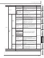
REVISIONS
Print date
Manual number*1
Revision
Jul. 2008
SH(NA)-080781ENG-A
First edition
Jan. 2009
SH(NA)-080781ENG-B
Model Addition
Q00UJ, Q00U, Q01U, Q10UDH, Q10UDEH, Q20UDH, Q20UDEH, FX series
Addition
MANUALS, Section 6.2.7, Appendix 1.4
Correction
GENERIC TERMS AND ABBREVIATIONS IN THIS MANUAL, Section 1.1, Section 1.3.1,
Section 1.3.5, Section 1.3.6, Section 4.2, Section 5.3, Section 5.4, Section 5.7,
Section 6.1.1, Section 6.2.1, Section 6.2.2, Section 6.2.8, Section 7.1, Section 7.2,
Section 7.5, Section 7.5.1, Section 7.6.5, Section 8.1, Section 9.4, Section 9.5,
Section 11.2, Appendix 1.1, Appendix 1.5
Jul. 2009
SH(NA)-080781ENG-C
Model Addition
Q00J, Q00, Q01
Addition
Section 6.4.3, Chapter 7
Correction
MANUALS, GENERIC TERMS AND ABBREVIATIONS IN THIS MANUAL, Section 1.2,
Section 1.3, Section 2.1, Section 4.1, Section 4.2.1, Section 4.2.2, Section 4.2.3,
Section 4.3.1, Section 4.3.2, Section 4.4.1, Section 5.1, Section 5.2, Section 5.3,
Section 5.4, Section 5.6.1, Section 6.1, Section 6.2.1, Section 6.2.3, Section 6.2.4,
Section 6.3, Section 6.3.1, Section 6.4, Section 6.4.4, Section 6.4.10, Section 6.4.11,
Section 6.4.13, Chapter 8, Section 9.1, Section 11.2, Section 11.3, Section 12.2,
Appendix 1
Modification
Section 6.3.4 Section 7.12,
Section 6.4.3 to Section 6.4.12 Section 6.4.4 to Section 6.4.13,
Chapter 7 to Chapter 11 Chapter 8 to Chapter 12
Oct. 2009
SH(NA)-080781ENG-D
Correction
MANUALS, GENERIC TERMS AND ABBREVIATIONS IN THIS MANUAL, Section 1.3.1,
Section 1.3.6, Section 5.1, Section 5.2, Section 5.3, Section 5.4, Section 6.4.2,
Section 6.4.7, Section 12.1, Section 12.2, Appendix 1.2, Appendix 1.6
Jan. 2010
SH(NA)-080781ENG-E
Model Addition
L02, L26-BT
Addition
CONDITIONS OF USE FOR THE PRODUCT, Section 6.2.11
Correction
MANUALS, GENERIC TERMS AND ABBREVIATIONS IN THIS MANUAL, Section 1.3,
Section 2.1, Section 4.1, Section 4.2.3, Section 4.4.1, Section 5.2, Section 5.7,
Section 6.2.2, Section 6.4.2, Section 6.4.3, Section 6.4.7, Section 6.4.13, Section 8.1,
Section 8.2, Section 8.4.7, Section 9.1, Section 12.1, Section 12.2, Appendix 1
Modification
Section 6.2.11 Section 6.2.12
Apr. 2010
SH(NA)-080781ENG-F
Model Addition
Q50UDEH, Q100UDEH, LJ72GF15-T2
Correction
MANUALS, GENERIC TERMS AND ABBREVIATIONS IN THIS MANUAL, Section 1.2,
Section 1.3.1, Section 2.1, Section 5.2, Section 5.3, Section 5.4, Section 5.5, Section 5.7,
Section 8.1, Section 8.2, Section 8.4.3, Section 8.5, Section 11.1, Section 12.2,
Appendix 1.1, Appendix 1.2, Appendix 1.6, Appendix 1.8
Sept. 2010
SH(NA)-080781ENG-G
Addition
Section 5.8
Correction
Section 1.2, Section 1.3.1, Section 4.3.2, Section 4.4.1, Section 5.2, Section 5.3,
Section 5.4, Section 5.7, Section 6.2.1, Section 6.2.2, Section 6.2.10, Section 6.4.2,
Section 6.4.7, Section 8.1, Section 8.2, Section 8.5, Section 9.1, Section 12.1, Section 12.2,
Appendix 1.1, Appendix 1.2, Appendix 1.6
A-3
Print date
Jan. 2011
Manual number*1
SH(NA)-080781ENG-H
Revision
Addition
TERMS, Section 5.5.1, Section 5.5.2, Section 6.2.5, Chapter 7, Chapter 8, Section 11.2.3
Correction
MANUALS, GENERIC TERMS AND ABBREVIATIONS IN THIS MANUAL, Section 1.2,
Section 1.3.1, Section 2.1, Section 4.2.2, Section 4.2.3, Section 5.2, Section 5.3,
Section 5.4, Section 5.5, Section 6.1.1, Section 6.2.1, Section 10.5, Section 11.1,
Section 12.1, Section 12.2, Section 14.2, Appendix 1
Modification
Section 5.5.1 to 5.5.2 Section 5.5.3 to 5.5.4, Section 6.2.2 Section 7.1.4,
Section 6.2.3 Section 6.2.2, Section 6.2.4 Section 8.8,
Section 6.2.5 Section 6.2.3, Section 6.2.6 Section 8.8.7,
Section 6.2.7 Section 8.11, Section 6.2.8 Section 6.2.4,
Section 6.2.10 to 6.2.12 Section 6.2.6 to 6.2.8, Section 6.3 Chapter 7,
Section 6.4 Chapter 8, Section 11.2.2 Section 13.3.1,
Section 11.2.3 Section 13.2.5, Section 11.2.4 Section 13.3.4,
Section 11.2.5 Section 13.2.2, Section 11.2.6 to Section 11.2.7 Section 13.3.3,
Section 11.2.8 Section 13.2.6, Section 11.2.9 to Section 11.2.10 Section 13.2.4,
Section 11.2.11 Section 13.3.5, Section 13.2.7, Chapter 7 to 12 Chapter 9 to 14
Mar. 2011
SH(NA)-080781ENG-I
Addition
Section 5.7.1, Section 10.5.1, Section 10.5.2, Section 10.5.3
Correction
MANUALS, Section 1.3.1, Section 5.4, Section 5.7, Section 6.2.1, Section 6.2.2,
Section 8.2.2, Section 8.9, Section 8.9.2, Section 10.1, Section 10.2, Section 10.4.4,
Section 10.4.6, Section 10.5, Section 11.1, Section 14.2, Appendix 1.1, Appendix 1.6
Jul. 2011
SH(NA)-080781ENG-J
Model Addition
L02-P, L26-PBT
Addition
Section 8.7.2, Section 8.8.7, Appendix 1.2
Correction
MANUALS, GENERIC TERMS AND ABBREVIATIONS IN THIS MANUALS, GENERIC
TERMS AND ABBREVIATIONS IN THIS MANUAL,
Section 1.2, Section 1.3.1, Section 1.3.6, Section 2.1, Section 4.3.2, Section 4.4.1,
Section 5.2, Section 5.3, Section 5.4, Section 5.6.3, Section 5.7.1, Section 6.1,
Section 6.1.2, Section 6.2.1, Section 6.2.6, Section 6.2.7, Section 6.2.8, Section 6.2.9,
Section 8.1, Section 8.2.1, Section 8.5.1, Section 8.5.2, Section 8.6.3, Section 8.7.5,
Section 8.8.4, Section 8.8.7, Section 8.8.8, Section 8.9.3, Section 8.10, Section 8.11,
Section 10.1, Section 10.2, Section 10.4.4, Section 10.5.2, Section 10.5.3,
Section 11.1, Section 12.1, Section 12.3.2, Section 12.4, Section 13.3.7,
Section 13.4.5, Section 14.1, Section 14.2, Appendix 1.6
Modification
Section 8.7.2 to Section 8.7.4 Section 8.7.3 to Section 8.7.5,
Section 8.8.7 Section 8.8.8,
Appendix 1.2 to Appendix 1.8 Appendix 1.3 to Appendix 1.9
Sept. 2011
SH(NA)-080781ENG-K
Correction
Section 1.3.1
Nov. 2011
SH(NA)-080781ENG-L
Correction
MANUALS, Section 1.3.1, Section 4.1, Section 4.2.1, Section 4.2.3, Section 4.3.2,
Section 4.4.1, Section 5.2, Section 5.3, Section 5.4, Section 5.5.3, Section 5.5.4,
Section 5.6.1, Section 5.6.3, Section 5.6.4, Section 6.2.1, Section 6.2.2, Section 6.2.4,
Section 7.1.1, Section 8.3.5, Section 8.7.1, Section 8.7.4, Section 8.7.5, Section 8.8.3,
Section 8.8.5, Section 8.9.2, Section 8.9.3, Section 10.1, Section 10.5.3, Section 10.6,
Section 13.2.4, Section 13.3.1, Section 14.1, Section 14.2, Appendix 1.1, Appendix 1.3,
Appendix 1.7
Modification
Section 1.3.5 to Section 1.3.6 Section 1.3.2 to Section 1.3.3,
Section 13.2 to Section 13.4 Section 13.4 to Section 13.3,
Appendix 1.3 Appendix 1.2, Appendix 1.7 Appendix 1.3
Deletion
Section 1.3.2, Section 1.3.3, Section 1.3.4, Section 13.1, Appendix 1.2, Appendix 1.4,
Appendix 1.5, Appendix 1.6, Appendix 1.8, Appendix 1.9
A-4
Print date
Jan. 2012
Manual number*1
SH(NA)-080781ENG-M
Revision
Model Addition
FX3GC
Correction
Section 1.3.1, Section 5.5.4, Section 11.1, Section 14.2
May 2012
SH(NA)-080781ENG-N
Model Addition
Q02PH, Q06PH, Q12PH, Q12PRH, Q25PH, Q25PRH
Addition
Section 5.5.4
Correction
Section 1.3.1, Section 2.1, Section 3.1, Section 4.2.3, Section 4.4.1, Section 5.2,
Section 5.5.3, Section 5.6.1, Section 5.6.3, Section 5.6.4, Section 5.7.1, Section 8.3.3,
Section 8.8.7, Section 10.5.3, Section 14.2,
Appendix 1.1, Appendix 1.2
Modification
Section 5.5.4 Section 5.5.5
Sept. 2012
SH(NA)-080781ENG-O
Addition
Section 5.7, Section 10.4.6
Correction
Section 1.3.1, Section 6.1.2, Section 6.2.8, Section 7.1.4, Section 10.1, Section 10.2,
Section 10.5.2, Section 14.1, Section 14.2
Modification
Section 5.7 to Section 5.8 Section 5.8 to Section 5.9,
Section 10.4.6 to Section 10.4.7 Section 10.4.7 to Section 10.4.8
Feb. 2013
SH(NA)-080781ENG-P
Model Addition
Q03UDV, Q04UDV, Q06UDV, Q13UDV, Q26UDV, L02S, L06, L26
Addition
Section 5.5.6, Section 10.4.7, Section 12.6
Correction
GENERIC TERMS AND ABBREVIATIONS IN THIS MANUAL, Section 1.3.1, Section 2.1,
Section 3.1, Section 4.3.2, Section 4.4.1, Section 6.2.1, Section 10.4.2, Section 12.1.1,
Section 13.2.7, Section 14.2, Appendix 1.1, Appendix 1.3
Modification
Section 10.4.7 to Section 10.4.8 Section 10.4.8 to Section 10.4.9
Section 12.1 Section 12.1.1 to Section 12.1.2
May 2013
SH(NA)-080781ENG-Q
Model Addition
L02S-P, L06-P, L26-P, FX3S
Correction
GENERIC TERMS AND ABBREVIATIONS IN THIS MANUAL, Section 2.1, Section 5.5.2,
Section 7.1.1, Section 8.2.2, Section 8.4.2, Section 8.4.3, Section 10.5.3, Section 12.6,
Section 14.2
Sept. 2013
SH(NA)-080781ENG-R
Addition
Section 8.7.5
Correction
Section 1.3.3, Section 5.5.6, Section 8.6.1, Section 14.2
Modification
Section 8.7.3 to Section 8.7.5 Section 8.7.2 to Section 8.7.4
Deletion
Section 8.7.2
Dec. 2013
SH(NA)-080781ENG-S
Correction
Section 4.1, Section 4.4.1, Section 5.6.4, Section 8.8.5, Section 10.5.3, Section 14.1,
Section 14.2
A-5
Print date
Manual number*1
Revision
Mar. 2014
SH(NA)-080781ENG-T
Correction
Section 4.4.1, Section 5.5.3, Section 5.6.4, Section 10.5.3
Jun. 2014
SH(NA)-080781ENG-U
Correction
Section 5.2, Section 5.5.1, Section 10.2, Section 14.1, Section 14.2
Sept. 2014
SH(NA)-080781ENG-V
Correction
Section 13.3.5, Appendix 1
Dec. 2014
SH(NA)-080781ENG-W
Correction
Section 10.1, Section 10.2
Mar. 2015
SH(NA)-080781ENG-X
Correction
Section 10.5, Section 12.1.2, Section 13.3.1, Section 14.2
*1 :
The manual number is written at the bottom left of the back cover.
Japanese Manual Version SH-080732-AG
This manual confers no industrial property rights or any rights of any other kind, nor does it confer any patent licenses.
Mitsubishi Electric Corporation cannot be held responsible for any problems involving industrial property rights which may occur
as a result of using the contents noted in this manual.
2008 MITSUBISHI ELECTRIC CORPORATION
A-6
INTRODUCTION
Thank you for purchasing the Mitsubishi integrated FA software, MELSOFT series.
Before using the product, thoroughly read this manual to develop full familiarity with the functions and performance
to ensure correct use.
CONTENTS
SAFETY PRECAUTIONS . . . . . . . . . . . . . . . . . . . . . . . . . . . . . . . . . . . . . . . . . . . . . . . . . . . . . . A - 1
CONDITIONS OF USE FOR THE PRODUCT. . . . . . . . . . . . . . . . . . . . . . . . . . . . . . . . . . . . . . . A - 2
REVISIONS . . . . . . . . . . . . . . . . . . . . . . . . . . . . . . . . . . . . . . . . . . . . . . . . . . . . . . . . . . . . . . . . . A - 3
INTRODUCTION . . . . . . . . . . . . . . . . . . . . . . . . . . . . . . . . . . . . . . . . . . . . . . . . . . . . . . . . . . . . . A - 7
CONTENTS . . . . . . . . . . . . . . . . . . . . . . . . . . . . . . . . . . . . . . . . . . . . . . . . . . . . . . . . . . . . . . . . . A - 7
MANUALS . . . . . . . . . . . . . . . . . . . . . . . . . . . . . . . . . . . . . . . . . . . . . . . . . . . . . . . . . . . . . . . . . A - 13
GENERIC TERMS AND ABBREVIATIONS IN THIS MANUAL . . . . . . . . . . . . . . . . . . . . . . . . . A - 22
TERMS. . . . . . . . . . . . . . . . . . . . . . . . . . . . . . . . . . . . . . . . . . . . . . . . . . . . . . . . . . . . . . . . . . . . A - 22
1
2
OVERVIEW
1.1
What is Structured Project?
1-2
1.2
Features of Structured Project
1-2
1.3
List of Functions
1-5
List of functions for editing in Structured Text . . . . . . . . . . . . . . . . . . . . . . . . . . . . . . . . . . . . . . . 1 - 8
1.3.3
List of functions for editing in Structured Ladder/FBD . . . . . . . . . . . . . . . . . . . . . . . . . . . . . . . . . 1 - 9
Overview of Screen Configuration
2-2
PROGRAMMING PROCEDURE
3.1
4
List of functions common to Simple project and Structured project . . . . . . . . . . . . . . . . . . . . . . . 1 - 5
1.3.2
SCREEN CONFIGURATION
2.1
3
1.3.1
Creating Programs
3-2
PROGRAM CONFIGURATIONS
4.1
Program Configurations of Structured Project
4-2
4.2
Creating Program Files and Tasks
4-3
4.2.1
4.3
Procedure for creating program files and tasks . . . . . . . . . . . . . . . . . . . . . . . . . . . . . . . . . . . . . . 4 - 3
4.2.2
Registering program blocks to tasks . . . . . . . . . . . . . . . . . . . . . . . . . . . . . . . . . . . . . . . . . . . . . . 4 - 4
4.2.3
Setting executing conditions. . . . . . . . . . . . . . . . . . . . . . . . . . . . . . . . . . . . . . . . . . . . . . . . . . . . . 4 - 7
Creating POUs
4.3.1
4 - 10
Procedure for creating POUs . . . . . . . . . . . . . . . . . . . . . . . . . . . . . . . . . . . . . . . . . . . . . . . . . . . 4 - 10
A-7
4.3.2
4.4
Using POUs
4.4.1
5
Setting properties of functions and function blocks . . . . . . . . . . . . . . . . . . . . . . . . . . . . . . . . . . 4 - 11
4 - 14
Using functions and function blocks. . . . . . . . . . . . . . . . . . . . . . . . . . . . . . . . . . . . . . . . . . . . . . 4 - 15
SETTING LABELS
5.1
The Type of Label Setting Editor
5-2
5.2
Setting Global Labels
5-3
5.3
Setting Local Labels for Program Blocks
5-8
5.4
Setting Labels for Functions and Function Blocks
5 - 10
5.5
Common Operations for Setting Labels
5 - 12
5.5.1
5.6
Classes . . . . . . . . . . . . . . . . . . . . . . . . . . . . . . . . . . . . . . . . . . . . . . . . . . . . . . . . . . . . . . . . . . . 5 - 12
5.5.2
Data types . . . . . . . . . . . . . . . . . . . . . . . . . . . . . . . . . . . . . . . . . . . . . . . . . . . . . . . . . . . . . . . . . 5 - 13
5.5.3
Selecting data types. . . . . . . . . . . . . . . . . . . . . . . . . . . . . . . . . . . . . . . . . . . . . . . . . . . . . . . . . . 5 - 14
5.5.4
Label comments. . . . . . . . . . . . . . . . . . . . . . . . . . . . . . . . . . . . . . . . . . . . . . . . . . . . . . . . . . . . . 5 - 17
5.5.5
Editing rows . . . . . . . . . . . . . . . . . . . . . . . . . . . . . . . . . . . . . . . . . . . . . . . . . . . . . . . . . . . . . . . . 5 - 17
5.5.6
Deleting unused labels. . . . . . . . . . . . . . . . . . . . . . . . . . . . . . . . . . . . . . . . . . . . . . . . . . . . . . . . 5 - 21
Setting Structure Labels
5.6.1
5 - 23
Setting structures . . . . . . . . . . . . . . . . . . . . . . . . . . . . . . . . . . . . . . . . . . . . . . . . . . . . . . . . . . . . 5 - 23
5.6.2
Defining data type of label as structure . . . . . . . . . . . . . . . . . . . . . . . . . . . . . . . . . . . . . . . . . . . 5 - 24
5.6.3
Assigning devices to structure labels . . . . . . . . . . . . . . . . . . . . . . . . . . . . . . . . . . . . . . . . . . . . . 5 - 25
5.6.4
Assigning devices to structure array labels . . . . . . . . . . . . . . . . . . . . . . . . . . . . . . . . . . . . . . . . 5 - 27
5.7
Checking Duplications of Devices Assigned to Global Labels
5 - 30
5.8
Setting Ranges for Devices Assigned Automatically
5 - 31
5.8.1
5.9
6
Considerations of automatically assigned devices. . . . . . . . . . . . . . . . . . . . . . . . . . . . . . . . . . . 5 - 32
Writing/Reading Data to/from CSV Files
5 - 34
COMMON OPERATIONS OF PROGRAM EDITORS
6.1
6.2
A-8
Types of Program Editor
6-2
6.1.1
Available programming languages. . . . . . . . . . . . . . . . . . . . . . . . . . . . . . . . . . . . . . . . . . . . . . . . 6 - 3
6.1.2
Available comment types . . . . . . . . . . . . . . . . . . . . . . . . . . . . . . . . . . . . . . . . . . . . . . . . . . . . . . . 6 - 4
Common Operations of Program Editors
6-5
6.2.1
Using POUs (Element Selection window) . . . . . . . . . . . . . . . . . . . . . . . . . . . . . . . . . . . . . . . . . . 6 - 5
6.2.2
Using labels in the program . . . . . . . . . . . . . . . . . . . . . . . . . . . . . . . . . . . . . . . . . . . . . . . . . . . . . 6 - 8
6.2.3
Undo and redo . . . . . . . . . . . . . . . . . . . . . . . . . . . . . . . . . . . . . . . . . . . . . . . . . . . . . . . . . . . . . . 6 - 11
6.2.4
Changing display size of editing screen. . . . . . . . . . . . . . . . . . . . . . . . . . . . . . . . . . . . . . . . . . . 6 - 11
6.2.5
Splitting editing screen . . . . . . . . . . . . . . . . . . . . . . . . . . . . . . . . . . . . . . . . . . . . . . . . . . . . . . . . 6 - 12
6.2.6
Opening local label setting screen of program editor being edited . . . . . . . . . . . . . . . . . . . . . . 6 - 13
6.2.7
Displaying compilation result in list format . . . . . . . . . . . . . . . . . . . . . . . . . . . . . . . . . . . . . . . . . 6 - 13
6.2.8
Setting display content of tooltip . . . . . . . . . . . . . . . . . . . . . . . . . . . . . . . . . . . . . . . . . . . . . . . . 6 - 14
6.2.9
Opening label setting and program screens for selected POU . . . . . . . . . . . . . . . . . . . . . . . . . 6 - 15
7
EDITING ST PROGRAMS
7.1
8
ST Editor
7-2
7.1.1
Writing ST programs. . . . . . . . . . . . . . . . . . . . . . . . . . . . . . . . . . . . . . . . . . . . . . . . . . . . . . . . . . . 7 - 3
7.1.2
Automatic indention . . . . . . . . . . . . . . . . . . . . . . . . . . . . . . . . . . . . . . . . . . . . . . . . . . . . . . . . . . . 7 - 3
7.1.3
Setting tab length . . . . . . . . . . . . . . . . . . . . . . . . . . . . . . . . . . . . . . . . . . . . . . . . . . . . . . . . . . . . . 7 - 4
7.1.4
Using templates . . . . . . . . . . . . . . . . . . . . . . . . . . . . . . . . . . . . . . . . . . . . . . . . . . . . . . . . . . . . . . 7 - 5
EDITING STRUCTURED LADDER/FBD PROGRAMS
8.1
Creating Ladder/FBD Programs
8.1.1
8.2
8.3
8.4
8.5
8.6
8.7
8.8
8-2
Selecting editing modes . . . . . . . . . . . . . . . . . . . . . . . . . . . . . . . . . . . . . . . . . . . . . . . . . . . . . . . . 8 - 3
Editing in Select Mode
8-4
8.2.1
Entering elements. . . . . . . . . . . . . . . . . . . . . . . . . . . . . . . . . . . . . . . . . . . . . . . . . . . . . . . . . . . . . 8 - 4
8.2.2
Entering instructions . . . . . . . . . . . . . . . . . . . . . . . . . . . . . . . . . . . . . . . . . . . . . . . . . . . . . . . . . . . 8 - 5
Drawing Lines
8-7
8.3.1
Connecting lines automatically when entering elements . . . . . . . . . . . . . . . . . . . . . . . . . . . . . . . 8 - 7
8.3.2
Connecting elements with lines . . . . . . . . . . . . . . . . . . . . . . . . . . . . . . . . . . . . . . . . . . . . . . . . . . 8 - 8
8.3.3
Connecting lines automatically . . . . . . . . . . . . . . . . . . . . . . . . . . . . . . . . . . . . . . . . . . . . . . . . . . . 8 - 8
8.3.4
Overwriting input/output variable with lines . . . . . . . . . . . . . . . . . . . . . . . . . . . . . . . . . . . . . . . . . 8 - 9
8.3.5
Rearranging lines automatically . . . . . . . . . . . . . . . . . . . . . . . . . . . . . . . . . . . . . . . . . . . . . . . . . . 8 - 9
8.3.6
Inserting and deleting rows and columns . . . . . . . . . . . . . . . . . . . . . . . . . . . . . . . . . . . . . . . . . . 8 - 10
Operating Elements
8 - 11
8.4.1
Moving elements . . . . . . . . . . . . . . . . . . . . . . . . . . . . . . . . . . . . . . . . . . . . . . . . . . . . . . . . . . . . 8 - 11
8.4.2
Moving elements with lines connected . . . . . . . . . . . . . . . . . . . . . . . . . . . . . . . . . . . . . . . . . . . . 8 - 11
8.4.3
Copying elements. . . . . . . . . . . . . . . . . . . . . . . . . . . . . . . . . . . . . . . . . . . . . . . . . . . . . . . . . . . . 8 - 13
Changing Type of Contact and Coil
8 - 15
8.5.1
Setting the type of contact and coil. . . . . . . . . . . . . . . . . . . . . . . . . . . . . . . . . . . . . . . . . . . . . . . 8 - 15
8.5.2
Changing contact and coil in predetermined order. . . . . . . . . . . . . . . . . . . . . . . . . . . . . . . . . . . 8 - 17
Operating Functions and Function Blocks
8 - 18
8.6.1
Adding variables automatically when entering functions and function blocks . . . . . . . . . . . . . . 8 - 18
8.6.2
Editing variable names and instance names . . . . . . . . . . . . . . . . . . . . . . . . . . . . . . . . . . . . . . . 8 - 19
8.6.3
Changing the number of arguments for functions and function blocks. . . . . . . . . . . . . . . . . . . . 8 - 20
Changing Display Format of Variables
8 - 21
8.7.1
Displaying variable names in multiple lines . . . . . . . . . . . . . . . . . . . . . . . . . . . . . . . . . . . . . . . . 8 - 21
8.7.2
Displaying instance names in multiple lines . . . . . . . . . . . . . . . . . . . . . . . . . . . . . . . . . . . . . . . . 8 - 22
8.7.3
Specifying the number of displaying characters for variable names . . . . . . . . . . . . . . . . . . . . . 8 - 22
8.7.4
Changing display format of variable . . . . . . . . . . . . . . . . . . . . . . . . . . . . . . . . . . . . . . . . . . . . . . 8 - 23
8.7.5
Displaying additional label items . . . . . . . . . . . . . . . . . . . . . . . . . . . . . . . . . . . . . . . . . . . . . . . . 8 - 26
Editing Ladder Blocks
8.8.1
8 - 27
Inserting ladder blocks . . . . . . . . . . . . . . . . . . . . . . . . . . . . . . . . . . . . . . . . . . . . . . . . . . . . . . . . 8 - 27
8.8.2
Deleting ladder blocks . . . . . . . . . . . . . . . . . . . . . . . . . . . . . . . . . . . . . . . . . . . . . . . . . . . . . . . . 8 - 27
8.8.3
Cutting, copying, pasting, and moving ladder blocks . . . . . . . . . . . . . . . . . . . . . . . . . . . . . . . . . 8 - 28
8.8.4
Editing ladder block headers . . . . . . . . . . . . . . . . . . . . . . . . . . . . . . . . . . . . . . . . . . . . . . . . . . . 8 - 29
8.8.5
Editing listed ladder blocks . . . . . . . . . . . . . . . . . . . . . . . . . . . . . . . . . . . . . . . . . . . . . . . . . . . . . 8 - 30
8.8.6
Setting ladder block labels/titles . . . . . . . . . . . . . . . . . . . . . . . . . . . . . . . . . . . . . . . . . . . . . . . . . 8 - 32
A-9
8.9
8.10
8.8.7
Switching to display/hide left power rail . . . . . . . . . . . . . . . . . . . . . . . . . . . . . . . . . . . . . . . . . . . 8 - 32
8.8.8
Displaying grid . . . . . . . . . . . . . . . . . . . . . . . . . . . . . . . . . . . . . . . . . . . . . . . . . . . . . . . . . . . . . . 8 - 33
Editing Comments
8.9.1
Editing comments. . . . . . . . . . . . . . . . . . . . . . . . . . . . . . . . . . . . . . . . . . . . . . . . . . . . . . . . . . . . 8 - 34
8.9.2
Changing the size of comment entry field . . . . . . . . . . . . . . . . . . . . . . . . . . . . . . . . . . . . . . . . . 8 - 34
8.9.3
Moving comments . . . . . . . . . . . . . . . . . . . . . . . . . . . . . . . . . . . . . . . . . . . . . . . . . . . . . . . . . . . 8 - 35
Editing in Guided Mode
8.10.1
8.11
9
8 - 34
8 - 36
Overwrite mode and insert mode . . . . . . . . . . . . . . . . . . . . . . . . . . . . . . . . . . . . . . . . . . . . . . . . 8 - 36
8.10.2
Entering elements . . . . . . . . . . . . . . . . . . . . . . . . . . . . . . . . . . . . . . . . . . . . . . . . . . . . . . . . . . . 8 - 37
8.10.3
Entering instructions. . . . . . . . . . . . . . . . . . . . . . . . . . . . . . . . . . . . . . . . . . . . . . . . . . . . . . . . . . 8 - 37
8.10.4
Connecting elements with lines . . . . . . . . . . . . . . . . . . . . . . . . . . . . . . . . . . . . . . . . . . . . . . . . . 8 - 37
8.10.5
Drawing lines . . . . . . . . . . . . . . . . . . . . . . . . . . . . . . . . . . . . . . . . . . . . . . . . . . . . . . . . . . . . . . . 8 - 38
8.10.6
Wrapping lines . . . . . . . . . . . . . . . . . . . . . . . . . . . . . . . . . . . . . . . . . . . . . . . . . . . . . . . . . . . . . . 8 - 38
8.10.7
Setting Guided mode as the default editing mode . . . . . . . . . . . . . . . . . . . . . . . . . . . . . . . . . . . 8 - 39
8.10.8
Entering variable names after contacts and coils. . . . . . . . . . . . . . . . . . . . . . . . . . . . . . . . . . . . 8 - 39
8.10.9
Inserting comment entry fields to ladder blocks to be added . . . . . . . . . . . . . . . . . . . . . . . . . . . 8 - 40
Checking Wrapping Position for Printing
8 - 41
SEARCHING FOR SPECIFIC POSITION
9.1
9.2
Searching for Specific Position in ST Program
9.1.1
Jumping to specified line . . . . . . . . . . . . . . . . . . . . . . . . . . . . . . . . . . . . . . . . . . . . . . . . . . . . . . . 9 - 2
9.1.2
Using bookmarks . . . . . . . . . . . . . . . . . . . . . . . . . . . . . . . . . . . . . . . . . . . . . . . . . . . . . . . . . . . . . 9 - 2
Searching for Specific Position in Structured Ladder/FBD Program
9.2.1
10
9-2
9-4
Jumping to specified ladder block number. . . . . . . . . . . . . . . . . . . . . . . . . . . . . . . . . . . . . . . . . . 9 - 4
CONVERTING/COMPILING PROGRAMS
10.1
Converting/Compiling Created Programs
10 - 2
10.2
Compiling All Programs
10 - 4
10.3
Executing Online Program Change Simultaneously with Conversion/Compilation
10 - 6
10.4
Changing Operating Conditions of Compilation
10 - 6
10.4.1
10.5
A - 10
Changing the number of errors and warnings that stop compilation . . . . . . . . . . . . . . . . . . . . . 10 - 6
10.4.2
Hiding warning messages . . . . . . . . . . . . . . . . . . . . . . . . . . . . . . . . . . . . . . . . . . . . . . . . . . . . . 10 - 7
10.4.3
Using same name for global label and local label . . . . . . . . . . . . . . . . . . . . . . . . . . . . . . . . . . . 10 - 8
10.4.4
Using same lower case label name as device . . . . . . . . . . . . . . . . . . . . . . . . . . . . . . . . . . . . . . 10 - 8
10.4.5
Connecting PLS, PLF, or ALT outputs directly to other inputs with lines . . . . . . . . . . . . . . . . . . 10 - 9
10.4.6
Using VAR_OUTPUT for an argument of function block . . . . . . . . . . . . . . . . . . . . . . . . . . . . . 10 - 10
10.4.7
Assigning temporary arguments for arguments when calling function block . . . . . . . . . . . . . . 10 - 10
10.4.8
Assigning common devices to outputs of function with EN/ENO . . . . . . . . . . . . . . . . . . . . . . . 10 - 11
10.4.9
Retaining bit type outputs of functions . . . . . . . . . . . . . . . . . . . . . . . . . . . . . . . . . . . . . . . . . . . 10 - 14
Compilation
10 - 15
10.5.1
Compilation target data when compiling all programs . . . . . . . . . . . . . . . . . . . . . . . . . . . . . . . 10 - 15
10.5.2
Assigning devices . . . . . . . . . . . . . . . . . . . . . . . . . . . . . . . . . . . . . . . . . . . . . . . . . . . . . . . . . . 10 - 16
10.5.3
Considerations of Compilation . . . . . . . . . . . . . . . . . . . . . . . . . . . . . . . . . . . . . . . . . . . . . . . . . 10 - 19
10.6
Checking for Errors and Warnings
10.6.1
11
11 - 2
Starting and Stopping Monitoring Programs
12 - 2
12.1.1
Starting monitoring programs . . . . . . . . . . . . . . . . . . . . . . . . . . . . . . . . . . . . . . . . . . . . . . . . . . . 12 - 2
12.1.2
Stopping monitoring programs . . . . . . . . . . . . . . . . . . . . . . . . . . . . . . . . . . . . . . . . . . . . . . . . . . 12 - 3
12.2
Starting and Stopping Monitoring Function Blocks
12 - 4
12.3
Changing Operating Conditions of Monitoring
12 - 5
12.3.1
Changing current value display format (decimal/hexadecimal) of word type variable . . . . . . . . 12 - 5
12.3.2
Setting the number of displaying characters for character strings . . . . . . . . . . . . . . . . . . . . . . . 12 - 6
12.4
Monitoring Programs on ST Editor
12 - 7
12.5
Monitoring Programs in Structured Ladder/FBD Editor
12 - 9
12.6
Setting Monitoring Conditions
12 - 11
USING USER LIBRARIES
13.1
Procedure for Using User Library
13 - 2
13.2
Creating User Library
13 - 3
13.3
14
Writing/Reading Data to/from Programmable Controller CPU
MONITORING
12.1
13
Correcting errors and warnings . . . . . . . . . . . . . . . . . . . . . . . . . . . . . . . . . . . . . . . . . . . . . . . . 10 - 24
WRITING/READING DATA TO/FROM PROGRAMMABLE CONTROLLER CPU
11.1
12
10 - 23
13.2.1
Creating user libraries . . . . . . . . . . . . . . . . . . . . . . . . . . . . . . . . . . . . . . . . . . . . . . . . . . . . . . . . 13 - 3
13.2.2
Changing library name . . . . . . . . . . . . . . . . . . . . . . . . . . . . . . . . . . . . . . . . . . . . . . . . . . . . . . . . 13 - 4
13.2.3
Creating data . . . . . . . . . . . . . . . . . . . . . . . . . . . . . . . . . . . . . . . . . . . . . . . . . . . . . . . . . . . . . . . 13 - 4
13.2.4
Saving library file . . . . . . . . . . . . . . . . . . . . . . . . . . . . . . . . . . . . . . . . . . . . . . . . . . . . . . . . . . . . 13 - 5
13.2.5
Deleting user library from project . . . . . . . . . . . . . . . . . . . . . . . . . . . . . . . . . . . . . . . . . . . . . . . . 13 - 7
13.2.6
Setting password to user library . . . . . . . . . . . . . . . . . . . . . . . . . . . . . . . . . . . . . . . . . . . . . . . . . 13 - 8
13.2.7
Set help file to library . . . . . . . . . . . . . . . . . . . . . . . . . . . . . . . . . . . . . . . . . . . . . . . . . . . . . . . . . 13 - 9
Using User Library
13 - 10
13.3.1
Installing user library data to project. . . . . . . . . . . . . . . . . . . . . . . . . . . . . . . . . . . . . . . . . . . . . 13 - 10
13.3.2
Creating programs using user library . . . . . . . . . . . . . . . . . . . . . . . . . . . . . . . . . . . . . . . . . . . . 13 - 12
13.3.3
Editing user library . . . . . . . . . . . . . . . . . . . . . . . . . . . . . . . . . . . . . . . . . . . . . . . . . . . . . . . . . . 13 - 13
13.3.4
Updating user library . . . . . . . . . . . . . . . . . . . . . . . . . . . . . . . . . . . . . . . . . . . . . . . . . . . . . . . . 13 - 15
13.3.5
Displaying user library help . . . . . . . . . . . . . . . . . . . . . . . . . . . . . . . . . . . . . . . . . . . . . . . . . . . 13 - 16
SETTING OPTIONS
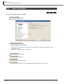
14.1
Basic Operations
14 - 2
14.2
Option Setting List
14 - 3
A - 11
APPENDIX
Appendix 1
INDEX
A - 12
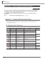
List of Toolbars and Shortcut Keys
App - 2
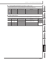
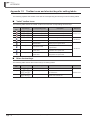
Appendix 1.1
Common toolbars and shortcut keys . . . . . . . . . . . . . . . . . . . . . . . . . . . . . . . . . . . . App - 2
Appendix 1.2
Toolbar icons and shortcut keys for setting labels . . . . . . . . . . . . . . . . . . . . . . . . . . App - 4
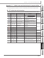
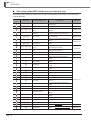
Appendix 1.3
Toolbar icons and shortcut keys for program editors . . . . . . . . . . . . . . . . . . . . . . . . App - 5
■
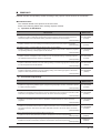
MANUALS
Related manuals are separately issued according to the purpose of their functions in GX Works2.
● Related manuals
The manuals related to this product are shown below.
Refer to the following tables when ordering required manuals.
1)
Operation of GX Works2
Manual name
Manual number
(Model code)
GX Works2 Version 1 Operating Manual (Common)
Explains the system configuration of GX Works2 and the functions common to Simple project and
Structured project such as parameter setting, operation method for the online function.
(Sold separately)
SH-080779ENG
(13JU63)
GX Works2 Version 1 Operating Manual (Simple Project)
Explains methods for such as creating and monitoring programs in Simple project of GX Works2.
(Sold separately)
SH-080780ENG
(13JU64)
GX Works2 Version 1 Operating Manual (Simple Project, Function Block)
Explains methods for such as creating function blocks, pasting function blocks to sequence programs,
and operating FB library in Simple project of GX Works2.
(Sold separately)
SH-080984ENG
(13JU72)
GX Works2 Version 1 Operating Manual (Intelligent Function Module)
Explains methods of intelligent function module for such as parameter setting, monitoring programs,
and predefined protocol support function in GX Works2.
(Sold separately)
SH-080921ENG
(13JU69)
GX Works2 Beginner's Manual (Simple Project)
Explains fundamental methods for such as creating, editing, and monitoring programs in Simple project
for users inexperienced with GX Works2
(Sold separately)
SH-080787ENG
(13JZ22)
GX Works2 Beginner's Manual (Structured Project)
Explains fundamental methods for such as creating, editing, and monitoring programs in Structured
project for users inexperienced with GX Works2.
(Sold separately)
SH-080788ENG
(13JZ23)
2)
Structured Programming
Manual name
Manual number
(Model code)
MELSEC-Q/L/F Structured Programming Manual (Fundamentals)
Explains the programming methods, types of programming languages, and other information required
to create structured programs.
(Sold separately)
SH-080782ENG
(13JW06)
MELSEC-Q/L Structured Programming Manual (Common Instructions)
Explains the specifications and functions of common instructions such as sequence instructions, basic
instructions, and application instructions that can be used in structured programs.
(Sold separately)
SH-080783ENG
(13JW07)
MELSEC-Q/L Structured Programming Manual (Application Functions)
Explains the specifications and functions of application functions that can be used in structured
programs.
(Sold separately)
SH-080784ENG
(13JW08)
MELSEC-Q/L Structured Programming Manual (Special Instructions)
Explains the specifications and functions of special instructions such as module dedicated instruction,
PID control instruction, and built-in I/O function dedicated instruction, that can be used in structured
programs.
(Sold separately)
SH-080785ENG
(13JW09)
FXCPU Structured Programming Manual [Device & Common]
Explains the devices and parameters provided in GX Works2 for structured programming.
(Sold separately)
JY997D26001
(09R925)
FXCPU Structured Programming Manual [Basic & Applied Instruction]
Explains the sequence instructions provided in GX Works2 for structured programming.
(Sold separately)
JY997D34701
(09R926)
A - 13
Manual name
Manual number
(Model code)
FXCPU Structured Programming Manual [Application Functions]
Explains the application functions provided in GX Works2 for structured programming.
(Sold separately)
JY997D34801
(09R927)
3)
Operation of iQ Works
Manual name
Manual number
(Model code)
Let's start iQ Works Version 2
Explains fundamental methods for such as managing the system using MELSOFT Navigator and using
system labels for users inexperienced with GX Works2.
(Sold separately)
SH-081261ENG
(13JZ79)
The Operating Manuals are included on the CD-ROM of the software package in a PDF file format. Manuals in printed
form are sold separately for single purchase. Order a manual by quoting the manual number (model code) listed in the
table above.
A - 14
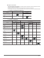
● Purpose of this manual
This manual explains the operations for creating sequence programs in Structured project using the
functions supported by GX Works2.
Manuals for reference are listed in the following table according to their purpose.
For information such as the content and number of each manual, refer to the list of 'Related manuals'.
1)
Installation of GX Works2 and USB driver
Purpose
GX Works2 Installation Instructions
GX Works2 Version 1
Operating Manual
Common
Learning the operating
environment and installation
method
Details
Learning a USB driver installation
method
2)
Details
Operation of GX Works2
GX Works2 Beginner's
Manual
Purpose
Simple
Project
Structured
Project
Learning all functions of GX
Works2
Learning the basic operations
and operating procedures when
creating a structured project for
the first time
Learning the operations of
available functions regardless of
project type.
Learning the functions and
operation methods for
programming
Learning the operations and
operating procedures when
creating function blocks (FB) in
Simple project.
Learning data setting methods for
intelligent function module
Simple Project
Common
Function
Block
Structured
Project
Intelligent
Function
Module
Outline
Learning the project types and
available languages in GX
Works2
Learning the basic operations
and operating procedures when
creating a simple project for the
first time
GX Works2 Version 1
Operating Manual
Outline
Details
Details
Details
Outline
Details
Details
Details
Details
A - 15
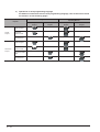
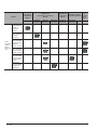
3)
Operations in each programming language
For details of instructions used in each programming language, refer to the section 4 and
the section 5 on the following pages.
GX Works2 Beginner's Manual
Purpose
Ladder Diagram
Simple
Project
Sequential
Function Chart
Simple
Project
Structured
Project
Sequential
Function Chart
Structured Ladder
/FBD
Structured Text
*1 :
MELSAP3 and FX series SFC only
A - 16
Simple
Project
Structured
Project
Outline
Details
*1
Outline
Details
Outline
Structured Text
Ladder Diagram
Structured
Project
GX Works2 Version 1
Operating Manual
Details
Outline
Details
*1
Outline
Details
Outline
Details
Outline
Details
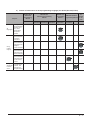
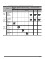
4)
Details of instructions in each programming language (for QCPU (Q mode)/LCPU)
Purpose
MELSEC-Q/L/F
Structured
Programming
Manual
MELSEC-Q/L
Structured Programming
Manual
Fundamentals
Common
Special
Application
Instructions Instructions Functions
Manual
for
MELSEC-Q/L
MELSEC-Q/L/QnA
module
Programming
Programming Manual
to be
Manual
used
Common
Instruction
Learning details
of programmable
controller CPU
All
error codes,
languages
special relays,
and special
registers
Details
Learning the
types and details
of common
instructions
Details
Using
Ladder
Diagram
PID Control
Instructions
SFC
-
Learning the
types and details
of instructions for
intelligent
function modules
Details
Learning the
types and details
of instructions for
network modules
Details
Learning the
types and details
of instructions for
the PID control
function
Learning details
Using
of specifications,
Sequential
functions, and
Function
instructions of
Chart
SFC (MELSAP3)
Details
Details
A - 17
Purpose
Learning the
fundamentals for
creating a
structured
program
Learning the
types and details
of common
instructions
Learning the
types and details
Using
of instructions for
Structured intelligent
Ladder/
function modules
FBD or
Structured Learning the
types and details
Text
of instructions for
network modules
Learning the
types and details
of instructions for
the PID control
function
Learning the
types and details
of application
instructions
A - 18
MELSEC-Q/L/F
Structured
Programming
Manual
MELSEC-Q/L
Structured Programming
Manual
Fundamentals
Common
Special
Application
Instructions Instructions Functions
Manual
for
MELSEC-Q/L
MELSEC-Q/L/QnA
module
Programming
Programming Manual
to be
Manual
used
Common
Instruction
PID Control
Instructions
SFC
-
Details
Details
Outline
Details
Outline
Details
Details
Outline
Details
5)
Details of instructions in each programming language (for FXCPU)
Purpose
MELSEC-Q/L/F
Structured
FXCPU Structured Programming Manual
Programming
Manual
FX0,FX0S,
FX0N,FX1,
FX2,FX2C
FX1S,FX1N,
FX2N,FX1NC,
FX2NC
FX3S,
FX3G,FX3U,
FX3GC,FX3UC
Using
Ladder
Diagram
Learning the
types and details
of basic/
application
instructions,
descriptions of
devices and
parameters
Details
Details
Details
Using
Sequential
Function
Chart
Learning details
of specifications,
functions, and
instructions of
SFC
Details
Details
Details
Fundamentals
Learning the
fundamentals for
creating a
structured
program
Using
Structured
Ladder/
FBD or
Structured
Text
Learning the
descriptions of
devices,
parameters, and
error codes
Learning the
types and details
of sequence
instructions
Learning the
types and details
of application
instructions
Device &
Common
Instructions
Basic &
Applied
Instruction
FXCPU Programming Manual
Application
Functions
Details
Details
Details
Details
A - 19
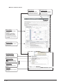
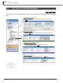
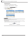
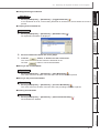
● How to read this manual
Screen display
Describes the screen display
procedure.
Follow the
and select
[(menu)] to open the screen.
*Screen display may differ
depending on the CPU type.
In that case, typical example is
described.
Display contents
Describes the display contents
on the screen.
Operating procedure
Describes the operating
procedure of the function.
Reference location
leads to the reference
location and reference manual.
Screen button
Describes the buttons on the
screen.
Section title
Clarifies the section of currently
open page.
A - 20
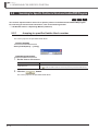
Supported CPU
Chapter heading
Supported programmable
controller CPUs are shown in
icons under the section title.
Index on the right of the page
number clarifies the chapter of
currently open page.
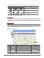
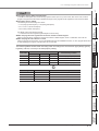
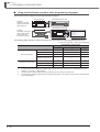
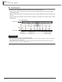
The following table explains the CPU module icons that indicate the function availability.
Icon
QCPU (Q mode)
LCPU
FXCPU
Q CPU
L CPU
FX
Q CPU
-
-
Q CPU
L CPU
FX
Description
Normal icons indicate that the corresponding function
is available.
Icons with * (asterisk) symbol indicate that the
corresponding function is available with restrictions
such as CPU types.
*1
Icons with symbol × indicate that the corresponding
function is not available.
This manual also uses the following columns:
This indicates notes for requiring attention or useful functions relating to the information given on the
same page.
Restrictions
This indicates restrictions relating to the information given on the same page.
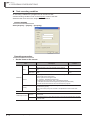
● Symbols used in this manual
The following shows the symbols used in this manual with descriptions and examples.
1
2
3
4
5
6
No.
Symbol
[
]
(Underline)
<<
>>
""
[Project]
Screen name
Q Parameter Setting screen
Tab name on a screen
<<PLC System>>
Item name on a screen
"Timer Limit Setting"
Button on a screen
-
Menu name on a menu bar
Example
Toolbar icon
Description
Keyboard key
button
A - 21
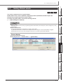
■
GENERIC TERMS AND ABBREVIATIONS IN THIS MANUAL
The following are the generic terms/abbreviations of such as software packages and programmable
controller CPUs used in this manual.
Generic term and abbreviation
Description
GX Works2
Generic product name for SWnDNC-GXW2-E
(n: version)
Existing application
-
GX Developer
Product name for SWnD5C-GPPW-E, SWnD5C-GPPW-EA, SWnD5C-GPPW-EV, and
SWnD5C-GPPW-EVA
(n: version)
GX IEC Developer
Product name for SWnD5C-MEDOC3
(n: version)
MELSOFT Navigator
Product name for the integrated development environment included in SWnDNC-IQWK
(MELSOFT iQ Works)
(n: version)
iQ Works
Abbreviation for MELSOFT iQ Works
Personal computer
Generic term for personal computer on which Windows® operates
Basic model QCPU
Generic term for Q00J, Q00, and Q01
High Performance model QCPU
Generic term for Q02, Q02H, Q06H, Q12H, and Q25H
Process CPU
Generic term for Q02PH, Q06PH, Q12PH, and Q25PH
Redundant CPU
Generic term for Q12PRH and Q25PRH
Universal model QCPU
Generic term for Q00UJ, Q00U, Q01U, Q02U, Q03UD, Q03UDE, Q03UDV, Q04UDH,
Q04UDEH, Q04UDV, Q06UDH, Q06UDEH, Q06UDV, Q10UDH, Q10UDEH, Q13UDH,
Q13UDEH, Q13UDV, Q20UDH, Q20UDEH, Q26UDH, Q26UDEH, Q26UDV, Q50UDEH,
and Q100UDEH
High-speed Universal model
QCPU
Generic term for Q03UDV, Q04UDV, Q06UDV, Q13UDV, and Q26UDV
QCPU (Q mode)
Generic term for Basic model QCPU, High Performance model QCPU, Process CPU,
Redundant CPU, and Universal model QCPU
LCPU
Generic term for L02S, L02S-P, L02, L02-P, L06, L06-P, L26, L26-P, L26-BT, and L26PBT
FXCPU
Generic term for FX0S, FX0, FX0N, FX1, FX1S, FX1N, FX1NC, FXU, FX2C, FX2N, FX2NC,
FX3S, FX3G, FX3GC, FX3U, and FX3UC
FXGP (WIN)
Abbreviation for SW0PC-FXGP/WIN-E
MELSAP3
Abbreviation for the SFC function in MELSAP3 display format
MELSAP-L
Generic term for the SFC function in MELSAP-L (instruction format) and MELSAP-L (start
conditions format)
SFC
Generic term for MELSAP3, MELSAP-L, and FX series SFC
■
TERMS
The following are the terms used in this manual.
Term
A - 22
Description
Simple project
Generic term for projects created by using Ladder Diagram/Sequential Function Chart/
Structured Text
Structured project
Generic term for projects created by using Ladder Diagram/Sequential Function Chart/
Structured Text/Structured Ladder/FBD
Common instruction
Generic term for sequence instructions, basic instructions, application instructions, data
link instructions, multiple CPU dedicated instructions, and multiple CPU high-speed
transmission dedicated instructions
Special instruction
Generic term for module dedicated instructions, PID control instructions, socket
communication function instructions, built-in I/O function instructions, and data logging
function instructions
List format
An input format to input mnemonic language in a ladder program
OVERVIEW
2
SCREEN
CONFIGURATION
1
OVERVIEW
1
This manual explains specific operating procedures using Structured project.
For the full product features and functions of GX Works2, refer to the following manual.
GX Works2 Version 1 Operating Manual (Common)
PROGRAMMING
PROCEDURE
3
Features of Structured Project
1-2
1.3
List of Functions
1-5
5
SETTING LABELS
1.2
6
COMMON
OPERATIONS OF
PROGRAM EDITORS
1-2
7
EDITING ST
PROGRAMS
What is Structured Project?
8
EDITING STRUCTURED
LADDER/FBD
PROGRAMS
1.1
PROGRAM
CONFIGURATIONS
4
1-1
GX Works2
1 OVERVIEW
1.1
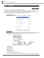
What is Structured Project?
In Structured project, programs can be created using the structured programming.
By segmenting the control functions and creating components from commonly used parts of
programs, this type of programming (structured programming) is easy to understand visually, and
created components are highly reusable to other programs.
1.2
Features of Structured Project
This section explains the features of Structured project.
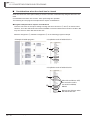
■
Various programming languages are available
Various programming languages are available for structured programs. Users can combine these
languages by selecting the most appropriate programming language for each purpose to create
programs.
Language
Description
Ladder Diagram (LD)*1
A graphic language using ladders composed of contacts and coils.
Can be operated in a similar way to existing GX Developer operation.
Structured Text (ST)
A high-level structured text language with grammatical structure similar to C language.
Sequential Function Chart
(SFC)*1
A graphic language in which executing orders and executing conditions of programs are
defined.
Structured Ladder
A graphic language using ladders composed of contacts and coils, which can be inserted
flexibly.
Function Block Diagram
(FBD)
*1 :
■
A graphic language using ladders by connecting functions and/or function blocks with lines.
Not supported by FXCPU.
Common program editors for each programmable controller CPU
The program editors of Structured project can be used for any type of programmable controller CPU
supported by GX Works2. Users can select the desired programming languages regardless of the
target programmable controller CPU.
For details of the programmable controller CPUs supported by GX Works2, refer to the following
manual.
GX Works2 Version 1 Operating Manual (Common)
1-2
1.2 Features of Structured Project
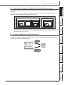
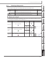
■
1
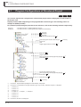
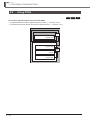
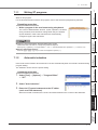
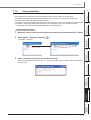
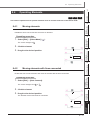
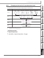
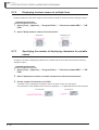
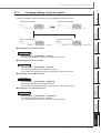
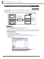
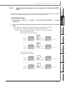
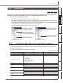
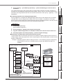
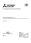
Creating large programs efficiently with structured programming
OVERVIEW
In Structured project, programs can be easily structured by managing program components in a
hierarchy.*1
Programs that are easy to maintain and highly reusable can be created efficiently by structuring
programs. This is suitable for developing large programs.
2
Project
Program file 2
Task 1
Task 2
SCREEN
CONFIGURATION
Program file 1
Task 3
■
A program is created in units of POUs (abbreviation for Program Organization Units) such as program blocks (PRGs),
functions (FUNs), and function blocks (FBs). Function blocks can be nested in a hierarchy. Created programs are
registered to the tasks of program files.
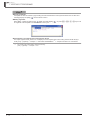
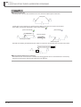
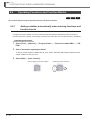
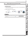
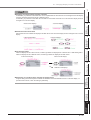
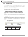
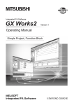
Assets of programs are utilized as libraries
4
In Structured project, sequence program components can be saved as libraries which can be utilized
as assets of programs in multiple projects.
Register to
libraries
PROGRAM
CONFIGURATIONS
*1 :
PROGRAMMING
PROCEDURE
3
5
GX Works2
SETTING LABELS
Library
Utilize programs
COMMON
OPERATIONS OF
PROGRAM EDITORS
6
EDITING ST
PROGRAMS
7
EDITING STRUCTURED
LADDER/FBD
PROGRAMS
8
1-3
GX Works2
1 OVERVIEW
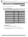
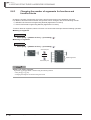
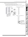
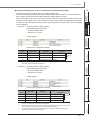
■
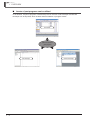
Assets of past programs can be utilized
In GX Works2, sequence programs created with previous versions of GX Developer and GX IEC
Developer can be imported, which enables efficient utilization of program assets.
GX Works2
Utilize the assets of
past programs
GX Developer
1-4
GX IEC Developer
1.3 List of Functions
1.3
1
List of Functions
2
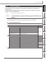
… GX Works2 Version 1 Operating Manual (Common)
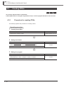
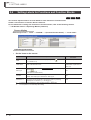
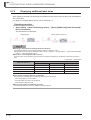
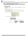
1.3.1
List of functions common to Simple project and Structured
project
SCREEN
CONFIGURATION
(Common)
OVERVIEW
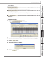
This section shows the list of functions to create programs using Structured Ladder/FBD and
Structured Text.
For all the functions of GX Works2 and the functions with "(Common)" indicated in the reference
column, refer to the following manual.
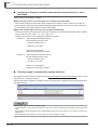
List of common functions
The following tables show functions that are available regardless of the type of editing or setting target.
Project (common function)
Object
New
Reference
-
Add data to the project.
Rename
Rename the selected data.
Delete
Delete the selected data.
Copy
Copy the selected data.
Paste
Paste the copied data.
Set as Default Connection
Specify data in selected connection destination as a connection
destination for regular use.
Property
Display the selected data properties.
Library
(Common)
Create a new library.
Section 13.2.1
Install
Import a created library to the project.
Section 13.3.1
Deinstall
Delete the library from the project.
Section 13.2.5
Reload
Update the library imported to the project.
Section 13.3.4
Rename
Rename the library.
Section 13.2.2
Open
Enable editing of the library.
Close
Disable editing of the library.
Change Password
Set a password for the library.
Name and save the project.
Save
Save the library file.
Help
Display help information of the library.
6
Section 13.2.6
Section 13.2.4
7
Section 13.3.3
Section 13.3.5
EDITING ST
PROGRAMS
Save As
5
COMMON
OPERATIONS OF
PROGRAM EDITORS
Create
4
PROGRAM
CONFIGURATIONS
■
SETTING LABELS
This section explains the functions common to Simple project and Structured project.
PROGRAMMING
PROCEDURE
3
EDITING STRUCTURED
LADDER/FBD
PROGRAMS
8
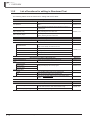
1.3.1 List of functions common to Simple project and Structured project
1-5
GX Works2
1 OVERVIEW
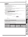
Edit (common function)
Undo
Restore the previous processing status.
Redo
Restore the processing deleted with [Undo].
Cut
Cut the selected data.
Copy
Copy the selected data.
Paste
Paste the cut or copied data at the cursor position.
Compile (common function)
Build
Convert/compile a program being edited.
Online Program Change
Write sequence programs to a programmable controller CPU
after the conversion/compilation.
Rebuild All
Convert/compile all programs in the project.
View (common function)
Docking Window
Section 6.2.3
-
Reference
Section 10.1
(Common)
Section 10.2
Reference
-
Navigation
Display/hide the Navigation window.
Element Selection
Display/hide the Element Selection window.
Select a part such as function block and function on the window
for utilizing it to a program.
Section 6.2.1
Output
Display/hide the Output window.
The conversion (compilation) result is displayed.
Section 10.6
Online (common function)
Read from PLC
Read data from the programmable controller CPU.
Write to PLC
Write data to the programmable controller CPU.
Monitor
(Common)
Reference
Section 11.1
-
Start Monitoring (All Windows)
Start monitoring the programs of all open windows.
Stop Monitoring (All Windows)
Stop monitoring the programs of all open windows.
Start Monitoring
Start monitoring the program of the open window.
Section 12.1.1
Stop Monitoring
Stop monitoring the program of the open window.
Section 12.1.2
Change Value Format (Decimal)
Display the current device value in decimal in program
monitoring.
Change Value Format (Hexadecimal)
Display the current device value in hexadecimal in program
monitoring.
Change Instance (Function Block)
Select an instance of the function block to be monitored.
Tool (common function)
1-6
Reference
(Common)
Section 12.3.1
Section 12.2
Reference
Check Device Duplication of Global Label
Check duplications of devices assigned to global labels, and
display the result.
Section 5.7
Device/Label Automatic-Assign Setting
Set device range to be automatically assigned to a label.
Section 5.8
Options
Set various options.
Chapter 14
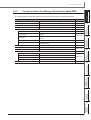
1.3.1 List of functions common to Simple project and Structured project
1.3 List of Functions
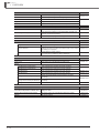
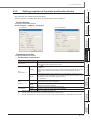
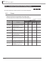
■
1
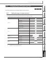
List of functions for setting labels
Delete the selected data.
Select All
Select all items.
New Declaration (Before)
Add a row above the cursor position.
New Declaration (After)
Add a row below the cursor position.
Delete Row
Delete the row at the cursor position.
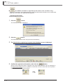
Read from CSV File
Read label settings from the CSV file.
Write to CSV File
Write label settings to the CSV file.
Section 5.5.5
Section 5.9
-
Reservation to Register System Label
Reserve the selected global label for registration as a
system label.
Reservation to Release System Label
Reserve the selected global label for deregistration of
system label.
Import System Label
Import system label information and apply it to global
labels.
Reflect to System Label Database
Apply the registration-reserved/deregistration-reserved
global labels to the system label data base.
Confirm Update of System Label Database
Apply system label information changed in another project
to global labels.
Execute Verification Synchronous with
System Label
Resolve a mismatch when system label information
contains it.
Sort
3
Section 5.2
4
-
Class
Label Name
Device
Sort the labels in ascending/descending order with the
selected item.
Section 5.5.5
Extract and display unused labels.
Extracted unused labels can be deleted in batch.
Section 5.5.6
Address
Comment
6
EDITING ST
PROGRAMS
7
8
EDITING STRUCTURED
LADDER/FBD
PROGRAMS
Unused label list
COMMON
OPERATIONS OF
PROGRAM EDITORS
Remark
SETTING LABELS
5
Data Type
Constant
2
PROGRAM
CONFIGURATIONS
System Label
-
SCREEN
CONFIGURATION
Delete
Reference
PROGRAMMING
PROCEDURE
Edit (function for label setting)
OVERVIEW
The following table shows the functions for setting and editing labels.
1.3.1 List of functions common to Simple project and Structured project
1-7
GX Works2
1 OVERVIEW
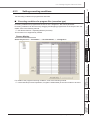
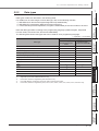
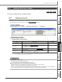
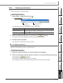
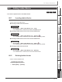
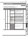
1.3.2
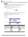
List of functions for editing in Structured Text
The following tables show the functions for editing with the ST editor.
Edit (function for editing in Structured Text)
Delete
Delete the selected data.
List Operands
Display the screen for inserting a label by selecting an existing
label.
Display Template
Insert a template corresponds to the instruction, function, or
control syntax.
Mark Template (Left)
Set an argument of the template in the selected status from the
left by selecting the menu each time.
Mark Template (Right)
Set an argument of the template in the selected status from the
right by selecting the menu each time.
Find/Replace (function for editing in Structured Text)
Jump
Jump to the specified line.
Bookmark
Reference
Section 6.2.2
Section 7.1.4
Reference
Section 9.1.1
-
Set a bookmark at the cursor line. The bookmark is deleted
when one is already set at the cursor line.
Toggle Bookmark
Bookmark List
Jump to the specified bookmark from the bookmark list.
Next Bookmark
Display the next bookmark position.
Previous Bookmark
Display the previous bookmark position.
Delete All Bookmarks
Cancels all bookmarks.
View (function for editing in Structured Text)
Display Compile Result
Display the compilation result in a list format.
Zoom
Section 9.1.2
Reference
Section 6.2.7
-
Set Zoom Factor
Increase Zoom
Change the display size of the program.
Section 6.2.4
Decrease Zoom
Zoom Header/Body
-
Header
Open the label setting editor in the selected POU.
Body
Open the program editor in the selected POU.
Open the Local Label Setting screen for the program being
edited.
Open Header
Online (function for editing in Structured Text)
Monitor
1-8
Section 6.2.9
Section 6.2.6
Reference
-
Start Monitoring
Start monitoring with the split window format that displays
monitor data of numeric value and character strings.
Start Monitor (bit type only)
Start monitoring only bit type devices/labels.
1.3.2 List of functions for editing in Structured Text
Section 12.4
1.3 List of Functions
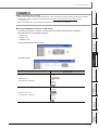
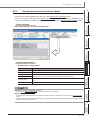
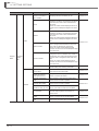
Edit (function for editing in Structured Ladder/FBD)
Reference
Delete
Delete the selected data.
Select Mode
Change to the contact and coil input mode.
Section 8.4.1
Interconnect Mode
Change to the line drawing mode.
Section 8.3.2
Auto Connect
Specify and connect the start and end points to draw a line.
Section 8.3.3
Guided Editing
Change to the keyboard input mode.
Section 8.10
Overwrite Mode
Overwrite the element entered in Guided editing at the cursor
position.
Insert Mode
Insert the element entered in Guided editing at the cursor
position.
Line Mode
Auto Comment
Recalculate Line
-
Section 8.10.1
3
Change the input format to draw lines in Guided editing.
Section 8.10.4
Add a comment entry field at the start of the ladder block added
in Guided editing.
Section 8.10.9
Arrange a line automatically to redraw it.
Section 8.3.5
Insert Row
Insert a row in a ladder program being edited.
Insert Column
Insert a column in a ladder program being edited.
New Ladder Block List
Section 8.3.6
-
Top
Insert a new ladder block at the start of all ladder blocks.
Before
Insert a new ladder block in front of a ladder block being edited.
After
Insert a new ladder block after a ladder block being edited.
Bottom
Insert a new ladder block at the end of all ladder blocks.
Section 8.2.2
5
SETTING LABELS
Open the Input Instruction screen.
Section 8.8.1
4
COMMON
OPERATIONS OF
PROGRAM EDITORS
6
EDITING ST
PROGRAMS
7
8
EDITING STRUCTURED
LADDER/FBD
PROGRAMS
Input Instruction
2
PROGRAMMING
PROCEDURE
Guided Mode
-
SCREEN
CONFIGURATION
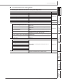
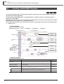
The following tables show the functions for editing with the Structured Ladder/FBD editor.
OVERVIEW
1
List of functions for editing in Structured Ladder/FBD
PROGRAM
CONFIGURATIONS
1.3.3
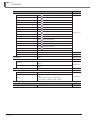
1.3.3 List of functions for editing in Structured Ladder/FBD
1-9
GX Works2
1 OVERVIEW
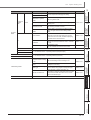
Edit (function for editing in Structured Ladder/FBD)
Ladder Symbol
Reference
-
Open Contact
Insert
at the cursor position.
Close Contact
Insert
at the cursor position.
Coil
Insert
at the cursor position.
Jump
Insert
at the cursor position.
Return
Insert
at the cursor position.
Open Branch
Insert
at the cursor position.
Close Branch
Insert
at the cursor position.
Input Label
Insert
at the cursor position.
Output Label
Insert
at the cursor position.
Horizontal Line Segment
Insert
at the cursor position.
Vertical Line Segment
Insert
at the cursor position.
Rising Pulse
Insert
at the cursor position.
Falling Pulse
Insert
at the cursor position.
Rising Pulse Close
Insert
at the cursor position.
Falling Pulse Close
Insert
at the cursor position.
Section 8.2.1
Comment
Insert a comment entry field at the cursor position.
Ladder Block Label
Display the Ladder Block screen.
Section 8.8.4
Left Power Rail
Display/hide the left power rail.
Section 8.8.7
Display the screen for inserting a label by selecting an existing
label.
Section 6.2.2
List Operands
Number of Pins
-
Increment
Increase the number of arguments of functions and function
blocks.
Delete
Decrease the number of arguments of functions and function
blocks.
Ladder Block List
Display a list of ladder blocks in a program.
Signal Configuration
Configure
Toggle
Section 8.6.3
Section 8.8.5
-
Set the type of a contact and a coil.
Change the contact and coil type per execution in the following
order.
Section 8.5
• Contact: Open Contact Close Contact
• Coil: Normal Negation Set Reset
Find/Replace (function for editing in Structured Ladder/FBD)
Jump
1 - 10
Jump to the specified ladder block number.
1.3.3 List of functions for editing in Structured Ladder/FBD
Reference
Section 9.2.1
1.3 List of Functions
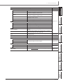
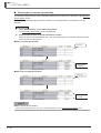
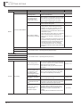
View (function for editing in Structured Ladder/FBD)
Display variables by its entered format.
Device
Display devices/addresses in device format. Devices assigned
to labels are displayed in device format.
Address
Display devices/addresses in address format. Devices assigned
to labels are displayed in address format.
Comment
Display devices/addresses in device comment. Labels are
displayed in label comment.
Change Label-Device-Address Mode
Switch the display format in order (label, device, address).
Change Label-Comment Mode
Switch the display between label and comment.
OVERVIEW
-
Label
2
Section 8.7.4
Device
Display devices assigned to labels.
Address
Display addresses assigned to labels.
Label Comment
Display label comments assigned to labels.
Device Comment
Display device comments correspond to devices or addresses.
Batch-change all labels on the program editors to the device
display.
Cancel All Device Display
Cancel the device display on the program editors, and display
data in the format at the time of data entry.
Grid
Show a grid on the screen being edited to display the start/end
positions of a line.
Print Wrap Position
Display Compile Result
Section 8.8.8
4
Display the wrapping position for printing.
Section 8.11
Display the compilation result in a list format.
Section 6.2.7
PROGRAM
CONFIGURATIONS
All Device Display
3
PROGRAMMING
PROCEDURE
Add Label Display Items
-
Set Zoom Factor
Change the display size of the program.
Section 6.2.4
Decrease Zoom
Zoom Header/Body
Header
Open the label setting editor in the selected POU.
Body
Open the program editor in the selected POU.
Open the Local Label Setting screen for the program being
edited.
Section 6.2.9
Section 6.2.6
COMMON
OPERATIONS OF
PROGRAM EDITORS
6
EDITING ST
PROGRAMS
7
8
EDITING STRUCTURED
LADDER/FBD
PROGRAMS
Open Header
5
-
SETTING LABELS
Zoom
Increase Zoom
1
SCREEN
CONFIGURATION
View Mode
Reference
1.3.3 List of functions for editing in Structured Ladder/FBD
1 - 11
GX Works2
1 OVERVIEW
MEMO
1 - 12
SETTING LABELS
Overview of Screen Configuration
COMMON
OPERATIONS OF
PROGRAM EDITORS
2.1
EDITING ST
PROGRAMS
2-2
PROGRAM
CONFIGURATIONS
PROGRAMMING
PROCEDURE
2
EDITING STRUCTURED
LADDER/FBD
PROGRAMS
OVERVIEW
SCREEN
CONFIGURATION
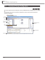
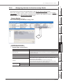
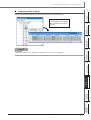
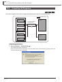
This chapter explains the screen configuration of GX Works2.
SCREEN
CONFIGURATION
1
2
3
4
5
6
7
8
2-1
GX Works2
2 SCREEN CONFIGURATION
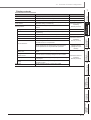
2.1
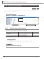
Overview of Screen Configuration
Q CPU L CPU
FX
This section explains the main frame (basic screen) of GX Works2 that is displayed when it is started
up.
The following screen shows a main frame configuration on which a work window and docked
windows are displayed.
Screen display
Title bar
Menu bar
Toolbar
Navigation
window
Element Selection
window
Work
window
Docked window
Status bar
2-2
2.1 Overview of Screen Configuration
1
Display contents
Display tool buttons for executing each function.
Work window
A main screen used for operations such as programming,
parameter setting, and monitoring.
Docking window
A sub screen to support operations performed on a work
window.
Appendix 1
GX Works2 Version 1
Operating
Manual (Common)
Navigation
Display contents of a project in tree format.
Section 4.1
Element Selection
Display a list of functions (such as function blocks) used for
programming.
Section 6.2.1
Output
Display compilation and check results (errors and warnings).
Section 10.6
Cross Reference
Display cross reference results.
Device List
Display the device usage list.
Display assignments of refresh devices and link devices
specified for the CC-Link parameter.
Device Reference
Display assignments of refresh devices and input/output
devices specified for the AnyWireASLINK parameter.
Watch 1 to 4
A screen used for monitoring and changing current device
values.
Intelligent Function Module
Monitor 1 to 10
A screen used for monitoring intelligent function modules.
Find/Replace
A screen used for searching and replacing character strings
in the project.
Debug
A screen used for setting the debug which uses the
simulation function.
GX Works2 Version 1
Operating
Manual (Common)
GX Works2 Version 1
Operating Manual
(Intelligent Function
Module)
GX Works2 Version 1
Operating
Manual (Common)
2
3
4
5
SETTING LABELS
Display information about a project being edited.
COMMON
OPERATIONS OF
PROGRAM EDITORS
6
EDITING ST
PROGRAMS
7
8
EDITING STRUCTURED
LADDER/FBD
PROGRAMS
Status bar
OVERVIEW
Display menu options for executing each function.
Toolbar
-
SCREEN
CONFIGURATION
Menu bar
Reference
PROGRAMMING
PROCEDURE
Description
Display a project name.
PROGRAM
CONFIGURATIONS
Name
Title bar
2-3
GX Works2
2 SCREEN CONFIGURATION
MEMO
2-4
SETTING LABELS
Creating Programs
COMMON
OPERATIONS OF
PROGRAM EDITORS
3.1
EDITING ST
PROGRAMS
3-2
PROGRAM
CONFIGURATIONS
PROGRAMMING
PROCEDURE
3
EDITING STRUCTURED
LADDER/FBD
PROGRAMS
OVERVIEW
PROGRAMMING
PROCEDURE
This chapter explains how to create programs in Structured project.
SCREEN
CONFIGURATION
1
2
3
4
5
6
7
8
3-1
GX Works2
3 PROGRAMMING PROCEDURE
3.1
Creating Programs
Q CPU L CPU
FX
This section explains the general operating steps from the creation of a program in Structured project
to the execution of the created program on the programmable controller CPU.
Operating procedure
1.
Creating a new project
Procedure
Reference
Start up GX Works2.
Create a new Structured project.
To reuse an existing Structured project, open that Structured project.
2.
Setting parameters
Procedure
Reference
Set parameters.
GX Works2 Version 1
Operating Manual (Common)
Check parameters.
3.
GX Works2 Version 1
Operating Manual (Common)
Configuring programs
Procedure
Reference
Create program files.
Create tasks.
Chapter 4
Create POUs.
Register POUs (program blocks) to the tasks.
4.
Setting labels
Procedure
Reference
Define global labels.
Chapter 5
Define local labels.
(To the next page)
3-2
3.1 Creating Programs
1
Editing programs
Procedure
3
PROGRAMMING
PROCEDURE
Reference
Chapter 10
Connecting a personal computer to the programmable controller CPU
Procedure
Connect a personal computer to the programmable controller CPU.
Set the connection destination.
4
Reference
GX Works2 Version 1
Operating Manual (Common)
PROGRAM
CONFIGURATIONS
Compile a program or compile all programs.
8.
SCREEN
CONFIGURATION
Compiling programs
Procedure
7.
2
Chapter 6
Chapter 7
Chapter 8
Edit programs of each POU.
6.
Reference
5
Writing data to the programmable controller CPU
Procedure
Write parameters to the programmable controller CPU.
Write sequence programs to the programmable controller CPU.
SETTING LABELS
5.
OVERVIEW
(From the previous page)
Reference
Chapter 11
9.
COMMON
OPERATIONS OF
PROGRAM EDITORS
6
Confirming the operation
Procedure
Reference
Monitor the execution status of sequence programs.
Chapter 12
7
Save the project.
Exit GX Works2.
Reference
GX Works2 Version 1
Operating Manual (Common)
8
EDITING STRUCTURED
LADDER/FBD
PROGRAMS
Procedure
EDITING ST
PROGRAMS
10.Ending the project
3-3
GX Works2
3 PROGRAMMING PROCEDURE
MEMO
3-4
PROGRAM
CONFIGURATIONS
2
SCREEN
CONFIGURATION
4
OVERVIEW
1
In Structured project, sequence programs are configured by using tasks and POUs.
This chapter explains the program configurations of Structured project.
PROGRAMMING
PROCEDURE
3
Program Configurations of Structured Project
4-2
4.2
Creating Program Files and Tasks
4-3
4.3
Creating POUs
4 - 10
4.4
Using POUs
4 - 14
5
SETTING LABELS
4.1
PROGRAM
CONFIGURATIONS
4
COMMON
OPERATIONS OF
PROGRAM EDITORS
6
EDITING ST
PROGRAMS
7
EDITING STRUCTURED
LADDER/FBD
PROGRAMS
8
4-1
GX Works2
4 PROGRAM CONFIGURATIONS
4.1
Program Configurations of Structured Project
Q CPU L CPU
FX
This section explains the configurations of Structured project that are displayed in a tree format on
the Project view.
Display contents differ depending on the programmable controller type. The following shows an
example of QCPU (Q mode).
For (Common) and (Intelligent) indicated as the reference, refer to the following manuals respectively:
(Common)
… GX Works2 Version 1 Operating Manual (Common)
(Intelligent)
… GX Works2 Version 1 Operating Manual (Intelligent Function Module)
*1
(Common)
(Intelligent)
(Common)
Define labels shared among POUs.
*3
*2
Define the program execution order and type.
Program file
Task
*4
Register program blocks to the task.
Define POUs.
(Common)
*5
*6
Function block (FB)/Function (FUN)
Write a program in the desired programming language.
*8
Define labels.
*6
Program configuration
Program block
Write a program in the desired programming language.
*7
Define labels.
Define structures.
*9
(Common)
*10
*1 :
For FXCPU, "Special Module (Intelligent Function Module)" is displayed.
*2 :
For FXCPU, no classification for program execution type. Only one item, "Execution Program", is displayed.
*3 :
Section 5.2
*4 :
Section 4.2
*5 :
Section 4.3
*6 :
Chapter 6, Chapter 7, Chapter 8
*7 :
Section 5.3
*8 :
Section 5.4
*9 :
Section 5.6
*10 : For FXCPU, this item is not displayed.
4-2
4.2 Creating Program Files and Tasks
FX
This section explains how to register program blocks executed on the programmable controller CPU,
and setting the executing conditions of programs using program files and tasks.
For details of program files and tasks, refer to the following manual.
MELSEC-Q/L/F Structured Programming Manual (Fundamentals)
4.2.1
Procedure for creating program files and tasks
3
PROGRAMMING
PROCEDURE
The following explains the procedure for creating a program file and task.
Operating procedure
1.
Creating a program file and task
Procedure
Reference
4
Create a program file.
Select Project view "Program Setting" "(program setting)", and perform the following
operation.
• Select [Project] [Object] [New].
Create a task.
Select Project view "Program Setting" "(program setting)" "(program file)", and
perform the following operation.
2
SCREEN
CONFIGURATION
Q CPU L CPU
OVERVIEW
1
Creating Program Files and Tasks
GX Works2 Version 1
Operating Manual (Common)
• Select [Project] [Object] [New].
PROGRAM
CONFIGURATIONS
4.2
Procedure
Reference
SETTING LABELS
5
Display the Task Setting screen.
Select Project view "Program Setting" "(program setting)" "(program file)" "(task)".
GX Works2 Version 1
Operating Manual (Common)
6
Registering program blocks to the task
Set program blocks to be registered to the task.
3.
COMMON
OPERATIONS OF
PROGRAM EDITORS
2.
Section 4.2.2
Setting the executing condition
Procedure
7
Reference
Set the executing condition (execution type) of the program file.
Section 4.2.3
EDITING ST
PROGRAMS
Set the executing condition on the Property screen of the task.
Select the task and perform the following operation.
• Select [Project] [Object] [Property].
EDITING STRUCTURED
LADDER/FBD
PROGRAMS
8
4.2.1 Procedure for creating program files and tasks
4-3
GX Works2
4 PROGRAM CONFIGURATIONS
4.2.2
Registering program blocks to tasks
Register program blocks to a task and specify the executing order. Only the program blocks that are
registered to the task are compiled. (Chapter 10)
Operating procedure
1.
Select Project view "Program Setting" "(program setting)" "(program file)"
"(task)".
2.
Right-click and select [Open Task Setting] from the shortcut menu.
The Task Setting screen is displayed.
3.
Set the items on the screen.
Item
Maximum
number of
characters
Description
Program Name
Enter a program block name.
Click
to set a program block name on the Program Selection
screen.
32
Comment
Enter comments for the program block.
A new line can be inserted into a cell by pressing the +
keys.
1024
● Program blocks that can be registered
A single program block can be registered to any one of tasks for only once. Only the program blocks that are not
registered to any of the tasks are displayed on the Program Selection screen.
● Executing order of program blocks registered to a task
Structured Ladder/FBD or ST programs are executed in the order they are registered to a task.
SFC program is executed in the order of block number, regardless of the order they are registered to the task.
4-4
4.2.2 Registering program blocks to tasks
4.2 Creating Program Files and Tasks
● Maximum number of tasks that can be created in a single program file and the maximum
number of program blocks that can be registered to a single task
Maximum number of tasks that can be
created in a single program file
Ladder Diagram
1
1
Sequential Function Chart
Structured Text
3
320*1
124
Structured Ladder/FBD
*1 :
Maximum number of program blocks
that can be registered to a single task
320
For Basic model QCPU/Q00UJ/Q00U/Q01U/Q02U/L02, the maximum number of SFC blocks is 128.
● Program block that can be registered to a single task
: Applicable, ×: Not applicable
Programming language
Program block that can be registered to a single task
Ladder
SFC
ST
Structured Ladder/FBD
Ladder Diagram
×
×
×
Sequential Function Chart
×
×
×
Structured Text
×
×
Structured Ladder/FBD
×
×
PROGRAMMING
PROCEDURE
Programming language of
program block registered to the
first task
2
SCREEN
CONFIGURATION
A maximum number of tasks that can be created in a single project is 124. A maximum number of
program blocks that can be registered to tasks is 800.
However, the number of tasks that can be registered to a program file, the number of program blocks
that can be registered to a task, and the type of program block that can be registered to a single task
differ according to the selected programming language.
OVERVIEW
1
Registering tasks
4
PROGRAM
CONFIGURATIONS
■
SETTING LABELS
5
COMMON
OPERATIONS OF
PROGRAM EDITORS
6
EDITING ST
PROGRAMS
7
EDITING STRUCTURED
LADDER/FBD
PROGRAMS
8
4.2.2 Registering program blocks to tasks
4-5
GX Works2
4 PROGRAM CONFIGURATIONS
■
Setting program names on the program selection screen
Set a program block on the Task Setting screen using the Program Selection screen.
Screen display
On the Task Setting screen, click
next to the "Program Name" entry field.
Operating procedure
1.
Select the reference source of the program block from the "Libraries" field.
Libraries
Description
<ALL>
Browse all program blocks defined in the project and libraries.
<Project>
Browse program blocks defined in the project.
(Library name)
Browse program blocks defined in the specified library.
2.
Select a program block from the "Programs" field.
3.
Click the
button when the setting is completed.
The selected program block is displayed on the Task Setting screen.
4-6
4.2.2 Registering program blocks to tasks
4.2 Creating Program Files and Tasks
1
Setting executing conditions
■
OVERVIEW
Set executing conditions for program files and tasks.
Executing conditions for program files (execution type)
Executing conditions for program files are set on the <<Program>> tab of PLC parameter.
Executing conditions can also be set by dragging and dropping program files on the Project view. For
details, refer to the following manual.
GX Works2 Version 1 Operating Manual (Common)
This function is not supported by FXCPU.
2
SCREEN
CONFIGURATION
4.2.3
3
Screen display
PROGRAMMING
PROCEDURE
Select Project view "Parameter" "PLC Parameter" <<Program>>.
PROGRAM
CONFIGURATIONS
4
SETTING LABELS
5
For details of the program executing conditions, refer to the following manual.
User's Manual (Function Explanation, Program Fundamentals) of the CPU module to be used
COMMON
OPERATIONS OF
PROGRAM EDITORS
6
EDITING ST
PROGRAMS
7
EDITING STRUCTURED
LADDER/FBD
PROGRAMS
8
4.2.3 Setting executing conditions
4-7
GX Works2
4 PROGRAM CONFIGURATIONS
■
Task executing condition
An executing condition for a program file can be set to a task.
A task executing condition is set on the Property screen of the task.
Select the task to be set on the Project view in advance.
Screen display
Select [Project] [Object] [Property].
Operating procedure
•
Set the items on the screen.
Item
Event
Description
TRUE
Execute the task in every scan.
Always
FALSE
Execute the task in the cycle specified in the "Interval"
field.
Interval
Device or
label name
Execute the task when the specified device or label is
TRUE.
Event
Interval
Set the cycle time to execute the task in a constant cycle.
(Enter FALSE in the "Event" field.)
Set the cycle time in time type format
(Ex.: T#100ms, T#24d20h31m23s647ms).
For details of time type format, refer to the following manual.
MELSEC-Q/L/F Structured Programming Manual (Fundamentals)
Do not set shorter time than the scan time of sequence program.
Priority
Set the task execution priority in the range from 0 to 31. Tasks with smaller values
are executed by priority.
Tasks of the same priority are executed in the alphabetical order of task data
names.
Attributes
Title
Enter a title of the task.
Selected
The outputs and the current values of timers in the task are reset when the task is
not executed.
Cleared
The outputs and the current values of timers in the task are retained when the task
is not executed.
Timer/Output Control
4-8
Task executing
condition
4.2.3 Setting executing conditions
4.2 Creating Program Files and Tasks
The following tables show the task executing order according to the set execution type (always (priority:
high/low), interval, or event) in the task property setting.
Task attributes
Task executing condition
Event
Interval
Priority
Task 1
TRUE
0
31
Always (priority: low)
Task 2
M0
0
31
Event
Task 3
FALSE
T#100ms
31
Interval
Task 4
TRUE
0
30
Always (priority: high)
3
4
PROGRAM
CONFIGURATIONS
Task name
SCREEN
CONFIGURATION
For details, refer to the following manual.
FXCPU Structured Programming Manual [Device & Common]
● When the program block registered to the task is created in Ladder Diagram
When the program block registered to the task is created in Ladder Diagram, items of "Attributes" cannot be set.
● When the program end instruction is used
When the program end instruction, such as the FEND instruction and GOEND instruction, is used, program blocks and/
or tasks following the program end instruction are not executed.
2
PROGRAMMING
PROCEDURE
● Interruption start for QCPU (Q mode)/LCPU
To enable an interruption start, set an interrupt pointer number (I0 to I31) in the "Event" field. In this case, create a
program using the basic instruction EI (Enable Interrupt) for the program blocks registered to scan execution tasks.
● Interruption start for FXCPU
The following shows the settings for FXCPU.
• I01 (rising input interruption), I00 (falling interruption)
• I6 to I8 (timer interruption)
• I010 to I060 (counter interruption)
OVERVIEW
1
Task name
Execution timing
1
Task 4
Executed in every scan
2
Task 1
Executed in every scan
3
Task 2
When M0 turned ON
4
Task 3
In every 100ms
SETTING LABELS
5
Executing order
COMMON
OPERATIONS OF
PROGRAM EDITORS
6
EDITING ST
PROGRAMS
7
EDITING STRUCTURED
LADDER/FBD
PROGRAMS
8
4.2.3 Setting executing conditions
4-9
GX Works2
4 PROGRAM CONFIGURATIONS
4.3
Creating POUs
Q CPU L CPU
FX
This section explains how to create POUs.
A POU (abbreviation for Program Organization Unit) is a unit of program defined for each function.
4.3.1
Procedure for creating POUs
The following explains the procedure for creating a POU.
Operating procedure
1.
Creating a new POU
Procedure
Create a POU.
GX Works2 Version 1
Operating Manual (Common)
• Select [Project] [Object] [New].
2.
Reference
Setting local labels
Procedure
Reference
Display the Local Label Setting screen or Function/FB Label Setting screen.
• Select Project view "POU" "Program" "(POU)" "Local Label".
Chapter 5
Set labels that are used only within the POU.
3.
Editing the program
Procedure
Reference
Display the program editor.
• Select Project view "POU" "Program" "(POU)" "Program".
Edit the program in the specified programming language.
4 - 10
4.3.1 Procedure for creating POUs
Chapter 6
4.3 Creating POUs
4.3.2
1
Setting properties of functions and function blocks
OVERVIEW
Set properties of a function and function block.
Select a function or function block to be set on the Project view in advance.
Screen display
2
<For function>
SCREEN
CONFIGURATION
Select [Project] [Object] [Property].
<For function block>
PROGRAMMING
PROCEDURE
3
PROGRAM
CONFIGURATIONS
4
Operating procedure
Set the items on the screen.
Description
Selected
Apply function block program codes using the MC/MCR instruction to each location
where instances are used at compilation.
Cleared
Apply function block program codes using the CJ instruction to each location where
instances are used at compilation.
Use EN/ENO*1, *2
*1 :
*2 :
*3 :
Selected
Become a function or function block with EN/ENO.
Cleared
Become a function or function block without EN/ENO.
SETTING LABELS
Cleared
Create function block program codes for each function block at compilation. Codes
are created to call function blocks for each location where instances are used. To call
function blocks, use automatically assigned devices.
Section 5.8
6
COMMON
OPERATIONS OF
PROGRAM EDITORS
Selected
Apply function block program codes to each location where instances are used at
compilation.
Even if EN of the function block is OFF, the output variable is retained at ON. To turn
OFF the output variable when EN is OFF, select the "Use MC/MCR" check box
below.
Use
Macrocode*1, *2
Use
MC/MCR*1, *2, *3
5
Set the data type of return value of the function.
Click
and select a data type from the list.
Result Type
7
This item cannot be selected when using ladder function blocks.
This item cannot be selected when using ST function blocks in Simple project.
This item can be selected only when the check boxes of both "Use Macrocode" and "Use EN/ENO" are selected.
EDITING ST
PROGRAMS
Item
8
EDITING STRUCTURED
LADDER/FBD
PROGRAMS
•
4.3.2 Setting properties of functions and function blocks
4 - 11
GX Works2
4 PROGRAM CONFIGURATIONS
● "Use MC/MCR"
• This check box can be selected only if both "Use EN/ENO" and "Use Macrocode" are selected.
• If the MC/MCR instruction is used and the function block is not executed, the outputs and the current values of timers
in the function block are reset. (If the instruction is not used, the current values are retained).
● Return value of function
Program the function names as labels in a function to set a return value.
Setting function names as labels is not necessary. Data type set on "Result Type" can be used.
Example: Set return value of function name "FUN_01" to 0
<Structured Ladder/FBD>
<ST>
FUN_01 := 0;
● Applying function blocks to locations where instances are used
The following shows the example of codes when the following programs are compiled.
Note that devices are assigned as follows:
• Input1 : X0
• Input2 : X11
• Output1 : D10
<The program at the location of use>
<Function block>
Use Macrocode
Code to be created in the program at the
location of use
Applied
(The check box is selected.)
LD X0
AND X11
INCP D10
Not applied
(The check box is cleared.)
LD X0
OUT M4096
LD X11
OUT M4097
LD SM400
CALL P2048
LD SM400
MOV D6144 D10
Function block code
None
P2048
LD M4096
AND M4097
INCP D6144
RET
When "Add temporary variables as arguments to use macrocode" under [Tool] [Options]
"Compile" "Structured Ladder/FBD/ST" "Compile Condition1" is selected, clear the check box.
4 - 12
4.3.2 Setting properties of functions and function blocks
4.3 Creating POUs
● When "Use Macrocode" is cleared
Since pointers of automatically assigned devices are used, the number of function instances that can be created is
limited to the number of pointers or less specified on the Device/Label Automatic-Assign Setting screen.
(Section 5.8)
Select "Use Macrocode", if the number of set pointers or more instances are required.
OVERVIEW
1
2
SCREEN
CONFIGURATION
● Using the MC/MCR instruction for EN control
The following shows the example of codes when the following programs are compiled.
Note that devices are assigned as follows:
• Input1 : X0
• Input2 : X11
3
• Output1 : D10
PROGRAMMING
PROCEDURE
<The program at the location of use>
PROGRAM
CONFIGURATIONS
4
<Function block>
5
SETTING LABELS
Code to be created in the program at the
location of use
Use MC/MCR
LD M40
OUT M41
MC N0 M4096
LD X0
AND X11
INCP D10
6
COMMON
OPERATIONS OF
PROGRAM EDITORS
MC/MCR is used
(The check box is selected.)
MCR N0
LD M40
OUT M41
LDI M40
CJ P2050
LD X0
AND X11
INCP D10
7
EDITING ST
PROGRAMS
P2050
8
EDITING STRUCTURED
LADDER/FBD
PROGRAMS
MC/MCR is not used
(The check box is cleared.)
4.3.2 Setting properties of functions and function blocks
4 - 13
GX Works2
4 PROGRAM CONFIGURATIONS
4.4
Using POUs
Q CPU L CPU
This section explains how to use the created POUs.
• Program blocks are used by registering them to tasks. (Section 4.2.2)
• Functions and function blocks are used in program blocks. (Section 4.4.1)
Project
Program file
Task
Register
POU
Program block
POU folder
POU
Program block
Apply
POU
Function
POU
Function block
4 - 14
FX
4.4 Using POUs
1
Using functions and function blocks
Select a function or function block from the Element Selection window and insert it into a program.
(Element Selection window Section 6.2.1)
Operating procedure
2
On the Project view, select "POU"
"Program" "(program)" "Program".
SCREEN
CONFIGURATION
1.
The program editor is displayed.
2.
Select [View] [Docking Window] [Element Selection]
( ).
3
PROGRAMMING
PROCEDURE
The Element Selection window is displayed.
3.
Select "Project" from the combo box.
The functions and function blocks defined in the project are displayed in
tree format.
4
PROGRAM
CONFIGURATIONS
4.
Select a function or function block and then drag and drop it
to the program editor.
The selected function or function block is inserted into the specified
position on the editor.
On the Structured Ladder/FBD editor, the cursor position at the time of the drop operation
becomes the position of the input pin at the upper left of the function or function block.
5
SETTING LABELS
5.
Set an instance name.
For a function block, set an instance name on the Label
Registration/Selection screen displayed when a function/
function block is dropped. For the method for setting the Label
Registration/Selection screen, refer to the following section.
Section 6.2.2 "Using labels in the program"
6
COMMON
OPERATIONS OF
PROGRAM EDITORS
6.
OVERVIEW
4.4.1
Set an argument.
Enter a device or label name for the argument defined
in the function or function block.
7
EDITING ST
PROGRAMS
● Inserting functions and function blocks
Functions and function blocks can be also inserted by the following operation.
• Select a function or a function block from the Project view, and drag and drop it to the desired position.
EDITING STRUCTURED
LADDER/FBD
PROGRAMS
8
4.4.1 Using functions and function blocks
4 - 15
GX Works2
4 PROGRAM CONFIGURATIONS
■
Using function blocks created in other programming languages
Use function blocks created in other programming languages.
Call source program
Example 1:
Combination of Ladder
Diagram and Structured
Ladder (first level)
Call destination function block
FB instance
Call source program
Example 2:
Combination of Structured
Ladder, Ladder Diagram,
and Structured Text
(first and second levels)
Call destination function block
IF M10 THEN
Output01 := TRUE;
ELSE
Output01 := FALSE;
END_IF;
IF Input01 THEN
Output02 := D10;
END_IF;
FB instance
FB instance
Call source function block
Call destination function block
The following table shows the function blocks that can be called from the program/function block.
:Call function applicable, :Call function inapplicable
Call destination function block
Ladder*1
Structured Ladder/FBD
ST
Ladder*1
*2
*2
Structured Ladder/FBD
*2
ST
*2
SFC (Zoom)
(Operation output only)
*2
*2
Ladder*1
*2,*3
*2,*4
Structured Ladder/FBD
ST
Call source program
Call source function block
*1 :
*2 :
*3 :
*4 :
4 - 16
For FXCPU, Ladder Diagram is not supported by Structured project.
Function blocks can be called when "Enable calling function block and using inline ST" is selected under [Tool]
[Options] "Compile" "Basic Setting".
Function blocks in Ladder Diagram that can be called are function blocks in the first level.
Function blocks of ladder program which are calling function blocks of ST program cannot be used in programs other
than Ladder Diagram.
4.4.1 Using functions and function blocks
4.4 Using POUs
Application functions which cannot be called
CTD(_E), CTU(_E), CTUD(_E), TOF(_E), TOF_HIGH(_E), TON(_E),
TON_HIGH(_E),TP(_E), TP_HIGH(_E)
4
For details of each application function, refer to the following manual.
MELSEC-Q/L Structured Programming Manual (Application Functions)
● Number of program steps*1
When using function blocks, the number of steps of call destination function block is added to the number of steps of
call source program.
● Online program change function*1
Since the call destination function block itself is also the target of the operation when the Online program change is
performed after changing the processing of the front and back of FB instance that is used in the call source program/
function block, the data size of call destination function block is added to that of the changed processing for the Online
program change operation.
When using function blocks created in Structured Ladder/FBD or Structured Text in ladder programs, the function blocks
on which "Use Macrocode" is selected on the Property screen are the targets.
5
COMMON
OPERATIONS OF
PROGRAM EDITORS
6
EDITING ST
PROGRAMS
7
8
EDITING STRUCTURED
LADDER/FBD
PROGRAMS
*1 :
PROGRAM
CONFIGURATIONS
Application functions which can be called
PROGRAMMING
PROCEDURE
Application function name
COUNTER_FB_M, F_TRIG(_E), RS(_E), R_TRIG(_E), SR(_E),
TIMER_100_FB_M,TIMER_10_FB_M, TIMER_CONTHFB_M,
TIMER_CONT_FB_M,TIMER_HIGH_FB_M, TIMER_LOW_FB_M
3
SETTING LABELS
–
2
SCREEN
CONFIGURATION
● When using function block call or inline structured text
The setting in "Basic Setting" under [Tool] [Options] "Compile" is required. The program becomes uncompiled
status when the option setting is changed. Compile the program again.
● When using function blocks created in Structured Ladder/FBD or Structured Text in ladder programs
The following conditions must be satisfied.
• The data type of input/output label is any of the following: bit, word [signed], double word [signed], single-precision
real, double-precision real, string.
• The number of input/output labels is 24 or less.
• The number of characters of input/output labels is 16 or less.
• "Use Macrocode" is selected on the Property screen of function block.
• "Use EN/ENO" is not selected in the Property screen of function block.
● Application functions
The application functions shown in "Application functions which cannot be called" are not applicable for the function
block called from a ladder program.
Modify the program using the application function which can be called as necessary.
OVERVIEW
1
4.4.1 Using functions and function blocks
4 - 17
GX Works2
4 PROGRAM CONFIGURATIONS
MEMO
4 - 18
SETTING LABELS
2
SCREEN
CONFIGURATION
5
OVERVIEW
1
This chapter explains how to set labels.
PROGRAMMING
PROCEDURE
3
The Type of Label Setting Editor
5-2
5.2
Setting Global Labels
5-3
5.3
Setting Local Labels for Program Blocks
5-8
PROGRAM
CONFIGURATIONS
5.4
Setting Labels for Functions and Function Blocks
5 - 10
5
5.5
Common Operations for Setting Labels
5 - 12
5.6
Setting Structure Labels
5 - 23
5.7
Checking Duplications of Devices Assigned to Global
Labels
5 - 30
6
5.8
Setting Ranges for Devices Assigned Automatically
5 - 31
5.9
Writing/Reading Data to/from CSV Files
5 - 34
COMMON
OPERATIONS OF
PROGRAM EDITORS
5.1
SETTING LABELS
4
EDITING ST
PROGRAMS
7
EDITING STRUCTURED
LADDER/FBD
PROGRAMS
8
5-1
GX Works2
5 SETTING LABELS
5.1
The Type of Label Setting Editor
Q CPU L CPU
FX
This section shows label setting editors. Labels are set on each screen below according to the type of
label.
Global Label Setting screen
Define labels that can be used for all POUs in the project.
(
*1)
Local Label Setting screen
Define labels that can be used only for each POU (program
block). (
*2)
Function/FB Label Setting screen
Define labels that can be used only for each POU
(function/function block). (
*3)
Structure Setting screen
Define structures to be used for labels. (
*1 :
Section 5.2
*2 :
Section 5.3
*3 :
Section 5.4
*4 :
Section 5.6.1
5-2
*4)
5.2 Setting Global Labels
Q CPU L CPU
FX
This section explains how to set global labels.
Global labels can be used in iQ Works supported products (GX Works2, MT Developer2, GT
Designer3) by registering them as system labels.
For details of system labels, refer to the following manual.
(iQ Works Beginner's Manual)
OVERVIEW
1
Setting Global Labels
SCREEN
CONFIGURATION
2
● System labels
Same label names can be used in programming between GX Works2, MT Developer2, and GT Designer3 by using
system labels.
● System label data base
A system label data base is a data base to manage system labels.
A system label data base is created in the workspace when the workspace is saved in MELSOFT Navigator.
System labels cannot be used in the workspace which does not contain a system label data base.
3
PROGRAMMING
PROCEDURE
5.2
4
Screen display
PROGRAM
CONFIGURATIONS
Select Project view "Global Label" "(global label)".
SETTING LABELS
5
COMMON
OPERATIONS OF
PROGRAM EDITORS
6
EDITING ST
PROGRAMS
7
EDITING STRUCTURED
LADDER/FBD
PROGRAMS
8
5-3
GX Works2
5 SETTING LABELS
Operating procedure
•
Set the items on the screen.
Item
Select a label class from the list displayed by clicking
(Section 5.5.1)
Class
Maximum number of
characters
Description
.
• Ladder/SFC: 32 (FB
instance name: 16)
Label Name
Enter a desired label name.
Data Type
Set a data type from the Data Type Selection screen displayed by
clicking
.(Section 5.5.3)
It can also be entered directly.
Constant
Enter a constant value when "VAR_GLOBAL_CONSTANT" is selected
128
for "Class" and simple type is selected for "Data Type".
Device
• Structured Ladder/
FBD/ST: 32
128
Set a specific device to be assigned to the label when "VAR_GLOBAL"
is selected for "Class".
• When a device name is entered to either column, the other column
is displayed in the respective format automatically.
Address
• When the "Device" column is blank, a device is automatically
assigned.
50
• When the data type is structure, click the "Detail Setting" cell and set
devices on the Structure Device Setting screen.
(Section 5.6.3)
comment*1, *2
Enter a label comment.
Comments can be displayed on the program editor by switching
display/hide of comments. (Section 8.7.4)
1024
Remark*1, *2
Enter supplementary information for label comments.
This item is not displayed on the program editor.
1024
Display the relation between the global label and system label.
Class
Relation with
System Label*3
The global label is disclosed as a system label.
Browse
The global label refers the system label which is
disclosed by another project.
Blank
There is no relation with a system label.
-
System Label
Name*3
Display the name of the system label which relates to the global label.
-
Attribute*3
Display the attribute of the system label which relates to the global
label.
-
*1 :
*2 :
*3 :
5-4
Description
Disclose
A new line can be inserted into a cell by pressing the + keys.
The compilation is not necessary after editing.
For FXCPU, these items are supported by FX3G, FX3GC, FX3U, and FX3UC only.
5.2 Setting Global Labels
(For FXCPU, this button is supported by FX3G, FX3GC, FX3U, and
FX3UC only.)
Reserves the selected global label for registration as a system label.
●
(For FXCPU, this button is supported by FX3G, FX3GC, FX3U, and
FX3UC only.)
Reserves the selected global label for deregistration of system label.
After the deregistration of the system label is confirmed, the global label becomes a normal global
label.
●
(For FXCPU, this button is supported by FX3G, FX3GC, FX3U, and
FX3UC only.)
Imports system labels to the project.
1.
Click the
3
PROGRAMMING
PROCEDURE
Operating procedure
2
SCREEN
CONFIGURATION
●
OVERVIEW
1
Screen button
button.
The Import System Labels to Project screen is displayed.
PROGRAM
CONFIGURATIONS
4
SETTING LABELS
5
2.
Select the check box(es) of "Select" of a system label to import to the project.
3.
Click the
4.
The following message is displayed.
COMMON
OPERATIONS OF
PROGRAM EDITORS
6
button.
EDITING ST
PROGRAMS
7
Click the
8
button.
EDITING STRUCTURED
LADDER/FBD
PROGRAMS
5.
5-5
GX Works2
5 SETTING LABELS
●
(For FXCPU, this button is supported by FX3G, FX3GC, FX3U, and FX3UC only.)
Applies the registration-reserved/deregistration-reserved system label information to the system label
data base, and confirm the registration/deregistration.
Operating procedure
1.
Click the
button.
The following message is displayed.
2.
Click the
button.
The build and the save functions are performed automatically.
3.
The Check before registering in system label database screen is displayed.
4.
Confirm the registration information, and click the
button.
After the system label information is applied to the system label data base, the icon displayed on
the Global Label Setting screen is updated to indicate the number of items that are not updated
and the updated results as shown below.
5-6
5.2 Setting Global Labels
When the
button is clicked after registering, deregistering, or importing system labels, Online program
change cannot be performed.
• System labels whose "Attribute" is set to "Common" are not supported by LCPU.
• System labels whose "Attribute" is set to "Common" or "Link" are not supported by FXCPU.
• Importing system labels with MELSOFT Navigator may cause an error at compilation with GX Works2.
Check the corresponding error location and correct the error as instructed by the error message displayed on the
output window.
SCREEN
CONFIGURATION
3
PROGRAMMING
PROCEDURE
For details, refer to the following manual.
GX Works2 Version 1 Operating Manual (Common)
● Specifying devices/addresses
The digit-specified bit device (K4M0) or bit-specified word device (D0.1) can be specified for devices/addresses.
● Using extended data registers (D) or extended link registers (W)
When assigning a data register (D) or a link data register (W) to a global label, set it not to overlap the border between
the internal user device and the extended data register (D)/extended link register (W).
● Specifying timer/counter devices
When "Data Type" is a bit type, specified devices are treated as contacts (TS, STS, CS).
When "Data Type" is a word type, specified devices are treated as current values (TN, STN, CN).
● Assigning devices automatically
Devices are automatically assigned to labels which are not set devices when compiling a program. The device
assignment range can be changed on the Device/Label Automatic-Assign Setting screen. (Section 5.8)
The assigned devices can be checked with the cross reference function.
(GX Works2 Version 1 Operating Manual (Common))
● System label
• When performing Online program change, perform the function by selecting [Compile] [Online Program Change]
and then save the project.
4
PROGRAM
CONFIGURATIONS
• A label name which is same as the one used for devices. (For Structured Ladder/FBD and ST programs, lower case
device names can be used as labels by setting the option. Section 10.4.4)
2
5
SETTING LABELS
● Class setting
When an item other than the class, such as a label name and data type, is set in a blank column, "VAR_GLOBAL" is
automatically set for "Class". Change it if necessary.
● Characters that cannot be used for label names
Any of the following label names causes an error at compilation.
• A label name that includes a space.
• A label name that begins with a numeral.
OVERVIEW
1
COMMON
OPERATIONS OF
PROGRAM EDITORS
6
EDITING ST
PROGRAMS
7
EDITING STRUCTURED
LADDER/FBD
PROGRAMS
8
5-7
GX Works2
5 SETTING LABELS
5.3
Setting Local Labels for Program Blocks
Q CPU L CPU
FX
This section explains how to set local labels used for each program block.
Screen display
Select Project view "POU" "(program)" "(program block)" "Local Label".
Operating procedure
•
Set the items on the screen.
Item
Class
Select a label class from the list displayed by clicking
(Section 5.5.1)
Label Name
Enter a desired label name.
Ladder/ST/SFC/ Structured
Ladder/FBD: 32
(FB instance name: 16)
Data Type
Specify a data type from the Data Type Selection screen displayed by
clicking
.
(Section 5.5.3)
It can also be entered directly.
128
Constant
Enter a constant value when "VAR_CONSTANT" is selected for
"Class" and simple type is selected for "Data Type".
128
Device
Address
Comment*1, *2
*1 :
*2 :
5-8
Maximum number of
characters
Description
.
-
This item cannot be set for local labels.
When the data type is structure, click the "Detail Setting" cell and set
devices on the Structure Device Setting screen.
(Section 5.6.3)
Enter a comment.
Comments can be displayed on the program editor by switching
display/hide of comments. (Section 8.7.4)
A new line can be inserted in a cell by pressing the + keys.
The compilation is not necessary after editing.
-
1024
5.3 Setting Local Labels for Program Blocks
SCREEN
CONFIGURATION
2
3
PROGRAMMING
PROCEDURE
● Class setting
When an item other than the class, such as a label name and data type, is set in a blank column, "VAR" is automatically
set for "Class". Change it if necessary.
● Characters that cannot be used for label names
Any of the following label names causes an error at compilation.
• A label name that includes a space.
• A label name that begins with a numeral.
• A label name which is same as the one used for devices. (For Structured Ladder/FBD and ST programs, lower case
device names can be used as labels by setting the option. Section 10.4.4)
For details, refer to the following manual.
GX Works2 Version 1 Operating Manual (Common)
● Assigning devices automatically
Devices are automatically assigned to labels when a program is compiled. The device assignment range can be
changed on the Device/Label Automatic-Assign Setting screen. (Section 5.8)
The assigned devices can be checked with the cross reference function.
(GX Works2 Version 1 Operating Manual (Common))
OVERVIEW
1
PROGRAM
CONFIGURATIONS
4
SETTING LABELS
5
COMMON
OPERATIONS OF
PROGRAM EDITORS
6
EDITING ST
PROGRAMS
7
EDITING STRUCTURED
LADDER/FBD
PROGRAMS
8
5-9
GX Works2
5 SETTING LABELS
5.4
Setting Labels for Functions and Function Blocks
Q CPU L CPU
FX
This section explains how to set local labels for each function or function block.
Create a new function or function block in advance.
For the method for creating new functions or function blocks, refer to the following manual.
GX Works2 Version 1 Operating Manual (Common)
Screen display
Select Project view "POU" "FB/FUN" "(function/function block)" "Local Label".
Operating procedure
•
Set the items on the screen.
Item
Class
Select a label class from the list displayed by clicking
(Section 5.5.1)
Label Name
Enter a desired label name.
Ladder/ST/SFC/ Structured
Ladder/FBD: 32 (FB instance
name: 16)
Data Type
Specify a data type from the Data Type Selection screen displayed by
clicking
.
(Section 5.5.3)
It can also be entered directly.
128
Constant
Enter a constant value when "VAR_CONSTANT" is selected for
"Class" and simple type is selected for "Data Type".
128
Comment*1, *2
Enter a comment.
Comments can be displayed on the program editor by switching
display/hide of comments. (Section 8.7.4)
1024
*1 :
*2 :
5 - 10
Maximum number of
characters
Description
.
A new line can be inserted in a cell by pressing the + keys.
The compilation is not necessary after editing.
-
5.4 Setting Labels for Functions and Function Blocks
For details, refer to the following manual.
GX Works2 Version 1 Operating Manual (Common)
● Assigning devices automatically
Devices are automatically assigned to labels when a program is compiled. The device assignment range can be
changed on the Device/Label Automatic-Assign Setting screen. (Section 5.8)
The assigned devices can be checked with the cross reference function.
(GX Works2 Version 1 Operating Manual (Common))
● Return value of function
VAR_OUTPUT cannot be set in a function.
Program the function names as labels in a function to set a return value.
Setting function names as labels is not necessary. Data type set on "Result Type" can be used.
Example: Set return value of function name "FUN_01" to 0
SCREEN
CONFIGURATION
• A label name which is same as the one used for devices. (For Structured Ladder/FBD and ST programs, lower case
device names can be used as labels by setting the option. Section 10.4.4)
2
3
PROGRAMMING
PROCEDURE
● Class setting
When an item other than the class, such as a label name and data type, is set in a blank column, "VAR" is automatically
set for "Class". Change it if necessary.
● Characters that cannot be used for label names
Any of the following label names causes an error at compilation.
• A label name that includes a space.
• A label name that begins with a numeral.
OVERVIEW
1
4
PROGRAM
CONFIGURATIONS
<Structured Ladder/FBD>
<ST>
FUN_01 := 0;
Maximum number of input/output labels
The maximum number of input/output labels can be used in a function/a function block differs according
to programming languages.
When setting input/output labels with local label setting of function/function block, set within the number
of the input/output labels shown in the following table.
Programming language
Ladder Diagram
Structured Ladder/FBD or
Structured Text
Function Blocks
Input
Input
Output
-
1 to 24*1
(Including input/output labels)
1 to 24*1
(Including input/output labels)
0 to 253
0 to 253
(Including input/output labels)
6
7
EDITING ST
PROGRAMS
The input/output label is counted that each of input /output labels is one label.
8
EDITING STRUCTURED
LADDER/FBD
PROGRAMS
*1 :
Function
COMMON
OPERATIONS OF
PROGRAM EDITORS
■
SETTING LABELS
5
5 - 11
GX Works2
5 SETTING LABELS
5.5
Common Operations for Setting Labels
Q CPU L CPU
FX
This section explains the common operations for each label setting editor.
5.5.1
Classes
A label class indicates the POU applicability and the usage of label.
Selectable classes differ according to the type of label setting editor.
The following table shows selectable classes for each label setting editor.
: Applicable, ×: Not applicable
Editor to set labels
Class
Global
label
Local label
of a
program
block
Local label of
a function
Local label of
a function
block
VAR_GLOBAL
Select this class to make a label usable in
the program blocks and function blocks
commonly in the project.
×
×
×
VAR_GLOBAL_
CONSTANT
Select this class to make a label with a
constant value usable in the program
blocks and function blocks commonly in
the project.
×
×
×
VAR
Select this class to make a label usable in
the program block or function/function
block.
×
VAR_CONSTANT
Select this class to make a label with a
constant value usable in the program block
or function/function block.
×
VAR_RETAIN*1
Select this class to make a latch type label
usable in the program block or function
block.
×
×
VAR_INPUT
Select this class to make a label usable for
input variables in the function/function
block.
Its value cannot be changed in a POU.
×
×
VAR_OUTPUT
Select this class to make a label usable for
output variables in the function block.
×
×
×
VAR_IN_OUT
Select this class to make a label usable for
both input and output variables in the
function block.
Its value can be changed in a POU.
×
×
×
*1 :
5 - 12
Description
Not supported by FXCPU.
5.5.1 Classes
5.5 Common Operations for Setting Labels
Note that data types differ according to the programming language (Ladder Diagram, Sequential
Function Chart, Structured Text, Structured Ladder/FBD).
The following table shows data types that can be used for each programming language.
: Applicable, ×: Not applicable
Programming language
3
Ladder Diagram/
Sequential Function
Chart
Structured Text/
Structured Ladder/FBD
Bit
Word (signed)
Double word (signed)
Word (unsigned)/16-bit string
×
Double word (unsigned)/32-bit string
×
Single-precision real*1
Double-precision real*2
String*3
Time
×
Timer
*4
×
Counter
*4
×
Retentive timer*5
*4
×
Pointer
*4
×
PROGRAM
CONFIGURATIONS
5
For FXCPU, this item is supported by FX2N, FX2NC, FX3S, FX3G, FX3GC, FX3U, and FX3UC only.
Supported by Universal model QCPU/LCPU only.
For FXCPU, this item is supported by FX3U and FX3UC only.
For Ladder Diagram, these items cannot be used for inline structured text.
For FXCPU, this item is supported by FX1N, FX1NC, FX2N, FX2NC, FX3S, FX3G, FX3GC, FX3U, and FX3UC only.
COMMON
OPERATIONS OF
PROGRAM EDITORS
6
EDITING ST
PROGRAMS
7
8
EDITING STRUCTURED
LADDER/FBD
PROGRAMS
*1 :
*2 :
*3 :
*4 :
*5 :
4
SETTING LABELS
Data Type
2
SCREEN
CONFIGURATION
Data types of label are described in the following table.
For details such as value ranges of each data type, refer to the following manuals.
MELSEC-Q/L/F Structured Programming Manual (Fundamentals)
MELSEC-Q/L Programming Manual (Common Instruction)
User's Manual (Function Explanation, Program Fundamentals) of the CPU module to be used.
OVERVIEW
1
Data types
PROGRAMMING
PROCEDURE
5.5.2
5.5.2 Data types
5 - 13
GX Works2
5 SETTING LABELS
5.5.3
Selecting data types
Select a data type.
A data type can be selected on the Data Type Selection screen other than direct data entry.
Screen display
Click
on the data type entry field on each label setting editor.
Operating procedure
1.
Select a type for "Type Class".
Item
2.
Description
Simple Types
Specify this to select a data type from basic types such as bit and word.
Structured Data Types
Specify this to select a data type from the defined structures.
(Grayed out for structure settings)
Function Blocks
Specify this to select a data type from the defined function blocks.
(Grayed out for structure settings)
On the "Libraries" field, select the reference source such as the defined structure
that is used as the data type.
Item
Description
<ALL>
Browse data types and structures/function blocks defined in the project, and all libraries.
<Project>
Browse structures/function blocks defined in the project.
(Not displayed when "Simple Types" is selected.)
Standard Lib.
Browse function blocks of the application functions.
(Not displayed when "Simple Types" or "Structured Data Types" is selected.)
3.
On the "Data Type" field, select the data type, structure, or function block name.
4.
Click the
button when the setting is completed.
The settings are displayed on the "Data Type" column on the label setting editor.
5 - 14
5.5.3 Selecting data types
5.5 Common Operations for Setting Labels
■
is in the selected status.
2
Setting arrays for data type
Define a data type as an array.
To define a data type as an array, set the items of "Array Element" on the Data Type Selection screen.
SCREEN
CONFIGURATION
● Method for displaying the Data Type Selection screen
The Data Type Selection screen can be opened by any of the following operations when
• Press the key.
• Press the key.
• Press the key.
OVERVIEW
1
3
Operation
1. Click
PROGRAMMING
PROCEDURE
on the data type entry field on each
label setting editor.
2. Select "ARRAY" under "Array Element".
3. Enter the number of elements for "Element".
4. Set the data type of the array element in the
4
PROGRAM
CONFIGURATIONS
same manner as setting the normal data type.
● To change the offset
To change the offset ([Array start value]..[Array end value]) to a value other than 0, edit the offset
value by directly entering the array declaration in text on each label setting editor.
SETTING LABELS
5
COMMON
OPERATIONS OF
PROGRAM EDITORS
6
EDITING ST
PROGRAMS
7
EDITING STRUCTURED
LADDER/FBD
PROGRAMS
8
5.5.3 Selecting data types
5 - 15
GX Works2
5 SETTING LABELS
● To change the array to a two- or three-dimensional array
Edit two- or three-dimensional array by directly entering the array declaration in text on each label
setting editor.
For details on array declarations, refer to the following manual.
MELSEC-Q/L/F Structured Programming Manual (Fundamentals)
● When a constant type is set for class
For labels whose classes are set as VAR_CONSTANT or VAR_GLOBAL_CONSTANT, arrays cannot be set for the
data type. If they are set, an error occurs at compilation.
● Offset values
Minus values can be set for offset values.
● Digit specification of labels
In the Structured Ladder/FBD program and the Structured Text program, digit specification of labels (K4label1, for
example) is applicable.
Define the data type of the labels to be digit-specified as a bit type array.
However, structure labels cannot be specified. (SDT1, K4label1, etc.)
In addition, the digit-specified labels cannot be used in the following functions:
• Cross reference
• Find/Replace device
• Device batch replace
• Device test with execution condition
• Sampling trace
■
Setting data length of the character string data type
To change the data length of the character string data type, directly edit the data length on each label
setting editor.
The initial value of data length of the character string data type is set on the option setting.
● Changing data length on the label setting editor
Operation
• Change the data length on the "Data Type" column on the label setting editor.
Change these values directly.
● Changing initial value of data length
Operation
• Select [Tool] [Options] "Label Setting Editor" "Default Length of String Data
Type", and set the data length.
5 - 16
5.5.3 Selecting data types
5.5 Common Operations for Setting Labels
1
Label comments
OVERVIEW
5.5.4
Append a comment to a defined label.
Label comments can be displayed on the Structured Ladder editor.
Select [View] [View Mode] [Comment] to display label comments.
Label comments are not applied to device comments even when a program is compiled.
SCREEN
CONFIGURATION
5.5.5
2
Editing rows
Edit rows on the label setting editor.
3
Adding rows
PROGRAMMING
PROCEDURE
■
Add a row on the label setting editor.
● New Declaration (Before)
Insert a row above the selected row.
4
• Select [Edit] [New Declaration (Before)] (
PROGRAM
CONFIGURATIONS
Operation
).
5
SETTING LABELS
● New Declaration (After)
Insert a row below the selected row.
Operation
• Select [Edit] [New Declaration (After)] (
).
COMMON
OPERATIONS OF
PROGRAM EDITORS
6
● New Declaration (After)
The following settings can be set with the New Declaration (After) function.
Set whether to leave cells of added row blank.
Enter label names or data types automatically.
Select [Tool] [Options] "Label Setting Editor" "Editor Setting".
5.5.4 Label comments
5 - 17
8
EDITING STRUCTURED
LADDER/FBD
PROGRAMS
• When "Automatic copy and increment when inserting a row" is selected
Copy the class and label name, append a value after the label name, and add a row with the copied data below the
specified row. If a value is already appended after the label name, the data is copied with an incremented value.
When devices are set for global labels, the data is copied with an incremented device number.
• When "Copy data type/comment items" is selected
Copy the data type, comment, and remark, and add a row with the copied data below the specified row.
EDITING ST
PROGRAMS
7
GX Works2
5 SETTING LABELS
■
Deleting rows
Delete a row on the label setting editor.
Operation
• Select [Edit] [Delete Row] (
■
).
Displaying all lines or first line of comments and remarks
For the "Comment" and "Remark" columns, data can be entered in multiple lines. The 'all lines/first line
display' function switches the display between all lines and only the first line by double-clicking "+" or
"-".
● All lines display
Display all lines of information on the "Comment" and "Remark" columns.
Operation
• Double-click "+" on the row number cell of the table.
● First line display
Display only the first line of information on the "Comment" and "Remark" columns.
Operation
• Double-click "-" on the row number cell of the table.
Only the first line is displayed.
All lines are displayed.
■
Selecting all rows
All rows can be selected by the following operation.
Operation
• Select [Edit] [Select All].
5 - 18
5.5.5 Editing rows
5.5 Common Operations for Setting Labels
■
1
Sorting labels
OVERVIEW
Sort the labels in ascending/descending order by selecting a label item.
Applicable to only local labels of program and global labels.
Operation
1. Select [Edit] [Sort] [Class]/[Label Name]/[Data Type]/[Constant]/[Device]/[Address]/
2
SCREEN
CONFIGURATION
[Comment]/[Remark].
The following confirmation message is displayed.
button.
Sort the selected item in ascending order.
is displayed on the title name for ascending order.
For descending order, select the same item again.
descending order.
4
PROGRAM
CONFIGURATIONS
2. Click the
PROGRAMMING
PROCEDURE
3
is displayed on the title name for
SETTING LABELS
5
● Sorting labels with label setting editor
Labels can be also sorted by clicking a title name of label setting editor.
COMMON
OPERATIONS OF
PROGRAM EDITORS
6
● Considerations for sorting labels
The following are the considerations for sorting labels.
• After sorting labels, the programs relating to the sorted labels are in the uncompiled status.
• After sorting labels, [Edit] [Undo]/[Redo] cannot be selected.
EDITING ST
PROGRAMS
7
EDITING STRUCTURED
LADDER/FBD
PROGRAMS
8
5.5.5 Editing rows
5 - 19
GX Works2
5 SETTING LABELS
■
Displaying one last blank row only
Display only one blank row under the label of last row on the label setting editor.
Applicable to only local labels of program and global labels.
Operation
• Select [Tool] [Options] "Label Setting Editor", and select "Display last blank row".
Only one blank row is displayed under the label of last row.
● Operation for editing rows
When the cursor is on the last blank row on the label setting editor, [Edit] [New Declaration (Before)]/[New
Declaration (After)]/[Delete Line] cannot be selected.
Select a row other than the last row for adding or deleting rows.
● Adding rows under the last row where a label is set
When "Automatic copy and increment when inserting a row" is not set under [Tool] [Options] "Label Setting
Editor", executing the New Declaration (After) function on the last row where a label is set adds a row with class.
"VAR_GLOBAL" for global label, "VAR" for local label is set. Change it if necessary.
5 - 20
5.5.5 Editing rows
5.5 Common Operations for Setting Labels
1
Deleting unused labels
Extract unused labels from the set labels on the label setting editor, and delete them in batch. Unused
labels are searched from the cross reference information.
Target labels for this operation are local labels in programs of POU and global labels.
2
SCREEN
CONFIGURATION
Operating procedure
1.
OVERVIEW
5.5.6
Select [Edit] [Unused label list].
The following message is displayed.
PROGRAMMING
PROCEDURE
3
2.
Click the
4
button.
3.
PROGRAM
CONFIGURATIONS
The unused labels are extracted.
The Unused label list screen is displayed.
Select unused labels to be deleted under "Label name".
Click the
5
button to cancel the selection of all unused labels.
SETTING LABELS
Click the
button to select all unused labels.
COMMON
OPERATIONS OF
PROGRAM EDITORS
6
7
button.
EDITING ST
PROGRAMS
Click the
The following message is displayed.
8
EDITING STRUCTURED
LADDER/FBD
PROGRAMS
4.
5.5.6 Deleting unused labels
5 - 21
GX Works2
5 SETTING LABELS
5.
Click the
button.
The selected unused labels are deleted.
The program becomes uncompiled status after the unused labels are deleted, however, the
operation to delete unused labels can be continued while the Unused label list screen is being
displayed.
● Considerations when deleting unused labels
The following are the considerations when deleting unused labels.
• After unused labels are deleted, programs related to the deleted unused labels become uncompiled status.
• The [Undo]/[Redo] operation under [Edit] cannot be selected after unused labels are deleted.
• Labels in user libraries and functions/function blocks are not displayed on the Unused label list screen.
• When "Create cross reference information after completion compile" is selected under [Tool] [Options]
"Compile" "Basic Setting", the Unused label list screen cannot be displayed.
5 - 22
5.5.6 Deleting unused labels
5.6 Setting Structure Labels
1
Setting Structure Labels
Q CPU L CPU
FX
This section explains how to set structure labels.
OVERVIEW
5.6
2
Setting structures
SCREEN
CONFIGURATION
5.6.1
Set the elements of the structure on the Structure Setting screen.
Screen display
3
PROGRAMMING
PROCEDURE
Select Project view "POU" "Structured Data Types" "(structure)".
Operating procedure
Set the items on the screen.
Maximum number of
characters
Description
Label Name
Enter a desired label name.
32
Data Type
Set a data type from the Data Type Selection screen displayed by
clicking
. (Section 5.5.3)
It can also be entered directly.
128
Constant
Constant values are not displayed on the Structure Setting screen.
128
comment*1, *2
Enter a comment.
Comments can be displayed on the program editor by switching
display/hide of comments. (Section 8.7.4)
1024
6
A new line can be inserted in a cell by pressing the + keys.
The compilation is not necessary after editing.
COMMON
OPERATIONS OF
PROGRAM EDITORS
*1 :
*2 :
5
SETTING LABELS
Item
● Creating new structure data
Create structure data using the Project view.
(GX Works2 Version 1 Operating Manual (Common))
● When registering structure to the data type of system label
Elements of the structure registered to the data type of system label cannot be edited.
Elements of structure can be added and comments can be edited.
However, when the edited information is applied to the system label data base, all references of the system labels
which use the edited structure are deregistered. Register the canceled system labels again.
7
EDITING ST
PROGRAMS
•
PROGRAM
CONFIGURATIONS
4
EDITING STRUCTURED
LADDER/FBD
PROGRAMS
8
5.6.1 Setting structures
5 - 23
GX Works2
5 SETTING LABELS
5.6.2
Defining data type of label as structure
To define the data type of label as a structure, set a structure in the data type entry field on each label
setting editor. In addition to direct text entry, a structure can be selected on the Data Type Selection
screen. (Section 5.5.3)
5 - 24
5.6.2 Defining data type of label as structure
5.6 Setting Structure Labels
1
Assigning devices to structure labels
Devices of the structure global labels are set on the Structure Device Setting screen.
If a structure is set for data type on the Global Label Setting screen, "Detail Setting" is displayed on the
"Device" and "Address" columns. Click "Detail Setting" to display the Structure Device Setting screen.
OVERVIEW
5.6.3
2
SCREEN
CONFIGURATION
Screen display
Click "Detail Setting" on the label setting editor.
PROGRAMMING
PROCEDURE
3
PROGRAM
CONFIGURATIONS
4
5
Operating procedure
Display label names defined in the structure.
Data Type
Display data types set to data names.
Device
Set device names to be assigned in the "Device" or "Address" column. (When a device name is
entered in either column, it is displayed in the respective format automatically.)
6
Item
Address
Description
Automatic Filling
Select this to set devices automatically to cells in which devices are not set with the same data
type.
Use Bit Designation
Select this to enter bit devices automatically with the bit-specified word device.
● Display on the Local Label Setting screen
For the Structure Device Setting screen, the read-only screen is displayed.
● Setting devices of global labels
Devices assigned to structure are not cleared even when elements of structure are changed on the Structure Setting
screen.
However, devices of member whose data type is changed or devices of member whose data type is changed to the one
with different bit array are cleared.
COMMON
OPERATIONS OF
PROGRAM EDITORS
Label Name
SETTING LABELS
Set the items on the screen.
7
EDITING ST
PROGRAMS
•
EDITING STRUCTURED
LADDER/FBD
PROGRAMS
8
5.6.3 Assigning devices to structure labels
5 - 25
GX Works2
5 SETTING LABELS
■
Entering device names automatically
The Automatic filling function can be used when setting series of devices for the data on the Structure
Device Setting screen.
When using the Automatic filling function, whether to use bit specification of word device can be
selected.
Operation
1. Click "Detail Setting" on the label setting editor.
The Structure Device Setting screen is displayed.
2. Enter the device name to the Device/Address column.
Series of devices are automatically set in the cells following the one entered, skipping the cells
where devices are already set.
● When using bit specification
Enter "D1".
Automatically
set data
● When not using bit specification
Enter "D1".
Automatically
set data
● When not using bit specification
When the bit specification is not used, clear "Use Bit Designation" on the Structure Device Setting screen.
5 - 26
5.6.3 Assigning devices to structure labels
5.6 Setting Structure Labels
1
Assigning devices to structure array labels
Set devices for the structure array global labels on the Structure Device Setting screen.
When VAR_GLOBAL is set for "Class" and the structure array is set for "Data Type" on the Global
Label Setting screen, "Detail Setting" is displayed on the "Device" and "Address" columns. Click "Detail
Setting" to display the Structure Device Setting screen.
2
SCREEN
CONFIGURATION
Screen display
OVERVIEW
5.6.4
Click "Detail Setting" on the label setting editor.
PROGRAMMING
PROCEDURE
3
PROGRAM
CONFIGURATIONS
4
Set the items on the screen.
Item
Description
Structure Array
Display elements of the structure array in tree format.
The device setting of the element selected from the tree is displayed on the
right area of the screen.
Label Name
Display label names defined in the structure.
Data Type
Display data types set to data names.
Device
Set device names to be assigned in the "Device" or "Address" column.
(When a device name is entered in either column, it is displayed in the
respective format automatically.)
Device names can be entered for the start array element only.
For the subsequent array elements, device names offset from the device
number set for the start element are automatically set.
Address
7
Word Device/Bit Device Specify the device offset value to be set in the array element.
Use Bit Designation
Select this to set bit devices with the bit-specified word device.
EDITING ST
PROGRAMS
Structure Array
Offset Value
6
8
EDITING STRUCTURED
LADDER/FBD
PROGRAMS
•
COMMON
OPERATIONS OF
PROGRAM EDITORS
Operating procedure
SETTING LABELS
5
5.6.4 Assigning devices to structure array labels
5 - 27
GX Works2
5 SETTING LABELS
● Display on the Local Label Setting screen
For the Structure Device Setting screen, the read-only screen is displayed.
● Setting devices of global labels
Devices assigned to structure are cleared when elements of structure are changed on the Structure Setting screen.
However, devices of member whose data type is changed to the one with the same bit array are not cleared.
● Considerations when using system labels
Structure array global labels on which "Structure Array Offset Value" is set cannot be registered as a system label.
■
Entering device names automatically by setting offset values
On the Structure Device setting screen, device numbers to be entered automatically can be set in fixed
spacing for each array element of the structure array. Specify the difference in device numbers
between the array elements as an offset value for the start device.
Operation
1. Click "Detail Setting" on the label setting editor.
The Structure Device Setting screen is displayed.
2. Set the device name to the start element data of the array.
Devices are set to the data of the same data type on the editing screen and in the subsequent
array elements.
Offset value is not specified.
< Array [0] >
< Array [1] >
Enter "D1".
Devices starting
from "D7" are
assigned.
3. Set "Structure Array Offset Value".
By setting an offset value, devices to which the offset value is added are set to devices in the
subsequent array elements.
5 - 28
5.6.4 Assigning devices to structure array labels
5.6 Setting Structure Labels
1
Offset value is 10.
< Array [0] >
OVERVIEW
Enter "D1".
2
SCREEN
CONFIGURATION
Devices starting
from "D11" are
assigned.
< Array [1] >
3
● Using bit specification
PROGRAMMING
PROCEDURE
Devices can be set by specifying a bit device of word device when entering devices automatically.
Operation
1. Click "Detail Setting" on the label setting editor.
The Structure Device Setting screen is displayed.
4
2. Set the device name to the start element word device data of the array.
PROGRAM
CONFIGURATIONS
Devices are set for the same data type on the editing screen and in the subsequent array
elements.
3. Select "Use Bit Designation".
Bit-specified word devices are set to the bit devices.
SETTING LABELS
5
● Data for which device name can be entered
For structure arrays, a device name can be entered only for the start element of array.
For the subsequent array elements, device names offset from the device number set for the start element are
automatically set.
When the start element is a bit type, the bit-specified word device cannot be set as a device.
● Offset values
• An expression such as '1\0' or '0\2' can be specified for an incremental value of device such as U0\G0. However, the
incremental values cannot be specified to the both sides of \, such as '1\2'.
7
EDITING ST
PROGRAMS
• When '0' is specified for the incremental value, the device number same as the data set to the start of devices is set
to all data in the array.
COMMON
OPERATIONS OF
PROGRAM EDITORS
6
EDITING STRUCTURED
LADDER/FBD
PROGRAMS
8
5.6.4 Assigning devices to structure array labels
5 - 29
GX Works2
5 SETTING LABELS
5.7
Checking Duplications of Devices Assigned to Global Labels
Q CPU L CPU
FX
This section explains how to check duplications of devices assigned to global labels. The result of the
duplication check is displayed on the Output window.
■
Checking duplications of device names
Operating procedure
1.
Select [Tool] [Check Device Duplication of Global Label].
Duplications of device names set on the device columns of the Global Label Setting screen are
checked. The result is displayed on the Output window.
2.
Double-click the result displayed on the Output window.
The corresponding error location in the program is displayed. The duplicated devices are displayed
in red.
For checking duplication results, refer to Section 10.6.
● Device names to be checked for duplications
Character strings set on the device columns of the Global Label Setting screen are checked.
All global label data except for those of user libraries in a project are the target.
Note that, however, if the character strings set on the device columns are not supported by GX Works2, those devices
are not checked.
● Corresponding error location of duplication check
When the duplication of device names is found between global labels in single global label file, the device cell with
lower row number is displayed.
5 - 30
5.8 Setting Ranges for Devices Assigned Automatically
1
Setting Ranges for Devices Assigned Automatically
Q CPU L CPU
FX
■
2
SCREEN
CONFIGURATION
This section explains how to set the ranges for devices that are automatically assigned to labels.
The devices set as automatically assigned device are assigned to labels when a program is compiled.
(Section 10.5)
OVERVIEW
5.8
QCPU (Q mode)/LCPU
Screen display
3
PROGRAMMING
PROCEDURE
Select [Tool] [Device/Label Automatic-Assign Setting].
4
PROGRAM
CONFIGURATIONS
Latch
selection
field
SETTING LABELS
5
Operating procedure
Set the items on the screen.
Latch selection field
Device
Display the devices to be assigned automatically.
Digit
Display whether the range of device assignment setting is in decimal or
hexadecimal.
Assign Selection
Select the devices to be assigned automatically. Multiple devices can be set.
Assignment
Range
Start
End
Total Points
PLC Parameter
Device Setting Range
COMMON
OPERATIONS OF
PROGRAM EDITORS
Description
Select latch (1) or latch (2).
This item can be selected when the range of latch (1), latch (2) is set on the
<<Device>> tab of PLC parameter.
7
Enter the range of device points to be assigned automatically.
Display the total points of each device range for VAR and VAR_RETAIN.
Display the device point range set on the <<Device>> tab of PLC parameter.
When the latch range is set, display the device point range with the latch range.
Example: When D: 0 to 12287, latch D: 5000 to 6000 are set on the
<<Device>> tab of PLC parameter, display range of D: 0 to 12287,
range of latch D: 5000 to 6000.
5 - 31
EDITING ST
PROGRAMS
Item
6
8
EDITING STRUCTURED
LADDER/FBD
PROGRAMS
•
GX Works2
5 SETTING LABELS
■
FXCPU
Screen display
Select [Tool] [Device/Label Automatic-Assign Setting].
Operating procedure
•
Select the device type, and set the start and end addresses to be assigned
automatically.
5.8.1
Considerations of automatically assigned devices
● Considerations when changing automatically assigned devices
All programs need to be compiled when the range of automatically assigned device is changed.
Compiling all programs changes the device assignment to labels. Therefore, device values set before
the program change remain on the device-assigned labels.
Perform the following operation as a precautionary measure.
• For QCPU (Q mode)/LCPU
After writing data to the programmable controller CPU, reset the programmable controller CPU,
clear all device memories including latches, clear all file registers, then switch the programmable
controller CPU to RUN.
• For FXCPU
After writing data to the programmable controller CPU, clear the device memory of the
programmable controller CPU with the PLC memory clear function, then switch the programmable
controller CPU to RUN.
(GX Works2 Version 1 Operating Manual (Common))
For considerations for compiling all programs, refer to Section 10.5.3.
● Assigning devices with the "Device/Label Automatic-Assign Setting" function
Assign devices to labels with the "Device/Label Automatic-Assign Setting" function when a program
is compiled.
For details, refer to Section 10.5.
The assigned devices can be checked with the cross reference function.
(GX Works2 Version 1 Operating Manual (Common))
Devices within the range set on the Device/Label Automatic-Assign Setting screen cannot be used in
a program.
5 - 32
5.8.1 Considerations of automatically assigned devices
5.8 Setting Ranges for Devices Assigned Automatically
● Considerations when the multiple types of devices are assigned automatically (QCPU (Q
mode)/LCPU)
1
OVERVIEW
Refer to Considerations of compilation. (Section 10.5.3)
● Device types and setting ranges
The types of automatically assigned devices differ by the type of CPU.
The setting ranges depend on the number of device points set in PLC parameter.
For details of PLC parameter, refer to the following manual.
GX Works2 Version 1 Operating Manual (Common)
● Timers of Device/Label Automatic-Assign Setting function for FXCPU (100ms, 10ms, retentive
timer)
When a program created with FXCPU is compiled, devices set to "100ms" under "Timers" are
automatically assigned to the timer type labels.
For assigning 10ms timer devices or retentive timer devices to the timer type labels, define the global
label and specify the device number directly.
Devices set to "10ms" and "Retentive" under "Timers" are used respectively in the following function
blocks of FXCPU Structured project in Structured Text or Structured Ladder.
• TIMER_10_FB_M
: 10ms timer
• TIMER_CONT_FB_M : Retentive timer
3
PROGRAMMING
PROCEDURE
When displaying the Device/Label Automatic-Assign Setting screen, an error message may be
displayed.
In this case, terminate GX Works2, copy "vsflex8n.ocx" stored in the folder of GX Works2 installation
destination to "C:\WINDOWS\system32" (for Windows® XP), and restart GX Works2.
4
PROGRAM
CONFIGURATIONS
● Considerations when displaying the Device/Label Automatic-Assign Setting screen
SCREEN
CONFIGURATION
2
SETTING LABELS
5
COMMON
OPERATIONS OF
PROGRAM EDITORS
6
EDITING ST
PROGRAMS
7
EDITING STRUCTURED
LADDER/FBD
PROGRAMS
8
5.8.1 Considerations of automatically assigned devices
5 - 33
GX Works2
5 SETTING LABELS
5.9
Writing/Reading Data to/from CSV Files
Q CPU L CPU
FX
This section explains how to write the label setting data to the CSV file and how to read the label
setting data from the CSV file.
■
Writing label setting data
Write label setting data to CSV files.
Operating procedure
1.
Select [Edit] [Write to CSV File] (
).
The following message is displayed.
2.
Click the
button.
The Write to CSV File screen is displayed.
3.
Enter the file name to be saved and click the
The label setting data is saved in the save destination.
5 - 34
button.
5.9 Writing/Reading Data to/from CSV Files
■
1
Reading label setting data
OVERVIEW
Read label setting data from CSV files.
Operating procedure
1.
Select [Edit] [Read from CSV File] (
).
2
SCREEN
CONFIGURATION
The Read from CSV File screen is displayed.
PROGRAMMING
PROCEDURE
3
2.
Select the file name to be read and click the
PROGRAM
CONFIGURATIONS
4
button.
The following message is displayed.
SETTING LABELS
5
Click the
button.
The label setting data is read to the project.
EDITING ST
PROGRAMS
7
8
EDITING STRUCTURED
LADDER/FBD
PROGRAMS
3.
COMMON
OPERATIONS OF
PROGRAM EDITORS
6
5 - 35
GX Works2
5 SETTING LABELS
■
CSV file format
The title name of Label Setting Editor links with the title name of the CSV file.
• Data of column which coincides in the title name of Label Setting Editor in the CSV file is read to
Label Setting Editor.
• Data of column which does not coincide in the title name of Label Setting Editor cannot be read to the
CSV file.
• Columns order of the CSV file can be read even if it does not coincide in the columns order of Label
Setting Editor.
<Label Setting Editor>
Title name
<CSV File>
Title name
Restrictions
● When multi-byte characters are used in the label name
Do not use multi-byte characters in a label name when using a CSV file created in Japanese version of GX Works2 in
other language version of GX Works2.
When a CSV file which contains multi-byte characters is read in GX Works2 with the language version other than
Japanese, the program cannot be compiled properly.
5 - 36
COMMON OPERATIONS
OF PROGRAM EDITORS
This chapter explains the common operations of program editors used to edit sequence programs.
2
SCREEN
CONFIGURATION
6
OVERVIEW
1
PROGRAMMING
PROCEDURE
3
Common Operations of Program Editors
6-5
5
SETTING LABELS
6.2
6
COMMON
OPERATIONS OF
PROGRAM EDITORS
6-2
7
EDITING ST
PROGRAMS
Types of Program Editor
8
EDITING STRUCTURED
LADDER/FBD
PROGRAMS
6.1
PROGRAM
CONFIGURATIONS
4
6-1
GX Works2
6 COMMON OPERATIONS OF PROGRAM EDITORS
6.1
Types of Program Editor
Q CPU L CPU
FX
This section explains how to edit programs according to the programming language.
ST editor (
*1)
Structured Ladder/FBD editor (
*2)
Ladder editor
For the operating method of the ladder editor, refer to the
following manual.
GX Works2 Version 1 Operating Manual
(Simple Project)
SFC editor
For the operating method of the SFC editor, refer to
the following manual.
GX Works2 Version 1 Operating Manual
(Simple Project)
*1 :
Chapter 7
*2 :
Chapter 8
● Creating new POU
POUs are created on the Project view. ( GX Works2 Version 1 Operating Manual (Common))
Program data are created paired with a label editor when a new POU is created.
6-2
6.1 Types of Program Editor
1
Available programming languages
The following table shows the programming languages that can be used for each POU.
: Available ×: Not available
Programming language
POU
Structured Ladder/
FBD
Ladder
Diagram*1
Sequential
Function Chart*1
Function
×
×
Function Block
×
Program blocks
*1 :
2
SCREEN
CONFIGURATION
Structured Text
OVERVIEW
6.1.1
Not supported by FXCPU.
3
PROGRAMMING
PROCEDURE
● Changing programming languages
• Select a programming language when creating a new POU.
For creating a new data, refer to the following manual.
GX Works2 Version 1 Operating Manual (Common)
• The programming language that is selected when creating a program, cannot be changed later.
To change to another programming language, create a new POU.
PROGRAM
CONFIGURATIONS
4
SETTING LABELS
5
COMMON
OPERATIONS OF
PROGRAM EDITORS
6
EDITING ST
PROGRAMS
7
EDITING STRUCTURED
LADDER/FBD
PROGRAMS
8
6.1.1 Available programming languages
6-3
GX Works2
6 COMMON OPERATIONS OF PROGRAM EDITORS
6.1.2
Available comment types
The following explains comment types that can be used for each program editor.
■
Comments on the ST editor
On the ST editor, comments are enclosed by
'(*' and '*)'.
■
Comments on the Structured Ladder/FBD editor
On the Structured Ladder/FBD editor,
comments can be pasted anywhere in the
same manner as elements.
(Section 8.9)
In the Guided mode, comments can be added at the
start of a ladder block. (Section 8.10.9)
■
Label comments
Label comments and remarks set at label
setting can be displayed on tooltips.
(Section 6.2.8)
■
Device comments
Global device comments or local device
comments can be displayed on tooltips.
(Section 6.2.8)
For details of device comments, refer to the
following manual.
GX Works2 Version 1 Operating Manual
(Common)
6-4
6.1.2 Available comment types
6.2 Common Operations of Program Editors
1
Common Operations of Program Editors
Q CPU L CPU
FX
6.2.1
Using POUs (Element Selection window)
3
PROGRAMMING
PROCEDURE
Select POUs such as functions and function blocks from the Element Selection window and utilize them
to the program.
Screen display
Select [View] [Docking Window] [Element Selection] (
2
SCREEN
CONFIGURATION
This section explains the common operations of program editors (ST editor and Structured Ladder/
FBD editor).
The operating method when using a Structured Ladder/FBD editor is explained in this section.
OVERVIEW
6.2
).
POU type
PROGRAM
CONFIGURATIONS
4
POU list
SETTING LABELS
5
6
Item
All Parts
Display functions/function blocks and operators.
Application Instruction
Display functions/function blocks of application functions.
(Instructions)*1
Display common instructions, application instructions, and special instructions.
User library
(User library name)
Display functions defined in the user library.
Project
Display functions/function blocks defined in FB/FUN.
Operator
Display POUs of the type selected for 'POU type'.
Block*2
Operator*2
Display functions.
8
Display function blocks.
Display operators.
EDITING STRUCTURED
LADDER/FBD
PROGRAMS
Function*2
Function
7
Display operators.
POU list
*1 :
*2 :
Description
Display POUs in categories.
EDITING ST
PROGRAMS
POU type
COMMON
OPERATIONS OF
PROGRAM EDITORS
Display contents
For FXCPU, basic instructions and application instructions are displayed.
For details of functions/function blocks/operators, refer to the following manual.
(MELSEC-Q/L/F Structured Programming Manual (Fundamentals))
6.2.1 Using POUs (Element Selection window)
6-5
GX Works2
6 COMMON OPERATIONS OF PROGRAM EDITORS
Operating procedure
1.
Select a POU to be used from the 'POU list'.
2.
Drag & drop the selected POU to the program editor.
Drag and Drop
● Dragging and dropping POUs from the Element Selection window
When utilizing POUs from the 'POU list', activate the target program editor before performing the drag-and-drop
operation.
When the programming languages of the POU to be utilized and the target program editor are different, a POU cannot
be dragged and dropped while changing the program editor.
■
Searching for a POU name by its initial letter
Search for a particular item among those displayed on the POU list tree by its initial letter.
Operating procedure
•
In the POU list field, enter the initial letter of the POU to be searched for.
The cursor moves to the entered initial letter of the POU.
If there is no POU with the entered initial letter, the selection status does not change.
Press the
6-6
6.2.1 Using POUs (Element Selection window)
S
key.
6.2 Common Operations of Program Editors
■
1
Displaying label settings
OVERVIEW
Display a label setting editor by right-clicking a function or function block.
Displays a label setting screen
of the selected POU by clicking
"Open Header" from the short
cut menu.
SCREEN
CONFIGURATION
2
PROGRAMMING
PROCEDURE
3
4
PROGRAM
CONFIGURATIONS
● Operators
Since label settings are not available for operators, short cut menu is not displayed.
SETTING LABELS
5
COMMON
OPERATIONS OF
PROGRAM EDITORS
6
EDITING ST
PROGRAMS
7
EDITING STRUCTURED
LADDER/FBD
PROGRAMS
8
6.2.1 Using POUs (Element Selection window)
6-7
GX Works2
6 COMMON OPERATIONS OF PROGRAM EDITORS
6.2.2
Using labels in the program
Enter preset labels to program editor. A new label can also be registered.
Screen display
Select [Edit] [List Operands] (
).
Registered
label list
● Display setting for Label Registration/Selection screen
For a Structured Ladder/FBD program, the Label Registration/Selection screen can be displayed when inserting an
undefined label by setting the option below.
Select "Declare new label name" under [Tool] [Options] "Program Editor" "Structured Ladder/FBD" "Label".
■
Entering registered labels
Select and enter the registered labels on the Label Registration/Selection screen.
Register labels with label setting editor (Chapter 5) or on the Label Registration/Selection screen
(■ Registering new labels).
Operating procedure
1.
Select the argument to which a label is entered on a program editor.
2.
Select [Edit] [List Operands] (
).
The Label Registration/Selection screen is displayed.
6-8
6.2.2 Using labels in the program
6.2 Common Operations of Program Editors
1
Set the items on the screen.
Select from Registered
Label
Description
OVERVIEW
Item
-
Scope to Find
Select a label setting editor's name of the search destination.
Type
Classification
Select a type classification of data type. (Section 5.5.3)
Data Type
Select a data type.
2
Display a list of labels existing in the label setting editor of the search destination.
Select a label to be entered.
When "Function Blocks" or "Structured Data Types" is selected for "Type Classification", labels
are displayed by double-clicking "+" indicated in front of the function block name or structure
Registered label label name.
list
SCREEN
CONFIGURATION
3.
Minimize dialog after
applying
4.
After clicking the
PROGRAMMING
PROCEDURE
3
button, select this to minimize the Label Registration/
Selection screen.
Click the
4
button.
■
PROGRAM
CONFIGURATIONS
The selected label is applied to the program editor.
Registering new labels
Select and enter the new labels on the Label Registration/Selection screen.
5
1.
Select the argument to which a label is entered on a program editor.
2.
Select [Edit] [List Operands] (
SETTING LABELS
Operating procedure
6
COMMON
OPERATIONS OF
PROGRAM EDITORS
).
The Label Registration/Selection screen is displayed.
EDITING ST
PROGRAMS
7
EDITING STRUCTURED
LADDER/FBD
PROGRAMS
8
6.2.2 Using labels in the program
6-9
GX Works2
6 COMMON OPERATIONS OF PROGRAM EDITORS
3.
Set the items on the screen.
Item
Label Name
Enter a label name.
Label Setting
Information
-
Scope to
Register
Select a label setting editor's name of registering destination.
Class
Select a class name of label from the list displayed by clicking
(Section 5.5.1)
Data Type
Set a data type from the Data Type Selection screen displayed by clicking
(Section 5.5.3)
It can also be entered directly.
Device
.
.
Set a device to be assigned to the label when "VAR_GLOBAL" is selected for "Class".
• When the "Device" column is blank, a device is automatically assigned.
Constant
Enter a constant value when "VAR_GLOBAL_CONSTANT" or "VAR_CONSTANT" is selected
for "Class", and simple type is selected for Data Type".
Comment
Enter a label comment.
Comments can be displayed on the program editor by switching display/hide of comments.
(Section 8.7.4)
A new line cannot be inserted. Edit a comment with a label setting editor to insert a new line.
Minimize dialog after
applying
4.
Description
After clicking the
button, select this to minimize the Label Registration/
Selection screen.
Click the
button.
The label is registered and applied to the program editor.
■
Changing registered label settings
Change the settings of registered labels on the Label Registration/Selection screen.
Label setting editor and data type of registered label can be changed.
Operating procedure
1.
Select [Edit] [List Operands] (
).
The Label Registration/Selection screen is displayed.
2.
Select the label from "Registered Label List".
For items of "Select from Registered Label", refer to "■ Registering new labels".
3.
Change the settings on "Label Setting Information".
For items of "Label Setting Information", refer to "■ Registering new labels"
4.
For changing the label setting editor, select "Move the selected labels to the Scope
to Register".
5.
Click the
button.
The label settings are changed.
6 - 10
6.2.2 Using labels in the program
6.2 Common Operations of Program Editors
6.2.3
1
Undo and redo
■
OVERVIEW
Undo and redo the previous editing status.
Undo
2
•
Select [Edit] [Undo] (
SCREEN
CONFIGURATION
Operating procedure
) after editing the ladder program.
The previous editing status is restored.
■
Redo
3
•
Select [Edit] [Redo] (
PROGRAMMING
PROCEDURE
Operating procedure
) after performing [Undo].
The operation deleted by clicking the [Undo] button is restored.
Changing display size of editing screen
PROGRAM
CONFIGURATIONS
6.2.4
4
Change the display size of editing screen.
Display size of all ST editors and Structured Ladder/FBD editors is changed.
5
Changing display size by specifying a magnification ratio
SETTING LABELS
■
Screen display
Select [View] [Zoom] [Set Zoom Factor].
COMMON
OPERATIONS OF
PROGRAM EDITORS
6
Set the items on the screen.
Item
Description
200%, 150%, 100%, 75%, 50%
Change the display size of editing screen with a selected magnification.
Specify
Set a magnification specified by every 12.5%.
8
EDITING STRUCTURED
LADDER/FBD
PROGRAMS
•
EDITING ST
PROGRAMS
7
Operating procedure
6.2.3 Undo and redo
6 - 11
GX Works2
6 COMMON OPERATIONS OF PROGRAM EDITORS
■
Changing display size
Operating procedure
•
Select [View] [Zoom] [Increase Zoom] (
)/[Decrease Zoom] (
).
The editing screen is zoomed in/out in increments of 12.5%.
6.2.5
Splitting editing screen
Split the editing screen one above the other.
Operating procedure
•
Drag the split bar on the scroll bar of the editing screen.
Split bar
Drag the split bar.
6 - 12
6.2.5 Splitting editing screen
6.2 Common Operations of Program Editors
Opening local label setting screen of program editor being
edited
Display the Local Label Setting screen of the program editor being edited.
Operating procedure
•
1
OVERVIEW
6.2.6
2
[View]
SCREEN
CONFIGURATION
Select [View] [Open Header].
[Open Header]
PROGRAMMING
PROCEDURE
3
4
Displaying compilation result in list format
Display a compiled program in a list format.
A selected ladder block for Structured Ladder/FBD or a whole editor currently opened for ST is the
compilation target.
PROGRAM
CONFIGURATIONS
6.2.7
5
1.
For Structured Ladder/FBD, select a ladder block.
2.
Select [View] [Display Compile Result].
SETTING LABELS
Operating procedure
COMMON
OPERATIONS OF
PROGRAM EDITORS
6
7
[View]
[Display Compile Result]
EDITING ST
PROGRAMS
The compilation result is not displayed when the compilation
target is an assignment command in which the source data
and the target data are the same.
Example in Structured Text: M0 :=M0;
● Considerations of FXCPU
For FXCPU, when a block password with the validated setting for "Read-protect the execution program" exists, the
compilation result cannot be displayed.
6.2.6 Opening local label setting screen of program editor being edited
6 - 13
EDITING STRUCTURED
LADDER/FBD
PROGRAMS
8
GX Works2
6 COMMON OPERATIONS OF PROGRAM EDITORS
6.2.8
Setting display content of tooltip
Content defined on the label setting editor is displayed as tooltip by placing the cursor on a label name
on the program editor.
Content excluding label names displayed on the tooltips can be set by the following operation.
Operating procedure
1.
Select [Tool] [Options] "Program Editor" "Structured Ladder/FBD/ST"
"Tool Hint".
2.
Set the following items:
Item
Tool Hint Display Items
Tool Hint Display Format
Description
Monitored Value
Display a monitoring result.
When the labels are used for array element, or
when the elements are not specified for array or
structure, the monitoring values are not
displayed.
(Displayed only during
monitoring)
Class
Display a label class.
VAR_GLOBAL
Device
Display a device or device assigned to the label in
X1
the device format.
Address
Display a device assigned to the label in the
address format.
%IX1
Device comment
Display a device comment.
Device comments of devices assigned to labels
are not displayed.
X1 comment
Data Type
Display a data type of the label.
Bit
Constant Value
Display a constant value of the label.
FALSE
Label comment
Display label comments.
GLOBAL1 comment
Remark
Display a remark of the label.
(global label only)
GLOBAL1 remark
Single Line
Display tooltips in a single line.
Multi Line
Display tooltips in multiple lines.
<Single line>
<Multiple lines>
6 - 14
Example
6.2.8 Setting display content of tooltip
6.2 Common Operations of Program Editors
Opening label setting and program screens for selected POU
Display label settings or a program of the function or function block selected on the program editor.
■
Displaying a label setting editor
2
SCREEN
CONFIGURATION
Operation
• Select [View] [Zoom Header/Body] [Header].
■
1
OVERVIEW
6.2.9
Displaying a program editor
3
Operation
PROGRAMMING
PROCEDURE
• Select [View] [Zoom Header/Body] [Body].
[View] [Zoom Header/Body]
[Header]
PROGRAM
CONFIGURATIONS
4
[View] [Zoom Header/Body]
[Body]
● Displaying by double-clicking the function or function block
For a Structured Ladder/FBD program, a label editor or program editor can be opened by double-clicking POU.
Select [Tool] [Options] "Program Editor" "Structured Ladder/FBD" "FB/FUN" and set "Double clicking opens
header" or "Double clicking opens body".
SETTING LABELS
5
COMMON
OPERATIONS OF
PROGRAM EDITORS
6
EDITING ST
PROGRAMS
7
EDITING STRUCTURED
LADDER/FBD
PROGRAMS
8
6.2.9 Opening label setting and program screens for selected POU
6 - 15
GX Works2
6 COMMON OPERATIONS OF PROGRAM EDITORS
MEMO
6 - 16
SETTING LABELS
ST Editor
COMMON
OPERATIONS OF
PROGRAM EDITORS
7.1
EDITING ST
PROGRAMS
7-2
PROGRAM
CONFIGURATIONS
PROGRAMMING
PROCEDURE
This chapter explains the functions of ST editor to edit ST programs.
SCREEN
CONFIGURATION
7
EDITING STRUCTURED
LADDER/FBD
PROGRAMS
EDITING ST PROGRAMS
7-1
OVERVIEW
1
2
3
4
5
6
7
8
GX Works2
7 EDITING ST PROGRAMS
7.1
ST Editor
Q CPU L CPU
FX
This section explains how to edit programs on the ST editor.
The ST editor is a language editor in text format for creating programs in Structured Text.
The operating method is the same as that of general text editor. Spaces, tabs, and line feeds can be
entered between keywords and variable names of the ST control syntax.
Screen display
Select Project view "POU" "Program" "(program)" "Program".
● Display colors
On the ST editor, the following display colors can be specified by selecting [View] [Color and Font].
The colors in the parentheses indicate the default colors.
➀ Syntax
➅ Device
➁ Operator
➆ Global label
➇ Local label
➃ Constant
➄ String constant
➂ Comment
Syntax (Blue)
Operator (Black)
Comment (Dark green)
Constant (Black)
String constant (Black)
Device (Black)
Global label (Magenta)
Local label (Magenta)
For details, refer to the following manual.
GX Works2 Version 1 Operating Manual (Common)
7-2
7.1 ST Editor
7.1.1
1
Writing ST programs
OVERVIEW
Write an ST program.
For functions/instructions used for ST program, refer to the structured programming manuals.
Operating procedure
•
2
SCREEN
CONFIGURATION
Write a program in the text format using a keyboard.
The colors of defined labels, devices, syntax, operators, constants,
string constants, and comments change when they are entered.
Syntax entered in lower-case characters are automatically
changed to upper-case characters.
3
PROGRAMMING
PROCEDURE
● Options of instructions/labels displayed while typing a label
Global labels and local labels of corresponding POU are displayed.
Select [Tool] [Options] "Program Editor" "ST" "Instruction/label name prediction". (Section 14.2)
● Entering assignment operators
Press the + + keys to enter an assignment operator (:=).
7.1.2
Automatic indention
Operating procedure
Select [Tool] [Options] "Program Editor"
"ST".
2.
Select "Auto Indention".
3.
Enter the ST control statement to the ST editor
(such as a FOR statement).
6
COMMON
OPERATIONS OF
PROGRAM EDITORS
1.
5
SETTING LABELS
Insert a tab as the indention at the head of a new line automatically when a line feed is inserted during
program editing.
The indention can be set in the option setting.
PROGRAM
CONFIGURATIONS
4
When a line feed is inserted, the next line is indented based on the content of the statement.
EDITING ST
PROGRAMS
7
EDITING STRUCTURED
LADDER/FBD
PROGRAMS
8
7.1.1 Writing ST programs
7-3
GX Works2
7 EDITING ST PROGRAMS
7.1.3
Setting tab length
Set a tab length in the option setting.
Operating procedure
7-4
1.
Select [Tool] [Options] "Program Editor" "ST".
2.
Set "Tabulator Length in ST".
7.1.3 Setting tab length
7.1 ST Editor
Insert templates correspond to the instructions/functions/control syntax on the ST editor.
A template of argument is inserted when an instruction or function is entered from the Element
Selection window with the drag-and-drop operation.
A template is an argument data type defined for each instruction/function or a format of control syntax.
For details of data types and formats displayed in the templates, refer to the following manual.
MELSEC-Q/L/F Structured Programming Manual (Fundamentals)
Operating procedure
1.
Move the cursor to the instruction/function/control syntax entered to the ST editor.
2.
Select [Edit] [Display Template] (
OVERVIEW
1
Using templates
2
SCREEN
CONFIGURATION
7.1.4
3
).
PROGRAMMING
PROCEDURE
A template is inserted.
Enter variables according to the inserted template.
5
SETTING LABELS
Delete the data type name enclosed by "?", and enter a label name or device that is equivalent to
the data type.
COMMON
OPERATIONS OF
PROGRAM EDITORS
6
EDITING ST
PROGRAMS
7
8
EDITING STRUCTURED
LADDER/FBD
PROGRAMS
3.
PROGRAM
CONFIGURATIONS
4
7.1.4 Using templates
7-5
GX Works2
7 EDITING ST PROGRAMS
● Inserting templates
A template can also be inserted by right-clicking the instruction/function/control syntax entered to the ST editor and
selecting [Display Template] (
) from the shortcut menu.
● Editing arguments
Select [Edit] [Mark Template (Left)] (
)/[Mark Template (Right)] (
an argument of the template in the selected status one by one.
), or press + + / keys to set
● Considerations of argument when calling function blocks
The output argument VAR_OUTPUT is not displayed on the template when "Allow VAR_OUTPUT at FB call (ST)"
under [Tool] [Options] "Compile" "Structured Ladder/FBD/ST"*1 "Compile Condition1" is not selected.
*1 :
7-6
For Simple project (with labels), select the following.
[Tool] [Options] "Compile" "ST"
7.1.4 Using templates
EDITING STRUCTURED
LADDER/FBD
PROGRAMS
2
SCREEN
CONFIGURATION
8
OVERVIEW
1
3
PROGRAMMING
PROCEDURE
This chapter explains the functions of program editor to edit Structured Ladder/FBD programs.
Creating Ladder/FBD Programs
8-2
8.2
Editing in Select Mode
8-4
8.3
Drawing Lines
8-7
8.4
Operating Elements
8 - 11
5
8.5
Changing Type of Contact and Coil
8 - 15
8.6
Operating Functions and Function Blocks
8 - 18
8.7
Changing Display Format of Variables
8 - 21
8.8
Editing Ladder Blocks
8 - 27
8.9
Editing Comments
8 - 34
8.10
Editing in Guided Mode
8 - 36
8.11
Checking Wrapping Position for Printing
8 - 41
SETTING LABELS
8.1
PROGRAM
CONFIGURATIONS
4
COMMON
OPERATIONS OF
PROGRAM EDITORS
6
EDITING ST
PROGRAMS
7
EDITING STRUCTURED
LADDER/FBD
PROGRAMS
8
8-1
GX Works2
8 EDITING STRUCTURED LADDER/FBD PROGRAMS
8.1
Creating Ladder/FBD Programs
Q CPU L CPU
FX
This section explains how to create ladder programs and functions for creating ladder programs on
the Structured Ladder/FBD editor.
The Structured Ladder/FBD editor is a language editor in graphic format for creating programs in
Structured Ladder/FBD.
Elements such as contacts, coils, and functions/function blocks are used to create Structured Ladder/
FBD programs. Each element is connected with a line.
The suitable editing mode can be selected according to the program entry method and editing target.
(Section 8.1.1)
Screen display
Select Project view "POU" "Program" "(program)" "Program".
Ladder block header
Program editing area
Coil
Ladder block
Contact
Function
Left power
rail
Jump
Comment
Pointer
Return
Ladder block
label
Input label
Output label
Grid
Display contents
Name
8-2
Description
Reference
Ladder block
A unit for creating a program
A ladder block consists of a ladder block header and a program editing area.
Section 8.8
Ladder block header
Display information such as a title set for each ladder block, and a label name
of the jump target.
Section 8.8.4
Program editing area
An area for creating a program.
Elements can be placed on the grid area.
Section 8.1
Left power rail
A start position of the Structured Ladder program.
For FBD, the display of left power rail can be switched to hide.
Section 8.8.7
Grid
Indicate specific positions of tab stop and start/end positions of lines.
Section 8.8.8
8.1 Creating Ladder/FBD Programs
Mode
Description
Place elements such as contacts and coils in a ladder block. Connect elements
with a line.
This mode is used for editing programs mainly with the mouse.
Select Mode
Interconnect mode
Guided mode
■
Reference
Section 8.2
Connect placed elements with a line.
Section 8.3.2
Place elements such as contacts, coils, and instructions within the grid frames.
This mode is used for editing programs mainly with the keyboard.
Section 8.10
Mouse cursor and grid
The following table shows different appearances of the mouse cursor and grid according to the mode.
For connecting lines automatically, refer to Section 8.3.3.
Select mode
Menu and toolbar
[Edit] [Select Mode]
Auto connect
Mouse cursor
Grid display
OFF
4
ON
OFF
Interconnect
mode
[Edit] [Interconnect Mode]
5
OFF
COMMON
OPERATIONS OF
PROGRAM EDITORS
6
EDITING ST
PROGRAMS
7
8
EDITING STRUCTURED
LADDER/FBD
PROGRAMS
[Edit] [Guided Mode] [Guided Editing]
SETTING LABELS
ON
Guided mode
3
PROGRAM
CONFIGURATIONS
Mode
2
SCREEN
CONFIGURATION
Select a program editing mode. The following table shows the selectable modes.
OVERVIEW
1
Selecting editing modes
PROGRAMMING
PROCEDURE
8.1.1
8.1.1 Selecting editing modes
8-3
GX Works2
8 EDITING STRUCTURED LADDER/FBD PROGRAMS
8.2
Editing in Select Mode
Q CPU L CPU
This section explains how to enter instructions.
8.2.1
Entering elements
Enter elements such as contacts, coils, and application instructions.
Element
Open
Toolbar
contact*1
Closed
contact*1
Shortcut key
Coil*1
Jump
+
Return
+
Open contact branch*1
Closed contact branch*1
Input label
Output label
Horizontal line
Vertical line
pulse*1, *2
-
Falling pulse*1, *2
-
Rising pulse close*1, *3
-
Falling pulse close*1, *3
-
Rising
Comment
*1 :
*2 :
*3 :
+
These items cannot be used for FBD.
Not supported by FX0, FX0S, FX0N, FXU, FX2C.
Supported by Universal model QCPU/LCPU.
Operating procedure
1.
Select [Edit] [Ladder Symbol] [(element)].
The shape of the mouse cursor changes according to the selected element.
2.
Click the position where the element is entered in the program editing area.
The selected element is entered.
8-4
8.2.1 Entering elements
FX
8.2 Editing in Select Mode
8.2.2
1
Entering instructions
OVERVIEW
Enter an instruction in the Select mode.
Operating procedure
1.
Select [Edit] [Input Instruction] (
2
).
Element
selection field
SCREEN
CONFIGURATION
The Input Instruction screen is displayed.
Instruction device
entry field
3
Name
2.
Select an element.
Clicking the
button displays the list of elements.
Enter an instruction and/or a device.
Enter an instruction and device, and click the
4
button.
PROGRAM
CONFIGURATIONS
Instruction device entry field
Description
The shape of the cursor changes according to the selected instruction.
3.
Click the desired position.
The instruction is entered at the cursor position.
■
5
SETTING LABELS
Changing instruction
Change entered operator, function, or function block.
Operating procedure
1.
Select an operator, function, or function block to be changed.
2.
Enter the instruction with the operator, function, or function block being selected,
and click the
6
button.
The operator, function, or function block is changed.
After changing the instruction, adjust the arguments of the instruction if necessary.
COMMON
OPERATIONS OF
PROGRAM EDITORS
Element selection field
PROGRAMMING
PROCEDURE
The following table shows the display contents of the screen.
EDITING ST
PROGRAMS
7
EDITING STRUCTURED
LADDER/FBD
PROGRAMS
8
8.2.2 Entering instructions
8-5
GX Works2
8 EDITING STRUCTURED LADDER/FBD PROGRAMS
● Entering POUs
Operators, functions, and function blocks can also be selected from the Element Selection window. (Section 6.2.1)
• When nothing is entered in the element selection field, 'instruction + space + device/label' can be entered. (For
example: ld X0) However, when an instruction exists as an element; such as JMP and RET, is entered, it is entered
as an element. For entering in functional description, select "
" on the element selection field, and enter an
instruction such as JMP.
● Entering unregistered labels
By setting the option, a new label setting can be added on the Label Registration/Selection screen when an
unregistered label is entered.
Select "Declare new label name" under [Tool] [Options] "Program Editor" "Structured Ladder/FBD" "Label".
(Section 14.2)
● Browse Manual button
A detail of the instruction can be displayed by clicking the
(GX Works2 Version 1 Operating Manual (Common))
8-6
8.2.2 Entering instructions
button on the Input Instruction screen.
8.3 Drawing Lines
1
Drawing Lines
Q CPU L CPU
FX
This section explains how to create lines in a program.
OVERVIEW
8.3
Connecting lines automatically when entering elements
When entering elements of contacts/coils/jump/return in the Select mode, the line can be connected
automatically.
3
Operating procedure
1.
Select [Edit] [Ladder Symbol] [(element to be entered)].
A graphical image of the selected element is appended to the mouse cursor.
If a line can be connected to the left-hand horizontal direction, a line is displayed to the left-hand
direction.
PROGRAMMING
PROCEDURE
8.3.1
SCREEN
CONFIGURATION
2
2.
Click the position where the element is entered.
If a lines can be connected to the left-hand horizontal direction, the following message is displayed.
PROGRAM
CONFIGURATIONS
4
SETTING LABELS
5
Click the
6
button.
The selected element is entered and the line is connected automatically to the left-hand horizontal
direction.
COMMON
OPERATIONS OF
PROGRAM EDITORS
3.
7
EDITING ST
PROGRAMS
● Entering position of elements
When entering an element, dragging an element moves the entering position of the element.
This function is useful when creating a ladder in parallel as shown below.
8
EDITING STRUCTURED
LADDER/FBD
PROGRAMS
Click
Drag and drop
8.3.1 Connecting lines automatically when entering elements
8-7
GX Works2
8 EDITING STRUCTURED LADDER/FBD PROGRAMS
8.3.2
Connecting elements with lines
Connect elements with a line.
Operating procedure
1.
Select [Edit] [Select Mode] (
)/[Interconnect Mode] (
For the Interconnect mode, the cursor changes to
2.
).
.
For the Select mode, click the start position of the line.
The cursor changes to
.
Drag
3.
Drag the line from the start position to the end
position.
A line is drawn in a vertical or horizontal straight line.
8.3.3
Connecting lines automatically
Connect lines automatically by specifying the start and end points.
Operating procedure
1.
Select [Edit] [Auto Connect] (
).
For the Interconnect mode, the cursor changes from
to
Click
.
2.
Click the start position.
For the Select mode, the cursor changes to
3.
Click the end position.
The line is automatically routed.
8-8
8.3.2 Connecting elements with lines
.
Click
8.3 Drawing Lines
8.3.4
1
Overwriting input/output variable with lines
OVERVIEW
Overwrite an input/output variable of a function or function block with a line.
Operating procedure
Select [Tool] [Options] "Program Editor"
"Structured Ladder/FBD" "FB/FUN".
2.
Select "Pin overwrites".
3.
Select [Edit] [Auto Connect].
4.
Draw a line over the input or output variable.
2
SCREEN
CONFIGURATION
1.
Overwrite with a line
PROGRAMMING
PROCEDURE
3
The existing input/output variable is automatically overwritten with the line.
8.3.5
Rearranging lines automatically
4
PROGRAM
CONFIGURATIONS
Rearrange and redraw a line when the Auto connect function is activated.
This function is enabled only when the Select mode is selected.
Operating procedure
Select the line to be rearranged.
2.
Select [Edit] [Recalculate Line].
5
SETTING LABELS
1.
<Before automatic arrangement execution>
COMMON
OPERATIONS OF
PROGRAM EDITORS
6
7
EDITING ST
PROGRAMS
<After automatic arrangement execution>
EDITING STRUCTURED
LADDER/FBD
PROGRAMS
8
8.3.4 Overwriting input/output variable with lines
8-9
GX Works2
8 EDITING STRUCTURED LADDER/FBD PROGRAMS
8.3.6
Inserting and deleting rows and columns
Insert and delete rows and columns.
■
Inserting rows and columns
Insert a row or a column.
Operating procedure
1.
Select [Edit] [Insert Row] (
The cursor changes
2.
to
)/[Insert Column] (
).
.
Click the position where a row or column is inserted.
A row or column is inserted by each click.
■
Inserts a column
by each click.
Deleting rows and columns
Delete a row or a column.
Operating procedure
1.
Select [Edit] [Insert Row] (
The cursor changes
to
)/[Insert Column] (
).
.
Shift
2.
Hold down the key and click the position where a row or
column is deleted.
A row or column is deleted by each click.
8 - 10
+ click
8.3.6 Inserting and deleting rows and columns
Deletes a column
by each click.
8.4 Operating Elements
1
Operating Elements
Q CPU L CPU
FX
This section explains how to operate elements such as contacts and coils in the Select mode.
OVERVIEW
8.4
2
Moving elements
SCREEN
CONFIGURATION
8.4.1
Disable the Auto connect function and move an element.
Operating procedure
The cursor changes to
).
PROGRAMMING
PROCEDURE
Select [Edit] [Select Mode] (
.
2.
Click the element.
3.
Drag it to the desired position.
4
PROGRAM
CONFIGURATIONS
1.
3
Drag
8.4.2
SETTING LABELS
5
Moving elements with lines connected
Enable the Auto connect function and move an element with the lines connected.
6
Select [Edit] [Auto Connect].
to
.
2.
Click the element.
3.
Drag it to the desired position.
7
EDITING ST
PROGRAMS
The cursor changes from
The element moves with the lines connected.
8
Drag
EDITING STRUCTURED
LADDER/FBD
PROGRAMS
1.
COMMON
OPERATIONS OF
PROGRAM EDITORS
Operating procedure
8.4.1 Moving elements
8 - 11
GX Works2
8 EDITING STRUCTURED LADDER/FBD PROGRAMS
● Bend points of the line
The bend points of the line when the element is moved, are at the adjacent points of elements.
Bend point
A bend point can be changed to any desired point by adding a bend point on the line as shown below.
When adding a bend point, select [Edit] [Interconnect Mode] (
[Interconnect Mode](
)
Double click
).
[Select Mode](
)
Move the element
A bend point is added.
Added bend point
Note that when deleting the added bend point, delete not only the line but the bend point as well as shown below.
Select a range and press Delete
● Moving elements without lines connected
Even when the Auto connect function is enabled, the selected element can be moved without lines connected by
dragging and dropping the element while holding down the key.
8 - 12
8.4.2 Moving elements with lines connected
8.4 Operating Elements
8.4.3
1
Copying elements
OVERVIEW
Copy an element within the editor or to another Structured Ladder/FBD editor.
● Copying elements with the drag-and-drop operation
Elements can be copied within the editor.
2
SCREEN
CONFIGURATION
Operation
1. Hold down the key and click the element.
2. Drag it to the desired position.
+
Ctrl
PROGRAMMING
PROCEDURE
3
Copied element
● Copying elements using the clipboard
Elements can be copied within the same editor or to another Structured Ladder/FBD editor by the
basic menu options using a clipboard or shortcut keys.
Operation
)/[Copy] (
5
).
2. Select [Edit] [Paste] ( ).
3. Click the desired position. The upper left of the pasted position is the position to be
clicked.
SETTING LABELS
1. Select [Edit] [Cut] (
4
PROGRAM
CONFIGURATIONS
Drag
COMMON
OPERATIONS OF
PROGRAM EDITORS
6
EDITING ST
PROGRAMS
7
EDITING STRUCTURED
LADDER/FBD
PROGRAMS
8
8.4.3 Copying elements
8 - 13
GX Works2
8 EDITING STRUCTURED LADDER/FBD PROGRAMS
● Copying elements to other ladder blocks
Elements cannot be copied or moved to other ladder blocks with the drag-and-drop operation when the Auto connect
function is enabled. In order to copy or move elements, execute one of the following operations.
• Dragging and dropping while holding down the key, or + keys
• Disable the Auto connect function
• Using a clipboard
Select [Edit] [Auto Connect] to switch the Auto connect function ON/OFF.
● Copying elements with the drag-and-drop operation when the Auto connect function is enabled
The line of the copied element is connected automatically when the Auto connect function is enabled. If the line is not
connected properly, or elements are overlapped, disable the Auto connect function by selecting [Edit] [Auto Connect]
(clear the check box) and correct the line.
● Copying elements without lines connected
Even when the Auto connect function is enabled, the selected element can be copied without lines connected by
dragging and dropping the element while holding down the + keys.
● Cutting/copying elements using a clipboard
When cutting or copying elements using a clipboard, the selection range differs between left-clicking and right-clicking
of a mouse.
Select the menu by left-clicking on the element to delete lines and the element.
Select the menu by right-clicking on the element to leave the lines and delete the element only.
< For cutting function >
Left-click on the element
and select [Edit]
[Cut]
The element and lines are cut.
Right-click on the element
and select [Edit]
[Cut]
Only the element is cut.
8 - 14
8.4.3 Copying elements
8.5 Changing Type of Contact and Coil
1
Changing Type of Contact and Coil
Q CPU L CPU
FX
This section explains how to change the type of contact and coil.
OVERVIEW
8.5
2
Setting the type of contact and coil
SCREEN
CONFIGURATION
8.5.1
The following table shows the types that can be set for contacts and coils.
Type
Symbol
3
PROGRAMMING
PROCEDURE
Open Contact
Close Contact
Rising Pulse*2
Contact*1
Falling Pulse*2
4
PROGRAM
CONFIGURATIONS
Rising Pulse Close*3
Falling Pulse Close*3
Normal
Negation
5
Coil*1
Close Contact
SETTING LABELS
Set
Open Contact
6
Reset
Bit type
input/output pin
Open Contact
COMMON
OPERATIONS OF
PROGRAM EDITORS
Jump
Close Contact
Open Contact
Return
Close Contact
7
EDITING ST
PROGRAMS
These items cannot be used for FBD.
Not supported by FX0, FX0S, FX0N, FXU, FX2C.
Supported by Universal model QCPU/LCPU.
8
EDITING STRUCTURED
LADDER/FBD
PROGRAMS
*1 :
*2 :
*3 :
8.5.1 Setting the type of contact and coil
8 - 15
GX Works2
8 EDITING STRUCTURED LADDER/FBD PROGRAMS
Operating procedure
1.
Select a contact or coil whose type is changed.
2.
Select [Edit] [Signal Configuration] [Configure].
3.
Select the type on the Signal Configuration screen.
4.
Click the
button.
The selected contact or coil is set.
<Contact selected>
<Coil selected>
<Bit type input/output pin, jump or return selected>
● Setting the type of contact and coil
The type of contact or coil can be set by double-clicking a contact or coil.
● Bit type input/output pin
For a bit type input pin and a bit type output pin connected to a POU such as an FB and function, its contact type of
open/close can be changed.
To change the type of a contact, double-click on the position designated in the following figure, or click on the position
designated in the following figure and select [Edit] [Signal Configuration] [Configure].
For an input pin,
double-click here.
8 - 16
8.5.1 Setting the type of contact and coil
For an output pin,
double-click here.
8.5 Changing Type of Contact and Coil
8.5.2
1
Changing contact and coil in predetermined order
Type
OVERVIEW
The following table shows the order when changing the type of contact and coil.
Change sequence
Open
Contact
Close
Contact
Rising Pulse*2
Falling Pulse*2
Rising Pulse
Close*3
Falling Pulse
Close*3
2
Normal
Negation
Set
SCREEN
CONFIGURATION
Contact*1
Reset
Coil*1
Bit type
input/output pin
Open Contact
Close Contact
Open Contact
Close Contact
Open Contact
Close Contact
PROGRAMMING
PROCEDURE
3
Jump
PROGRAM
CONFIGURATIONS
4
Return
*1 :
*2 :
*3 :
These items cannot be used for FBD.
Not supported by FX0, FX0S, FX0N, FXU, FX2C.
Supported by Universal model QCPU/LCPU.
5
1.
Select a contact or coil.
2.
Select [Edit] [Signal Configuration] [Toggle].
SETTING LABELS
Operating procedure
COMMON
OPERATIONS OF
PROGRAM EDITORS
6
EDITING ST
PROGRAMS
7
EDITING STRUCTURED
LADDER/FBD
PROGRAMS
8
8.5.2 Changing contact and coil in predetermined order
8 - 17
GX Works2
8 EDITING STRUCTURED LADDER/FBD PROGRAMS
8.6
Operating Functions and Function Blocks
Q CPU L CPU
FX
This section explains how to operate functions and function blocks.
8.6.1
Adding variables automatically when entering functions and
function blocks
Configure the option setting in order to add input/output variables automatically when functions or
function blocks are entered. (This setting is enabled only when the Auto connect function is activated.)
Operating procedure
1.
Select [Tool] [Options] "Program Editor" "Structured Ladder/FBD" "FB/
FUN".
2.
Select "Automatic input/output labels".
To add an output variable to ENO/VAR_IN_OUT, select "Automatic ENO labels"/"Add Automatic
Output Variable to VAR_IN_OUT".
3.
Select [Edit] [Auto Connect].
<Without adding input/output variables>
8 - 18
<Adding input/output variables>
8.6.1 Adding variables automatically when entering functions and function blocks
8.6 Operating Functions and Function Blocks
8.6.2
1
Editing variable names and instance names
OVERVIEW
Edit a variable name or function block instance name.
Operating procedure
1.
Click the entry field of an element such as a contact, coil, and input/output label.
2.
SCREEN
CONFIGURATION
The entry field is enabled for editing.
Edit the variable name or instance name.
<Input variable>
<Contact>
2
<Function block>
PROGRAMMING
PROCEDURE
3
right-clicking the entry field and selecting [List Operands] (
(Section 6.2.2)
4
PROGRAM
CONFIGURATIONS
● Using set label names
When the entry field is enabled for editing, a label name can be selected on the Label Registration/Selection screen by
) from the shortcut menu.
SETTING LABELS
5
COMMON
OPERATIONS OF
PROGRAM EDITORS
6
EDITING ST
PROGRAMS
7
EDITING STRUCTURED
LADDER/FBD
PROGRAMS
8
8.6.2 Editing variable names and instance names
8 - 19
GX Works2
8 EDITING STRUCTURED LADDER/FBD PROGRAMS
8.6.3
Changing the number of arguments for functions and
function blocks
Change the number of arguments of functions and function blocks in the application functions.
For details of functions whose number of arguments can be changed, refer to the following manual.
MELSEC-Q/L Structured Programming Manual (Application Functions)
FXCPU Structured Programming Manual (Application Functions)
To add or delete an argument, select a function or a function block and proceed the following operation.
● Adding an argument
Operation
• Select [Edit] [Number of Pins] [Increment] (
).
● Deleting an argument
Operation
• Select [Edit] [Number of Pins] [Increment] (
).
Increment pins
Added arguments
Decrement pins
● Adding and deleting arguments
Arguments can also be added or deleted using the following method.
• Using the or key
• Changing the height of the element using the mouse
8 - 20
8.6.3 Changing the number of arguments for functions and function blocks
8.7 Changing Display Format of Variables
1
Changing Display Format of Variables
Q CPU L CPU
FX
This section explains how to change the display format of variables.
OVERVIEW
8.7
Displaying variable names in multiple lines
Change the view mode to display variable names of contacts and coils in multiple lines by setting the
option.
3
1.
Select [Tool] [Options] "Program Editor" "Structured Ladder/FBD"
"Label".
2.
Select "Display label name/comment of contact or coil in multiline".
3.
PROGRAMMING
PROCEDURE
Operating procedure
4
Set "Display Lines" and "Visible Characters per Line".
A variable name is displayed according to the set number of lines and characters.
If all characters of the variable name cannot be displayed, ">" is appended after the last character.
<Single line>
<Multiple lines>
PROGRAM
CONFIGURATIONS
8.7.1
SCREEN
CONFIGURATION
2
<Multiple lines>
EDITING ST
PROGRAMS
7
8
EDITING STRUCTURED
LADDER/FBD
PROGRAMS
<Single line>
6
COMMON
OPERATIONS OF
PROGRAM EDITORS
● When additional label items have been set
The "Display Lines" and "Visible Characters per Line" are reflected to the additional label items.
The variable names and the additional label items are displayed with the number of lines set to the "Display Lines".
For details of the additional label items, refer to Section 8.7.5.
SETTING LABELS
5
8.7.1 Displaying variable names in multiple lines
8 - 21
GX Works2
8 EDITING STRUCTURED LADDER/FBD PROGRAMS
8.7.2
Displaying instance names in multiple lines
Display wrapped function block instance name within the width of function block by setting the option.
Operating procedure
1.
Select [Tool] [Options] "Program Editor" "Structured Ladder/FBD" "FB/
FUN".
2.
Select "Wrap instance name for function block".
<Single line>
8.7.3
<Wrapping a line>
Specifying the number of displaying characters for variable
names
Change the number of displaying characters for variable names of functions and function blocks by
setting the option.
Operating procedure
1.
Select [Tool] [Options] "Program Editor" "Structured Ladder/FBD" "FB/
FUN".
2.
Select "Specify the number of enable characters for label name/comment".
3.
Set the number of characters (2 to 255).
A variable name is displayed according to the set number of lines and characters.
If all characters of the variable name cannot be displayed, ">" is appended after the last character.
<16 characters>
8 - 22
8.7.2 Displaying instance names in multiple lines
<8 characters>
8.7 Changing Display Format of Variables
8.7.4
1
Changing display format of variable
Entered format display
OVERVIEW
Change the display format of variable to the device/address/comment format.
Comment format display
SCREEN
CONFIGURATION
2
Address format display
3
PROGRAMMING
PROCEDURE
Device format display
● Displaying in the entered format
Operation
4
• Select [View] [View Mode] [Label].
PROGRAM
CONFIGURATIONS
Variables are displayed in the format as they are entered.
● Displaying in the device format
Operation
• Select [View] [View Mode] [Device].
5
SETTING LABELS
Entered format is displayed in the device format.
As for labels, the assigned devices are displayed in the device format.
● Displaying in the address format
Operation
• Select [View] [View Mode] [Address].
6
COMMON
OPERATIONS OF
PROGRAM EDITORS
Devices are displayed in the address format.
As for labels, the assigned devices are displayed in the address format.
● Displaying in the comment format
Operation
• Select [View] [View Mode] [Comment].
For labels, label comments are displayed.
As for devices/addresses, device comments are displayed.
EDITING ST
PROGRAMS
7
EDITING STRUCTURED
LADDER/FBD
PROGRAMS
8
8.7.4 Changing display format of variable
8 - 23
GX Works2
8 EDITING STRUCTURED LADDER/FBD PROGRAMS
● Switching label/device/address display
Operation
• Select [View] [View Mode] [Change Label-Device-Address Mode].
The display is switched in order (label, device, address) by selecting the menu each time.
[Change Label-Device-Address Mode]
First operation
Entered format display
Second operation
Device format display
Address format display
Third operation
● Switching label/comment display
Operation
• Select [View] [View Mode] [Change Label-Comment Mode].
The display is switched between label and comment by selecting the menu each time.
[Change Label-Comment Mode]
Entered format display
Comment format display
● Batch-changing display of all program editors to device format display
Operation
• Select [View] [All Device Display].
The display of all program editors (except for ST) being opened is changed to the device format
display.
● Batch-canceling device format display on all program editors
Operation
• Select [View] [Cancel All Device Display].
The device format display of all program editors is canceled, and the display returns to the
entered format.
8 - 24
8.7.4 Changing display format of variable
8.7 Changing Display Format of Variables
● Displaying uncompiled labels and label comments
An asterisk (*) is prefixed to each label name of uncompiled labels to which devices are not assigned when the display
format is changed to the device format or address format.
An asterisk (*) is prefixed to each label name of labels to which label comments are not set when the display format is
changed to the comment display.
2
<Comment display>
● Structure/function block labels
Structure/function block labels are displayed as label names even when the display format is changed to the comment
display.
<Comment display>
3
PROGRAMMING
PROCEDURE
<Label format display>
SCREEN
CONFIGURATION
<Device format display>
OVERVIEW
1
<Label format display>
<Device format display>
PROGRAM
CONFIGURATIONS
4
● Constant type labels
When the display format is device format, constant type labels are displayed as constants set in a label setting editor.
When the display format is address format, constant type labels are displayed as label names.
SETTING LABELS
5
● Restrictions on operations when changing the display format
Program editing and search/replace functions are disabled in the device/address format or comment display. To
operate these functions, return the setting to [Standard].
6
COMMON
OPERATIONS OF
PROGRAM EDITORS
<Address format display>
EDITING ST
PROGRAMS
7
EDITING STRUCTURED
LADDER/FBD
PROGRAMS
8
8.7.4 Changing display format of variable
8 - 25
GX Works2
8 EDITING STRUCTURED LADDER/FBD PROGRAMS
8.7.5
Displaying additional label items
When [Label] is selected in [View Mode], the labels and other format such as device can be displayed
at the same time.
For details of changing display format, refer to Section 8.7.4.
Operating procedure
•
Select [View] [Add Label Display Items] [Device]/[Address]/[Label Comment]/
[Device Comment]
The selected item is displayed.
<Display labels>
<Display labels and devices>
● Switching to display/hide the multiple additional label items
The additional label items can be displayed/hide in batch by setting the option.
Display/hide can be switched by selecting the item in [Tool] [Option] "Program Editor" "Structured Ladder/FBD"
"Label" "Add Label Display Items".
● Items which can be displayed at the same time
The items which can be displayed at the same time are different depending on the display format when the value is
input.
: Displayable -: Undisplayable
Additional label items
Format when a valuable is input
Label
Device
Address
Device
Address
Label Comment
-
-
-
Device Comment
● If the devices assigned to label are not displayed
The devices are not displayed in the following cases even the option is set.
• When the program is never compiled
• When the labels are used for array element
• When structure labels are used
● Edit or search/replace the additional label items
The additional label items cannot be edited or searched/replaced.
8 - 26
8.7.5 Displaying additional label items
8.8 Editing Ladder Blocks
1
Editing Ladder Blocks
Q CPU L CPU
FX
This section explains how to edit ladder blocks.
OVERVIEW
8.8
2
Inserting ladder blocks
SCREEN
CONFIGURATION
8.8.1
Add or insert a new ladder block.
● Inserting a ladder block at the start
3
PROGRAMMING
PROCEDURE
Operation
• Select [Edit] [New Ladder Block List] [Top].
A new ladder block is inserted at the start of all ladder blocks.
● Inserting a ladder block in front of the current ladder block
4
Operation
• Select [Edit] [New Ladder Block List] [Before] (
PROGRAM
CONFIGURATIONS
).
A new ladder block is inserted in front of the ladder block being edited.
● Inserting a ladder block in front of the current ladder block
Operation
5
• Select [Edit] [New Ladder Block List] [After] (
SETTING LABELS
).
A new ladder block is inserted in back of the ladder block being edited.
● Inserting a ladder block at the end
Operation
• Select [Edit] [New Ladder Block List] [Bottom].
6
8.8.2
COMMON
OPERATIONS OF
PROGRAM EDITORS
A new ladder block is inserted at the end of all ladder blocks.
Deleting ladder blocks
Delete a selected ladder block.
7
Operating procedure
EDITING ST
PROGRAMS
Select [Edit] [Delete].
8
EDITING STRUCTURED
LADDER/FBD
PROGRAMS
•
8.8.1 Inserting ladder blocks
8 - 27
GX Works2
8 EDITING STRUCTURED LADDER/FBD PROGRAMS
8.8.3
Cutting, copying, pasting, and moving ladder blocks
Cut/copy/paste/move ladder blocks within the editor or to another program editor on the screen.
Ladder blocks can be pasted/moved between program editors with the same programming language.
Operating procedure
1.
Select a ladder block by clicking the ladder block header.
2.
Select [Edit] [Cut] (
3.
Select a ladder block to which cut/copied ladder block is pasted, and select [Edit]
[Paste] (
).
)/[Copy] (
).
A cut/copied ladder block is inserted above the selected ladder block.
■
Copying/moving ladder blocks with the drag-and-drop operation
To copy/move ladder blocks, click the ladder block header, and drag and drop the ladder block.
● Copy
Operation
• Click the ladder block header, and drag and drop it while holding down the key.
The ladder block is copied.
● Move
Operation
• Click the ladder block header, and drag and drop it.
The ladder block is moved.
The ladder block can be moved only within the same editor.
● Operations when dragging and dropping ladder blocks
• To cancel the copy/move operation, press the key during the drag-and-drop operation.
• To switch the copy/move operations, press the key during the drag-and-drop operation.
(Different icons are displayed for the copy and move operations.)
Ctrl
Copy
8 - 28
8.8.3 Cutting, copying, pasting, and moving ladder blocks
Move
8.8 Editing Ladder Blocks
1
Editing ladder block headers
OVERVIEW
A ladder block header is an area that displays information set for each ladder block.
Create a ladder block label and ladder block title.
Screen display
2
SCREEN
CONFIGURATION
Ladder block number
Ladder block label
Ladder block title
Display contents
Name
Description
Ladder block number
A number automatically assigned from the start.
Ladder block label
Enter a character string to be specified as the jump target when using the jump instruction.
A colon (:) needs to be entered at the end of the character string.
A maximum number of characters that can be entered is 7.
Ladder block title
Enter a meaning of the program as a title when necessary.
A maximum number of characters that can be entered is 20.
Operating procedure
1.
Double-click the ladder block header.
4
5
SETTING LABELS
The Ladder Block screen is displayed.
Double-click
(Or press Enter twice
when the cursor is pointed
at the ladder block
header.)
6
COMMON
OPERATIONS OF
PROGRAM EDITORS
Enter the ladder block label and
ladder block title.
EDITING ST
PROGRAMS
7
8
EDITING STRUCTURED
LADDER/FBD
PROGRAMS
2.
PROGRAMMING
PROCEDURE
3
Ladder block header
PROGRAM
CONFIGURATIONS
8.8.4
8.8.4 Editing ladder block headers
8 - 29
GX Works2
8 EDITING STRUCTURED LADDER/FBD PROGRAMS
8.8.5
Editing listed ladder blocks
Edit the listed ladder block header information.
Screen display
Select [Edit] [Ladder Block List].
Display contents
Item
No.
Description
Displays ladder block numbers.
Label
Displays ladder block labels.
Title
Displays ladder block titles.
Comment
Displays ladder block comments.
When multiple ladder block comments exist in the ladder block, the comment placed on the upper left
is displayed.
Screen button
●
Inserts a new ladder block in front of the selected ladder block.
●
Inserts a new ladder block at the end of the existing ladder blocks.
●
Displays an editing screen of the ladder block header. Ladder block labels and ladder block titles can
be edited. (Section 8.8.6)
Ladder block comments can be edited on the Structured Ladder/FBD editor. (Section 8.9)
●
8 - 30
,
,
,
,
,
Same functions as the buttons on program editors.
Cut/copy/paste/delete operation can be performed in units of ladder block.
8.8.5 Editing listed ladder blocks
8.8 Editing Ladder Blocks
The Search Ladder Block screen is displayed. The character strings in the ladder block list can be
searched.
OVERVIEW
1
●
SCREEN
CONFIGURATION
2
3
Operation
Input the character string and select the search target.
PROGRAMMING
PROCEDURE
1.
2. Click the
button.
Search the character strings after the selected line.
The cursor is moved to a line where the searched character string is partially matched.
●
4
PROGRAM
CONFIGURATIONS
Closes the Ladder Block List screen.
SETTING LABELS
5
COMMON
OPERATIONS OF
PROGRAM EDITORS
6
EDITING ST
PROGRAMS
7
EDITING STRUCTURED
LADDER/FBD
PROGRAMS
8
8.8.5 Editing listed ladder blocks
8 - 31
GX Works2
8 EDITING STRUCTURED LADDER/FBD PROGRAMS
8.8.6
Setting ladder block labels/titles
Set a ladder block label/title.
Operating procedure
1.
Select [Edit] [Ladder Symbol] [Ladder Block Label].
2.
Set the ladder block label and ladder block title, and click the
8.8.7
button.
Switching to display/hide left power rail
Switch to display/hide left power rail for each ladder block.
When using FBD, switch the left power rail to hide.
Operating procedure
•
Select a ladder block, and select [Edit] [Ladder Symbol] [Left Power Rail] (
The left power rail of selected ladder block is switched to display/hide.
<Display left power rail>
8 - 32
8.8.6 Setting ladder block labels/titles
<Hide left power rail>
).
8.8 Editing Ladder Blocks
● Entering position of line when hiding left power rail
When a vertical line is entered on the position of left power rail, the vertical line is regarded as the left power rail. When
entering a vertical line, avoid the left power rail position.
Regarded as
left power rail.
OVERVIEW
1
Restrictions
3
PROGRAMMING
PROCEDURE
● Compilation result when FBD is used
When multiple ladder blocks are created for single ladder block, a warning message "Multiple ladders in one network.
(C2034)" is displayed on the Output window at compilation.
Disabling the warnings is recommended when FBD is used.
Set the warning code "C2034" under [Tool] [Options] "Compile" "Output Result" "Disable Warning and
Notification Message". (Section 10.4.2)
● Connecting to left power rail
As shown in the following figure, a line cannot be connected to the left power rail directly when a line is branched with a
line.
Place SM400 before the branch point to always turn ON the input from the left power rail.
4
PROGRAM
CONFIGURATIONS
If a line is entered on the position of left power rail as shown below, a warning message "Multiple ladders in one
network. (C2034)" is displayed on the Output window at compilation.
SCREEN
CONFIGURATION
2
5
SETTING LABELS
Applicable
6
8.8.8
COMMON
OPERATIONS OF
PROGRAM EDITORS
Not applicable
Displaying grid
Operating procedure
Select [View] [Grid].
<With grid>
8
<Without grid>
EDITING STRUCTURED
LADDER/FBD
PROGRAMS
•
7
EDITING ST
PROGRAMS
A grid indicates specific positions, such as tab stop positions and the start/end position of a line, on a
program editing area. Switch the grid display on a program editing area.
8.8.8 Displaying grid
8 - 33
GX Works2
8 EDITING STRUCTURED LADDER/FBD PROGRAMS
8.9
Editing Comments
Q CPU L CPU
FX
This section explains how to edit comments.
Comments can be entered in the same manner as elements. (Section 8.2.1)
Operating procedure
•
Select [Edit] [Ladder Symbol] [Comment] (
8.9.1
).
Editing comments
Edit a comment.
Operating procedure
1.
Click the comment.
The comment entry field is enabled.
2.
Click
Comment entry field
Enter a comment.
Press the + keys to insert a line feed.
8.9.2
Changing the size of comment entry field
Change the size of a comment entry field.
After changing to the Select Mode, change the size by the following procedure. (Section 8.1.1)
Operating procedure
1.
Click the position where the cursor changes to
the corner of the comment entry field.
2.
Drag the corner to adjust the size.
on
Click
Drag
8 - 34
8.9.1 Editing comments
8.9 Editing Comments
8.9.3
1
Moving comments
OVERVIEW
Move a comment.
Comments can be moved only within the same ladder block.
Operating procedure
SCREEN
CONFIGURATION
changes to
on the comment entry field.
Drag it to the desired position.
3
PROGRAMMING
PROCEDURE
Click and drag
PROGRAM
CONFIGURATIONS
4
SETTING LABELS
5
COMMON
OPERATIONS OF
PROGRAM EDITORS
6
7
EDITING ST
PROGRAMS
2.
2
Click the position where the cursor
8
EDITING STRUCTURED
LADDER/FBD
PROGRAMS
1.
8.9.3 Moving comments
8 - 35
GX Works2
8 EDITING STRUCTURED LADDER/FBD PROGRAMS
8.10
Editing in Guided Mode
Q CPU L CPU
FX
This section explains how to edit programs in the Guided mode, which is convenient when data is
entered mainly from the keyboard.
Screen display
Select [Edit] [Guided Mode] [Guided Editing] (
).
Grid cursor
8.10.1
Grid in Guided mode
Overwrite mode and insert mode
Select either overwrite mode or insert mode in the Guided mode.
Edit
Description
Grid cursor color
Overwrite Mode
Overwrites the existing element at the cursor
position with the entered element.
Blue
Insert Mode
Moves the existing element at the cursor position to
the right and inserts an element.
Purple
For switching between overwrite and insert modes, follow the operation below.
Operating procedure
•
Select [Edit] [Guided Mode] [Overwrite Mode]/[Insert Mode].
The mode changes between overwrite and insert, and the grid cursor color changes.
● Switching "Overwrite Mode" and "Insert Mode"
The mode can also be switched by pressing the key.
8 - 36
8.10.1 Overwrite mode and insert mode
8.10 Editing in Guided Mode
8.10.2
1
Entering elements
OVERVIEW
The element entry method in the Guided mode is the same as that of the Select mode.
For entering elements, refer to the following section.
Section 8.2.1 "Entering elements"
2
Entering instructions
SCREEN
CONFIGURATION
8.10.3
The instruction entry method in the Guided mode is the same as that of the Select mode.
For entering instructions, refer to the following section.
Section 8.2.2 "Entering instructions"
PROGRAMMING
PROCEDURE
8.10.4
3
Connecting elements with lines
Connect the entered elements with a line.
4
1.
PROGRAM
CONFIGURATIONS
Operating procedure
Select [Edit] [Guided Mode] [Line Mode].
The thickness of grid cursor is doubled. The normal grid in the Guided
mode is divided into 4×5 parts of smaller grids to specify a position.
Move the cursor to the position where the line is to be
connected by pressing the / key.
3.
Press the button (Horizontal line).
5
SETTING LABELS
2.
6
Press the button (Vertical line).
A vertical line is drawn by the length of one divided grid.
EDITING ST
PROGRAMS
7
8
EDITING STRUCTURED
LADDER/FBD
PROGRAMS
4.
COMMON
OPERATIONS OF
PROGRAM EDITORS
A horizontal line is drawn by the length of one divided grid.
8.10.2 Entering elements
8 - 37
GX Works2
8 EDITING STRUCTURED LADDER/FBD PROGRAMS
8.10.5
Drawing lines
Draw a line.
Operating procedure
1.
Select [Tool] [Options] "Program Editor" "Structured Ladder/FBD"
"Guided".
2.
Select "Allow hotkey repeater".
Draw a line using the Horizontal Line Segment or Vertical Line Segment screen.
Operating procedure
1.
Press the (Horizontal line) or (Vertical line)
button.
The Horizontal Line Segment or Vertical Line Segment screen is
displayed.
2.
Set the length of the line to be drawn using the divided
grid width/height as the unit of length.
A line of the specified length is displayed.
8.10.6
Wrapping lines
Wrap a line if it does not fit in a single rung.
Operating procedure
1.
Select [Tool] [Options] "Program Editor" "Structured Ladder/FBD"
"Guided".
2.
Select "Ladder Wrapping".
● Target of wrapping line to be displayed
Ladder programs edited after setting the above option are wrapped. (The display of edited ladder programs before
setting the above option is not changed.)
8 - 38
8.10.5 Drawing lines
8.10 Editing in Guided Mode
8.10.7
1
Setting Guided mode as the default editing mode
OVERVIEW
Set the Guided mode as the default editing mode of the Structured Ladder/FBD editor.
Operating procedure
Select [Tool] [Options] "Program Editor" "Structured Ladder/FBD"
"Guided".
2.
Select "Open Structured Ladder/FBD Editor in guided mode".
Entering variable names after contacts and coils
3
PROGRAMMING
PROCEDURE
8.10.8
2
SCREEN
CONFIGURATION
1.
Enter variable names continuously after a contact or a coil is entered.
Operating procedure
Select [Tool] [Options] "Program Editor" "Structured Ladder/FBD"
"Guided".
2.
Select "Enter label names after contacts and coils".
4
PROGRAM
CONFIGURATIONS
1.
SETTING LABELS
5
COMMON
OPERATIONS OF
PROGRAM EDITORS
6
EDITING ST
PROGRAMS
7
EDITING STRUCTURED
LADDER/FBD
PROGRAMS
8
8.10.7 Setting Guided mode as the default editing mode
8 - 39
GX Works2
8 EDITING STRUCTURED LADDER/FBD PROGRAMS
8.10.9
Inserting comment entry fields to ladder blocks to be added
Insert a comment entry field at the top of a ladder block in the Guided mode.
Operating procedure
1.
Select [Edit] [Guided Mode] [Auto Comment] ( ).
2.
Select [Edit] [New Ladder Block List] [Before] (
).
A ladder block with a comment entry field is added.
Comment entry field
● Width of automatically inserted comment
The width of automatically inserted comment can be changed by the following operation.
Select [Tool] [Options] "Program Editor" "Structured Ladder/FBD" "Guided", and set "Auto Comment Block
Width".
● Entering a comment in the desired grid
Hold down the key and press the key, and a comment can be entered to the grid at the cursor position.
Ctrl
8 - 40
+
M
8.10.9 Inserting comment entry fields to ladder blocks to be added
8.11 Checking Wrapping Position for Printing
1
Checking Wrapping Position for Printing
Q CPU L CPU
FX
This section explains how to display the wrapping positions of ladder for printing window.
2
SCREEN
CONFIGURATION
Operating procedure
•
OVERVIEW
8.11
Select [View] [Print Wrap Position].
The wrapping position for printing window is displayed.
Wrapping position
PROGRAMMING
PROCEDURE
3
PROGRAM
CONFIGURATIONS
4
● Wrapping positions
When the paper size is changed by the print setting, the wrapping positions are adjusted automatically.
SETTING LABELS
5
COMMON
OPERATIONS OF
PROGRAM EDITORS
6
EDITING ST
PROGRAMS
7
EDITING STRUCTURED
LADDER/FBD
PROGRAMS
8
8 - 41
GX Works2
8 EDITING STRUCTURED LADDER/FBD PROGRAMS
MEMO
8 - 42
SEARCHING FOR
SPECIFIC POSITION
10
CONVERTING/
COMPILING
PROGRAMS
9
SEARCHING FOR
SPECIFIC
POSITION
9
This chapter explains how to move to a specified position in the program.
WRITING/READING DATA
TO/FROM PROGRAMMABLE
CONTROLLER CPU
11
Searching for Specific Position in Structured Ladder/
FBD Program
9-4
13
USING USER
LIBRARIES
9.2
14
SETTING OPTIONS
9-2
A
APPENDIX
Searching for Specific Position in ST Program
I
INDEX
9.1
MONITORING
12
9-1
GX Works2
9 SEARCHING FOR SPECIFIC POSITION
9.1
Searching for Specific Position in ST Program
Q CPU L CPU
This section explains how to search for a specific position in the ST program.
For searching for devices and instructions, refer to the following manual.
GX Works2 Version 1 Operating Manual (Common)
9.1.1
Jumping to specified line
The cursor jumps to the specified line.
Screen display
Select [Find/Replace] [Jump].
Operating procedure
1.
Set the item on the screen.
Item
Description
Enter a line number to which the cursor jumps.
Line No.
2.
Click
Click the
to select a line number from the list of previously searched lines.
button.
The cursor jumps to the specified line.
9.1.2
Using bookmarks
Use bookmarks that are placed at positions in a program for frequent reference.
Bookmarks allow quick reference to specific positions in a program.
Bookmark
9-2
9.1.1 Jumping to specified line
FX
9.1 Searching for Specific Position in ST Program
Operation
• Select [Find/Replace] [Bookmark] [Toggle Bookmark] ( )
A new bookmark is set at, or the existing bookmark is cleared from, the line where the cursor is
placed.
SEARCHING FOR
SPECIFIC
POSITION
9
● Setting/canceling a bookmark
10
● Jumping from bookmark list
CONVERTING/
COMPILING
PROGRAMS
Operation
1. Select [Find/Replace] [Bookmark] [Bookmark List] ( )
All registered bookmarks are displayed.
WRITING/READING DATA
TO/FROM PROGRAMMABLE
CONTROLLER CPU
11
12
2. Select a bookmark to which the cursor jumps.
3. Click the
Click the
MONITORING
button, or double-click the selected line.
The cursor moves to the line where the bookmark is set.
button to cancel all bookmarks.
● Moving to the next bookmark
13
Operation
• Select [Find/Replace] [Bookmark] [Next Bookmark] ( )
USING USER
LIBRARIES
The cursor moves to the start of the line where the next bookmark is placed.
● Moving to the previous bookmark
Operation
14
SETTING OPTIONS
• Select [Find/Replace] [Bookmark] [Previous Bookmark] ( )
The cursor moves to the start of the line where the preceding bookmark is placed.
● Deleting all bookmarks
Operation
• Select [Find/Replace] [Bookmark] [Delete All Bookmarks] ( )
A
APPENDIX
All bookmarks are deleted.
INDEX
I
9.1.2 Using bookmarks
9-3
GX Works2
9 SEARCHING FOR SPECIFIC POSITION
9.2
Searching for Specific Position in Structured Ladder/FBD Program
Q CPU L CPU
FX
This section explains how to search for a specific position in the Structured Ladder/FBD program.
For searching for devices and instructions, refer to the following manual.
GX Works2 Version 1 Operating Manual (Common)
9.2.1
Jumping to specified ladder block number
The cursor jumps to the specified ladder block.
Screen display
Select [Find/Replace] [Jump].
Operating procedure
1.
Set the item on the screen.
Item
Ladder Block No.
2.
Click the
Description
Enter a ladder block number to which the cursor jumps.
Click
to select a ladder block from the list of previously searched ladder blocks.
button.
The cursor jumps to the specified ladder block.
9-4
9.2.1 Jumping to specified ladder block number
CONVERTING/
COMPILING PROGRAMS
11
WRITING/READING DATA
TO/FROM PROGRAMMABLE
CONTROLLER CPU
This chapter explains how to convert/compile created programs.
Programs are converted/compiled to sequence programs that can be executed on the programmable
controller CPU.
10
CONVERTING/
COMPILING
PROGRAMS
10
SEARCHING FOR
SPECIFIC
POSITION
9
Compiling All Programs
10 - 4
10.3
Executing Online Program Change Simultaneously
with Conversion/Compilation
10 - 6
10.4
Changing Operating Conditions of Compilation
10 - 6
10.5
Compilation
10 - 15
10.6
Checking for Errors and Warnings
10 - 23
13
USING USER
LIBRARIES
10.2
14
SETTING OPTIONS
10 - 2
A
APPENDIX
Converting/Compiling Created Programs
I
INDEX
10.1
MONITORING
12
10 - 1
GX Works2
10 CONVERTING/COMPILING PROGRAMS
10.1
Converting/Compiling Created Programs
Q CPU L CPU
FX
This section explains how to compile uncompiled program blocks among all program blocks that are
registered to tasks.
Since this process compiles only uncompiled programs, the compiling time can be reduced.
Sequence
program
Task
Program
block
Converts/compiles
uncompiled program
blocks only.
Program
block
Build
Compilation target
The program
blocks
become one
sequence
program after
the
compilation.
Program
block
● Conversion and compilation
The following explains the difference between conversion and compilation.
Conversion: Confirms edited content of ladder/SFC programs.
Compilation: Assigns devices to labels and creates a code to execute the program on a programmable controller CPU.
Operating procedure
•
Select [Compile] [Build] (
).
Programs are compiled and the result is displayed on the Output window.
By double-clicking the result (errors/warnings only), the corresponding error location in the
program is displayed.
For checking errors/warnings, refer to Section 10.6.
Output window
10 - 2
10.1 Converting/Compiling Created Programs
SEARCHING FOR
SPECIFIC
POSITION
9
● Compiling programs when adding/changing labels
For considerations for compiling programs when adding/changing labels, refer to Section 10.5.3.
● Saving project automatically after compiling programs
A project can be saved automatically after compiling programs by setting the option.
Select "Save project after compiling" under [Tool] [Options] "Project" "Automatic Save".
CONVERTING/
COMPILING
PROGRAMS
10
WRITING/READING DATA
TO/FROM PROGRAMMABLE
CONTROLLER CPU
11
MONITORING
12
USING USER
LIBRARIES
13
SETTING OPTIONS
14
APPENDIX
A
INDEX
I
10 - 3
GX Works2
10 CONVERTING/COMPILING PROGRAMS
10.2
Compiling All Programs
Q CPU L CPU
FX
This section explains how to batch compile all program blocks that are registered to tasks.
Compilation target
Task 1
Program
block
Sequence
program 1
Converts/compiles all
program blocks.
Program
block
Rebuild All
Program
block
Task 2
Program
block
Sequence
program 2
Program
block
Operating procedure
1.
Select [Compile] [Rebuild All] ( ).
The following message is displayed.
Clear the check box if the duplicated coil check, ladder check, and consistency (pairing) check are
not performed after the compilation.
10 - 4
10.2 Compiling All Programs
9
Execute the compilation after reading and understanding the considerations
described on the message.
All programs are converted/compiled and the result (errors/warnings only) is displayed on the
Output window.
By double-clicking the result, the corresponding error location in the program is displayed.
For checking errors/warnings, refer to Section 10.6.
SEARCHING FOR
SPECIFIC
POSITION
2.
CONVERTING/
COMPILING
PROGRAMS
10
WRITING/READING DATA
TO/FROM PROGRAMMABLE
CONTROLLER CPU
11
Output window
13
USING USER
LIBRARIES
● Assigning devices to labels when compiling all programs
For assigning devices to labels when compiling all programs, refer to Section 10.5.
● When do not check duplicated coils for SET instruction
By setting the following option, SET instructions will not be detected as duplicated coils.
Select "Do not target the SET instruction for duplicated coil check" under [Tool] [Options] "Compile" "Basic
Setting".
● Saving project automatically after compiling programs
A project can be saved automatically after compiling programs by setting the option.
Select "Save project after compiling" under [Tool] [Options] "Project" "Automatic Save".
MONITORING
12
SETTING OPTIONS
14
APPENDIX
A
INDEX
I
10 - 5
GX Works2
10 CONVERTING/COMPILING PROGRAMS
10.3
Executing Online Program Change Simultaneously with Conversion/Compilation
Q CPU L CPU
FX
For the operation for executing the Online program change simultaneously with the conversion/
compilation, refer to the following manual.
GX Works2 Version 1 Operating Manual (Common)
10.4
Changing Operating Conditions of Compilation
Q CPU L CPU
FX
This section explains how to change the operating conditions of compilation.
10.4.1
Changing the number of errors and warnings that stop
compilation
Change the number of errors and warnings that stop compilation.
If the number of errors and warnings that occurred during compilation reaches the specified value, the
compilation is aborted.
Screen display
Select [Tool] [Options] "Compile" "Output Result".
Operating procedure
•
Set the items on the screen.
Item
10 - 6
Description
Error
Set the number of errors that stops compilation (1 to 9999).
Warning
Set the number of warnings that stops compilation (1 to 9999).
10.4.1 Changing the number of errors and warnings that stop compilation
10.4 Changing Operating Conditions of Compilation
9
Hiding warning messages
SEARCHING FOR
SPECIFIC
POSITION
10.4.2
Hide messages displayed on the Output window when compiling programs.
The registered warnings are not displayed on the Output window.
Screen display
10
CONVERTING/
COMPILING
PROGRAMS
Select [Tool] [Options] "Compile" "Output Result".
Operating procedure
•
To register the warnings, enter the warning code and click the
button.
The registered warnings are not displayed on the Output window.
MONITORING
12
Enter
To cancel the registration, select the warning code and click the
The unregistered warnings are displayed on the Output window.
WRITING/READING DATA
TO/FROM PROGRAMMABLE
CONTROLLER CPU
11
button.
13
USING USER
LIBRARIES
Select
14
SETTING OPTIONS
● Warning codes
Warning codes and their content can be checked on the Output window when compiling programs.
(Section 10.6)
● Maximum number of warnings to be invalidated
A maximum number of warnings to be invalidated is 100.
APPENDIX
A
INDEX
I
10.4.2 Hiding warning messages
10 - 7
GX Works2
10 CONVERTING/COMPILING PROGRAMS
10.4.3
Using same name for global label and local label
Use the same name for a global label and a local label.
Operating procedure
1.
Select [Tool] [Options] "Compile" "Basic Setting".
2.
Select "Use the same label name in global label and local label".
• If all check boxes are cleared, an error occurs when compiling programs.
• If this check box is selected, a warning is displayed when compiling programs. (Same label
names can be used)
10.4.4
Using same lower case label name as device
Use a label name (for example: m0, x1F) that contains a lower case of alphabetic part of the device.
Operating procedure
1.
Select [Tool] [Options] "Compile" "Structured Ladder/FBD/ST" "Compile
Condition1".
2.
Select "Use lower-case device names as labels".
• If this check box is cleared, an error occurs when compiling programs.
• If this check box is selected, a warning is displayed when compiling programs.
(Label names that contain a same lower case as the device can be used.)
Example of lower case label name
defined as global label.
(m0 is treated as a label name and
compiled as assigned device D10.)
10 - 8
10.4.3 Using same name for global label and local label
10.4 Changing Operating Conditions of Compilation
Connect outputs of the selected function(s) (PLS, PLF, or ALT*1) directly to other inputs with lines.
*1 :
Supported by FXCPU only.
Operating procedure
1.
Select [Tool] [Options] "Compile" "Structured Ladder/FBD/ST" "Compile
Condition1".
2.
In "Function Output Setting", select the function(s) (PLS, PLF, and/or ALT) to be
set.
• If all check boxes are cleared, an error occurs when compiling programs.
11
12
13
USING USER
LIBRARIES
• If any of these check boxes are selected, errors and warnings are not displayed when compiling
programs.
CONVERTING/
COMPILING
PROGRAMS
Connecting PLS, PLF, or ALT outputs directly to other inputs
with lines
WRITING/READING DATA
TO/FROM PROGRAMMABLE
CONTROLLER CPU
10.4.5
10
MONITORING
● Label names which cannot be used
When a device name is written in upper case, and device number contains lower case in alphabetic part, device whose
device number is hexadecimal (such as W device) may cause a compilation error, even "Options" is enabled.
For example, "W0a1", "W1a" are regarded as devices, therefore, a compilation error is caused.
"Wa1" can be used as a label when no numbers exist between device name and device number, even a device name
is written in upper case, and device number contains lower case in alphabetic part.
● Inline structured text
For inline structured text, the devices within the range set on the <<Device>> tab of PLC parameter cannot be used as
labels. Use the devices out of range set on the <<Device>> tab of PLC parameter.
SEARCHING FOR
SPECIFIC
POSITION
9
Example: Creating a program using the PLS output
<The check boxes are cleared>
The output is required to be retained at the label or device.
SETTING OPTIONS
14
A
APPENDIX
<The check box is selected>
The output can be connected directly to another input with a line.
INDEX
I
10.4.5 Connecting PLS, PLF, or ALT outputs directly to other inputs with lines
10 - 9
GX Works2
10 CONVERTING/COMPILING PROGRAMS
10.4.6
Using VAR_OUTPUT for an argument of function block
Use VAR_OUTPUT for an argument of function block in an ST program.
Operating procedure
1.
Select [Tool] [Options] "Compile" "Structured Ladder/FBD/ST" "Compile
Condition1".
2.
Select "Allow VAR_OUTPUT at FB call (ST)".
If this check box is cleared, an error occurs when compiling programs.
10.4.7
Assigning temporary arguments for arguments when calling
function block
Assign temporary arguments for arguments (input, output, and input/output) when calling function
block.
To retain the value in the function block and perform Online program change, change the settings to set
the temporary value for the device connected to the function block output argument after executing the
function block.
Operating procedure
1.
Select [Tool] [Options] "Compile" "Structured Ladder/FBD/ST" "Compile
Condition1".
2.
Select "Add temporary variables as arguments to use macrocode".
All programs need to be compiled after changing the option settings. (Section 10.5.3)
● Number of steps for compilation result and scan time for programmable controller
Since arguments are replaced to the temporary arguments according to each argument (input, output, and input/output)
when calling function block, the number of steps for compilation result increases and the scan time for programmable
controller is lengthened.
● Target program types
The table below shows the combination of target program and function block.
Since the temporary variables are not added to each argument when calling the function block in other than the
following situations, the values of arguments are not retained when the arguments of function block are changed by
executing Online program change.
: Applicable , ×: Not applicable
Call destination function block
Call source program/
function block
10 - 10
Ladder
Structured Ladder/
FBD
ST
Ladder
×
×
×
Structured Ladder/
FBD
×
ST
×
×
×
SFC
×
×
×
10.4.6 Using VAR_OUTPUT for an argument of function block
10.4 Changing Operating Conditions of Compilation
Assign common devices to each function, when system devices are automatically assigned to outputs
of function with EN/ENO while editing on the Structured Ladder/FBD/ST editor.
9
SEARCHING FOR
SPECIFIC
POSITION
Assigning common devices to outputs of function with EN/
ENO
10
Operating procedure
1.
Select [Tool] [Options] "Compile" "Structured Ladder/FBD/ST" "Compile
Condition3".
2.
Clear "Automatically assign each system device to output of functions that use EN/
ENO".
11
WRITING/READING DATA
TO/FROM PROGRAMMABLE
CONTROLLER CPU
• If the check box is selected, the individual devices are assigned to each function.
CONVERTING/
COMPILING
PROGRAMS
10.4.8
• If the check box is cleared, the same device is assigned to the outputs.
Example: Devices automatically assigned to outputs of function with EN/ENO
<The check box is selected>
The individual devices are assigned.
12
MONITORING
M4105
M4106
USING USER
LIBRARIES
13
<The check box is cleared>
The same device is assigned.
SETTING OPTIONS
14
M4105
A
APPENDIX
M4105
INDEX
I
10.4.8 Assigning common devices to outputs of function with EN/ENO
10 - 11
GX Works2
10 CONVERTING/COMPILING PROGRAMS
■
Considerations when the check box is cleared
Clear the check box of the option setting to save the number of automatically assigned devices to be
used.
Considerations are taken into account when performing this operation.
The following are the program examples which require considerations.
● Program examples which require considerations
Clear the check box of the option setting to assign the same devices to and as shown below.
However, since the AND instruction without EN/ENO is executed without the execution condition, B9
may turn ON even when M3 and M4 are OFF.
M8190 is assigned to , M8188 is assigned to in the following program example.
<Example of ladder program>
<Compilation result of ladder block 1>
1
1
2
1
2
2
<Compilation result of ladder block 2>
1
2
When M3 and M4 are OFF,
the execution result is
not stored on M8190,
M8188.
B9 may turn ON even when
M3 and M4 are OFF.
10 - 12
10.4.8 Assigning common devices to outputs of function with EN/ENO
10.4 Changing Operating Conditions of Compilation
Create a program as indicated below to output the correct operation result to B9.
• Use instruction (AND_E) with EN/ENO to output instruction.
• Regard logical AND of input (AND_E)'s execution result as output's execution condition (EN).
<Compilation result of ladder block 1>
10
CONVERTING/
COMPILING
PROGRAMS
<Example of ladder program>
SEARCHING FOR
SPECIFIC
POSITION
9
● Example of program which outputs the correct result
Use instruction
(AND_E) with
EN/ENO.
12
MONITORING
<Compilation result of ladder block 2>
Only when M3 and M4
are ON, the operation
result is stored on B9.
14
SETTING OPTIONS
Store logical AND
of input (AND_E)'s
execution result on
M8179.
USING USER
LIBRARIES
13
APPENDIX
A
I
INDEX
Regard logical AND
of input (AND_E)'s
execution result as
output's execution
condition.
WRITING/READING DATA
TO/FROM PROGRAMMABLE
CONTROLLER CPU
11
10.4.8 Assigning common devices to outputs of function with EN/ENO
10 - 13
GX Works2
10 CONVERTING/COMPILING PROGRAMS
10.4.9
Retaining bit type outputs of functions
Retain bit type outputs of the target function(s).
Operating procedure
1.
Select [Tool] [Options] "Compile" "Structured Ladder/FBD/ST" "Compile
Condition2".
2.
Select the function(s) to be set.
• If all check boxes are cleared, bit type outputs of function(s) are not retained. (An operation
equivalent to the OUT instruction).
• If the check box(es) is selected, bit type outputs of the function(s) are retained. (An operation
equivalent to the SET instruction).
Example: Retaining the INT_TO_BOOL_E output
<The check boxes are cleared> <The check box is selected>
Start-up condition (EN)
Bit type output (Return value)
10 - 14
10.4.9 Retaining bit type outputs of functions
10.5 Compilation
By compilation operation, the labels are assigned to devices, and programs created in project with
labels are converted to executable programs in a programmable controller CPU.
● Checking the compilation status
The compilation status can be checked on the Project view.
Data before compilation and data in which a compilation error occurs are displayed in red. After the
compilation, the data other than compilation target are displayed in blue.
Uncompiled data can be displayed on the Project view by right-clicking on global label/POU/program
file, and selecting [Open Uncompiled Data] from the shortcut menu.
Uncompiled data status is displayed on the Project view.
The characters on the title bar
are displayed in white after
compilation is completed.
Data before compilation and
a data in which a compilation
error occurs are displayed in red.
10.5.1
12
Data other than compilation
target is displayed in blue.
MONITORING
Data other than compilation
target is displayed in blue.
Compilation target data when compiling all programs
13
When compiling all programs, compilation target data are determined according to the registration/
usage status of data type.
The following table shows the compilation target data.
: Compiled, ×: Not compiled
Compilation target data type
Global label data
Registration/usage status of compilation target
data type
-
Compilation target when compiling
all programs
Registered to any of the following programs.
• Initial program
Program (program file)
• Scan program
• Wait program
• Fixed interval program
Function
Structure
Registered in the task.
Not registered in the task.
×
Declared in the label setting editor.
Not declared in the label setting editor.
×
Used in the program.
Not used in the program.
×
Declared in the label setting editor.
Not declared in the label setting editor.
×
APPENDIX
Function block
Registered in the program file.
I
INDEX
Program
14
A
• No execution type
Task
11
USING USER
LIBRARIES
The characters on the title bar
are displayed in red when
the project is uncompiled.
10
CONVERTING/
COMPILING
PROGRAMS
FX
WRITING/READING DATA
TO/FROM PROGRAMMABLE
CONTROLLER CPU
Q CPU L CPU
SEARCHING FOR
SPECIFIC
POSITION
9
Compilation
SETTING OPTIONS
10.5
10.5.1 Compilation target data when compiling all programs
10 - 15
GX Works2
10 CONVERTING/COMPILING PROGRAMS
10.5.2
Assigning devices
Assign the devices set with the "Device/Label Automatic-Assign Setting" function during compilation.
In Structured Ladder/FBD and ST, create actual programs with temporary variable during compilation.
Temporary variable is a device to retain the operation result of programs temporarily, and assign the
device within the range set with the "Device/Label Automatic-Assign Setting" function.
Temporary variable is used for such as the following situations.
• Lines are branched in Structured Ladder/FBD
• Over 3 items of four arithmetic operations are used in ST
• Other situations which require retaining the operation result temporarily
Temporary variable can be checked by compilation result. (Section 6.2.7)
■
Assigning devices defined on the label setting editor to the labels
The following explains the device assignment to the labels defined on the label setting editor.
For global labels, only labels whose "Device"/"Address" are blank on the label setting editor can be
assigned.
When both global labels and local labels are assigned, global labels are assigned to devices first, and
then local labels are assigned to devices.
● Assigning only one type of device automatically
Assign the devices in top down order on the label setting editor.
Devices are assigned in descending order on the screen (assigned from higher number of a device
number) of device range set the "Device/Label Automatic-Assign Setting" function.
For pointer (P), devices are assigned in ascending order (assigned from lower number of a device
number).
Example: <Device automatic-assign setting>
Set the following device range.
• D device: 8000 to 8191
<Label setting>
<Devices to be assigned to labels>
Definition
order
10 - 16
Label name
Data type
Example of devices to be
assigned
1
Label_A
Word (signed)
D8191
2
Label_B
Word (signed)
D8190
3
Label_C
Double-precision real
D8186
4
Label_D
Double-precision real
D8182
10.5.2 Assigning devices
Descending
order
10.5 Compilation
Assign the devices in top down order on the label setting editor.
Devices are assigned in descending order (assigned from higher number of a device number) of
device range set with the "Device/Label Automatic-Assign Setting" function.
When the number of devices is less than the number of devices required for one label, devices are
assigned in descending order of the next device's device range. When the following label requires
the devices which are within the above device range, the previous devices which are not assigned
yet are assigned.
• D device: 8000 to 8002
• ZR device: 0 to 1023
11
WRITING/READING DATA
TO/FROM PROGRAMMABLE
CONTROLLER CPU
<Label setting>
<Devices to be assigned to labels>
*1 :
Label name
12
Example of devices to be
assigned
Data type
1
Label_A
Word (signed)
D8002
2
Label_B
Word (signed)
D8001
3
Label_C
Double-precision real
ZR1020*1
4
Label_D
Double-precision real
ZR1016
MONITORING
Definition
order
Descending
order
13
Since double-precision real requires four devices, one device of D8000 is not enough.
Therefore, the next device ZR is assigned.
USING USER
LIBRARIES
Example 2: <Device automatic-assign setting>
Set the following device range.
• D device: 8000 to 8002
• ZR device: 0 to 1023
14
SETTING OPTIONS
<Label setting>
<Devices to be assigned to labels>
*2 :
*3 :
Data type
1
Label_A
Word (signed)
D8002
2
Label_B
Double-precision real
ZR1020*1
3
Label_C
Word (signed)
D8001*2
4
Label_D
Double-precision real
ZR1016*3
Descending
order
I
Since double-precision real requires four devices, two device of D8000 to D8001 are not
enough. Therefore, the next device ZR is assigned.
Since word (signed) requires one device, D8001 can be assigned. Therefore, return to the
previous device (D device), and the device is assigned to the label.
Since double-precision real requires four devices, one device of D8000 is not enough.
Therefore, the next device ZR is assigned.
10.5.2 Assigning devices
INDEX
*1 :
Label name
A
Example of devices to be
assigned
APPENDIX
Definition
order
10
CONVERTING/
COMPILING
PROGRAMS
Example 1: <Device automatic-assign setting>
Set the following device range.
SEARCHING FOR
SPECIFIC
POSITION
9
● Assigning multiple types of device automatically (QCPU (Q mode)/LCPU)
10 - 17
GX Works2
10 CONVERTING/COMPILING PROGRAMS
■
Assigning to temporary variable (automatically assigned device to other
than label)
Assign a device to temporary variable.
● When the type of device to be assigned is one (QCPU (Q mode)/LCPU)
Devices are assigned in descending order (assigned from higher number of a device number) of
device range set with the "Device/Label Automatic-Assign Setting" function in the same manner as
the assignment to a label defined in a label setting editor.
● When the multiple types of devices are assigned automatically
Select one device to be assigned from devices set with the "Device/Label Automatic-Assign Setting"
function with the order of ZR R W D/B M.
Multiple device types are not assigned to temporary variable.
Example 1: <Device automatic-assign setting>
Set the following device range.
• D device: 8000 to 8191
• ZR device: 0 to 1023
<Device to be assigned>
Assign ZR for temporary variable
Example 2: <Device automatic-assign setting>
Set the following device range.
• D device: 8000 to 8191
• W device: 0 to 1023
<Device to be assigned>
Assign W for temporary variable
■
Checking usage of automatically assigned devices
The usage of devices within the range set on the Device/Label Automatic-Assign Setting screen can be
checked when compiling programs.
After programs are compiled, the usage of device points and device assignment range are displayed on
the Output window.
● Displaying usage of device assignment range
Assigned devices from the minimum number to the maximum number are displayed for the usage of device assignment
range.
When [Build] is executed repeatedly after changing/deleting labels, the devices which are not used are included in the
usage points.
Execute [Rebuild All] to display the correct usage of the device assignment range.
10 - 18
10.5.2 Assigning devices
10.5 Compilation
Since the devices assigned once cannot be used, if a program or label is changed and executed
"Build" repeatedly, the number of used devices is increased and the number of assignable devices is
decreased. Execute "Rebuild All".
When D, W, R, ZR are selected as automatically assigned device concurrently, devices are assigned
from D, W. If the number of D, W is not enough, devices are assigned from R, ZR.
Note that since the operation processing times of D, W, and R differ from that of ZR, the control
timing may change depending on the program content.
For details of operation processing time, refer to the following manual.
MELSEC-Q/L Structured Programming Manual (Common Instructions)
● When ZR is added to automatically assigned device after compilation (QCPU (Q mode)/LCPU)
11
WRITING/READING DATA
TO/FROM PROGRAMMABLE
CONTROLLER CPU
Temporary variable assigns only one type of devices, however, when ZR device is added to
automatically assigned device after compilation, ZR device is assigned by recompilation.
Operation processing time may differ depending on the program content.
Increase the device range other than ZR to avoid the change of operation processing time.
10
CONVERTING/
COMPILING
PROGRAMS
● When the multiple types of devices are assigned automatically (QCPU (Q mode)/LCPU)
SEARCHING FOR
SPECIFIC
POSITION
9
Considerations of Compilation
● The "Device/Label Automatic-Assign Setting" function
Devices in the range set with the "Device/Label Automatic-Assign Setting" function (automatically
assigned devices) cannot be used in the program.
If automatically assigned devices are used in a program, a compilation error occurs.
(For the "Device/Label Automatic-Assign Setting" function Section 5.8 )
● When array labels are used
When devices/labels are used for indexes in array labels, the compilation result is created with the
devices shown below.
Note that the device values may be overwritten when the following devices are used in user
programs.
12
MONITORING
10.5.3
13
USING USER
LIBRARIES
• Basic model QCPU, High Performance model QCPU: Z0, Z1
● Projects which use devices/labels for indexes in structure array labels
The accessible number of array elements differs between GX Works2 Version 1.98C or earlier and
GX Works2 Version 1.492N or later according to the programmable controller type and the index
modification.
Review the program where over 65,536 array elements are accessed because the program
operation may be changed if the project created in GX Works2 Version 1.98C or earlier is compiled.
● Checking labels used for arguments of instruction
The label checking method differs according to the programming language.
• For Ladder Diagram and Sequential Function Chart (Zoom), check if the devices are applicable to
the instruction.
• For Structured Ladder/FBD and Structured Text, check if the data types are applicable to the
instruction.
● Canceling the compilation
A
I
INDEX
The compilation is canceled in a program file unit. Therefore, even when the
button is
clicked during the compilation, the compilation will not be canceled until the compilation of one
program file is completed.
Note that a large-scale program file with multiple functions/function blocks requires a longer time to
cancel the compilation.
14
SETTING OPTIONS
• FXCPU: Z0, V0
APPENDIX
• Universal model QCPU, LCPU: Z16 to 19
10.5.3 Considerations of Compilation
10 - 19
GX Works2
10 CONVERTING/COMPILING PROGRAMS
● Assigning devices to labels when compiling all programs
All programs need to be compiled when the following operations are performed.
• Changing the following PLC parameters*1
• "Common Pointer No." and "Timer Limit Setting" on the <<PLC System>> tab
• "File Register" and "File for Local Device" on the <<PLC File>> tab
• Settings on the <<Device>> tab
• Changing the following option settings
• "Default Length of String Data Type" in "Label Setting Editor"
• Settings in "Compile"
• Changing automatically assigned devices
• Updating instructions and application functions when opening Structured project.
• Changing PLC type
• Changing project type
• Reading data from programmable controller CPU (except for when reading symbolic information
and parameters at the same time)
• Reading data written to the programmable controller CPU by GX Developer or GX IEC Developer
• Using Open Other Project function
When all programs are compiled, devices are reassigned to labels in all POUs. If all the compiled
programs are written to the programmable controller CPU and run as they are, the programs may be
processed with the device values set before the program change.
After compiling all programs, clear the device values set before the program change by the following
procedure.
Note that, by setting the following option, device values in the range set in the "Device/Label
Automatic-Assign Setting" function can be automatically cleared to 0 after writing programs to the
programmable controller CPU.
• [Tool] [Options] "PLC Read/Write" "When writing to PLC after a Rebuild All operation,
clear the device ranges set in the Device/Label Auto-Assign setting to 0."
*1 :
QCPU (Q mode)/LCPU only
• QCPU (Q mode)/LCPU
Operation
1. Switch the programmable controller CPU to STOP.
2. Select [Online] [Write to PLC], and write programs to the programmable controller
CPU.
3. Switch the programmable controller CPU to RESET.
It can also be reset by selecting [Compile] [Remote Operation].
4. Select [Online] [PLC Memory Operation] [Clear PLC Memory] to clear the memories.
If VAR_RETAIN is set with the "Device/Label Automatic-Assign Setting" function, clear all device
memories including latches.
If file registers are set with the "Device/Label Automatic-Assign Setting" function, clear all file
registers.
• FXCPU
Operation
1. Switch the programmable controller CPU to STOP.
2. Select [Online] [Write to PLC], and write programs to the programmable controller
CPU.
10 - 20
10.5.3 Considerations of Compilation
10.5 Compilation
memories.
The remote RUN function when writing data to programmable controller CPU after compiling all
programs can be disabled by setting the following option. Select "Turn PLC to STOP at time of PLC
write after executing Rebuild All and do not execute remote RUN" under [Tool] [Options] "PLC
Read/Write".
When programs are compiled after adding/changing labels, devices are assigned only for added/
changed labels. Device assignments of labels which are not added or changed do not change.
Since previous device values may remain among the devices reassigned to labels, clear the previous
device values by the following procedure when adding/changing labels.
Operation
(Do not edit the programs.)
2. Select [Compile] [Build], and compile the programs.
3. Register added/changed labels to the Watch window and clear the current values to 0.
4. Edit the programs and select [Compile] [Online Program Change].
If global labels and/or functions/function blocks are modified, multiple program blocks become the
compile targets. Write all program files of the compile targets to the programmable controller CPU to
apply the modifications.
Example: Compiling programs after modifying Function 1 in the following program configuration.
Program blocks 3 and 4 are compiled and the program files MAIN and SUB1 are
modified.
13
USING USER
LIBRARIES
Compilation target
Program file
14
SETTING OPTIONS
Program
block 1
MAIN
Program
block 1
Program
block 3
Sequence
program
MAIN
Program
block 3
Task 1
SUB1
Function 1
A
Sequence
program
SUB1
APPENDIX
Function 1
Program
block 4
MONITORING
12
● Modification of global labels and functions/function blocks
Program configuration of the Structured project
WRITING/READING DATA
TO/FROM PROGRAMMABLE
CONTROLLER CPU
11
1. Add/change labels only.
Program
block 2
CONVERTING/
COMPILING
PROGRAMS
10
● Compiling programs when adding/changing labels
POU
9
SEARCHING FOR
SPECIFIC
POSITION
3. Select [Online] [PLC Memory Operation] [Clear PLC Memory] to clear the device
Program
block 2
I
Program
block 4
Function 1
Function 1 is used in the
program blocks 3 and 4.
Task 2
INDEX
Function 1 is modified.
10.5.3 Considerations of Compilation
10 - 21
GX Works2
10 CONVERTING/COMPILING PROGRAMS
● Arguments of function/function block
• Data cannot be written to input arguments (VAR_INPUT) of function/function block.
If data are written to input arguments, a compilation error occurs.
• When utilizing function blocks, constants can be used for the input side of I/O argument
(VAR_IN_OUT).
However, depending on the combination of the programming languages of call source program/
function block and call destination function block, a compilation error may occur.
The applicability of the compilation is as follows:
: Applicable, ×: Not applicable
I/O argument to which constant is input
Programming language of Programming language of
call source program/
call destination function
block
function block*1
Ladder
Ladder, SFC
Structured Ladder/FBD, ST
Use I/O argument
for output side
in function block
Bit type
Other than bit
type
×
×
Bit type
Other than bit
type
×
×
Data type
Bit type
Ladder
Other than bit
type
×
Bit type
×
Structured Ladder/FBD, ST
Other than bit
type
×
Structured Ladder/FBD, ST
*1 :
Do not use
I/O argument
for output side
in function block
When calling the function blocks created in other programming language, refer to the following section.
Section 4.4.1 "■ Using function blocks created in other programming languages"
• The structure with no elements cannot be specified as arguments of function/function block.
● Compiling Structured Ladder/FBD/ST programs
The code is not created when the program as shown below is compiled in the Structured Ladder/FBD
or ST program.
Example) The same device is used for a contact and coil
The code is not created when
the program is compiled.
10 - 22
10.5.3 Considerations of Compilation
10.6 Checking for Errors and Warnings
Q CPU L CPU
FX
When the program check or the compilation is executed, the target programs and label settings are
checked and the results are displayed on the Output window.
The following explains how to check the errors displayed on the Output window.
Function type
11
WRITING/READING DATA
TO/FROM PROGRAMMABLE
CONTROLLER CPU
Error/warning list
Status
Display contents
Item
Display the name of the executed function.
Error/warning list
Display the check results.
Display "Error" and "Warning".
Display "Check Warning" for the duplicated coil check/ladder program check/consistency
check warnings.
Display data names with errors and warnings.
Class
Display check types such as the compilation and program check.
Content
Display descriptions of errors and warnings.
Error Code
Display error code numbers.
13
USING USER
LIBRARIES
Data Name
Display the total number of errors and warnings.
SETTING OPTIONS
14
APPENDIX
A
I
INDEX
Status
12
Content
Function type
Result
10
CONVERTING/
COMPILING
PROGRAMS
Screen display
SEARCHING FOR
SPECIFIC
POSITION
9
Checking for Errors and Warnings
MONITORING
10.6
10 - 23
GX Works2
10 CONVERTING/COMPILING PROGRAMS
10.6.1
Correcting errors and warnings
Check and correct errors/warnings.
Operating procedure
1.
Double-click the error/warning message displayed on the Output window.
The corresponding error location in the program is displayed.
Double click
2.
10 - 24
Check the corresponding error location and correct the error as instructed by the
error/warning message.
10.6.1 Correcting errors and warnings
This chapter explains how to write/read sequence programs to/from the programmable controller CPU
or memory card.
For the overview of the data write/read operation, refer to the following manual.
GX Works2 Version 1 Operating Manual (Common)
10
CONVERTING/
COMPILING
PROGRAMS
WRITING/READING DATA
TO/FROM PROGRAMMABLE
CONTROLLER CPU
11
WRITING/READING DATA
TO/FROM PROGRAMMABLE
CONTROLLER CPU
11
SEARCHING FOR
SPECIFIC
POSITION
9
12
MONITORING
11 - 2
USING USER
LIBRARIES
13
SETTING OPTIONS
14
A
APPENDIX
Writing/Reading Data to/from Programmable
Controller CPU
I
INDEX
11.1
11 - 1
GX Works2
11 WRITING/READING DATA TO/FROM PROGRAMMABLE CONTROLLER CPU
11.1
Writing/Reading Data to/from Programmable Controller CPU
Q CPU L CPU
FX
This section explains how to write the Structured project data to the programmable controller CPU or
memory card, and how to read the data from the programmable controller CPU or memory card to the
project.
For FXCPU projects with labels, created project data can be read from FX3U/FX3UC version 3.00 or
later only.
Screen display
Select [Online] [Write to PLC] (
)/[Read from PLC] (
).
For QCPU (Q mode)/LCPU/FXCPU (FX3U/FX3UC version 3.00 or later), symbolic information is
displayed on the file list.
Setting target
module tab
File list
Memory capacity
11 - 2
11.1 Writing/Reading Data to/from Programmable Controller CPU
Description
Connection Channel List
Display the information on the set connection destination.
Setting target module tab
Switch the setting target module.
If the target data of write/read exists, the color of the tab name is displayed in blue.
PLC Module
Set to write the data to the programmable controller CPU.
Intelligent Function Module*1
Set to write the data of the intelligent function module to buffer memory/flash ROM
of the intelligent function module.
GX Works2 Version 1 Operating Manual (Common)
Option*1
Display Size
File list
11
Select this to display "Size" and memory capacity in the file list.
-
Target
Target
Select the data to be written/read.
Memory*1
Memory capacity*2
*1 :
*2 :
button.
Select the memory from the list
by clicking the cell under "Target Memory".
For details of the memory card application, refer to the following manual.
User's Manual (Hardware Design, Maintenance and Inspection) of the CPU
module to be used
12
-
Writing Size
Display the total size of written data selected in "Target".
Free Volume
Display the free space volume of the target memory.
Use Volume
Display the used space volume of the target memory.
Not supported by FXCPU.
For FXCPU, program size and symbolic information data size are displayed when executing the Write to PLC
function. Symbolic information size is displayed on the screen for projects with labels of FX3U/FX3UC version 3.00 or
later only.
When a program (program file), device comment, or device memory is selected, the range can be
set by clicking the
/
button.
When reading data from the programmable controller CPU, and the device memory is selected,
the detailed settings are required.
For details, refer to the following manual.
GX Works2 Version 1 Operating Manual (Common)
Click the
button.
When the Write to PLC function is executed, the specified data are written to the target memory.
When the Read from PLC function is executed, the specified data are read from the target
memory.
13
14
APPENDIX
A
I
INDEX
2.
WRITING/READING DATA
TO/FROM PROGRAMMABLE
CONTROLLER CPU
Display the title of the target memory by clicking the
MONITORING
Title*1
10
USING USER
LIBRARIES
Item
CONVERTING/
COMPILING
PROGRAMS
Set the items on the screen.
SETTING OPTIONS
1.
SEARCHING FOR
SPECIFIC
POSITION
9
Operating procedure
11 - 3
GX Works2
11 WRITING/READING DATA TO/FROM PROGRAMMABLE CONTROLLER CPU
Screen button
●
Displays the illustration of the connection channel list.
●
Selects the parameters and all programs displayed on the list.
●
Selects all data displayed on the list.
●
Cancels the selection status of all data displayed on the list.
●
/
Switches display/hide of the Related functions button.
For details of the related functions, refer to the following manual.
GX Works2 Version 1 Operating Manual (Common)
●
(Read from PLC, Delete PLC Data only)
Displays the project name of the symbolic information on the Title/Project Name column.
●
Updates the file list on the Online Data Operation screen.
For QCPU (Q mode)/LCPU, updates writing size, free space volume, and used space volume.
When multiple personal computers are connected to the programmable controller CPU, update the
target memory before reading data from the programmable controller CPU.
11 - 4
11.1 Writing/Reading Data to/from Programmable Controller CPU
The symbolic information is data that store the program configuration such as structures and labels.
To restore these data included in the symbolic information when reading a program from the
programmable controller CPU, write/read the symbolic information to/from the programmable controller
CPU.
Data such as structures and labels included in the symbolic information cannot be restored if only
sequence programs are read. (Data are treated as ladder programs in Structured projects.)
Included data
Global label
Program setting
11
Task
Program
Local label
Function block
Function
Structure
12
User library
● Compile status when the symbolic information is read
• When the symbolic information and parameters are read simultaneously, and the data in the symbolic information
match with parameters and programs (program files) in the programmable controller CPU, the read data are in
compiled status. When only the symbolic information is read, the read data are in uncompiled status.
• When the symbolic information of GX Developer or GX IEC Developer is read, the read data are in uncompiled
status. Compile the program again after executing the Read from PLC function.
● Considerations for reading symbolic information
For the considerations for reading label programs (symbolic information) of the existing application using GX Works2,
or reading label programs (symbolic information) of GX Works2 using the existing application, refer to the following
manual.
(GX Works2 Version 1 Operating Manual (Common))
● For FXCPU
• The symbolic information data can be read from/written to the programmable controller CPU in FX3U and FX3UC
version 3.00 or later only.
• When a memory cassette to which the symbolic information has been written is used on an FXCPU other than FX3U/
FX3UC version 3.00 or later, the symbolic information may be corrupted.
● Saving project automatically after writing data to programmable controller CPU
A project can be saved automatically after writing data to the programmable controller CPU by setting the option. Select
"Save project after writing to PLC" under [Tool] [Options] "Project" "Automatic Save".
MONITORING
Symbolic information
WRITING/READING DATA
TO/FROM PROGRAMMABLE
CONTROLLER CPU
POU
13
USING USER
LIBRARIES
Item
10
CONVERTING/
COMPILING
PROGRAMS
The following table shows the program data included in the symbolic information.
SEARCHING FOR
SPECIFIC
POSITION
9
Symbolic information
14
SETTING OPTIONS
■
APPENDIX
A
INDEX
I
11 - 5
GX Works2
11 WRITING/READING DATA TO/FROM PROGRAMMABLE CONTROLLER CPU
MEMO
11 - 6
MONITORING
10
This chapter explains how to monitor the program execution status of the programmable controller
CPU using the program editor.
For the overview of monitoring, refer to the following manual.
GX Works2 Version 1 Operating Manual (Common)
CONVERTING/
COMPILING
PROGRAMS
12
SEARCHING FOR
SPECIFIC
POSITION
9
WRITING/READING DATA
TO/FROM PROGRAMMABLE
CONTROLLER CPU
11
Starting and Stopping Monitoring Programs
12 - 2
12.2
Starting and Stopping Monitoring Function Blocks
12 - 4
12.3
Changing Operating Conditions of Monitoring
12 - 5
12.4
Monitoring Programs on ST Editor
12 - 7
13
12.5
Monitoring Programs in Structured Ladder/FBD
Editor
12 - 9
12 - 11
SETTING OPTIONS
14
A
APPENDIX
Setting Monitoring Conditions
I
INDEX
12.6
USING USER
LIBRARIES
12.1
MONITORING
12
12 - 1
GX Works2
12 MONITORING
12.1
Starting and Stopping Monitoring Programs
Q CPU L CPU
FX
This section explains how to monitor a program on the program editor.
Open the program editor to be monitored in advance.
12.1.1
Starting monitoring programs
Start monitoring the program.
Operating procedure
•
Select [Online] [Monitor] [Start Monitoring] (
).
The monitoring starts.
■
Verifying the program with the program on the programmable controller
CPU before starting the monitoring
Set whether to verify the program with the program on the programmable controller CPU before starting
the monitoring of the Structured Ladder/FBD editor or the ST editor.
Operating procedure
•
Select "Always Verify with PLC"/"Not Always Verify with PLC"/"Confirm whether to
Verify with PLC" under [Tool] [Options] "Monitor" "Structured Ladder/FBD/
ST"*1.
• When "Always Verify with PLC" is selected, the program is verified with the program on the
programmable controller CPU before starting the monitoring.
If the programs match, the monitoring starts.
If the programs do not match, the following confirmation message is displayed.
• When "Not Always Verify with PLC" is selected, the monitoring starts without verifying programs.
• When "Confirm whether to Verify with PLC" is selected, the screen for selecting whether to verify
programs before starting the monitoring.
*1 :
12 - 2
For ST programs of Simple project (with labels), select the following.
[Tool] [Options] "Monitor" "ST"
12.1.1 Starting monitoring programs
12.1 Starting and Stopping Monitoring Programs
Stopping monitoring programs
CONVERTING/
COMPILING
PROGRAMS
12
MONITORING
Stop monitoring the program.
Operating procedure
Select [Online] [Monitor] [Stop Monitoring] (
).
13
The monitoring stops.
14
A
APPENDIX
● Changing current values
During monitoring, bit devices can be forced ON/OFF, and the current values of devices, buffer memories, and labels
can be changed.
For forcing bit devices ON/OFF and changing current values, refer to the following manual.
GX Works2 Version 1 Operating Manual (Common)
● Monitoring buffer memory and link direct device
To monitor the ON/OFF status of the buffer memory and link direct device (example: U0\G0.1), select [Tool]
[Options] "Monitor" "Structured Ladder/FBD/ST" "Operational Setting" and select "Monitor buffer memory and
link direct device".
● Monitoring labels whose classes are set as a constant type
For labels whose classes are set as VAR_GLOBAL_CONSTANT, VAR_CONSTANT, the values are not displayed
during monitoring.
To check the values, select "Constant Value" under [Tool] [Options] "Program Editor" "Structured Ladder/FBD/
ST" "Tool Hint" "Tool Hint Display Items", and check with tooltip.
USING USER
LIBRARIES
•
11
SETTING OPTIONS
12.1.2
10
WRITING/READING DATA
TO/FROM PROGRAMMABLE
CONTROLLER CPU
● Verification results
This function verifies the instructions and the number of steps of the program with those of the program on the
programmable controller CPU.
For this reason, the programs match even when any of the following modifications is performed in the program.
• Changing comments or layouts of Structured Ladder/FBD program
• Inserting blank rows or blank ladder blocks
If any of the following operations is performed, the programs may not match even when the program and the program
on the programmable controller are the same.
• Compiling all programs
• Changing the setting position of the POU on the Task Setting screen
• Editing the POU in the program file as same as the one for the program to be monitored.
● Function block programs
When verifying function blocks with "Use Macrocode" is selected on the Property screen, the program in which the
function blocks are utilized is verified.
Therefore, if the program is changed, the programs do not match even when the function block program is not
changed.
● Functions/function blocks used at more than two locations in the program
Only the first function/function blocks used in the program are verified.
SEARCHING FOR
SPECIFIC
POSITION
9
INDEX
I
12.1.2 Stopping monitoring programs
12 - 3
GX Works2
12 MONITORING
12.2
Starting and Stopping Monitoring Function Blocks
Q CPU L CPU
FX
This section explains how to monitor function block programs.
Open the function block program to be monitored in advance.
■
Starting monitoring function blocks
Start monitoring the function block.
Operating procedure
1.
Select [Online] [Monitor] [Change Instance (Function Block)].
The Change Instance (Function Block) screen is displayed.
2.
Select the FB instance to be monitored.
3.
Click the
4.
Select [Online] [Monitor] [Start Monitoring] (
button.
).
The monitoring starts.
The display and executable operations during monitoring are the same as those of the program
monitoring.
Screen button
●
Cancels the selected status of the FB instance and stops monitoring.
■
Stopping monitoring function blocks
Stop monitoring the function block.
Operating procedure
•
Select [Online] [Monitor] [Stop Monitoring] (
The monitoring stops.
12 - 4
).
12.3 Changing Operating Conditions of Monitoring
9
Changing Operating Conditions of Monitoring
Q CPU L CPU
FX
This section explains how to change the operating conditions of monitoring.
SEARCHING FOR
SPECIFIC
POSITION
12.3
10
CONVERTING/
COMPILING
PROGRAMS
Changing current value display format (decimal/
hexadecimal) of word type variable
Change the current value display format of word and double word type variable displayed during
monitoring.
Changing display format during monitoring
Change the current value display format of word and double word type variable during monitoring.
Operating procedure
•
12
Select [Online] [Monitor] [Change Value Format (Decimal)] / [Change Value
Format (Hexadecimal)].
Decimal
WRITING/READING DATA
TO/FROM PROGRAMMABLE
CONTROLLER CPU
■
11
Hexadecimal
MONITORING
12.3.1
13
USING USER
LIBRARIES
Changing display format before starting monitoring
Change the current value display format by setting the option.
The monitoring starts with the set display format.
14
Operating procedure
Select [Tool] [Options] "Monitor" "Structured Ladder/FBD/ST" "Display
Format of Monitoring Value" "Decimal"/"Hexadecimal".
A
Hexadecimal
APPENDIX
Decimal
I
INDEX
•
SETTING OPTIONS
■
12.3.1 Changing current value display format (decimal/hexadecimal) of word type variable
12 - 5
GX Works2
12 MONITORING
12.3.2
Setting the number of displaying characters for character
strings
Set the number of displaying characters for the monitoring result of character strings by setting the
option on the Structured Ladder/FBD and ST editors.
Operating procedure
12 - 6
1.
Select [Tool] [Options] "Monitor" "Structured Ladder/FBD/ST"
"Character String Monitor Setting".
2.
Set the number of displaying characters within the range from 2 to 50.
12.3.2 Setting the number of displaying characters for character strings
12.4 Monitoring Programs on ST Editor
9
Monitoring Programs on ST Editor
Q CPU L CPU
FX
This section explains the display of the ST editor at the monitoring.
SEARCHING FOR
SPECIFIC
POSITION
12.4
10
Screen display
CONVERTING/
COMPILING
PROGRAMS
Select [Online] [Monitor] [Start Monitoring].
WRITING/READING DATA
TO/FROM PROGRAMMABLE
CONTROLLER CPU
11
Split window
12
MONITORING
Select [Online] [Monitor] [Start monitor (bit type only)].
Monitoring labels other than bit type labels and word devices
The monitoring values of labels other than bit type labels and word devices are displayed on the right
side of the split window.
Monitoring value of counter
14
SETTING OPTIONS
■
USING USER
LIBRARIES
13
A
APPENDIX
Monitoring value of D0
INDEX
I
12 - 7
GX Works2
12 MONITORING
■
Monitoring bit type labels and bit devices
The following shows the display of bit type labels and bit devices at the monitoring.
<FALSE>
<TRUE>
● Displaying monitoring values
When the labels are used for array element, or when the elements are not specified for array or structure, the
monitoring values are not displayed correctly. The monitoring values on tooltip are not displayed correctly either.
Monitoring values of each element for array or structure can be checked on the Watch window.
12 - 8
12.5 Monitoring Programs in Structured Ladder/FBD Editor
Monitoring Programs in Structured Ladder/FBD Editor
Q CPU L CPU
FX
This section explains the display of the Structured Ladder/FBD editor at the monitoring.
9
SEARCHING FOR
SPECIFIC
POSITION
12.5
10
Screen display
CONVERTING/
COMPILING
PROGRAMS
Select [Online] [Monitor] [Start Monitoring].
■
WRITING/READING DATA
TO/FROM PROGRAMMABLE
CONTROLLER CPU
11
Monitoring contacts and coils
The following shows the display of contacts and coils at the monitoring.
■
12
<TRUE>
MONITORING
<FALSE>
Monitoring bit type labels and bit devices
13
USING USER
LIBRARIES
The following shows the display of bit type labels and bit devices at the monitoring.
<TRUE>
SETTING OPTIONS
14
<FALSE>
APPENDIX
A
INDEX
I
12 - 9
GX Works2
12 MONITORING
■
Monitoring labels other than bit type labels and word devices
The monitoring values of labels other than bit type labels and word devices are displayed to the right of
the corresponding labels or devices.
Monitoring value of RadianAngle
Monitoring value of CosVal
● Displaying monitoring values
• Monitoring values of FB I/O arguments can be checked with the tooltip.
For the display method of the tooltip, refer to Section 6.2.8.
• When the labels are used for array element, or when the elements are not specified for array or structure, the
monitoring values are not displayed. The monitoring values on tooltip are not displayed either.
In this case, check monitoring values of array or structure on the Watch window.
12 - 10
12.6 Setting Monitoring Conditions
*1
Q CPU L CPU
FX
*1 : Not supported by Basic model QCPU, Q00UJ, Q00U, Q01U
Set a monitoring condition of Structured Ladder/FBD and ST editors.
Monitoring starts when the specified condition is satisfied.
10
Operating procedure
1.
SEARCHING FOR
SPECIFIC
POSITION
9
Setting Monitoring Conditions
Select [Online] [Monitor] [Monitor Condition Setting] while the program is
being monitored.
The Monitor Conditions Setting screen is displayed.
CONVERTING/
COMPILING
PROGRAMS
12.6
WRITING/READING DATA
TO/FROM PROGRAMMABLE
CONTROLLER CPU
11
MONITORING
12
USING USER
LIBRARIES
13
Description
Program File Selection
Select the POU to be set the monitoring condition when a function used in the two or more
POUs, or an FB instance declared in a global label exists.
Step Selection
–
Start
Select this to set the condition with the start of the selection range.
End
Select this to set the condition with the end of the selection range.
Specify Step
Select this to set the step number to be specified.
Click the
A
button.
The monitoring condition is registered and the monitoring stops.
The monitoring starts when the specified condition is satisfied.
Click the
SETTING OPTIONS
Item
3.
14
Set the items on the screen.
APPENDIX
2.
button before closing the Monitor Condition Setting screen.
I
Screen button
●
INDEX
Cancels the registered condition.
12 - 11
GX Works2
12 MONITORING
● Monitoring condition setting
• The step number set for monitoring condition is the one displayed on the compilation result.
• A communication error may occur if the step specified when selecting start or end is not executed.
When an error occurs, set the step number for "Specify Step" after checking the compilation result.
• When ST control syntax is used, the start number may be larger than the end number.
• Since the function block where "Use Macrocode" is selected on the properties cannot calculate the range of target
function block, the applicable specification range of step is the target program file.
Applying function blocks to locations where instances are used (Section 4.3.2)
When the last row of function block is selected, the last step number indicates not the last step of function block but
the last step of call source program.
12 - 12
13
USING USER LIBRARIES
10
CONVERTING/
COMPILING
PROGRAMS
In Structured project, user libraries are shared among multiple projects as program assets.
This chapter explains the user library operating methods.
SEARCHING FOR
SPECIFIC
POSITION
9
WRITING/READING DATA
TO/FROM PROGRAMMABLE
CONTROLLER CPU
11
13.1
Procedure for Using User Library
13 - 2
13.2
Creating User Library
13 - 3
13.3
Using User Library
MONITORING
12
13 - 10
USING USER
LIBRARIES
13
SETTING OPTIONS
14
APPENDIX
A
INDEX
I
13 - 1
GX Works2
13 USING USER LIBRARIES
13.1
Procedure for Using User Library
Q CPU L CPU
This section explains how to create a user library.
POUs created in a user library can be shared among multiple projects.
The following explains how to utilize a created user library to other projects.
Operating procedure
1.
Create a user library.
Procedure
Create a new user library.
2.
Create data for the user library.
Section 13.2.3
Save the user library under a specified name.
Section 13.2.4
Utilize the library.
Procedure
3.
Reference
Utilize the user library to a project.
Section 13.3.1
Create a program using the user library.
Section 13.3.2
Edit the user library and update the library file data.
Procedure
13 - 2
Reference
Section 13.2.1
Reference
Change the setting to enable or disable editing of the utilized user library data.
Section 13.3.3
Update the user library data.
Section 13.3.4
FX
13.2 Creating User Library
9
Creating User Library
Q CPU L CPU
FX
This section explains how to create a user library.
SEARCHING FOR
SPECIFIC
POSITION
13.2
10
Creating user libraries
CONVERTING/
COMPILING
PROGRAMS
13.2.1
Create a new user library.
Select the User Library view of the Navigation window and follow the operation below.
11
Select [Project] [Library] [Create] (
WRITING/READING DATA
TO/FROM PROGRAMMABLE
CONTROLLER CPU
Screen display
).
MONITORING
12
Operating procedure
Enter a library name.
2.
Click the
13
button.
USING USER
LIBRARIES
1.
A user library is created and displayed on the User Library view.
14
SETTING OPTIONS
● Maximum number of user libraries
The maximum number of user libraries that can be created in a project is 800.
● Number of characters for a library name
The maximum number of characters that can be entered for a library name is 32.
● Invalid characters for library names
For invalid characters for library names, refer to the following manual.
MELSEC-Q/L/F Structured Programming Manual (Fundamentals)
APPENDIX
A
INDEX
I
13.2.1 Creating user libraries
13 - 3
GX Works2
13 USING USER LIBRARIES
13.2.2
Changing library name
Change the user library name.
Operating procedure
1.
Select a library name to be renamed on the User Library view.
2.
Select [Project] [Library] [Rename].
The editing of the library name on the project tree is enabled.
3.
Set the library name.
Press the key to confirm the new library name.
13.2.3
Creating data
Create data for the user library.
■
Adding data
Add new data (programs, global labels, functions/function blocks, structures) to the user library.
For details of adding new data, refer to the following manual.
GX Works2 Version 1 Operating Manual (Common)
● Global labels
• Labels defined in the global label setting on the User Library view can be used in the programs on the Project view.
• Labels defined in the global label setting on the Project view can also be used in the programs on the User Library
view.
• The label names defined in the global label setting on the Project view and the User Library view cannot be
overlapped.
● System labels
Global labels on the Users Library view cannot be registered to the system label data base.
■
Editing data
Edit data (programs, global labels/local labels, functions/function blocks, structures).
For details of editing data, refer to Chapter 5 through Chapter 8.
13 - 4
13.2.2 Changing library name
13.2 Creating User Library
9
Saving library file
SEARCHING FOR
SPECIFIC
POSITION
13.2.4
Save a user library to a library file.
A library file can be also saved with a different library name.
■
Saving user library under specified name
10
CONVERTING/
COMPILING
PROGRAMS
Save the user library under a specified name.
Screen display
Select [Project] [Library] [Save As].
WRITING/READING DATA
TO/FROM PROGRAMMABLE
CONTROLLER CPU
11
MONITORING
12
Operating procedure
Select a library name to be saved on the User Library view. (Multiple libraries can
be selected.)
2.
Select [Project] [Library] [Save As].
The Save Library as screen is displayed.
A
Click the
button.
The user library data are saved to the library file.
APPENDIX
4.
Set a file name.
I
INDEX
3.
14
SETTING OPTIONS
1.
USING USER
LIBRARIES
13
13.2.4 Saving library file
13 - 5
GX Works2
13 USING USER LIBRARIES
■
Saving library files
Save the user library in the library file.
Operating procedure
1.
Select a library name to be saved on the User Library view. (Multiple libraries can
be selected.)
2.
Select [Project] [Library] [Save].
The user library data is saved in the library file.
● Identifying the saved library file
A saved library file is identified with the path and file name which are specified when the file was saved with a specified
name previously, or installed to the project.
Paths and file names can be checked in the property of user library.
● Applying file changes to other projects
To apply the changes to library files in other projects, update the user libraries in each project in advance.
(Section 13.3.4)
13 - 6
13.2.4 Saving library file
13.2 Creating User Library
9
Deleting user library from project
SEARCHING FOR
SPECIFIC
POSITION
13.2.5
Delete a user library from the project.
Operating procedure
Select a library name to be deleted on the User Library view. (Multiple libraries can
be selected.)
2.
Select [Project] [Library] [Deinstall].
10
CONVERTING/
COMPILING
PROGRAMS
1.
The selected data is deleted.
WRITING/READING DATA
TO/FROM PROGRAMMABLE
CONTROLLER CPU
11
● Deleting user library
• The saved library file is not deleted even if a user library is deleted.
• All POUs using the deleted library file become in the uncompiled status. Compile the program again.
MONITORING
12
USING USER
LIBRARIES
13
SETTING OPTIONS
14
APPENDIX
A
INDEX
I
13.2.5 Deleting user library from project
13 - 7
GX Works2
13 USING USER LIBRARIES
13.2.6
Setting password to user library
Set a password to protect data in the user library.
Once the password is set, programs in the POUs are hidden on the screen. Structures, global labels,
and local labels are displayed.
Screen display
Select [Project] [Library] [Change Password].
Operating procedure
1.
Set the items on the screen.
Item
2.
Description
Library Name
Display a library name to which a password is set.
Password Setup
Set a password.
Old Password
Enter a previous password.
Leave the field blank when setting a password for the first time.
New Password
Enter a new password.
Confirm Password
Re-enter a new password for confirmation.
Click the
button.
● Password
Set a password within 14 characters using alphanumeric characters and symbols correspond to the ASCII code 20H to
7EH. For details of ASCII code, refer to the following manual.
GX Works2 Version 1 Operating Manual (Common)
● Libraries saved in library files
If a user library is saved in the library file, the password setting is also saved.
Library files must be managed carefully if they are shared with multiple projects.
● Editing status
Before using this function, enable the editing of the user library. (Section 13.3.3)
13 - 8
13.2.6 Setting password to user library
13.2 Creating User Library
9
SEARCHING FOR
SPECIFIC
POSITION
Set help file to library
Set a help file to the library.
Specified files created in the following formats can be set as help data.
• Windows® help file (*.hlp)
• HTML help file (*chm)
10
• Text file (*txt)
The path to the help file can be changed regardless of the editing status of library.
Operating procedure
1.
Select a user library to which a property is set, and select [Project] [Object]
[Property] (
).
11
WRITING/READING DATA
TO/FROM PROGRAMMABLE
CONTROLLER CPU
The Property screen is displayed.
CONVERTING/
COMPILING
PROGRAMS
13.2.7
MONITORING
12
2.
Click the
13
button.
3.
USING USER
LIBRARIES
The Open a help file screen is displayed.
Select a file to be set.
The path and name of the selected help file are displayed on the Property screen.
14
button.
SETTING OPTIONS
Click the
The specified help file is set as the user library help.
APPENDIX
A
I
INDEX
4.
13.2.7 Set help file to library
13 - 9
GX Works2
13 USING USER LIBRARIES
13.3
Using User Library
Q CPU L CPU
FX
This section explains how to use a created user library.
13.3.1
Installing user library data to project
Install user library data from the existing library file to the project.
Screen display
Select [Project] [Library] [Install].
Operating procedure
1.
Set the items on the screen.
Item
Library File
Library Name
2.
Click the
Description
Set a path of the library file to be installed.
Click the
button, and select a folder on the Open Library screen.
Enter a library name.
button.
The selected library file data are installed and the library name is displayed on the User Library
view.
The user library is in the editing disabled status after the data are installed. Enable the editing
status of the user library for editing. (Section 13.3.3)
13 - 10
13.3.1 Installing user library data to project
13.3 Using User Library
● Maximum number of user libraries
The maximum number of user libraries that can be created in a project is 800.
● When the data name of the global label is duplicated between the library file to be installed and project
The following screen is displayed when installing user library, and the data name of global label can be changed on the
screen.
SEARCHING FOR
SPECIFIC
POSITION
9
CONVERTING/
COMPILING
PROGRAMS
10
WRITING/READING DATA
TO/FROM PROGRAMMABLE
CONTROLLER CPU
11
MONITORING
12
USING USER
LIBRARIES
13
SETTING OPTIONS
14
APPENDIX
A
INDEX
I
13.3.1 Installing user library data to project
13 - 11
GX Works2
13 USING USER LIBRARIES
13.3.2
Creating programs using user library
Use data in a user library to create programs in a project.
■
Using user library data: programs
Use programs in a user library by registering them to a task.
For details of registering programs to a task, refer to Section 4.2.
■
Using user library data: global labels
Use global labels in a user library by selecting them in a program.
For details of selecting global labels in a program, refer to Chapter 5.
■
Using user library data: functions/function blocks
Use functions/function blocks in a user library by selecting a user library for POU type on the Element
Selection window.
For details of using functions/function blocks, refer to Section 5.4.
■
Using user library data: structures
Use structures in a user library by setting them in each label setting editor.
For details of using structures, refer to Section 5.6.
13 - 12
13.3.2 Creating programs using user library
13.3 Using User Library
9
Editing user library
SEARCHING FOR
SPECIFIC
POSITION
13.3.3
Edit installed user library data.
■
Enabling editing of user library data
10
CONVERTING/
COMPILING
PROGRAMS
Enable the editing of user library data.
To edit user library data, the library needs to be set in the editing status.
Screen display
<Editing status>
<Editing disabled status>
WRITING/READING DATA
TO/FROM PROGRAMMABLE
CONTROLLER CPU
11
MONITORING
12
USING USER
LIBRARIES
13
Operating procedure
Select a user library to be edited on the User Library view. (Multiple libraries can be
selected.)
2.
Select [Project] [Library] [Open] (
14
SETTING OPTIONS
1.
).
The editing of the user library data is enabled.
● Library password
If the library is protected with a password, the
password needs to be entered to open the library for
editing.
When the password entry screen is displayed, enter
the library password.
APPENDIX
A
INDEX
I
13.3.3 Editing user library
13 - 13
GX Works2
13 USING USER LIBRARIES
● Editing status when opening a project
When a project is opened, all libraries are in the editing disabled status.
(Even if a project is closed with the editing status, it is set in the editing disabled status when reopening the project.)
■
Disabling editing of user library data
Disable the editing of user library data.
Screen display
<Editing disabled status>
<Editing status>
Operating procedure
1.
Select a user library to be edited on the User Library view. (Multiple libraries can be
selected.)
2.
Select [Project] [Library] [Close] (
The editing of the user library data is disabled.
13 - 14
13.3.3 Editing user library
).
13.3 Using User Library
9
SEARCHING FOR
SPECIFIC
POSITION
Updating user library
Operating procedure
1.
Select a library name to be updated on the User Library view. (Multiple libraries can
be selected.)
2.
Select [Project] [Library] [Reload].
The data in the library file is read and the display contents on the User Library view are refreshed.
To apply the library file changes made in another project ( in the figure below) to the current project,
the user library needs to be updated ( and in the figure below).
Save/Install
2 Enable the editing.
10
CONVERTING/
COMPILING
PROGRAMS
Update data in a user library file.
11
WRITING/READING DATA
TO/FROM PROGRAMMABLE
CONTROLLER CPU
13.3.4
12
UserLib1 file
MONITORING
1 Content is changed
in another project.
3 Execute "Reload".
13
USING USER
LIBRARIES
4 Changed content is
updated.
UserLib1 file
SETTING OPTIONS
14
● Compilation status of POUs
When a user library is updated, all POUs using the updated user library become in the uncompiled status.
● Editing status
• Before using this function, enable the editing of the user library data. (Section 13.3.3)
• When this function is completed, the editing of the user library data is disabled.
APPENDIX
A
INDEX
I
13.3.4 Updating user library
13 - 15
GX Works2
13 USING USER LIBRARIES
13.3.5
Displaying user library help
Display a help set to a user library.
Specified files created in the following formats can be set as help data.
• Windows® help file (*.hlp)
• HTML help file (*chm)
• Text file (*txt)
For setting a help, refer to Section 13.2.7.
Screen display
Select [Project] [Library] [Help].
R
Windows help file (*.hlp)
HTML help file (*.chm)
Operating procedure
1.
Select a library name to be displayed as a library help on the User Library view.
2.
Select [Project] [Library] [Help].
A library help screen is displayed.
● Displaying help from utilized function blocks
The help set to the user library can be displayed from the utilized function blocks of the user library on the program.
Select a function block on the program and press the key.
13 - 16
13.3.5 Displaying user library help
SETTING OPTIONS
10
This chapter explains the functions of options for setting screen display format or detailed operations
of each function.
CONVERTING/
COMPILING
PROGRAMS
14
SEARCHING FOR
SPECIFIC
POSITION
9
WRITING/READING DATA
TO/FROM PROGRAMMABLE
CONTROLLER CPU
11
Option Setting List
14 - 3
13
USING USER
LIBRARIES
14.2
14
SETTING OPTIONS
14 - 2
A
APPENDIX
Basic Operations
I
INDEX
14.1
MONITORING
12
14 - 1
GX Works2
14 SETTING OPTIONS
14.1
Basic Operations
Q CPU L CPU
This section explains how to set options.
Screen display
Select [Tool] [Options].
Operating procedure
•
Set the items on the screen.
When the cursor is placed on a setting item, an explanation of the item is displayed on the
"Explanation" field.
Details of the setting itemsSection 14.2
Screen button
●
Restores the initial settings.
●
Restores the user default settings.
●
Stores the current settings as the user default and applies them to a new project.
14 - 2
FX
14.2 Option Setting List
Q CPU L CPU
FX
The following table shows the option setting items.
For the default setting of each item, refer to the following manual.
GX Works2 Version 1 Operating Manual (Common).
Explanation
Reference
GX Works2 Version 1 Operating Manual (Common).
Program/Program File
Name
Specify the Reference/
Reflection
Reference/reflect the
other, when device
comment is not set.
Set a reference/reflection target of device
comment of each program/program file.
Set a reference/reflection target according to the
local device range of PLC parameter when set to
"PLC parameter setting".
Within the local device range: local device
comment
Outside the local device range: global device
comment
11
WRITING/READING DATA
TO/FROM PROGRAMMABLE
CONTROLLER CPU
Project
Item
10
The behavior of each device will be as follows:
(1) Global/Local comment will be referred.
(2) If comment does not exist, the behavior will be:
12
• specified to Global: refer Local Comment.
• specified to Local: refer Global Comment.
Device
Comment
Apply the current setting of reference/reflection
target for device comment to all programs/
program files.
(Common)
MONITORING
All Editors
Set all reference/reflection target to 'global' for
device comment of selected program/program file
name.
Program
Editor
13
Set a all reference/reflection target to 'local' for
device comment of selected program/program file
name.
USING USER
LIBRARIES
Set all reference/reflection targets for device
comment of target device of the selected program/
program file name to "PLC parameter setting".
Target Device: Device can be specified within the
local device range in the device setting of PLC
parameter
14
Monitored Value
Class
Device
Address
Device Comment
Select display item in tool hint when mouse cursor
is placed over label/device name.
Data Type
Section 6.2.8
A
Constant Value
Label Comment
Remark
Tool Hint Display Format
Select display lines on tool hint.
APPENDIX
Tool Hint
I
INDEX
Structured
Ladder/
FBD/ST
CONVERTING/
COMPILING
PROGRAMS
Tree item
SEARCHING FOR
SPECIFIC
POSITION
9
Option Setting List
SETTING OPTIONS
14.2
14 - 3
GX Works2
14 SETTING OPTIONS
Tree item
Item
Structured
Ladder/
FBD
FB/FUN
14 - 4
Reference
Set display lines and characters per line.
Device
Select whether to display the device which is
assigned to the label or corresponding to address
at the same time when 'Label' is selected from
View mode.
* Users can neither edit the displayed device nor
set them to the Find/Replace target at the same
time.
Address
Select whether to display the address which is
assigned to the label or corresponding to device
at the same time when 'Label' is selected from
View mode.
* Users can neither edit the displayed address nor
set them to the Find/Replace target at the same
time.
Label Comment
Select whether to display the label comment
which is assigned to the label at the same time
when 'Label' is selected from View mode.
* Users can neither edit the displayed label
comment nor set them to the Find/Replace target
at the same time.
Device Comment
Select whether to display device comment which
is assigned to device or address when 'Label' is
selected from View mode.Cannot display device
comment which is assigned to label while using
label.
* Users can neither edit the displayed device
comment nor set them to the Find/Replace target
at the same time.
Declare new label name
Select whether to display label registration/
selection dialog when entering new labels.
Section 8.2.2
Wrap instance name for
function block
Select whether to wrap function block instance
name at the function block width.
Section 8.7.2
Specify the number of
enable characters for
label name/comment
Specify the number of display characters of
function or function block label.
Section 8.7.3
Automatic input/output
labels
Select whether to add input/output label when
function block or function is pasted.
Automatic ENO labels
Select whether to add ENO output label when
function block or function is pasted.
Label
Program
Editor
Explanation
Display label name/
comment of contact or
coil in multiline
Section 8.7.1
Section 8.7.5
Section 8.6.1
Add Automatic Output
Select whether to add output variable in
Variable to VAR_IN_OUT VAR_IN_OUT when function block is pasted.
Pin overwrites
Select whether to overwrite I/O label with a grid
line when ruling a grid line over function or
function block.
Double clicking opens
header
Select whether a label editor is displayed when
function or function block is double clicked.
Double clicking opens
body
Select whether a program editor is displayed
when function or function block is double clicked.
Section 8.3.2
Section 6.2.9
14.2 Option Setting List
Return Contacts
SFC
Device Comment Editor
Device Memory Editor
Label Setting Editor
Parameter
Allow hotkey repeater
Select whether to display grid line ruling dialog at
drawing lines.
Enter label names after
contacts and coils
Select whether to input label names or devices
after entering contacts and coils.
Auto Comment Block
Width
Set the width of comment to be added in ladder
block with grid numbers when adding ladder
block.
Auto indention
Select whether to use the automatic indent when
beginning a new line after entering ST control
syntax such as IF or FOR, and when displaying
template of inline structured text.
Section 7.1.2
Instruction/label name
prediction
Select whether to display listed label names
starting with the input character when a character
is input.
Section 7.1.1
Tabulator Length
Set tabulator length.
It is not available with inline structured text.
Section 7.1.3
10
CONVERTING/
COMPILING
PROGRAMS
Section 8.10
GX Works2 Version 1 Operating Manual (Common)
11
12
GX Works2 Version 1 Operating Manual (Simple Project)
MONITORING
Ladder/SFC
Ladder
Set the default at opening structured ladder/FBD
editor as guided mode.
GX Works2 Version 1 Operating Manual (Common)
Automatic copy and
increment when inserting
a row
Select whether to copy the texts in the upper row
after incrementing it when inserting a row.
Copy data type/comment
items
Select if the data type, comment, and remark shall
be object for auto copy.
Default Length of String
Data Type
Set the default string length for string data type.
Section 5.5.3
Display last blank row
Select whether to display last blank row.
This setting is valid for global label and local label
except the local label of function block, function
and structured data type.
Section 5.5.5
Section 5.5.5
13
USING USER
LIBRARIES
ST
Open Structured Ladder/
FBD Editor in guided
mode
14
GX Works2 Version 1 Operating Manual (Common)
SETTING OPTIONS
Program
Editor
Guided
Select whether to wrap ladder. The edited ladder
shall be object after changing the setting.
9
A
APPENDIX
Structured
Ladder/
FBD
Reference
SEARCHING FOR
SPECIFIC
POSITION
Ladder Wrapping
Explanation
WRITING/READING DATA
TO/FROM PROGRAMMABLE
CONTROLLER CPU
Item
I
INDEX
Tree item
14 - 5
GX Works2
14 SETTING OPTIONS
Tree item
Common
Item
Explanation
Reference
GX Works2 Version 1 Operating Manual (Common)
Display Format of
Monitoring Value
Select whether to display monitored value in
Decimal or Hexadecimal.
Monitor buffer memory
and link direct device
* Only applies to the
QCPU, LCPU, FX3U(C)
Select whether to monitor buffer memory and link
direct device during monitoring. Scan time of PLC
will be lengthened depending on the setting.
Significant Characters
Set the number of displayable characters to
monitor character-string data.
Section 12.3.1
-
Section 12.3.2
• When "Always Verify with PLC" is selected.
Verify with PLC before starting monitoring.
However, do not verify if simulator is running,
selecting uncompiled program's POU, or
unchanged POU (Last verification status is held
while editor is open).
Structured Ladder/FBD/ST
Monitor
• When "Not Always Verify with PLC" is selected.
Start monitoring without verifying with PLC.
Verify with PLC setting
before starting monitoring • When "Confirm whether to Verify with PLC" is
selected.
Show a confirmation box whether to verify with
PLC before starting monitoring. However, the
confirmation box will not be displayed and do
not verify if simulator is running, selecting
uncompiled program's POU, or unchanged
POU (Last verification status is held while editor
is open).
Ladder/SFC
Ladder*1
SFC*1
Section 12.1.1
GX Works2 Version 1 Operating Manual (Common)
GX Works2 Version 1 Operating Manual (Simple Project)
PLC Read/Write
Online Change*1
Symbolic Information
GX Works2 Version 1 Operating Manual (Common)
Save Destination of Device Comment
Enable calling function
block and using inline ST
Enable calling function block from ladder to ST or
vice versa, from ladder to Structured Ladder/FBD
or vice versa, using inline ST in ladder, reducing
steps when using function block.
* Input label for VAR_IN_OUT remains equal to
output label.
Do not execute duplicated
Check when program check is not needed after
coil check, ladder check
Build or Online Program Change. It can reduce
and consistency (pair)
the compile time depending on the setting.
check after Build or
Online Program Change
Compile
14 - 6
Basic Setting
Section 4.4.1
-
Do not target the SET
instruction for duplicated
coil check
Select whether to set the SET instruction as the
target for duplicated coil check.
Use the same label name
in global label and local
label
Select whether to use the same label name in
global label and local label. When the same label
is selected, local label will be given priority.
-
Create cross reference
information after
completion compile.
Creating cross reference information after
compiling enables to reduce find time. The
information can be found in uncompiled project.
Specified find condition is treated as filter
condition.
The setting will be canceled if find mode is 'Fast
Find'.
(Common)
Section 10.2
14.2 Option Setting List
Set the number of error and warning to stop the
compile.
Section 10.4.1
Disable Warning and
Notification Message
Register warning codes to invalidate. The
registered warning codes shall not be displayed in
output window.
Section 10.4.2
10
-
Use lower-case device
names as labels*2
Select whether to use device names typed with
lower case as labels.
Only the device name outside device range is
valid for Inline Structured Text.
Section 10.4.4
Function Output Setting
Select whether to connect directly from the
objective function output to other input.
Section 10.4.5
Allow VAR_OUTPUT at
FB call (ST)
Select whether to allow VAR_OUTPUT at FB call.
Check: Able to specify VAR_OUTPUT
as FB argument. (e.g. FBInst(FBVarOUT:=
Variable);)
Uncheck: Compile error C8015 returns
if VAR_OUTPUT is specified as FB
argument.
Section 10.4.6
Add temporary variables
as arguments to use
macrocode
For FB call of ST or structured ladder from
structured ladder, set whether to add temporary
variables to input, I/O, or output argument to use
macrocode.* Unable to add them depending on
the programming language. Please refer to the
appropriate manual.
12
Section 10.4.7
(D)INT_TO_BOOL_E,
(D)WORD_TO_BOOL_E,
TIME_TO_BOOL_E
Structured
Ladder/
FBD/ST
13
NOT_E
LIMITAION_E,
MAXIMUM_E,
MINIMUM_E
Check the box to generate code that holds the
output (SET). When unchecked, the instruction
word output will be treated as a coil (OUT).
EQ_E, NE_E, GT_E,
GE_E, LT_E, LE_E
Compile
Condition 3
AND_E, OR_E, XOR_E
User Defined Function
with EN/ENO
User Defined Function
Block with EN/ENO
Select whether to generate a code which keeps
bit type output of the target function block.
(Codes keeping bit type are generated if output is
in bit type array or in structure array, regardless of
option setting.)
Automatically assign
each system device to
output of functions that
use EN/ENO.
Select whether to assign each system device to
output functions of EN/ENO. Only functions
enabled.
(Function block is disabled.)
Only checked functions at [Generate Code That
Holds the Output of the Following] are enabled
when the output is bit type.
Intelligent Function Module*1
GX Works2 Version 1 Operating Manual (Intelligent Function Module)
IQ Works Interaction
GX Works2 Version 1 Operating Manual (Common)
14
SETTING OPTIONS
Section 10.4.9
Select whether to generate a code which keeps
bit type output of the target function.
(Codes keeping bit type are generated if output is
in bit type array or in structure array, regardless of
option setting.)
A
Section 10.4.8
I
INDEX
Compile
Condition 2
11
MONITORING
Compile
CONVERTING/
COMPILING
PROGRAMS
The use status of device automatic-assign is
displayed in output window.
WRITING/READING DATA
TO/FROM PROGRAMMABLE
CONTROLLER CPU
Display the Use
Status Notification of
Automatic-Assign
Device in Output
Result
9
SEARCHING FOR
SPECIFIC
POSITION
Reference
Stop Build
Output Result
Compile
Condition 1
Explanation
USING USER
LIBRARIES
Item
APPENDIX
Tree item
14 - 7
GX Works2
14 SETTING OPTIONS
Tree item
System Label Setting*3
Item
System Label Name
Setting
Sampling Trace
*1 :
*2 :
*3 :
14 - 8
Explanation
Checking this option enables use of the option
Use MELSOFT Navigator setting of MELSOFT Navigator. The option setting
specified in MELSOFT Navigator at the time of
Option Information
opening this project is used.
Set how to name system labels. When system
labels are entered, system label names are
determined based on this setting at the time of
project save.
GX Works2 Version 1 Operating Manual (Common)
Not supported by FXCPU.
Not supported by Simple project.
For FXCPU, this item is supported by FX3S, FX3G, FX3GC, FX3U, and FX3UC only.
Reference
Section 5.2
APPENDIX
SETTING OPTIONS
USING USER
LIBRARIES
MONITORING
Appendix 1 List of Toolbars and Shortcut Keys
INDEX
WRITING/READING DATA
TO/FROM PROGRAMMABLE
CONTROLLER CPU
CONVERTING/
COMPILING
PROGRAMS
APPENDIX
SEARCHING FOR
SPECIFIC
POSITION
9
10
11
12
App - 2
13
14
A
I
App - 1
GX Works2
APPENDIX
Appendix 1
List of Toolbars and Shortcut Keys
Q CPU L CPU
FX
This section shows the list of toolbars and shortcut keys that can be used in Structured project.
For details of functions which are not described in this section, refer to the following manual.
GX Works2 Version 1 Operating Manual (Common)
For "(Common)", "(FB)", indicated in the Reference column, refer to the following manuals
respectively:
(Common)
(FB)
… GX Works2 Version 1 Operating Manual (Common)
… GX Works2 Version 1 Operating Manual (Simple Project, Function Block)
Appendix 1.1
Common toolbars and shortcut keys
The following explains the toolbars that are available regardless of the editing target and the
corresponding shortcut keys.
■
"Program Common" toolbar icons
The following table shows the "Program Common" toolbar icons and the corresponding shortcut keys.
Toolbar
icon
Shortcut key
Corresponding menu
+
Cut
Cut the selected data.
+
Copy
Copy the selected data.
Paste
Paste the cut/copied data at the cursor
position.
+
Reference
-
+
Undo
Cancel the previous operation.
+
Redo
Perform the operation canceled by [Undo].
-
Write to PLC
Write data to the programmable controller
CPU.
-
Read from PLC
Read data from the programmable
controller CPU.
-
Start Monitoring (All
Windows)
Start monitoring all windows being opened.
-
Stop Monitoring (All
Windows)
Stop monitoring all windows being opened.
Start Monitoring
Start monitoring the window being operated.
+
Stop Monitoring
Stop monitoring the window being operated.
Build
Convert/compile the program being edited.
Section 10.1
Online Program Change
Convert/compile a sequence program and
write it to the programmable controller CPU.
(Common)
Compile/convert all programs in the project.
Section 10.2
+
+ + Rebuild All
App - 2
Description
Appendix 1.1 Common toolbars and shortcut keys
Section 6.2.3
Section 11.1
(Common)
Section 12.1
Appendix 1 List of Toolbars and Shortcut Keys
Toolbar
icon
■
Shortcut key
Corresponding menu
Description
Reference
-
Navigation
Display/hide the Navigation window.
-
Element Selection
Display/hide the Element Selection window.
Section 6.2.1
(Common)
-
Output
Display/hide the Output window.
Section 10.6
Other shortcut keys
The following table shows other shortcut keys that are available regardless of the editing target.
Toolbar
icon
Shortcut key
-
-
Corresponding menu
Rename
Rename (Library)
Delete
Description
Change the name of the selected data or
library on the Navigation window.
Reference
(Common)
Section 13.2.2
Delete the selected data.
+ + Copy
Copy data in the project.
-
+ + Paste
Paste the copied data to a folder.
(Common)
11
12
MONITORING
-
10
CONVERTING/
COMPILING
PROGRAMS
The following table shows the "Docking Window/Switch Project Data" toolbar icons.
SEARCHING FOR
SPECIFIC
POSITION
9
"Docking Window/Switch Project Data" toolbar icons
WRITING/READING DATA
TO/FROM PROGRAMMABLE
CONTROLLER CPU
■
USING USER
LIBRARIES
13
SETTING OPTIONS
14
APPENDIX
A
INDEX
I
Appendix 1.1 Common toolbars and shortcut keys
App - 3
GX Works2
APPENDIX
Appendix 1.2
Toolbar icons and shortcut keys for setting labels
The following explains the toolbar icons and the corresponding shortcut keys used for setting labels.
■
"Label" toolbar icons
The following table shows the "Label" toolbar icons and the corresponding shortcut keys.
Toolbar
icon
Shortcut key
Corresponding menu
+
New Declaration (Before)
Add a row above the cursor position.
New Declaration (After)
Add a row below the cursor position.
Delete Row
Delete the row at the cursor position.
-
Read from CSV File
Read label settings from the CSV file.
-
Write to CSV File
Write label settings to the CSV file.
-
Confirm Update of System
Label Database
Apply system label information changed in
another project to global labels.
-
Import System Label
Import system label information and apply it
to global labels.
-
Reservation to Register
System Label
Reserve the selected global label for
registration as a system label.
-
Reservation to Release
System Label
Reserve the selected global label for
deregistration of system label.
+
■
Description
Reference
Section 5.5.5
Section 5.9
Section 5.2
Other shortcut keys
The following table shows other shortcut keys for setting labels.
Toolbar
icon
*1 :
App - 4
Shortcut key
-
+
-
+ /
+ Num *1
-
+ /
+ Num *1
Corresponding menu
Select All
Description
Reference
Select all rows.
-
Display all lines of comment and remark of
the selected line.
-
Display only the first line of comment and
remark of the selected line.
'Num' indicates keys in the numeric keypad.
Appendix 1.2 Toolbar icons and shortcut keys for setting labels
Section 5.5.5
Appendix 1 List of Toolbars and Shortcut Keys
"ST" toolbar icons and shortcut keys
The following table shows the toolbar icons and the corresponding shortcut keys for the ST editor.
Corresponding menu
List Operands
Display the Label Registration/Selection
screen.
Display Template
Insert a template corresponds to the
instruction/function/control syntax.
++
Mark Template (Left)
Set an argument of the template in the
selected status from the left by selecting the
menu each time.
++
Mark Template (Right)
Set an argument of the template in the
selected status from the right by selecting
the menu each time.
Toggle Bookmark
Set a bookmark at the cursor line. If a
bookmark has already been set, delete the
set bookmark.
-
Bookmark List
Jump to the specified bookmark from the
bookmark list.
Next Bookmark
Display the next bookmark position.
Previous Bookmark
Display the previous bookmark position.
+
+
+
+ + Delete All Bookmarks
Delete all bookmarks.
+ Num *1
Zoom in the screen one level.
Increase Zoom
+ Num *1 Decrease Zoom
-
+
Zoom out the screen one level.
Reference
Section 6.2.2
11
Section 7.1.4
12
Section 9.1.2
Section 6.2.4
Jump
Jump to the specified line.
Section 9.1.1
Section 6.2.9
-
+
Zoom Header/Body/Header
Open the label setting editor of the selected
POU.
-
+
Copy
Copy the selected data.
-
-
+
Cut
Cut the selected data.
-
Paste
Paste the cut/copied data at the cursor
position.
-
-
+
-
-
Display the instruction help of GX Works2
help or the help of the user library.
(Common)
(FB)
Section 13.3.5
-
++
-
Enter an assignment operator (:=) when
editing the inline structured text program.
Section 7.1.1
13
14
A
APPENDIX
'Num' indicates keys in the numeric keypad.
I
INDEX
*1 :
Description
WRITING/READING DATA
TO/FROM PROGRAMMABLE
CONTROLLER CPU
Shortcut key
MONITORING
Toolbar
icon
10
USING USER
LIBRARIES
■
SEARCHING FOR
SPECIFIC
POSITION
The following explains the toolbar icons and the corresponding shortcut keys for program editors.
9
CONVERTING/
COMPILING
PROGRAMS
Toolbar icons and shortcut keys for program editors
SETTING OPTIONS
Appendix 1.3
Appendix 1.3 Toolbar icons and shortcut keys for program editors
App - 5
GX Works2
APPENDIX
■
"Structured Ladder/FBD" toolbar icons and shortcut keys
The following table shows the toolbar icons and the corresponding shortcut keys for the Structured
Ladder/FBD editor.
Toolbar
icon
Shortcut key
Description
Reference
+
Select Mode
Change the input mode for positioning
contacts/coils.
+
Interconnect Mode
Change the input mode for drawing lines.
Section 8.3.2
++
Guided Mode/Guided
Editing
Change the input mode for entry with
keyboard.
Section 8.10
++
Guided Mode/Auto
Comment
Add a comment entry field at the start of the
ladder block added in Guided editing.
Section 8.10.9
+
Auto Connect
Connect the start and end points to draw a
line automatically.
Section 8.3.3
+
Insert Row
Insert a row in the ladder program being
edited.
+
Insert Column
Insert a column in the ladder program being
edited.
++
New Ladder Block
Before
Insert a new ladder block in front of the
ladder block being edited.
++
New Ladder Block
After
Insert a new ladder block in back of the
ladder block being edited.
-
Input Instruction
Open the Input Instruction screen.
Section 8.2.2
-
Left Power Rail
Display/hide the left power rail.
Section 8.8.7
Open Contact
Insert an open contact at the cursor
position.
Close Contact
Insert a closed contact at the cursor
position.
Open Branch
Insert an open contact branch at the cursor
position.
Close Branch
Insert a closed contact branch at the cursor
position.
Vertical Line Segment
Insert a vertical line at the cursor position.
Horizontal Line Segment
Insert a horizontal line at the cursor position.
Coil
Insert a coil at the cursor position.
Element Selection
Display the Element Selection window.
Input Label
Insert an input variable at the cursor
position.
Output Label
Insert an output variable at the cursor
position.
-
Rising Pulse
Insert a rising pulse at the cursor position.
-
Falling Pulse
Insert a falling pulse at the cursor position.
-
Rising Pulse Close
Insert a rising pulse close at the cursor
position.
-
Falling Pulse Close
Insert a falling pulse close at the cursor
position.
+
Jump
Insert a jump at the cursor position.
+
Return
Insert a return at the cursor position.
+
Comment
Insert a comment entry field.
Ladder Block Label
Display the Ladder Block screen.
Section 8.8.4
List Operands
Display the Label Registration/Selection
screen.
Section 6.2.2
++
App - 6
Corresponding menu
Appendix 1.3 Toolbar icons and shortcut keys for program editors
Section 8.4
Section 8.3.6
Section 8.8
Section 8.2.1
Appendix 1 List of Toolbars and Shortcut Keys
Increment the number of arguments of
functions and function blocks.
Delete Pins
Delete the number of arguments of
functions and function blocks.
+ Num *1
Increase Zoom
Zoom in the screen one level.
+ Num *1
Decrease Zoom
Zoom out the screen one level.
Narrow and widen the width of ladder block
in the guided mode.
-
+/
-
++
Signal Configuration/
Configure
Set the type of contact and coil.
-
++
Signal Configuration/Toggle
Change the type of contact and coil in the
order shown below:
Contact: Open Contact Close Contact
Coil: Normal Negation Set Reset
-
+
-
Jump
Jump to the specified ladder block number.
Switch the display format in order (label,
device address).
Section 8.6.3
Section 6.2.4
Section 8.5
11
Section 9.2.1
-
++
-
++
Change Label-Comment
Mode
Switch the display between label and
comment.
-
+
Zoom Header/Body/Header
Open the label setting editor of the selected
POU.
-
+
Copy
Copy the selected data.
-
-
+
Cut
Cut the selected data.
-
Paste
Paste the cut/copied data at the cursor
position.
-
+
-
Guided Mode
/Overwrite, Insert Mode
Switch the input mode between Overwrite/
Insert in the guided mode.
-
+
Guided Mode/Line Mode
Change the input mode for drawing lines in
Guided editing.
-
+
-
Scroll a ladder block to the right.
-
+
-
Scroll a ladder block to the left.
-
-
Display the instruction help of GX Works2
help or the help of the user library.
10
-
Change Label-DeviceAddress Mode
-
SEARCHING FOR
SPECIFIC
POSITION
Increment Pins
9
CONVERTING/
COMPILING
PROGRAMS
Reference
Section 8.7
Section 6.2.9
Section 8.10
WRITING/READING DATA
TO/FROM PROGRAMMABLE
CONTROLLER CPU
Description
12
MONITORING
Corresponding menu
13
(Common)
Section 13.3.5
'Num' indicates keys in the numeric keypad.
SETTING OPTIONS
14
APPENDIX
A
I
INDEX
*1 :
Shortcut key
USING USER
LIBRARIES
Toolbar
icon
Appendix 1.3 Toolbar icons and shortcut keys for program editors
App - 7
GX Works2
APPENDIX
■
Other shortcut keys
The following table shows other shortcut keys for program editors.
App - 8
Toolbar
icon
Shortcut key
Corresponding
menu
-
///
-
Move the cursor in the arrow direction.
-
-
Scroll up the screen.
-
-
Scroll down the screen.
Description
-
+
-
Scroll the screen to the left.
-
+
-
Scroll the screen to the right.
-
-
Move the cursor to its leftmost position in
the row.
-
-
Move the cursor to its rightmost position in
the row.
-
+
-
Move the cursor to the start of the program.
-
+
-
Move the cursor to the end of the program.
-
+///
-
Set a range.
-
++
-
Select the range from the current position
up to the start of the program.
-
++
-
Select the range from the current position
down to the end of the program.
-
-
Delete the selected target.
Appendix 1.3 Toolbar icons and shortcut keys for program editors
Reference
-
INDEX
APPENDIX
SETTING OPTIONS
USING USER
LIBRARIES
MONITORING
WRITING/READING DATA
TO/FROM PROGRAMMABLE
CONTROLLER CPU
CONVERTING/
COMPILING
PROGRAMS
INDEX
SEARCHING FOR
SPECIFIC
POSITION
9
10
11
12
13
14
A
I
Index - 1
GX Works2
INDEX
[A]
[I]
address ...................................................................5-4, 8-23
array ............................................................................... 5-15
Auto connect .................................................................... 8-8
Automatic-Assign ........................................................... 5-31
indention ........................................................................... 7-3
Input Label ....................................................................... 8-4
input variable .................................................................. 8-18
Instance ..............................................4-15, 8-19, 8-22, 12-4
[B]
[J]
bit specification of word device ...................................... 5-26
Bookmark ......................................................................... 9-2
Jump .........................................................................9-2, 9-4
[C]
Check Warning ............................................................ 10-23
Class .............................................................................. 5-12
Close Contact .........................................................8-4, 8-15
Coil ..........................................................................8-4, 8-15
comment ........................5-4, 5-8, 5-10, 5-18, 5-23, 6-4, 8-4
Common instruction ............................................... A-22, 6-5
Compile condition .......................................................... 14-7
Contact ........................................................................... 8-15
CSV file .......................................................................... 5-34
current value display ...................................................... 12-5
current values ................................................................ 12-3
[D]
Data Type ..................................................... 5-4, 5-13, 5-14
decimal and hexadecimal .............................................. 12-5
device ............................................................................. 8-23
device memory ............................................................... 11-3
Device name .........................................................5-26, 5-28
display format ................................................................. 8-23
Displaying .................................................................... 13-16
Docking window ............................................................... 2-3
[E]
editing mode .................................................................... 8-3
Element Selection Window ............................. 2-3, 4-15, 6-5
elements .......................................................................... 8-4
Error ....................................................................10-6, 10-23
executing conditions ........................................................ 4-7
[F]
FB .................................................................................... 4-2
FBD .................................................................................. 1-2
FUN .................................................................................. 4-2
function ..................................................4-14, 6-3, 6-5, 8-18
function block .........................................4-14, 6-3, 6-5, 8-18
[G]
Global label ...................................................................... 5-3
grid ................................................................................. 8-33
Guided mode ................................................................. 8-36
Index - 2
[L]
Label Name ..................................................... 5-4, 5-8, 5-10
label setting .............................................................5-2, 5-12
Labels ............................................................................... 5-2
ladder block header ........................................................ 8-29
Ladder block label .......................................................... 8-29
Ladder block title ............................................................ 8-29
Ladder Diagram ............................................................... 1-2
Ladder symbols ................................................................ 8-4
Left power rail ................................................................... 8-2
library help ...................................................................... 13-9
line .................................................................................... 8-8
link direct device ............................................................. 14-6
List format ............................................................ A-22, 6-13
Local label ...............................................................5-8, 5-10
[M]
menu bar .......................................................................... 2-3
[N]
Navigation window ........................................................... 2-3
Negation ......................................................................... 8-15
[O]
Open Contact ..........................................................8-4, 8-15
Operator ........................................................................... 6-5
Output Label ..................................................................... 8-4
output variable ................................................................ 8-18
Output window ............................................ 2-3, 10-2, 10-23
[P]
POUs .....................................................................4-10, 4-14
Priority .............................................................................. 4-8
Program ........................................................................... 6-2
Program blocks ............................................... 4-4, 4-14, 6-3
Program Configuration ..................................................... 4-2
Program Editor ................................................................. 6-2
program files .................................................................... 4-3
Program Setting ............................................................... 4-7
programming language .............................................1-2, 6-3
Project view ...............................................................2-3, 4-2
Property ...................................................................4-8, 4-11
9
[R]
SEARCHING FOR
SPECIFIC
POSITION
reading symbolic information from programmable controller
CPU ................................................................................11-5
Reset ..............................................................................8-15
Return ...............................................................................8-4
[S]
10
CONVERTING/
COMPILING
PROGRAMS
Select Mode .....................................................................8-4
Set ..................................................................................8-15
SFC .......................................................................... 1-2, 6-3
Shortcut key ................................................................ App-2
Simple project ................................................................ A-22
Special instruction .................................................. A-22, 6-5
ST ............................................................................. 1-2, 7-2
ST editor ................................................................... 6-5, 7-2
Structure Device Setting screen .....................................5-26
Structured Ladder .............................................................1-2
Structured Ladder/FBD ....................................................8-2
Structured Ladder/FBD editor .................................. 6-5, 8-2
Structured project .............................................................1-2
WRITING/READING DATA
TO/FROM PROGRAMMABLE
CONTROLLER CPU
11
12
[T]
MONITORING
tabulator ...........................................................................7-4
tasks .................................................................................4-3
toolbar .................................................................. 2-3, App-2
tooltip ..............................................................................6-14
13
[U]
USING USER
LIBRARIES
user library ......................................................................13-2
User Library view ............................................................13-3
[V]
variable ........................................................ 8-19, 8-21, 8-39
14
SETTING OPTIONS
[W]
Warning ................................................................ 10-6, 10-7
Work window ....................................................................2-3
writing symbolic information from programmable controller
CPU ................................................................................11-5
APPENDIX
A
INDEX
I
Index - 3
Microsoft, Windows are trademarks or registered trademarks of Microsoft Corporation in the United States
and other countries.
Ethernet is a trademark or registered trademark of Xerox Corporation.
All other company names and product names used in this manual are trademarks or registered trademarks of
their respective companies.
SH(NA)-080781ENG-X(1503)KWIX
MODEL:GXW2-VER1-O-KP-E
MODEL CODE: 13JU65
HEAD OFFICE : TOKYO BUILDING, 2-7-3 MARUNOUCHI, CHIYODA-KU, TOKYO 100-8310, JAPAN
NAGOYA WORKS : 1-14 , YADA-MINAMI 5-CHOME , HIGASHI-KU, NAGOYA , JAPAN
When exported from Japan, this manual does not require application to the
Ministry of Economy, Trade and Industry for service transaction permission.
Specifications subject to change without notice.