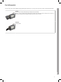
1
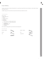
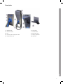
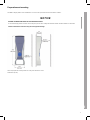
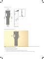
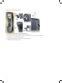
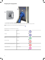
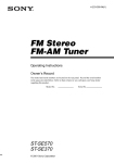
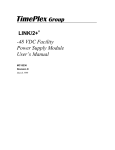
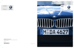
BMW i
Freude am Fahren
Installation Manual for BMW i Charging Station
2
Installation Manual for BMW i Charging Station
Installation instructions
Imprint
5
Hazard categories and special symbols
6
Warranty / Scope of delivery
7
Technical data
8
Description
9
Installation positions
10
Preparation and mounting
11
Wiring
16
Cable holder mounting
19
Energizing the charging station
20
Key locking system
21
Charging the vehicle
22
Troubleshooting
23
3
EN
Contents
4
Imprint
Order numbers
61 90 2 355 243
61 90 2 346 992
BMW i Charging Station, type T1 (16 A)
BMW i Charging Station, type T1 (30 A)
Publisher
B MW of North America, L LC
Woodcliff L ake (NJ ), United S tates of America
www.bmwna.com
Original installation instructions
Copyright ©2013 B MW of North America, L LC
Not to be reproduced wholly or in part without written permission of B MW NA. T he B MW name, model names and logo are registered trademarks. Other
trademarks and trade names are the property of their respective owners. P rinted in US A.
EN
P lease retain this document for future use.
5
Hazard categories and special symbols
Read these instructions carefully and look at the equipment to become familiar with the device before trying to install, operate, service, or maintain it. The following special messages may appear throughout this bulletin or on the equipment to warn of hazards or to call attention to information that clarifies or simplifies a procedure.
DANGER
DANGER indicates an imminently hazardous situation which, if not avoided, will result in death or serious injury.
WARNING
WARNING indicates a potentially hazardous situation which, if not avoided, can result in death or serious injury.
CAUTION
CAUTION indicates a potentially hazardous situation which, if not avoided, can result in minor or moderate injury.
NOTICE
NOTICE is used to address practices not related to physical injury. The safety alert symbol is not used with this signal word.
NOTE: Provides additional information to clarify or simplify a procedure.
Please note
Electrical equipment should only be installed, serviced, and maintained only by a qualified electrician. No responsibility is assumed by BMW or
Schneider Electric™ for any consequences arising out of the use of this material.
DANGER
BMW RECOMMENDS THAT ONLY A LICENSED, QUALIFIED ELECTRICIAN PERFORM THE INSTALLATION OF THE CHARGING
STATION
■
Prior to installation, obtain all required permits from the local permitting authority.
■
Remove the charging station and charging station cable from the carton and inspect for damage, such as a cracked or broken charging station housing
or cover, cracked or broken connector, or damaged output cable.
■
Installation must be performed in accordance with all applicable local codes.
Failure to follow these instructions will result in death or serious injury.
Information for domestic use
This equipment is designed for charging an electric vehicle indoors or outdoors with a shelter.
The BMW i Charging Station is exclusively used for charging BMW electrical vehicles with a compatible vehicle receptacle. If it is unknown whether the vehicle
is equipped with a compatible vehicle receptacle, please check the owner's manual.
The BMW i Charging Station must not be used for operating electrical devices other than BMW electric vehicles.
6
S c ope of delivery
T he purpose of this manual is to provide the installer with the necessary information to perform safe operation and maintenance of this equipment. Keep this
manual for future reference.
The BMW i C harging S tation must be installed and operated in the intended way described in this document.
S c ope of delivery
Package contents:
■
BMW i Charging Station
■
Wall plate
■
Installation instructions
■
User manual
■
Plastic bag with:
■
■
■
■
■
■
T hree screws # 10 x 2 in. (metric length: 50.80 mm)
Two screws # 10 x 0.25 in. (metric length: 6.35 mm)
Two locking keys
E ight wall mounting screws
Eight drywall anchors
Four washers
N O T E : Additional mounting hardware may be required for other mounting surfaces.
F lat-head screwdriver
Phillips ® screwdriver
Hammer
Pliers
Level
Torque wrench
EN
N ec es s ary tools
7
Technical data
Dimensions
Designation
Unit
Value
Height
in. (mm)
37.6 (955)
Width
in. (mm)
13.7 (349)
Depth
in. (mm)
16.1 (168)
Weight
lb. (kg)
37.5 (17)
Electrical data
Specifications
Reference standard
SAE J1772
UL® 2594, C22.2 No. 280-13, Electric Vehicle Supply Equipment
Rated current
16 A for 61 90 2 355 243
30 A for 61 90 2 346 992
Voltage
240 Vac single phase or 208Y (2 phases of a 3-phase system)
Frequency
60 Hz
Enclosure type
UL Type 3 for electrical parts in use
Operating temperature
-22 °F (-30 °C) to 122 °F (50 °C)
Storage temperature
-40 °F (-40 °C) to 176 °F (80 °C)
Use
Interior and exterior areas with weather protection
Charging station cable length
25 ft. (7.6 m)
Feeder circuit breaker (16 A)
Two pole 20 A
Feeder circuit breaker (30 A)
Two pole 40 A
8
Description
2
3
4
5
Start/Stop button
LED status indicator
Dock
Vehicle plug with charging station cable
Charging station cable
6
7
8
9
Product label
Information label
Key locking system
Storage compartment
10 Cable holder
EN
1
9
Installation positions
Installation of the BMW i Charging Station should be such that the following conditions are met:
■
The vehicle and charging station are unblocked by other items for ease of access, maintenance and emergency personnel
■
Closest proximity to the vehicle charge port to avoid tensioning of the charging station cable and wrapping the charging station cable around the vehicle
■
Avoid inhibiting vehicle access by vehicle occupants or causing a tripping hazard
10
Preparation and mounting
The BMW i Charging Station can be installed indoor or outdoor when protected from inclement weather conditions.
NOTICE
HAZARD OF PREMATURE AGING OF THE CHARGING STATION
Do not install charging station in locations where it may be exposed to direct sunlight and inclement weather. Sheltered install is recommended.
Failure to follow these instructions may result in equipment damage.
Select and prepare the mounting location according to the dimensions shown.
EN
All dimension (in./mm)
11
Dimensions (in. / mm)
Installing the wall mounting plate
NOTE: For concrete or brick wall mounting: use four concrete wall anchors (minimum ∅: 0.25 in. / 6.35 mm). Use steel bolts that match the anchor size and
thread. Mount in the brick/block, not in the mortar.
1
Remove the wall mounting plate (1) from the packaging.
2
Mount the wall mounting plate (1) to the wall using ...
■
■
12
either the two inner screw locations (2) with screws and washers provided for stud mounting,
or the four outer screw locations (3) with four screws, washers, and drywall anchors, provided for mounting directly to the wall.
Installing the branch circuit
1
Install the branch circuit as required by local electrical codes.
2
The wiring conduit (1) is to be placed in front of the wall mounting plate on the left side
3
The wiring conduit is to be placed in front of the wall mounting plate on the left side with 90 degree fitting facing out from the wall as shown.
4
The center of the fitting (3) shall line up with the corresponding arrow (2) on the wall mounting plate and be centered in the plate's
opening.
NOTE: Leave conduit loose to allow for movement during the installation process.
4
When wiring through the wall, the wires shall exit the wall and pass through the wall plate in the location shown, also lined up with the arrow (2) on the wall
mounting plate.
1
Remove screw (1) on top of the charging station.
2
Remove cover (8) of the charging station by pulling slightly forward (2), and then upward (3).
EN
Opening the charging station
NOTE: When wiring through the wall, step 3 is not required.
13
3
Using pliers, remove the cutout opening (7) for the wiring duct at the correct position in the cover plate (8).
4
Press in on the blue button on the front of the storage compartment to open the door. Remove the two screws (5) from storage compartment (6).
5
Remove storage compartment (6) from the charging station.
6
Remove the small cover (9) at the base of the charging station by pulling outward on the bottom edge.
Opening the electrical module
1
Loosen the six screws holding the electrical module cover in place and remove the cover (1).
2
Remove the knock-out in the back of the electrical module enclosure (2) near the wiring terminals for installation of the conduit fitting or cable clamp.
Installing the charging station on the wall mounting plate
1
Feed the wires and fitting through the knockout opening (4) in the electrical module.
2
Place the charging station on the two hooks (1 and 2) of the wall mounting plate.
3
Use the three provided #10 x 2 in. screws (3) and the two provided #10 x 0.25 in. screws (5) to secure the charging station on the wall mounting plate.
4
Secure the cable clamp (6) or conduit fitting (6) to the electrical module using the proper nut.
14
EN
NOTE: If the branch circuit conduit was left loose to allow for movement during the installation process, it can now be secured as required by local electrical
codes.
15
Wiring
DANGER
HAZARD OF ELECTRIC SHOCK, EXPLOSION, OR ARC FLASH
■
Read all instructions before using this product.
■
Apply appropriate personal protective equipment (PPE) and follow safe electrical work practices. See NFPA 70E or CSA Z462.
■
This equipment must only be installed and serviced by qualified electrical personnel.
■
High Voltage is present in the charging station (electric meter housing and power distribution service panel). Contact with high voltage can cause
death or serious injury.
■
Turn off all power supplying this equipment before working on or inside equipment.
■
Always use a properly rated voltage sensing device to confirm power is off.
■
Replace all devices, doors and covers before turning on power to this equipment.
■
Do not use this product if the enclosure is broken, cracked, open, or shows any other indication of
damage.
■
Do not use this product if there is any damage to the electric vehicle cable.
■
Do not change charging station connector.
■
Follow wiring instructions as marked on the equipment.
■
Ensure that the ambient temperature rating printed on the product nameplate is not exceeded.
■
Follow grounding instructions (see following pages).
■
For use only with electric vehicles where ventilation is not required.
■
This equipment has arcing or sparking parts that must not be exposed to flammable vapors. This equipment must be located at least 18 in. (460 mm)
above the floor.
■
To reduce the risk of fire, replace only with same type and ratings of fuse.
■
Do not use or modify this device to be portable. This device is to be used as permanently mounted equipment only.
Failure to follow these instructions will result in death or serious injury.
Wiring diagram
Grounding
This equipment must be connected to ground. An equipment-grounding conductor must be run with the circuit conductors and connected to the equipment
grounding terminal on the product.
16
WA R N IN G
H E AT A N D F IR E DA M A G E
F ollow the torque requirements specified on the back of the electrical module cover.
F ailure to follow thes e ins truc tions c an res ult in death, s erious injury or equipment damage.
Line Screw Torque Requirements
Wire Gauge
Torque (lb-in.)
AWG 14—10 Cu, Al
AWG 8 Cu, Al
35 (4,0 N•m)
40 (4,5 N•m)
Grounding Screw Torque Requirements
1
Wire the dedicated branch circuit to the electrical module as shown in the illustration.
2
T ighten the wire binding screws or lugs to the torque values located on the back of the electrical module cover.
Torque values for wire binding screws and lugs printed in this document are for reference only.
Wire Gauge
Torque (lb-in.)
AWG 14—10 Cu,
12—10 Al
20 (2,3 N•m)
AWG 8 Cu, Al
25 (2,8 N•m)
N O T E : Install grounding wire as specified by local electrical codes.
1
Align the cover with the base of the electrical module. B e certain that no wires are pinched under the cover.
2
T ighten the six screws in the electrical module cover to a torque of 20.0 lb-in. (2.3 N• m).
EN
R e- Ins talling the elec tric al module c over
17
Reassemble the charging station
1
Reinstall the storage compartment (1) in the charging station.
2
Reinstall the two screws (2) at the sides of the storage compartment.
3
Reinstall the top cover by sliding it down onto the top of the charging station (3), then pushing it back into place (4).
4
Reinstall the screw on top of the charging station (5).
5
Snap the small cover at the base of the charging station back into place (6).
6
Install the key in the key locking system (7).
18
Cable holder mounting
DANGER
HAZARD OF ELECTRIC SHOCK, EXPLOSION, OR ARC FLASH
■
Do not use this product if there is any damage to the electric vehicle cable.
■
Always position the charging station cable so that it will not be driven over, stepped on, tripped on, or otherwise damaged before each use.
■
Always properly stow the charging station cable after use.
Failure to follow these instructions will result in death or serious injury.
HAZARD OF STRANGULATION OR MISUSE
WARNING
■
Small children could become entangled in the charging station cable and be strangled. Keep small children away from the charging station and ALWAYS coil the cable on the cable holder and plug the connector into the dock located on the charging station when not in use.
■
Do not allow children to operate the charging station.
■
If the charging station cable becomes separated from the charging station, DO NOT attempt to repair the cable. Contact customer support at
877-400-7603 to arrange for service.
Failure to follow these instructions can result in death or serious injury.
NOTE: The bottom of the cable holder should be mounted so that the connector is stored between 18 in. (460 mm) and 48 in. (1,200 mm) from the floor.
1
Install the cable holder below or next to the charging station.
2
Mount on stud using the two center holes (1) and two screws provided, or four outer holes (2) using four screws and drywall anchors provided for direct
drywall mounting.
3
Coil the cable around the cable holder.
EN
NOTE: To avoid damage, always coil the cable on the cable holder and plug the connector into the dock located on the charging station when not in use.
19
Energizing the charging station
1
Turn on the branch circuit breaker (1) that feeds the charging station.
2
When energized, the LED indicator (2) will illuminate in blue, indicating that the BMW i Charging Station is ready for operation.
NOTE: If the LED indicator (2) is not blue, please refer to the troubleshooting section (p. 23).
Lighting behavior of the LED status indicator
Ready for charging
Solid blue
Charging
Flashes blue
Charging process interrupted with Stop/Start button
Solid green
Detected condition
Solid red
Detected condition with pending automatic reset
Flashes red
Charging station locked
Flashes magenta
20
Key locking system
The key locking system guards the BMW i Charging Station against unauthorized use. The key can be moved in two positions, LOCKED and UNLOCKED.
Locked
No connection to vehicle (cable unplugged): charging function deactivated.
Vehicle is connected (cable plugged): charging function shall be deactivated when vehicle is unplugged. Once vehicle is unplugged, the charging function is disabled until the key locking system is unlocked.
EN
Unlocked
Normal operation.
21
Charging the vehicle
Please see the operating instructions of your vehicle for information on connecting charging station cable the to the vehicle. The indicator next to the socket
on the vehicle is not active when the vehicle is in “sleep” mode.
Starting the charging process
1
Make sure the key on the charging station is in the unlocked position
NOTE: Be certain that the Stop/Start button is illuminated in blue. The blue color means that the BMW i Charging Station is waiting to start the charging
process and the vehicle is not yet connected, or that the vehicle is connected but currently in a charging break. If the LED does not illuminate in blue, please
refer to the troubleshooting section (see p. 23).
2
Connect the charging cable to the vehicle socket.
3
Charging begins as soon as the vehicle is ready to receive charge. While charging, the Stop/Start button flashes blue.
NOTE: The vehicle will not begin charging or will stop the charging process in the following situations:
■
The battery is completely charged.
■
The battery temperature is too high.
■
The loading management of the vehicle has interrupted the charging process.
■
A vehicle timer has delayed the start of charging.
Completing the charging process
Remove the charging station connector from the vehicle’s socket and replace it on the dock (see p. 9, pos. 3, for location of dock). The Stop/Start button will
illuminate in blue.
NOTE: The charging process may be stopped without removing the charging station connector by pressing the Stop/Start button. The Stop/Start button will
illuminate in green.
22
Troubleshooting
Detected condition reporting
The solid red LED indicates a detected condition. Press and hold the Stop/Start button for five seconds for condition reporting as described.
LED Status
Origin
Recommendation
Flashes red and yellow
BMW i Charging Station
Turn power feeding the charging station OFF and then back ON. If condition continues, have the charging station serviced by qualified personnel.
Flashes red and
green
Vehicle
Have the vehicle checked by a BMW i Center.
Flashes blue and
green
Vehicle / BMW i Charging Station communications
Turn power feeding the charging station OFF and then back ON. If condition continues, have the charging station serviced by qualified personnel.
- Have the charging station pilot signal tested.
- Have the vehicle checked by a BMW i Center.
Flashes red and blue
Wiring/cable/vehicle
Turn power feeding the charging station OFF and then back ON. If condition continues, have the charging station serviced by qualified personnel.
- Check supply circuit ground.
- Inspect cable for damage.
- Have the vehicle checked by a BMW i Center.
Detected condition memory
A memory feature allows the last detected condition type to be displayed.
1
With the charging station connector disengaged from the vehicle, the key locking system UNLOCKED, and blue LED illuminated (no detected condition
registered), press and hold the Stop/Start button for five seconds.
2
The stored detected condition memory will be reported as shown under Detected condition reporting.
3
If there are no detected conditions in the memory, the green LED flashes.
4
After one minute, the display will return to normal mode (solid blue LED).
NOTE: If the vehicle is plugged in (connected) for charging during the one-minute display of the condition memory, the display will return to normal and
charging will start without delay.
EN
NOTE: When the BMW i Charging Station is disconnected from the power supply system, the condition memory is cleared.
23
Mehr über BMW
www.bmw.de
www.bmw.com
01 29 2 355 276
09/2013
Freude am Fahren
Z/Z
Draft