1
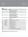
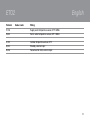
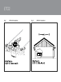
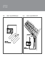
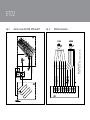
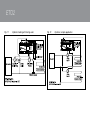
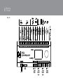
The world’s best-selling electric floor heating brand
Type E TO2
C ontroller for ic e
and s now melting
© 2011 Warmup Inc.
E nglis h
GR EEN C OMFOR T
Maxi mum comfort with low energy consumption
Type E TO2
Type E TO2 is an electronic controller for fully automatic,
economical ice and s now melting on outdoor areas and in
gutters . Ice forms due to a combination of low
temperature and mois ture. E TO2 detects both
temperature and mois ture, and the s now melting s ys tem
will us ually only be activated if s now or ice is pres ent.
E TO2 is s uitable for controlling electric heating cables , or
water-bas ed heating pipes .
P roduc t program
E TO2-4550-xxxx Thermos tat.
E TOG -55-xxxxx G round s ens or for detecting
temperature and mois ture.
E TOR -55-xxxxx G utter s ens or for detecting mois ture.
E TF-744/99
Outdoor s ens or for detecting
temperature
WAR NING ! – R ead this manual!
C arefully read this ins truction manual in its entirety,
paying clos e attention to all warnings lis ted below. Make
s ure that you fully unders tand the us e, dis plays and limitations of the controller, becaus e any confus ion res ulting
from neglecting to follow this ins truction manual, or from
2
E nglish
improper us e of this device, may caus e an ins taller to
commit errors , that may lead to ice & s now conditions
res ulting in s erious injury or death.
WAR NING ! – B e aware that s now, ic e and
ic eic les may be pres ent even if you follow the
ins truc tion or manual.
You are s trongly advis ed to follow any unexpected buildup of s now, ice layers or icicles . As an additional s afety
meas ure, you s hould always perform a manual ins pection
of public areas in order to s ecure s afety for acces s of the
controlled areas .
WAR NING ! – Important s afety ins truc tions .
Dis connect the power s upply before carrying out
any ins tallation or maintenance work on this control unit
and as s ociated components . This control unit and
as s ociated components s hould only be ins talled by a
competent pers on (i.e. a qualified electrician). E lectrical
ins tallation mus t be in accordance with appropriate
s tatutory regulations .
C E M AR K ING , F OR E U
OJ E lectronics A/S hereby declares that the product is
manufactured in accordance with C ouncil Directive
ETO2
2004/108/EC on electromagnetic compatibility (and
subsequent amendments) and Council Directive
2006/95/EEC on electrical equipment designed for use
within certain voltage limits.
Applied standards
ETO2-4550-EU28: CE marking LVD/EMC: EN60730-2-9
ETO2-4550-US28: CAN/CSA E 60730-2-9:01.
ETO2-4550-RU28: CE marking LVD/EMC: EN60730-2-9
The product may only be used if the complete installation
complies with current directives.
The product carries a manufacturer's warranty if installed
in accordance with these instructions and current
regulations.
If the product has been damaged in any way, e.g. during
transport, it must be inspected and checked by
authorised personnel before being connected to the
power supply.
Technical data
Thermostat ETO2-4550:
Designed to be mounted indoor only!
Supply voltage . . . . . . . . . .115/240V AC ±10%, 50-60 Hz
English
Built-in electronic power supply (SMPS) . . .24 V DC, 8 VA
3 output relays (potential-free contact, NO) . . . . .3 X 16 A
Alarm relay (potential-free contact, NO) . . . . . . . .max. 5 A
Control signal to actuator (mixing valve) . . . . . .0-10 V DC
Supply voltage to actuator
(mixing valve) . . . . . . . . . . . . . . . . . . . . .24 V AC / 100 mA
On/off differential . . . . . . . . . . . . . . . . . . . . . . . .1.8°F / 1°C
Temperature range . . . . . . . . . . . . . .-4/+50°F / -20/+10°C
Ambient temperature . . . . . . . . . . . . . .32/122°F / 0/+50°C
Ambient air humidity . . . . . . . . . . . . . . . . . . . . . . .10-95%
Enclosure rating . . . . . . . . . . . . . . . . . . . . .IP 20 / Nema 1
Weight
. . . . . . . . . . . . . . . . . . . . . . . . . . . . . . . . . .600 g
Dimensions H/W/D . . . . . . . . . . . . . . . . . . .90/156/45 mm
Type 1B
Control pollution degree 2
Rated impulse voltage . . . . . . . . . . . . . . . . . . . . . . . . .4 kV
Ground sensor type ETOG-55:
Designed to be embedded in outdoor areas.
Detection . . . . . . . . . . . . . . . . . .Moisture and temperature
Mounting . . . . . . . . . . . . . . . . . . . . . . . . . . . .Outdoor area
Enclosure rating . . . . . . . . . . . . . . . . . . . . . . . . . . . . .IP 68
Ambient temperature . . . . . . . . . .-57/+158°F / -50/+70°C
Dimensions . . . . . . . . . . . . . . . . . . . . . . . . . .H32, Ø60 mm
3
ETO2
Gutter sensor type ETOR-55:
Designed to be mounted in gutter or downpipe. Is used
together with outdoor sensor type ETF.
Detection . . . . . . . . . . . . . . . . . . . . . . . . . . . . . . . .Moisture
Mounting . . . . . . . . . . . . . . . . . . . . . . .Gutter or downpipe
Enclosure rating . . . . . . . . . . . . . . . . . . . . . . . . . . . . .IP 68
Ambient temperature . . . . . . . . . .-57/+158°F / -50/+70°C
Dimensions H/W/D . . . . . . . . . . . . . . . . . . .105/30/13 mm
Outdoor sensor type ETF-744/99:
Detection . . . . . . . . . . . . . . . . . . . . . . . . . . . . .Temperature
Mounting . . . . . . . . . . . . . . . . . . . . . . . . . . . . . . . . . . .Wall
Ambient temperature . . . . . . . . . .-57/+158°F / -50/+70°C
Dimensions H/W/D . . . . . . . . . . . . . . . . . . . .86/45/35 mm
Water sensor type ETF-1899A:
Detection . . . . . . . . . . . . . . . . . . . . . . . . . . . . .Temperature
Mounting . . . . . . . . . . . . . . . . . . . . . . . . . . . .Strap on pipe
Ambient temperature . . . . . . . . . . .-4/+158°F / -20/+70°C
Dimensions H/W/D . . . . . . . . . . . . . . . . . . . .86/45/35 mm
The snow and ice melting system is deactivated in the
event of sensor failure.
4
English
SENSOR INSTALLATION
Ground sensor ETOG, fig. 1+3:
For installation on outdoor areas where snow and ice is a
regular problem. The sensor must be embedded
horizontally with its top flush with the surroundings. Use
the accompanying installation plate.
The sensor cable must be installed in accordance with
current regulations. We recommend that cable pipes be
laid to protect the sensor cable. Detailed installation
instructions are supplied with the sensor.
Gutter sensor ETOR, fig. 2+4:
For installation in a gutter, or downpipe on the sunny side
of the building. It is important to ensure that the sensor
contact elements face against the flow of melt water. If
necessary, two sensors can be installed in parallel.
Detailed installation instructions are supplied with the
sensor.
Note that the pink and grey wires are not used.
ETO2
Outdoor sensor ETF-744/99, fig. 2+4:
ETF is for use with gutter sensor ETOR. ETF can also be
used separately for the detection of temperature alone.
The sensor should be mounted on the wall beneath the
eaves on the north side of the building.
Water sensor type ETF-1899A:
Only for use in waterbased system to detect temperature
in supply and return water. Must be fastened with strips
fixed directly on the pipe.
Sensor cables:
ETOG and ETOR are supplied with 10 m cable, which can
be extended up to approx. 200 m using standard
installation cable: 6x1.5 mm² for ETOG and 4x1.5 mm² for
ETOR. The ETF cable can be up to approx. 50 m in length.
Sensor cables must be installed in accordance with current
regulations. They must never be installed parallel to power
cables as electrical interference may distort the sensor
signal.
ETO2 installation
The unit is intended to be DIN-rail mounted in an
approved panel.
Wall mounting:
English
For USA and Canada: The thermostat can be wallmounted in a specially designed and UL-approved metal
box (accessory).
For other countries: The accompanying plastic cover can
be used for wall mounting in an indoor area.
Connect supply voltage to terminals N and L. All electrical
and mechanical installation must be performed in
accordance with applicable local regulations.
Setup:
• 1-zone electric heating control with ETOG (fig. 3+6):
Connect 1 or 2 ETOG sensors to terminals 11-20.
Connect heating cable to output relays 1, 2 and 3
according to fig. 8.
• 1-zone electric heating control with ETOR + ETF
(fig. 4+7):
Connect 1 or 2 ETOR sensors to terminals 11-20. Note
that the pink and grey wires are not used.
Connect 1 ETF sensor to terminals 31-32.
Connect heating cable to output relays 1, 2 and 3
according to fig. 8.
5
ETO2
• 2-zone electric heating control with ETOG (fig. 6):
Connect 2 ETOG sensors to terminals 11-20.
Connect heating cable for zone 1 to output relay 1
according to fig. 8.
Connect heating cable for zone 2 to output relay 2
according to fig. 8.
• 2-zone electric heating control with ETOR (fig. 7):
Connect 2 ETOR sensors to terminals 11-20. Note that
the pink and grey wires are not used.
Connect heating cable for zone 1 to output relay 1
according to fig. 8.
Connect heating cable for zone 2 to output relay 2
according to fig. 8.
• 2-zone electric heating control with ETOR and
ETOG (fig. 5+6+7):
Connect 1 ETOR sensor to terminals 11-16 as sensor
1. Note that the pink and grey wires are not used.
Connect 1 ETOG sensor to terminals 11-20 as sensor
2. Connect heating cable for zone 1 (roof) to output
relay 1 according to fig. 8.
Connect heating cable for zone 2 (ground) to output
relay 2 according to fig. 8.
6
English
• 1-zone electric heating control and output control
(Y/∆) (fig. 9+10):
Advanced 2-step control with ETOG-55. 1/3 power on
heating cables in afterrun.
Connect 1 or 2 ETOG sensors to terminals 11-20.
Connect external contactor/relays to output relays 1, 2
and 3 according to fig. 10.
• 1-zone hydronic heating control for control of
supply water temp. with mixing valve (fig. 6+11):
Connect 1 or 2 ETOG sensor to terminals 11-16.
Connect supply voltage (24 V AC) for mixing valve to
terminals 25-26 (fig. 13)
Connect mixing valve to terminals 21-24 (fig. 13).
Connect ETF 1899A supply and return sensors to
terminals 27-30.
Connect primary pump to output relay 1 according to
fig. 14.
Connect secondary pump to output relay 2 according
to fig. 14.
ETO2
• 1/2-zone hydronic heating control, simple (fig.
6+12):
Connect 1 or 2 ETOG sensors to terminals 11-20.
Connect circulation pump for zone 1 to output relay 1
according to fig. 14.
If zone 2 is used, connect circulation pump for zone 2
to output relay 2 according to fig. 14.
Application setup as for 1/2-zone electric heating
control, see User Manual, Startup.
• Remote control (fig. 15):
The forced heat and standby functions can be remotely
controlled by wiring ETO2 to external buttons/relays
(normally open).
Connect external standby button to terminals 33-34.
Connect external forced heat button to terminals 35-36.
English
TESTING SNOW MELTING SYSTEM
After completing installation and application setup, it is
recommended that the snow melting system be tested.
1. Adjust SET TEMP in the setup menu to max.
temperature.
2. Pour some water onto the sensor (ETOG/ETOR).
3. The output relay for the heating cable in the zone
concerned should activate and ON should be
indicated on the ETO2 display. Check that the
heating cable becomes warm, check the voltage if
possible.
4. After testing, adjust SET TEMP back to the desired
setting (factory setting = +3.0°C / 37.4°F).
7
ETO2
WIRING
Terminal
N, L
1, 2
3, 4
English
Colour code
5, 6
7, 8
11, 12
13, 14
15, 16
17, 18
19, 20
21, 22
23, 24
25, 26
brown/green
grey/pink
yellow/white
grey/pink
yellow/white
Wiring
Supply voltage, 120-240 V AC 50/60 Hz
Alarm relay (potential free) max. 5 A
Output relay 1, 16 A (potential free),
Heating cable 1 (zone 1) / Primary pump
Output relay 2, 16 A (potential free),
Heating cable 2 (zone 2) / Secondary pump
Output relay 3, 16 A (potential free),
Heating cable 3
Sensor heating 1+2, ETOG 1+2 and ETOR 1+2
Temperature sensor, ETOG 1
Moisture sensor 1, ETOG 1/ ETOR 1
Temperature sensor, ETOG 2
Moisture sensor, ETOG 2 / ETOR 2
3/4-way mixing valve, 0-10 V
3/4-way mixing valve, 24 V AC
24 V AC from external supply, for 3/4-way mixing valve
ETOR SENSOR WIRES : Note that the pink and grey wires are not used.
8
ETO2
Terminal
English
Colour code
Wiring
27, 28
29, 30
Supply water temperature sensor, ETF-1899A
Return water temperature sensor, ETF-1899A
31, 32
33, 34
35, 36
Outdoor temperature sensor, ETF
Standby, external input
Forced control heat, external input
9
ETO2
Environment protection and recycling
Help protect the environment by disposing of the
packaging and redundant products in a responsible
manner.
Product disposal
Products marked with this symbol must not be disposed
of along with household refuse, but must be delivered to a
waste collection centre in accordance with current local
regulations.
10
English
Figures
Fig. 1 Installation of ETOG ground sensor
1 Sensor
2 Installation plate
3 Heating element
Fig. 2 Installation of ETOR gutter sensor and
ETF outdoor sensor
1 Thermostat ETO2
2 Gutter sensor
3 Outdoor sensor
Fig. 3 One-zone electric heating with ETOG sensor
Fig. 4 One-zone electric heating with ETOR/ETF sensor
Fig. 5 Two-zone electric heating (roof/ground)
Fig. 6 ETOG connection
Fig. 7 ETOR connection
Fig. 8 Heating cable connection, example
Fig. 9 Two-stage electric heating control (Y/∆)
Fig. 10 Advanced 2-step connection Y/∆
Fig. 11 Hydronic heating with mixing valve
Fig. 12 Simple hydronic application
Fig. 13 Hydronic mixing valve connection
Fig. 14 Hydronic pump connection
Fig. 15 Connections for remote control of standby and
forced heat
Fig. 16 ETO2 controller, terminal overview
ETO2
Fig. 1
ETOG-55 Installation
Fig. 2
ETOR-55 Installation
ETO2
Fig. 3
Electric 1-zone with ETOG-55 sensor
Fig. 4
Electric 1-zone with ETOR-55 / ETF
ETO2
Electric 2-zone with ETOG, ETOR and ETF
Fig. 6
ETOG-55 connections
BR978A05c
© 2010 OJ Electronics A/S
Fig. 5
ETO2
Fig. 7
ETOR-55 connections
Fig. 8
Electric heating cable connections
ETO2
Advanced 2-step with ETOG-55. 1/3 power on
heating cables in afterrun.
Fig. 10
Advanced 2-step connections. 1/3 power on
heating cables in afterrun.
BR978A04a
© 2010 OJ Electronics A/S
Fig. 9
ETO2
Fig. 11
Hydronic heating with mixing valve
Fig. 12
Hydronic, simple application
ETO2
Fig. 13
Hydronic mixing valve connection
Fig. 14
Hydronic pump connection
ETO2
Fig. 15
Connection of Stand by & forced heat
FORCED
CONTROL
HEAT
ETO2
Fig. 16
ETO2
@ 2011 Warmup Inc.
ETO2
© 2011 OJ Electronics A/S
51
© 2011
Warmup Inc.
10 Kingsbridge Garden Cirdle, Suite 704
Mississauga, ON L5R 3K6
Tel.: 1-888-592-7687
www.warmup.ca