1
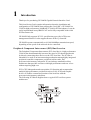
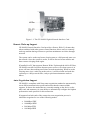
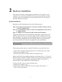
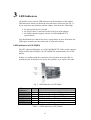
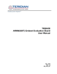
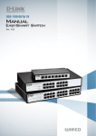
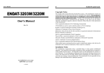
FCC Class B Statement
This device complies with Part 15 of the FCC Rules. Operation is subject to
the following two conditions:
•
•
This device may not cause harmful interference.
This device must accept any interference received, including
interference that may cause undesired operation.
Warning: This equipment has been tested and found to comply with the limits
for a Class B digital device, pursuant to Part 15 of the FCC Rules. These limits
are designed to provide reasonable protection. This equipment generates, uses
and can radiate radio frequency energy and, if not installed and used in
accordance with the instructions, may cause interference to radio
communications. However, there is no guarantee that interference will not
occur in a particular installation. If this equipment does cause harmful
interference to radio or television reception, which can be determined by
turning the equipment off and on, the user is encouraged to try to correct the
interference by one or more of the following measures:
•
•
•
•
Reorient or relocate the receiving antenna.
Increase the separation between the equipment and receiver.
Connect the equipment into an outlet on a circuit different from that to
which the receiver is connected.
Consult the dealer or an experienced radio/TV technician for help.
Notice: Shielded interface cable must be used in order to comply with
emission limits.
Notice: Changes or modification not expressly approved by the party
responsible for compliance could void the user’s authority to operate the
equipment.
CE Mark Statement
The 10/100BASE-TX Fast Ethernet Adapter has passed the test performed
according to European Standard EN 55022/A1 Class B, and EN 50 0821:1997(EN 61000-4-2:1995, EN 61 000-4-3:1996, EN 61 000-4-4:1995)
1
1
Introduction
Thank you for purchasing GE-2000N Gigabit Network Interface Card.
This Installation Guide contains information about the installation and
configuration of GE-2000N Network Interface Card (NIC). GE-2000N is a
32/64-bit high-performance 1000BASE-TX 64-bit PCI bus adapter. It can be
easily implemented in any IBM PC/AT and is fully compatible with 64-bit
PCI bus master slot.
GE-2000N fully supports PCI 2.2 specification to provide ACPI power
management function. It also supports Remote Wake-Up function.
GE-2000N operates automatically at 10/100/1000Mbps transmission speed,
depending on the speed of the network device connected.
Peripheral Component Interconnect (PCI) Bus Overview
The Peripheral Component Interconnect (PCI) local bus is a high-performance
32/64-bit bus that dramatically increases the speed of I/O-bound peripherals
by directly connecting these devices to the CPU local bus. The PCI bus is
intended to be used as an interconnecting mechanism among highly integrated
peripheral controller components, peripheral add-on cards, and
processor/cache/memory subsystem. It is an industry-standard local bus
architecture that provides end-users with high-performance and ease of use
without requiring high cost.
PCI is CPU-independent and can optimize I/O function and accommodate
multiple high-performance peripherals such as LAN, SCSI, and Graphic
devices. It enables concurrent operation of the local bus with the
processor/cache/memory subsystem.
The following PCI block diagram shows a typical PCI local bus system
architecture:
The processor/cache/memory subsystem connects the PCI local bus through a
PCI bridge. This bridge supports a low latency path through the processor, and
may directly access PCI devices mapped anywhere in the memory or I/O
address spaces. It also provides a high bandwidth path that allows PCI masters
to directly access the main memory.
Product Description
GE-2000N is a 32/64-bit PCI Gigabit Ethernet network interface card. It is
designed for use on computers with 64-bit PCI bus slots. GE-2000N runs in
bus master mode, directly sending/receiving Ethernet packets to/from
memory.
The PCI bus master device is an intelligent device that can conduct processing
independent of the bus or other devices. It coordinates the sharing of the bus
between the main processor and target devices. Bus mastering allows a
peripheral device to take control of the system bus instead of only relying on
the central processor.
GE-2000N complies with the IEEE 802.3u, IEEE 802.3, IEEE 802.3ab,
IEEE802.3x Full Duplex Flow Control and PCI Local Bus version 2.2, and
transmit data to the network at 10/100/1000Mbps. GE-2000N can also
operates in full-duplex mode to double the network speed up to
20/200/2000Mbps when working with a Ethernet/Fast Ethernet/Gigabit
Ethernet Switch. It is the fastest Ethernet design of its kind. GE-2000N
provides one RJ-45 port for connection with 10BASE-T Ethernet/100BASETX/1000BASE-TX Gigabit Ethernet network, and automatically senses the
connection type.
GE-2000N also supports ACPI (Advanced Configuration Power Management
Interface) and PCI power management for advanced operating systems that are
capable of OSPM (Operating System Directed Power Management) to achieve
most efficient power management.
The following figure shows the board layout of GE-2000N network interface
card:
3
Figure 1-1: The GE-2000N Gigabit Network Interface Card
Remote Wake-up Support
GE-2000N Network Interface Card provides a Remote Wake-Up feature that,
when combined with other remote control function, allows users to remotely
wake up machine during off hours to perform maintenance activities through
network.
The system can be woken up from a sleeping state to a full-powered state over
the network. Once the system is awake, it can be directed to run utilities and
then return to sleeping mode again.
If installed in a PC that supports Remote Wake-Up through the 64-bit PCI bus,
GE-2000N can still feed on an alternate power source even when system is in
power-off state, thus making an all-time network monitoring. When in such a
sleeping state, once a wake-up packet arrives, it will be alerted and wake the
system up to a full-powered state, ready to perform maintenance tasks or
others.
Auto-Negotiation Support
GE-2000N is compliant with Nway auto-negotiation standard to automatically
run at different transmission speeds and modes that the connected hub
supports. It detects the modes that are currently running on the device on the
other end, and announces its own ability to automatically configure the highest
performance mode possible for this connection.
If supported on both ends of the connection, auto-negotiation process is
initiated to negotiate for one of the following modes:
•
•
•
•
2000Mbps/FDX
1000Mbps/HDX
200 Mbps/FDX
100 Mbps/HDX
4
•
•
20 Mbps/FDX
10 Mbps/HDX
Features
•
•
•
•
•
•
•
•
•
•
•
•
•
Support 32/64-bit PCI Local Bus master for high throughput and low
processor utilization
Full comply with PCI Rev.2.2 and PC98/99 standard
Comply with the IEEE 802.3/IEEE 802.3u/IEEE 802.3ab standards
Support IEEE 802.3x Full Duplex Flow Control
Comply to ACPI (Rev 1.0), PCI Power Management (Rev 1.1), and
Device Class
Power Management reference Specification (V 1.0a), such as to support
OS Directed Power Management (OSPM) environment
Allow remote wake-up (Magic Packet, LinkChg and Microsoft wake-up
frame)
Support auxiliary power-on internal reset, to be ready for remote wake-up
when main power still remains off
Support 4 Wake-On-LAN (WOL) signals (active high, active low, positive
pulse, and negative pulse)
Plug and Play: Simply insert the card into a PC and it will automatically be
configured by the PC BIOS
Support full-duplex operation to double the network speed up to
20Mbps/200Mbps/2000Mbps
LED indicators to report network status
Provide single RJ-45 connector with auto-sensing for 10/100/1000Mpbs
network operation
What is ACPI Power Management?
ACPI (Advanced Configuration and Power Interface) is a power management
concept introduced by Intel, Toshiba and Microsoft in 1997. It is an open
industry standard, which includes PC hardware, Operating System and
peripheral device interface specifications. ACPI is one further step away from
the previous time-based power management system, which often turns off
peripherals at most inopportune moments without taking any potential needs
into management considerations. Conversely, ACPI is a demand-based power
management endeavor. It allows the collection of power consumption
information from the entire system and gives complete control of device
activity to the Operating System. Thus, ACPI enables the computer to provide
power only to those devices that need it and at the time when they need it with
the help of OS. Operating within a ACPI-enabled environment, GE-2000N
Gigabit Network Interface Card can take full advantage of its superior power
management feature to perform Remote Wake-up function in Power Down
mode.
This will contribute, together with your ACPI-compatible OS (such as
Windows 98 or Windows 2000) to a most economical PC power consumption.
5
According to the definition of ACPI, there are four Global System States that
are identified as the following 4 levels:
G0: normal operating state
G1: power-saving sleeping mode where the display and HD are shut
down to save power consumption. A trigger event will recover the
power-saving state to normal state.
G2: Power Down mode with minimum power consumption. The
minimum power is to offer the Wake-Up device such as
GE-2000N to activate and reboot the system from a cold start. The
Wake-Up On LAN NIC such as GE-2000N works at this level.
G3: The system is turned off by power switch. The power switch must
be turned ON to activate the system.
While the system is in Power Down mode, GE-2000N is still on the alert.
Once a Magic Packet addressed to the client computer is received by its WakeUP device ID such as GE-2000N NIC, it will trigger a sequence of events to
wake up the remote computer from sleeping state.
While there might still be other legacy systems which are not compatible with
ACPI, you might still preserve its original power saving feature if your system
components allowing it. But we will see a gradual migration to all ACPI
features in PC system. In order to fully benefit from the advantages of ACPI
power management, not only your PC has to be ACPI-compatible but also
your Operating System. However, an ACPI-compatible Operating System
running on a non-ACPI-compatible system might not give any benefits from
the OS-directed Power Management, since all power management will be
restricted within BIOS. The migration to ACPI power management is now
accelerating to a full speed in the PC industry. Systems using ACPI are
already on the market and we will see more in the near future. Since Microsoft
Windows 98 and the recent release of Windows 2000 are
fully ACPI-compatible and will incorporate OSPM (Operating System
Directed Power Management), ACPI will become a dominant Power
Management standard very soon.
Package Contents
Before you proceed further, please check and see whether you have all the
necessary accessories from the shipping package and make sure nothing is
missing. The complete package should include:
•
•
•
GE-2000N Network Interface Card
2 driver diskettes and/or Support CD-ROM
This Installation Guide (the electronic version can also be found on the
Support CD-ROM)
If any of these items is damaged or missing, please contact your authorized
network supplier.
6
2
Hardware Installation
This chapter will guide you through the installation of GE-2000N on your
computer. First, you must install the NIC on your system. Finally, you must
correctly connect and configure your network before the NIC can properly
function within your network.
Quick Installation
Basically, the NIC installation involves the following steps:
Step 1. Insert the network interface card into a 64-bit PCI master slot on
your PC motherboard.
Step 2. Use a twisted-pair cable to connect the Gigabit port on the NIC to
a Gigabit Switch.
Step 3. Configure your Network (Cable Connection Examples.)
The details of each step will be described in subsequent sections. Since GE2000N is a PCI-bus device, you will no longer need to configure this device
after installation. The system will automatically allocate its resources such as
I/O base address and IRQ at boot time. Simply follow the steps mentioned
previously and leave the system to configure for you automatically.
Step 1. Insert the network interface card into 64-bit PCI master slot on your
PC motherboard.
Follow the procedure below to install GE-2000N on your 64-bit PCI slot.
1. Turn off the computer and unplug the power cord from the power outlet.
2. Remove the computer cover.
3. Insert the NIC into an available 64-bit PCI expansion slot.
Note: A 64-bit PCI slot should be similar to one shown in Fig. 2-1. If you do
not know how to identify a 64-BIT PCI slot on your system, please check your
PC user manual or ask your system administrator. Make sure the NIC is
inserted firmly in the 64-BIT PCI bus-mastering slot.
4. Secure the NIC in the slot with a bracket screw.
5. Replace the computer cover.
6. If you want to insert another NIC into your system, repeat steps 1 - 5.
7. Turn on the system power.
7
Fig. 2-1 Insert the Gigabit NIC into the 64-bit PCI slot.
Notes:
•
Make sure that the PCI machine does support master slots, INT
multiple sharing and timing compatibility. Do not install GE-2000N in
a PCI slave slot. Please refer to your PCI system manual and select the
appropriate configuration settings.
•
When installing multiple GE-2000N adapters at one server, you should
configure INT settings of the 64-bit PCI slots correctly. Each GE2000N’s IRQ should not conflict with that of the other adapters
installed.
Step 2. Use a twisted-pair cable to connect the Gigabit port on the NIC to a
Gigabit Switch.
You must connect the NIC to the network before installing the network driver.
To connect the GE-2000N NIC to the network cable, follow these steps:
1. Connect the network cable to the RJ-45 Gigabit port on GE-2000N
NIC, as shown in Fig. 2-2.
2. Connect the other end of the network cable to a 10BASE-T or a
100BASE-TX network port.
3. Check the LEDs, as shown in Fig. 3-1a, Fig. 3-1b.
After installation of the network card, and you are now ready to install the
network driver.
8
Fig.2-2 Connecting the Network Cable to the RJ-45 Gigabit Port.
Please See Chapter 3 for more LED information.
Step 3. Configure your Network (Cable Connection Examples)
The NIC provides one RJ-45 Gigabit port for connecting to
10/100/1000BASE-TX Fast Ethernet network. The NIC will automatically
sense the transmission mode of the connection. For a detailed description of
the connection type, please refer to the followings:
Connecting to 1000BASE-TX Gigabit Ethernet Network
To connect the Gigabit NIC to a 10/100/1000BASE-TX Gigabit Ethernet
network, you need a twisted-pair Category 5 cable with RJ-45 connectors. The
connection distance is up to 100 meters maximum. Follow the steps below to
connect to Ethernet/Fast Ethernet/Gigabit Ethernet network:
1. Plug one end of the cable into the RJ-45 Gigabit port of the NIC.
2. Plug the other end of the cable into a Gigabit port of a Gigabit Ethernet
Switch (such as Ether-FSH24G) or a high-performance server with a gigabit
RJ-45 port.
Fig. 2-3 Connecting the Gigabit NIC to the Gigabit Switch.
9
Correct Network Cable (STP/UTP) Requirements
•
•
•
•
•
100/1000 Mbps network must be shielded twisted-pair (STP) or
Category 5 unshielded twisted-pair cable. Do not use Category 3,4
cable for 100 Mbps network operation, it could cause data loss.
Category 3 or 4 cable is good for 10Mbps network only.
Category 5 cable is also good for 10Mbps operation. If all network
uses UTP Category 5 cable, you may have the versatility to operate the
network at either 100Mbps or 10Mbps speed without recabling your
network due to cable category grade concern.
Depending on building codes, different insulation materials may be
required. Plenum-rated or TEFLON-coated wiring may be required in
some areas.
The wire gauge should be between 18 and 26 AWG. (Most telephone
installations use 24-gauge wiring.)
UTP wire should meet the following requirements :
o Solid copper
o Nominal capacitance : less than 16 pF/ft
o Nominal impedance : 100 Ohms
o Nominal attenuation : less than 11.5db.
10/100 Auto-negotiation (NWay)
GE-2000N NIC automatically runs at appropriate speed, depending on the
network device to which it is connected. It does this using NWay, a feature
that complies with the IEEE802.3 standard. It also works with any of other
IEEE-compliant products, including 10BASE-T, 100BASE-TX and
1000BASE-TX equipments.
10
3
LED Indicators
GE-2000N comes with six LED indicators on the backplane of the adapter.
LED indicators inform you about the network status as shown in the Fig. 3-1.
If you experience any problem with the adapter, first check the followings:
•
•
•
the appropriate driver is loaded
the proper cable is connected to the RJ-45 port of the adapter
the switch should complies with the 10/100/1000BASE-TX
specifications.
You should make sure that all the above requirements are met, then check the
LEDs again to make sure the connection is valid and working.
LED indicators of GE-2000N
The NIC supports full duplex at 10/100/1000BASE-TX. If the switch supports
NWay feature and full duplex, the GE-2000N NIC automatically runs in full
duplex.
If there is a problem with the connection, first check the network cable for
possible breach. If that does not resolve the problem, try to replace the cable.
Fig. 3-1 LED indicators of GE-2000N
LED
Indicators
10M
100M
1000M
LINK
ACT.
FUDUP
Status
Meaning
ON
ON
ON
ON
ON
ON
The port is operating at 10M speed
The port is operating at 100M speed
The port is operating at 1000M speed
A link has been established
Network activity is detected on the link
The port is operating at full duplex mode
Table 3-1 LEDs indicators of GE-2000N.
11
4
Diver Installation
Installing Network Drivers
You must install network driver to allow the NIC to work with your network
operating system. GE-2000N adapter card provides various network drivers on
the 2 driver diskettes. GE-2000N supports Windows 95/98/NT 4.0/2000,
Linux (kernel version 2.2.x), SCO Unix, Solaris Unix and Netware 4.x/5.x.
The followings provide you with the installation procedures for Windows
2000 Server.
Note:
For detailed information on the driver installation for each Operating System,
please refer to the relevant documentation file(s) in each corresponding
directory on the driver diskettes:
\win95 (GE-2000N-Win9598me.doc)
\win98 (GE-2000N-Win9598me.doc)
\winme (GE2000N-Win9598me.doc)
\winnt (note: the installation procedure is similar to Windows 2000)
\win2k (GE2000N-Win2k.doc)
\linux (GE2000N-linux.PDF and README.Linux)
\netware (GE2000N-NetWare.doc)
\sco
\solaris
Windows 95/98/Windows ME Driver Installation
Note: The driver installation steps for Windows 95/98/ME are very
similar with only very minor difference.
Step 1: After booting the Windows 2000, go to Control Panel and access
Add New Hardware. And the Add New Hardware Wizard appears.
12
Click Next. A dialog box will prompt you for Plug and Play device
search.
Again click Next. And Windows ME has detected a “PCI Ethernet
Controller” on your system.
Step 2: Select Search for the best driver for your device, and check Specify a
location, and click the Browse button.
13
On the Browse for Folder dialog box appears. Select A:\WINME
Step 3: On the Select Device dialog box, select the National Semiconductor
Corp. DP83820 Gigabit Network Controller.
Click OK. While copying files, your system is looking for the
DP83820.sys file, and you have to specify the a:\winme directory for
its location.
Click OK. The driver installation is complete.
14
Verifying your Windows 95/98/ME driver installation
Step 1: Go to Control Panel/System. On the System Properties sheet, click the
Device Manager tab. On the Device Manager, you can see the device name
appears on the list.
15
Windows 2000 Driver Installation
Step 1: After booting the Windows 2000, go to Control Panel and access
Add/Remove Hardware.
Click Next.
Step 2: Select Add/Troubleshoot a device.
Click Next.
Step 3: Select Add a new device.
16
Click Next.
Step 4: Select Yes, search for new hardware.
Click Next.
Step 5: Your system is now detecting for the presence of new hardware.
17
Step 6: Select Have Disk …. and access the Windows 2000 driver on the
diskette.
18
Step 7: The correct device name appears on the list.
Click Next.
Click Next to finish driver installation.
19
Verifying your Windows 2000 driver installation
Step 1: Go to Control Panel/System. On the System Properties sheet, click the
Hardware tab and access the Device Manager.
Step 2: On the Device Manager, you can see the device name appears on the list.
20
Appendix A Adapter Specifications
Standards:
IEEE 802.3 10BASE-T
IEEE 802.3u 100BASE-TX
IEEE 802.3ab 1000BASE-TX
IEEE 802.3x Full Duplex Flow Control
Bus Type:
32/64-bit PCI Bus Master
WakeOnLAN mode:
Support Magic Packet, LinkChg and Microsoft Wakeup frame
ACPI mode:
• Supports PCI bus Power Management Interface Spec
• D0, D1, D2, D3hot, and D3cold, 5 different power states
• PMEB (including LWAKE) can be generated form D1, D2,
D3hot and D3cold
• Magic Packet wakeup
• LinkChg wakeup
• Microsoft Wake Up frame
Transmission Speed:
IEEE 802.3u Auto-Negotiation
10/20 Mbps (Half/Full-duplex Ethernet),
100/200 Mbps (Half/Full-duplex Fast Ethernet)
1000/2000 Mbps (Half/Full-duplex Gigabit Ethernet)
LED Indicator:
10M
100M
1000M
FUDUP
ACT
LINK
Operating Temperature:
32 ~ 131 °F
0 ~ 55 °C
Storage Temperature:
-4 ~ 176 °F
-20 ~ 80 °C
Humidity:
10 ~ 90% RH non-condensing
21
Dimension (L x W):
16.3 x 8.1 cm
Operating Voltage:
+5V± 5% @ 300mA maximum.
22