1
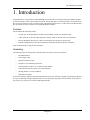
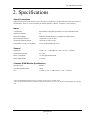
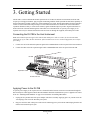
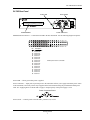
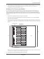
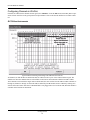
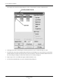
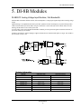
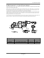
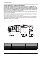
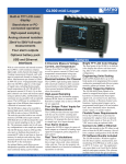
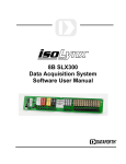
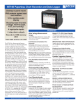
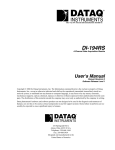
The way PC-based instrumentation should be DI-78B 8B Module Channel Expander for DI-720 and DI-730 Series Instruments User'sManual Manual Revision C Copyright © 2012 by DATAQ Instruments, Inc. The Information contained herein is the exclusive property of DATAQ Instruments, Inc., except as otherwise indicated and shall not be reproduced, transmitted, transcribed, stored in a retrieval system, or translated into any human or computer language, in any form or by any means, electronic, mechanical, magnetic, optical, chemical, manual, or otherwise without expressed written authorization from the company. The distribution of this material outside the company may occur only as authorized by the company in writing. DATAQ Instruments' hardware and software products are not designed to be used in the diagnosis and treatment of humans, nor are they to be used as critical components in any life-support systems whose failure to perform can reasonably be expected to cause significant injury to humans. DATAQ, the DATAQ logo, and WINDAQ are registered trademarks of DATAQ Instruments, Inc. All rights reserved. 241 Springside Dr. Akron, Ohio 44333 U.S.A. Telephone: 330-668-1444 Fax: 330-666-5434 Designed and manufactured in the United States of America M-100775 Warranty and Service Policy Product Warranty DATAQ Instruments, Inc. warrants that this hardware will be free from defects in materials and workmanship under normal use and service for a period of one year from the date of shipment. DATAQ Instruments' obligations under this warranty shall not arise until the defective material is shipped freight prepaid to DATAQ Instruments. The only responsibility of DATAQ Instruments under this warranty is to repair or replace, at its discretion and on a free of charge basis, the defective material. This warranty does not extend to products that have been repaired or altered by persons other than DATAQ Instruments employees, or products that have been subjected to misuse, neglect, improper installation, or accident. DATAQ Instruments shall have no liability for incidental or consequential damages of any kind arising out of the sale, installation, or use of its products. Service Policy 1. All products returned to DATAQ Instruments for service, regardless of warranty status, must be on a freight-prepaid basis. 2. DATAQ Instruments will repair or replace any defective product within 5 days of its receipt. 3. For in-warranty repairs, DATAQ Instruments will return repaired items to the buyer freight prepaid. Out of warranty repairs will be returned with freight prepaid and added to the service invoice. DI–78B Hardware Manual Table of Contents Warranty and Service Policy ................................................................................................................ 1. Introduction ........................................................................................................................................ Features .............................................................................................................................................. Unpacking .......................................................................................................................................... 2. Specifications ...................................................................................................................................... Signal Connections ............................................................................................................................ Inputs ................................................................................................................................................. General ............................................................................................................................................... Common DI-8B Module Specifications ............................................................................................ 3. Getting Started ................................................................................................................................... Connecting the DI-78B to the Host Instrument ................................................................................. Applying Power to the DI-78B .......................................................................................................... Features, Controls, and Indicators ..................................................................................................... DI-78B Front Panel ..................................................................................................................... DI-78B Rear Panel ...................................................................................................................... Installing DI-8B Modules .................................................................................................................. Enabling CJC for Thermocouple Modules ........................................................................................ Configuring Channels in WinDaq ..................................................................................................... DI-720 Host Instruments ............................................................................................................. DI-730 Host Instruments ............................................................................................................. Configuring Channel Gain (you MUST configure gain for proper readings) ............................ 4. Block Diagram .................................................................................................................................... 5. DI-8B Modules .................................................................................................................................... DI-8B30/31 Analog Voltage Input Modules, 3Hz Bandwidth .......................................................... DI-8B32 Analog Current Input Modules ........................................................................................... DI-8B34 Linearized 2- or 3-Wire RTD Input Modules .................................................................... DI-8B35 Linearized 4-Wire RTD Input Modules ............................................................................. DI-8B36 Potentiometer Input Modules ............................................................................................. DI-8B38 Strain Gage Input Modules, Narrow & Wide Bandwidth .................................................. DI-8B40/41 Analog Voltage Input Modules, 1kHz Bandwidth ........................................................ DI-8B42 2-Wire Transmitter Interface Modules ............................................................................... DI-8B43 DC LVDT Input Modules .................................................................................................. DI-8B45 Frequency Input Modules ................................................................................................... DI-8B47 Linearized Thermocouple Input Modules .......................................................................... DI-8B50/51 Analog Voltage Input Modules, 20kHz Bandwidth ...................................................... Table of Contents v iii 1 1 1 3 3 3 3 3 5 5 5 6 6 7 8 9 10 10 11 11 13 15 15 16 17 18 19 20 21 22 23 24 25 26 DI–78B Hardware Manual 1. Introduction Congratulations on your purchase of a DI-78B Backpack. The DI-78B is an analog in/analog out channel expander for DI-720 and DI-730 Series data acquisition systems. The DI-78B must be connected properly to a host DI-720 or DI-730 series instrument in order to acquire signals. This manual describes how to connect and use the DI-78B with DI-720 and DI-730 Series products as well as DI-8B amplifier modules. Features The DI-78B has the following features: • Accepts up to 16 DI-8B amplifier modules accommodating virtually any industrial signal. • Connects directly to the back panel expansion connector of DI-720 and DI-730 series instruments. • Powered through the host DI-720 or DI-730 unit using the provided power jumper cable. • Included stacking brackets allow the DI-78B to be stacked and mounted to the host instrument. Only one DI-78B may be used per host instrument. Unpacking The following items are included with each instrument. Verify that you have the following: • DI-78B Instrument. • Power jumper cable. • Expansion connector cable. • Screwdriver for connecting signal leads. • Sixteen jumpers to enable CJC for thermocouple modules. • Four removable sixteen position screw terminal blocks. • Stacking brackets (8 screws included). • This hardware manual. If an item is missing or damaged, call DATAQ Instruments at 330-668-1444. We will guide you through the appropriate steps for replacing missing or damaged items. Save the original packing material in the unlikely event that your unit must, for any reason, be sent back to DATAQ Instruments. Introduction 1 DI–78B Hardware Manual 2. Specifications Signal Connections Signal connections are made directly to the 4 removable 16-position screw terminal blocks located on the front of the instrument. There are 4 screw terminals per channel (channel+, channel-, excitation+, and excitation-). Inputs Configuration: Each channel is designed specifically to accept one DI-8B module Number of Channels: 16 Measurement Range: Defined by the 8B amplifier on a channel-by-channel basis.* Input-to-Output Isolation: ±1000 VDC or peak AC max Channel-to-Channel Isolation: ±500 VDC or peak AC max Temperature Accuracy (TC modules): ±0.5% of Full Scale Range ±2ºC** General Dimensions: 7.29W × 9L × 1.52H inches (18.52W × 22.86L × 3.86H cm) Operating Temperature: 0º to 70º C Power Consumption: 1.2 watts plus DI-8B module Power Requirements: 9-36 VDC Common DI-8B Module Specifications Input Protection: 240VAC Common Mode Rejection: 160db Size: 1.105W × 1.65L × 0.40H (2.81W × 4.19L × 1.02H cm) *Not all DI-8B amplifier modules support ± excitation, but all support ± channel inputs. **Does not include 8B module error. Ambient temperature range 20-25°C, still air, 12 watt max total 8B module power dissipation. Specifications 3 DI–78B Hardware Manual 3. Getting Started The DI-78B is a sixteen-channel 8B module expansion device for DI-720 and DI-730 instruments. Each DI-78B accepts up to 16 high performance, plug-in signal conditioning modules which expand the measurement capability of the host instrument to include virtually any isolated industrial-type signal. The DI-78B includes all cables required to connect to its host instrument and provide power. Each channel consumes one channel from its host instrument's expansion channel inventory in return for the isolated, signal-conditioned input it provides. Signal connections are made to the front of the DI-78B through four removable screw terminal blocks. A separate power supply is not required. Power may be obtained from the host DI-720 or DI-730 through the supplied, dual-ended power cable. Connecting the DI-78B to the Host Instrument Note: The included expansion signal cable and the dual ended power cable are sized to fit when the DI-78B is stacked on top of (or under) the host instrument. If the instruments are not in a stacked configuration, do so before proceeding. 1. Connect one end of the included expansion signal cable to EXPANSION on the rear panel of the host instrument. 2. Connect the other end of the expansion signal cable to EXPANSION IN on the rear panel of the DI-78B. DI-78B Expansion Cable DI-720 or DI-730 Applying Power to the DI-78B A separate power supply is not required. Power is obtained from the host DI-720 or DI-730 instrument through the dual-ended power cable supplied with the DI-78B. Modules should be installed before power is applied to the instrument. See “Installing DI-8B Modules” on page 8 for instructions on installing 8B modules. 1. Unplug the five-pin DIN end of the power adapter cable that is currently supplying power to your DI-720 or DI730 and plug it into one of the DI-78B’s power jacks. 2. Plug one end of the dual -ended power cable into the remaining power jack in the DI-78B and plug the other end into the host instrument power jack. Getting Started 5 DI–78B Hardware Manual 3. Plug the appropriate end of the power cord to a 120V source (wall outlet). DI-78B DI-720 or DI-730 To Power Adaptor Dual-Ended Power Cable Features, Controls, and Indicators The DI-78 front panel contains four removable sixteen position screw terminal blocks for quick and easy connection of all analog in signal leads. The rear panel provides connections for power and expansion in. DI-78B Front Panel The four 16-port screw terminals on the front of the DI-78B are used to interface analog input channels 1 through 16 (channels 17 through 32 of the host DI-720 or DI-730 instrument). Each channel has four terminals: In+, In-, Ex+, and Ex- for input signals and excitation (if required). Use the sticker located on the top of your instrument for quick reference to terminal access port designations. DI-78B Front Panel DI-78B Getting Started 6 DI–78B Hardware Manual DI-78B Rear Panel Power LED Power Switch EXPANSION IN Power Connectors EXPANSION IN connector — Connects the DI-78B to the host instrument. Use the following diagram for pinout. Pin 18 21 22 23 24 25 26 27 28 29 30 31 32 33 34 35 36 Description Analog Ground Channel 16 Channel 8 Channel 15 Channel 7 Channel 14 Channel 6 Channel 13 Channel 5 Channel 12 Channel 4 Channel 11 Channel 3 Channel 10 Channel 2 Channel 9 Channel 1 All other pins have no connection. Power LED — Glows green when power is applied. Power Connectors — Input jacks to provide power to the instrument. Allows you to apply an alternate power source to the instrument, if necessary. Power may be applied to the host instrument using the provided dual-ended power cable. See “Applying Power to the DI-78B” on page 5. Output capacity of the power supply is 2.5A. Power Connectors Pinout Power switch — Controls power to the DI-78B. 1 position is on, 0 is off. Getting Started 7 DI–78B Hardware Manual Installing DI-8B Modules DI-78B instruments accept up to 16 signal conditioned analog inputs. All DI-8B modules must be installed onto the DI-8B backplane (located on the instrument circuit board). 1. Unplug the device and make sure there is no power to the instrument. 2. Unscrew the six screws on the top of the instrument and remove the top hatch cover to reveal the DI-8B backplane. 3. Plug the DI-8B module firmly into one of the channel positions clearly labelled on the backplane and secure with the set screw. Note: Be sure to completely screw the module into place or vibrations could short the system. DI8B modules are installed on (or removed from) the socketed DI-8B backplane (located on the circuit board) and are secured with a non-removable mounting screw. Each channel position is labeled “CHANNEL 1,” “CHANNEL 2,” etc. on the socketed backplane. The DI-8B modules can be mixed or matched in any combination suitable for the application and are identical in pinout and size, so it doesn't matter which module gets plugged into which channel position. Top Hatch Set Screw DI-8B Module DI-8B Backplane and Circuit Board Rear Front 4. Using an erasable pencil write the module number of each DI-8B module installed on the sticker located on the top hatch to indicate which module is installed at each channel position. 101058-B Write Installed Modules in the spaces provided with an erasable pencil. Getting Started 8 DI–78B Hardware Manual 5. After all modules are installed and indicated on the sticker reassemble the instrument. Note: If your are installing a thermocouple module you must enable the Cold Junction Compensation jumper for that channel (see “Enabling CJC for Thermocouple Modules” below). Enabling CJC for Thermocouple Modules If you are installing a Thermocouple Input Module (see “DI-8B47 Linearized Thermocouple Input Modules” on page 25) you must enable the Cold Junction Compensation jumper. Each channel has its own CJC enable jumper located towards the front of the instrument on the instrument circuit board (see also “Installing DI-8B Modules” on page 8 for disassembly). Tip: Install all unused jumpers onto one pin of each channel so they cannot be accidentally misplaced. 1. Unplug the device and make sure there is no power to the instrument. 2. Unscrew the six screws on the top of the instrument and remove the top hatch cover to reveal the DI-8B backplane and the CJC Enable Jumpers. 3. Install a jumper onto the board for each channel that uses a thermocouple module. Each jumper is labelled on the circuit board as “TC CH#” where # is the channel number. Sixteen jumpers are provided with the DI-78B for this purpose. CJC Enable Jumpers Circuit Board with DI-8B Backplane CHANNEL 1 TC CH1 TC CH2 TC CH3 CHANNEL CHANNEL 2 CHANNEL 4 3 TC CH4 TC CH5 TC CH6 CHANNEL Rear 5 TC CH7 CHANNEL 6 CHANNEL 8 CHANNEL 10 CHANNEL 12 CHANNEL 14 CHANNEL 16 TC CH8 CHANNEL 7 Front CHANNEL 9 CHANNEL 11 TC CH9 Casing TC CH10 TC CH11 TC CH12 TC CH13 CHANNEL 13 TC CH14 TC CH15 TC CH16 CHANNEL 15 CJC Enable Jumpers Note: If you are not using a Thermocouple Input Module on that channel be sure the jumper is disabled (removed or installed on only one pin) because this will affect the input signal. 4. After all necessary jumpers are installed reassemble the instrument. Getting Started 9 DI–78B Hardware Manual Configuring Channels in WINDAQ Channels are enabled in the channel selection grid (select Channels... from the Edit menu) in WINDAQ Data Acquisition software. Each box in the grid represents an input channel. Click on the desired channel box to enable a channel. DI-720 Host Instruments Typical channel selection grid showing a DI-78B with a host DI-720 All channels (on both the DI-720 and the DI-78B) are enabled on the top row of the Channel Selection grid. The shaded areas show the channels that are still available on the host DI-720 instrument when the DI-78B is added. These channels can be enabled as single-ended or differential, the same as before the DI-78B was added. Channels 17 through 32 (channels 1 through 16 on the DI-78B) are defined by DI-8B modules and are enabled by clicking once with the left mouse button. Note that if a DI-8B module is not plugged into a slot on the DI-78B, then that channel is available on the host DI-720 instrument. Getting Started 10 DI–78B Hardware Manual DI-730 Host Instruments Typical channel selection grid showing a DI-78B with a host DI-730 All channels (on both the DI-730 and the DI-78B) are enabled on the top row of the Channel Selection grid. The shaded areas show the channels that are still available on the host DI-730 instrument when the DI-78B is added. Channels 17 through 32 (channels 1 through 16 on the DI-78B) are defined by DI-8B modules and are enabled by clicking once with the left mouse button. The isolated differential inputs on the front panel of the DI-730 are still available. Configuring Channel Gain (you MUST configure gain for proper readings) The signal conditioned (or DI-8B module) channels on the DI-78B output ±5 volts to the host instrument. Since the DI-78B connections to the DI-720 Series and DI-730 Series (available through the EXPANSION connector) host instruments are ±10 volt input devices, each DI-78B signal conditioned channel in use MUST be set to a gain of 2, so they have a full scale measurement range of ±5 volts. 1. After you have enabled channels, click on Channel Settings… in the Edit menu. Getting Started 11 DI–78B Hardware Manual This displays the Channel X Settings dialog box (where X represents the currently enabled channel). 2. In the upper left corner of the dialog box, click the gain factor 2 to get a ± full scale range of 5 volts. 3. Click the Next (or Previous) command button at the bottom of the dialog box to step to the next (or previously) enabled channel. Note that when either the Next or Previous button is activated, the channel number in the title bar of the dialog box changes to indicate the channel you are currently working on. 4. Repeat steps 2 and 3 for each DI-78B signal conditioned channel in use. 5. Click the OK command button to close the Channel Settings dialog box. Getting Started 12 DI–78B Hardware Manual 4. Block Diagram Typical Sixteen Positions To DI-720 or DI-730 EXPANSION Port 9-36VDC +5VDC Accessory Power Power Supply Power On Block Diagram 13 DI–78B Hardware Manual 5. DI-8B Modules DI-8B30/31 Analog Voltage Input Modules, 3Hz Bandwidth Each DI-8B30 or DI-8B31 module isolates, filters and amplifies a voltage input signal and provides an analog voltage output. Signal filtering is accomplished with a three-pole filter optimized for time and frequency response which provides 70dB of normal-mode-rejection at 60Hz. One pole of this filter is on the field side of the isolation barrier for antialiasing, and the other two are on the system side. A special input circuit on the DI-8B30 and DI-8B31 modules provides protection against accidental connection of power-line voltages up to 240VAC. Isolation is provided by optical coupling to suppress transmission of common mode spikes or surges. The module is powered from +5VDC, ±5%. : Ordering Information MODEL DI-8B30-01 DI-8B30-02 DI-8B30-03 DI-8B31-01 DI-8B31-02 DI-8B31-03 DI-8B31-07 DI-8B31-09 DI-8B31-12 INPUT RANGE -10mV to +10mV -50mV to +50mV -100mV to +100mV -1V to +1V -5V to +5V -10V to +10V -20V to +20V -40V to +40V -60V to +60V DI-8B Modules 15 OUTPUT RANGE -5V to +5V -5V to +5V -5V to +5V -5V to +5V -5V to +5V -5V to +5V -5V to +5V -5V to +5V -5V to +5V DI–78B Hardware Manual DI-8B32 Analog Current Input Modules Each DI-8B32 module isolates, filters and amplifies a process current input signal and provides an analog voltage output. Current to voltage conversion is accomplished internal to the module to ensure high accuracy. Signal filtering is accomplished with a three-pole filter optimized for time and frequency response which provides 70dB of normal-mode-rejection at 60Hz. One pole of this filter is on the field side of the isolation barrier for antialiasing, and the other two are on the system side. A special input circuit on the 8B32 module provides protection against accidental connection of power-line voltages up to 30VAC. Isolation is provided by optical coupling to suppress transmission of common mode spikes or surges. The module is powered from +5VDC, ±5%. Ordering Information MODEL DI-8B32-01 DI-8B32-02 INPUT RANGE 4mA to 20mA 0mA to 20mA DI-8B Modules 16 OUTPUT RANGE 0V to +5V 0V to +5V DI–78B Hardware Manual DI-8B34 Linearized 2- or 3-Wire RTD Input Modules Each DI-8B34 module isolates, filters, amplifies, and linearizes a single channel of temperature input from an RTD and provides an analog voltage output. RTD excitation is provided from the module using two matched current sources. When using a 3-wire connection, this method allows equal currents to flow through the sensor leads, cancelling the effects of lead resistances. The excitation currents are small (0.25mA) which minimizes the self-heating of the RTD. Signal filtering is accomplished with a three-pole filter optimized for time and frequency response which provides 70dB of normal-mode-rejection at 60Hz. One pole of this filter is on the field side of the isolation barrier for antialiasing, and the other two are on the system side. A special input circuit on the DI-8B34 module provides protection against accidental connection of power-line voltages up to 240VAC. Clamp circuits on the I/O and power terminals protect against harmful transients. Ordering Information MODEL DI-8B34-01 DI-8B34-02 DI-8B34-03 DI-8B34-04 INPUT RANGE OUTPUT RANGE ACCURACY* -100°C to +100°C (-148°F to +212°F) 0V to +5V ±0.20°C 0°C to +100°C (+32°F to +212°F) 0V to +5V ±0.15°C 0°C to +200°C (+32°F to +392°F) 0V to +5V ±0.20°C 0°C to +600°C (+32°F to +1112°F) 0V to +5V ±0.45°C * Includes conformity, hysteresis and repeatability. DI-8B Modules 17 DI–78B Hardware Manual DI-8B35 Linearized 4-Wire RTD Input Modules In RTD temperature measurement applications requiring a very high level of accuracy, the DI-8B35 4-Wire RTD input module offers a significant advantage over 3-wire measurement techniques (see block diagram). The DI-8B35 measures only the voltage dropped across the RTD and almost completely ignores the resistance or length of the RTD lead wires. The DI-8B34 3-Wire RTD module provides lead resistance compensation, but requires equal lead resistances, while the DI-8B35 does not require matched lead resistances. Each DI-8B35 module isolates, filters, amplifies, and linearizes a single channel of temperature input from an RTD and provides an analog voltage output. RTD excitation is provided from the module using a precision current source. Excitation current does not flow in the input signal leads, which allows RTD measurements to be made independent of lead resistance. The excitation currents are small (0.25mA) which minimizes self-heating of the RTD. Signal filtering is accomplished with a three-pole filter optimized for time and frequency response which provides 70dB of normal-mode-rejection at 60Hz. One pole of this filter is on the field side of the isolation barrier for antialiasing, and the other two are on the system side. A special input circuit on the DI-8B35 module provides protection against accidental connection of power-line voltages up to 240VAC. Clamp circuits on the I/O and power terminals protect against harmful transients. Ordering Information MODEL DI-8B35-01 DI-8B35-02 DI-8B35-03 DI-8B35-04 INPUT RANGE OUTPUT RANGE ACCURACY* -100°C to +100°C (-148°F to +212°F) 0V to +5V ±0.20°C 0°C to +100°C (+32°F to +212°F) 0V to +5V ±0.15°C 0°C to +200°C (+32°F to +392°F) 0V to +5V ±0.20°C 0°C to +600°C (+32°F to +1112°F) 0V to +5V ±0.45°C * Includes conformity, hysteresis and repeatability. DI-8B Modules 18 DI–78B Hardware Manual DI-8B36 Potentiometer Input Modules Each DI-8B36 module isolates, filters and amplifies a single channel of potentiometer input and provides an analog voltage output. Excitation for the potentiometer is provided by using two matched current sources. When using a 3-wire connection, this method allows equal currents to flow through the sensor leads, cancelling the effects of lead resistances. The excitation currents are small (0.25mA) which minimizes the self-heating of the potentiometer. Signal filtering is accomplished with a three-pole filter optimized for time and frequency response which provides 70dB of normal-mode-rejection at 60Hz. One pole of this filter is on the field side of the isolation barrier for antialiasing, and the other two are on the system side. A special input circuit on the DI-8B36 module provides protection against accidental connection of power-line voltages up to 240VAC. Clamp circuits on the I/O and power terminals protect against harmful transients. Ordering Information MODEL DI-8B36-01 DI-8B36-02 DI-8B36-03 DI-8B36-04 INPUT RANGE 0 to 100 0 to 500 0 to 1k 0 to 10k DI-8B Modules 19 OUTPUT RANGE 0V to +5V 0V to +5V 0V to +5V 0V to +5V DI–78B Hardware Manual DI-8B38 Strain Gage Input Modules, Narrow & Wide Bandwidth Each DI-8B38 module isolates, filters and amplifies a full-bridge strain gage input signal and provides an analog voltage output. The 8B38 can interface to transducers with a nominal resistance of 100 to 10k. Bridge excitation is provided from the module with a stable 10.00V or 3.33V source. Full scale sensitivities of 2mV/V and 3mV/V are offered as standard. Signal filtering is accomplished with a five-pole filter optimized for time and frequency response which provides 100dB per decade of normal-mode rejection above the filter cutoff frequency. One pole of this filter is on the field side of the isolation barrier for anti-aliasing, and the other four are on the system side. A special input circuit on the DI-8B38 module provides protection against accidental connection of power-line voltages up to 240VAC. Clamp circuits on the I/O and power terminals protect against harmful transients. Isolation is provided by optical coupling to suppress transmission of common mode spikes or surges. The module is powered from +5VDC, ±5%. Ordering Information MODEL DI-8B38-01 DI-8B38-02 DI-8B38-05 DI-8B38-31 DI-8B38-32 DI-8B38-35 BANDWIDTH 3kHz 3kHz 3kHz 3Hz 3Hz 3Hz INPUT RANGE -10mV to +10mV -30mV to +30mV -20mV to +20mV -10mV to +10mV -30mV to +30mV -20mV to +20mV EXCITATION OUTPUT RANGE 3.333V at 3mV/V Sensitivity -5V to +5V 10.0V at 3mV/V Sensitivity -5V to +5V 10.0V at 2mV/V Sensitivity -5V to +5V 3.333V at 3mV/V Sensitivity -5V to +5V 10.0V at 2mV/V Sensitivity -5V to +5V 10.0V at 2mV/V Sensitivity -5V to +5V DI-8B Modules 20 DI–78B Hardware Manual DI-8B40/41 Analog Voltage Input Modules, 1kHz Bandwidth Each DI-8B40 and DI-8B41 module isolates, filters, and amplifies a voltage input signal and provides an analog voltage output. Signal filtering is accomplished with a multiple pole filter optimized for time and frequency response which provides 70dB of normal-mode-rejection at 60Hz. One pole of this filter is on the field side of the isolation barrier for antialiasing, and the remaining poles are on the system side. A special input circuit on the DI-8B40 and DI-8B41 modules provides protection against accidental connection of power-line voltages up to 240VAC. Clamp Circuits on the I/O and power terminals protect against harmful transients. Isolation is provided by optical coupling to suppress transmission of common mode spikes or surges. The module is powered from +5VDC, ±5%. Ordering Information MODEL DI-8B40-01 DI-8B40-02 DI-8B40-03 DI-8B41-01 DI-8B41-02 DI-8B41-03 DI-8B41-07 DI-8B41-09 DI-8B41-12 INPUT RANGE -10mV to +10mV -50mV to +50mV -100mV to +100mV -1V to +1V -5V to +5V -10V to +10V -20V to +20V -40V to +40V -60V to +60V DI-8B Modules 21 OUTPUT RANGE -5V to +5V -5V to +5V -5V to +5V -5V to +5V -5V to +5V -5V to +5V -5V to +5V -5V to +5V -5V to +5V DI–78B Hardware Manual DI-8B42 2-Wire Transmitter Interface Modules Each DI-8B42 module provides power to a current transmitter, then isolates, filters and amplifies the resulting process current input signal and provides an analog voltage output. Current to voltage conversion is accomplished internal to the module to ensure high accuracy. Signal filtering is accomplished with a three-pole filter optimized for time and frequency response which provides 60dB per decade of normal-mode rejection above 100Hz. One pole of this filter is on the field side of the isolation barrier for anti-aliasing, and the other two are on the system side. A special input circuit on the DI-8B42 module provides protection against accidental connection of power-line voltages up to 40VAC. Clamp circuits on the I/O and power terminals protect against harmful transients. Isolation is provided by optical coupling to suppress transmission of common mode spikes or surges. The module is powered from +5VDC, ±5%. Ordering Information MODEL DI-8B42-01 DI-8B42-02 INPUT RANGE 4mA to 20mA 4mA to 20mA DI-8B Modules 22 OUTPUT RANGE 0V to +5V +1V to +5V DI–78B Hardware Manual DI-8B43 DC LVDT Input Modules Each 8B43 module isolates, filters, and amplifies a voltage input signal and provides an analog voltage output. The 8B43 can interface to transducers that will operate on a 10V excitation voltage and up to 20mA of excitation current. Signal filtering is accomplished with a 5-pole filter optimized for time and frequency response which provides 100dBper decade of normal-mode rejection above 1kHz. One pole of this filter is on the field side of the isolation barrier for anti-aliasing, and the other four are on the system side. A special input circuit on the 8B43 modules provides protection against accidental connection of power-line voltages up to 240VAC. Clamp circuits on the I/O and power terminals protect against harmful transients. Isolation is provided by transformer coupling to suppress transmission of common mode spikes or surges. The module is powered from +5VDC, ±5%. Ordering Information MODEL DI-8B43-01 DI-8B43-02 DI-8B43-03 DI-8B43-04 DI-8B43-05 DI-8B43-11 DI-8B43-12 DI-8B43-13 DI-8B43-14 DI-8B43-15 INPUT RANGE -1V to +1V -2V to +2V -3V to +3V -4V to +4V -5V to +5V -1V to +1V -2V to +2V -3V to +3V -4V to +4V -5V to +5V DI-8B Modules 23 OUTPUT RANGE -5 to +5V -5 to +5V -5 to +5V -5 to +5V -5 to +5V 0 to +5V 0 to +5V 0 to +5V 0 to +5V 0 to +5V DI–78B Hardware Manual DI-8B45 Frequency Input Modules Each DI-8B45 module isolates and conditions a frequency input signal and provides an analog voltage output. The frequency input signal can be either a TTL level or zero crossing with as little as ±100mV amplitude. Input circuitry for each signal type has built-in hysteresis to prevent spurious noise from corrupting the module output. TTL signals are applied to the + and - terminals while zero crossing signals are applied to the +EXC and - terminals. Reference the block diagram. A 5V excitation is available for use with magnetic pick-up or contact closure type sensors. The excitation is available on the -EXC terminal with return on the - terminal. A special input circuit on the DI-8B45 modules provides protection against accidental connection of power-line voltages up to 240VAC. Clamp circuits on the I/O and power terminals protect against harmful transients. Isolation is provided by optical coupling to suppress transmission of common mode spikes or surges. The module is powered from +5VDC, ±5%. Ordering Information MODEL DI-8B45-01 DI-8B45-02 DI-8B45-03 DI-8B45-04 DI-8B45-05 DI-8B45-06 DI-8B45-07 DI-8B45-08 INPUT RANGE 0 to 500Hz 0 to 1kHz 0 to 2.5kHz 0 to 5kHz 0 to 10kHz 0 to 25kHz 0 to 50kHz 0 to 100kHz OUTPUT RANGE 0 to +5V 0 to +5V 0 to +5V 0 to +5V 0 to +5V 0 to +5V 0 to +5V 0 to +5V DI-8B Modules 24 EXCITATION +5V at 8mA max +5V at 8mA max +5V at 8mA max +5V at 8mA max +5V at 8mA max +5V at 8mA max +5V at 8mA max +5V at 8mA max DI–78B Hardware Manual DI-8B47 Linearized Thermocouple Input Modules Each DI-8B47 module isolates, filters, amplifies, and linearizes a single channel of temperature input from a thermocouple and provides an analog voltage output. Linearization is accomplished using a four breakpoint piece wise linear approximation. The DI-8B47 can interface to industry standard thermocouple type J, K, and T and has an output signal of 0V to +5V. Each module is cold-junction compensated to correct for parasitic thermocouples formed by the thermocouple wire and screw terminals on the mounting backpanel. Upscale open thermocouple detect is provided by an internal pull-up resistor. Signal filtering is accomplished with a three-pole filter optimized for time and frequency response which provides 70dB of normal-mode-rejection at 60Hz. One pole of this filter is on the field side of the isolation barrier for antialiasing, and the other two are on the system side. A special input circuit on the DI-8B47 module provides protection against accidental connection of power-line voltages up to 240VAC. Note: The temperature accuracy of these thermocouple modules when used with the DI-78B is ±2ºC @25ºC. Ordering Information MODEL DI-8B47J-01 DI-8B47J-02 DI-8B47J-03 DI-8B47J-12 DI-8B47K-04 DI-8B47K-05 DI-8B47K-13 DI-8B47K-14 DI-8B47T-06 DI-8B47T-07 TYPE INPUT RANGE ACCURACY* Type J 0°C to +760°C (+32°F to +1400°F) ±0.24% ±1.82°C Type J -100°C to +300°C (-148°F to +572°F) ±0.24% ±0.96°C Type J 0°C to +500°C (+32°F to +932°F) ±0.21% ±1.05°C Type J -100°C to +760°C (-148°F to +1400°F) ±0.24% ±2.10°C Type K 0°C to +1000°C (+32°F to +1832°F) ±0.24% ±2.40°C Type K 0°C to +500°C (+32°F to +932°F) ±0.24% ±1.05°C Type K -100°C to +1350°C (-148°F to +2462°F) ±0.24% ±3.60°C Type K 0°C to +1200°C (+32°F to +2192°F) ±0.24% ±2.88°C Type T -100°C to +400°C (+32°F to +392°F) ±0.48% ±2.40°C Type T 0°C to +200°C (+32°F to +392°F) ±0.39% ±0.75°C *Includes conformity, hysteresis and repeatability. Does not include CJC accuracy. DI-8B Modules 25 DI–78B Hardware Manual DI-8B50/51 Analog Voltage Input Modules, 20kHz Bandwidth Each DI-8B50 and DI-8B51 module isolates, filters, and amplifies a voltage input signal and provides an analog voltage output. Signal filtering is accomplished with a multiple pole filter optimized for time and frequency response which provides 70dB of normal-mode-rejection at 60Hz. One pole of this filter is on the field side of the isolation barrier for antialiasing, and the remaining poles are on the system side. A special input circuit on the DI-8B50 and DI-8B51 modules provides protection against accidental connection of power-line voltages up to 240VAC. Clamp circuits on the I/O and power terminals protect against harmful transients. Isolation is provided by optical coupling to suppress transmission of common mode spikes or surges. The module is powered from +5VDC, ±5%. Ordering Information MODEL DI-8B50-01 DI-8B50-02 DI-8B50-03 DI-8B51-01 DI-8B51-02 DI-8B51-03 DI-8B51-07 DI-8B51-09 DI-8B51-12 INPUT RANGE -10mV to +10mV -50mV to +50mV -100mV to +100mV -1V to +1V -5V to +5V -10V to +10V -20V to +20V -40V to +40V -60V to +60V DI-8B Modules 26 OUTPUT RANGE -5V to +5V -5V to +5V -5V to +5V -5V to +5V -5V to +5V -5V to +5V -5V to +5V -5V to +5V -5V to +5V DATAQ Instruments, Inc. 241 Springside Drive Akron, Ohio 44333 Telephone: 330-668-1444 Fax: 330-666-5434 E-mail: [email protected] Direct Product Links (click on text to jump to page) Data Acquisition | Data Logger | Chart Recorder