1
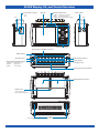
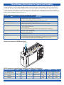
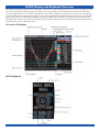
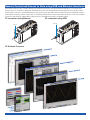
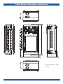
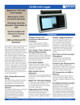
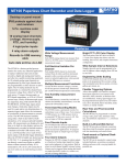
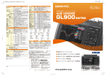
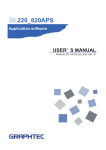
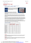
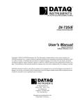
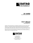
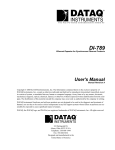
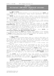
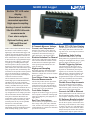
GL900 midi Logger
Built-in TFT LCD color
display
Stand-alone or PCconnected operation
High-speed sampling
Analog channel isolation
20mV to 500V full-scale
measurements
Four alarm outputs
Optional battery pack
USB and Ethernet
Interfaces
With its color monitor and internal memory
the GL900 is a self-contained, compact,
lightweight, multi-channel data logger with
8 analog measurement channels, each with
input-to-output and channel-to-channel isolation. Measurements per channel of 20mV
to 500V FS across 14 programmable ranges
allow the GL900 to adapt to a wide range
of signal types, including thermocouplebased temperatures (K,J,E,T,R,S,B,N,W)
and process current (4-20 mA). Up to four
pulse channels can count and measure speed
using an optional cable, and Humidity measurements are also possible with an optional
sensor. The GL900 may be configured to
trigger up to four different alarm outputs as
a function of measured values.
The GL900 allows data to be recorded to
internal high-speed volatile RAM memory
(64 MB) at rates as fast as 100,000 Hz.
The unit also provides built-in non-volatile
memory (256 MB) and accepts external
USB flash drives (2 GB maximum file size)
for lower speed sampling as fast as 1,000
Hz. The minimum sample rate for all memory configurations is one sample per minute.
The GL900 features built-in USB and Ethernet ports to facilitate data transfer to a
connected PC either in real time or from its
memory for analysis and archiving. Measurement protocols may also be uploaded
from the PC to the instrument.
An optional battery pack allows powerindependent operation and failsafe measurement continuity during a power failure.
Features
8 Channels Measure Voltage,
Current, and Temperature
Measure from 20mV to 500V full scale,
as well as process current (4-20mA) and
temperature measurements using type
J,K,E,T,R,S,B,N, or W thermocouples.
Bright TFT LCD Color Display
The focal point of the GL900 is its built-in
color display that allows real time trending, data review, and complete instrument
configuration.
Engineering Units Scaling
Electrical Isolation Per Channel Each GL900 channel allows up to four
The GL900’s eight analog input channels
offer electrical isolation to allow accurate
measurements in industrial applications
where ground potential differences are
often encountered.
High-speed Sampling
Depending upon the destination memory
(internal RAM, flash, or external USB
flash drive) sample rates as fast as 100,000
Hz are supported.
Four Unique ‘Pulse’ Inputs for
Discrete Measurements
The GL900 provides discrete input channels that can be used for counting and
rotational speed or flow measurement applications. Or program the discrete inputs
as simple logic level input channels.
Four Alarm Outputs
Program the GL900 to trigger its open-collector outputs as a function of analog input
signal level judgment, pulse judgment, or
logic pattern.
Real Time Calculations
The GL900 may be programmed to calculate average value, peak value, minimum
value, and rms. You can also generate calculated channels as a function of arithmetic
operations in real time.
break points to be programmed for accurate
scaling into meaningful units like psi, grams,
newtons, gallons per minute, liters, etc.
Flexible Triggering Options
The GL900 allows data capture to be
started or stopped based upon a manual
keystroke or automatically based upon
signal level, an external event, date/time,
alarm, duration, or Boolean channel combinations. Analog signal triggers can be
programmed based upon level and window
tests: above threshold, below threshold,
inside window, or outside window.
Flexible Power Requirements
Power the GL900 from its provided international AC adaptor, from an optional
built-in battery pack, or from any 9 to 24
VDC source using an optional cable.
Connect via USB or Ethernet
Allows data transfer to the PC either in real
time or from the GL900’s memory. Also allows complete configuration of the GL900.
PC Software Bundle Included
The GL900 includes a Windows application for direct capture, measurement, and
monitoring of GL900 data as well as analysis (FFT, X-Y plots, etc). The application
can export data to an Excel file for further
analysis and report creation. The software
includes built-in help for quick reference.
DATAQ Instruments, Inc. • 241 Springside Drive • Akron, Ohio 44333 • Tel: 330-668-1444 • Email: [email protected] • www.dataq.com
GL900 Display, I/O, and Control Overview
PC interface terminals
Fan
Monitor
Operation status LED
• USB
• LAN
• POWER : ON when the power is ON
• START : ON during data capture
• CHARGE : ON while the battery is charging
Power switch
Fan
Control panel keys
Analog signal input BNC connector
GND terminal
USB memory terminal
AC adapter jack
Power jack for
humidity sensor
External input/output terminal
• LOGIC/PULSE : LOGIC/PULSE input
• EXT TRIG
: Trigger input
• ALARM
: Alarm output
Analog signal input terminals
Model imprint and others
Battery cover
Contains battery packs
(B-517: Option) sold separatel.
Stands
Before using the stands, read the precautions provided in Section 1.3 "Operating Environment".
330-668-1444
2
www.dataq.com
GL900 Isolated Analog Input Connections
The GL900 connects to almost any analog signal type that you want to measure -- from millivolts to hundreds of volts; from process
current to humidity and temperature. Each channel is accessible through either a screw terminal pair or a BNC connector. Thermocouple connections are made directly to the terminal strips, which also easily accommodate an external shunt resistor for process current
measurements.
Terminal configuration and signal types
CH8 . . . . . . . . . . . . . . . . . . . . . . . . . . . . . . . . . . . . . . . . . . . . CH1
Positive Input Terminal
Negative Input Terminal
Screw type terminal
BNC connector
The screw type terminal and the BNC connector are internally connected. Data entered to either of them can be measured.
Connection diagram and measurement types
Direct voltage input
Thermocouple input
Direct current input
Compensation
copper wire
Direct current
2.5
Direct voltage
Shunt resistor
Example: If 4-20 mA is used, connect
a 250 Ω ( ±0.1%) resistor and measure
it in the 1-5 V range.
Measurement types and ranges
Item
Description
Input Configuration
Isolated Input
Analog Voltage
Analog voltage 20, 50, 100, 200, 500 mV/F.S.; 1, 2, 5, 10, 20, 50, 100, 200, 500V/F.S.; 1-5V
Thermocouple
K, J, E, T, R, S, B, N, W (WRe 5-26)
A/D resolution
16-bit
Filter
Off, Line, 5, 50, 500Hz
www.dataq.com
3
330-668-1444
GL900 Logic, Pulse, Alarm, and External Trigger Connections
The optional Logic Alarm Cable model B-513 provides access to the GL900’s discrete and pulse inputs, and alarm outputs. The cable
is two meters in length, and is purchased separately. The GL900 supports frequency measurements, pulse counting, discrete inputs,
and alarm outputs.
Logic alarm cable (B-513: option)
Wiring
Cable tips are bare tips. Perform wiring for the necessary
functions
Signal Name
Channel Number
Logic/Pulse
Output*
Alarm Output
Wire Color
1
Orange with red dotted line
2
Orange with black dotted line
3
Grey with red dotted line
4
Grey with black dotted line
1
White with red dotted line
2
White with black dotted line
3
Yellow with red dotted line
4
Yellow with black dotted line
Trigger Input
Pink with red dotted line
GND
Pink with black dotted line
Shielded
Orange with red dotted line
:1
Orange with black dotted line : 2
Grey with red dotted line
:3
Grey with black dotted line
:4
White with red dotted line
:1
White with black dotted line
:2
Yellow with red dotted line
:3
Logic/Pulse input
Alarm output
Yellow with black dotted line : 4
Pink with red dotted line
: Trigger input
Pink with black dotted line
GND
Shielded
Trigger Input Specifications
Item
Logic/Pulse Specifications*
Description
Item
Description
Number of input channels
1
Number of input channels
4
Input voltage range
0 to +24V max. (single-ended ground input)
Input voltage range
0 to +24V max. (single-ended ground input)
Threshold level
Approx. +2.5V
Threshold level
Approx. +2.5V
Hysteresis
Approx. 0.5 V (+2.5 to +3 V)
Hysteresis
Approx. 0.5 V (+2.5 to +3 V)
Typical Alarm Output Implementation
Alarm Output Circuit
GL900
External Device
Alarm Output Specifications
Item
+24V
+5V
10K Ω
Number of output channels
4
Output format
Open collector output
+5 V, 10 KΩ pull-up resistance
Contact capacity 5 V to 24 V, 100 mA or
below
*Switch between logic and pulse
This relay turns ON when alarm is generated.
330-668-1444
Description
4
www.dataq.com
Flexible Triggering Options Add Versatility
The GL900 adapts to just about any trigger condition you might encounter. Using its combination of trigger and timer functions
eliminates superfluous data and enables capture of only the required data. Data recording can be stopped or started manually or as
a function of analog signal level, an external event, or specific date and time. Beyond initiating a data capture cycle, the GL900 can
be programmed to set digital outputs to flag up to four external alarm conditions. And after a trigger condition is executed you can
program the GL900 to automatically rearm itself to wait for another trigger event, or stop entirely. Completing the trigger picture, the
GL900 also supports pre-triggering so you can see events leading up to a trigger event – perfect for cause-and-effect troubleshooting.
Setting
Selections Available
Timer Mode
Off, Date and Time, Every Day Cycle, Every Hour Cycle
[Date and Time]
Date
January 1, 2005 to December 31, 2035
Time
00:00 to 23:59 (Hour:Minute)
Date
January 1, 2005 to December 31, 2035
Time
00:00 to 23:59 (Hour:Minute)
Start side source setting
Time
00:00 to 23:59 (Hour:Minute)
Stop side source setting
Time
00:00 to 23:59 (Hour:Minute)
Start side source setting
Time
00:00 to 59:59 (Minute:Second)
Stop side source setting
Time
00:00 to 59:59 (Minute:Second)
Start side source setting
Stop side source setting
[Every Day Cycle]
[Every Day Cycle]
Start side source setting
[Level]
Off, Level, External Input
Combination
Level OR, Level AND, Edge OR, Edge AND
Mode
Analog : Off, ↑ H, ↓ L, Win In, Win
Logic : Off, ↑ H, ↓ L
Pulse : Off, ↑ H, ↓ L
Level
Numeric value setting
Stop side source setting
Off. Level, External Input, Time
[Level]
Combination
Level OR, Level AND, Edge OR, Edge AND
Mode
Analog : Off, ↑ H, ↓ L, Win In, Win
Logic : Off, ↑ H, ↓ L
Pulse : Off, ↑ H, ↓ L
Level
Numeric value setting
[Time]
0000:00:01 to 9999:59:59 (Hour:Minute:Second)
Pre-trigger
0, 10, 20, 30, 40, 50, 60, 70, 80, 90, 100%
Repeated capturing
Off, On
Repeat interval
0000:00 to 9999:59 (Hour:Minute)
Timer trigger information
▼Display Information
Alarm Level
Settings
Alarm Hold
On, Off
Mode
Analog : Off, ↑ H, ↓ L, Win In, Win Out
Logic : Off, ↑ H, ↓ L
Pulse : Off, ↑ H, ↓ L, Win In, Win Out
Level
Numeric value setting
Output
1, 2, 3, 4
GL900 Trigger Modes
Trigger (alarm) generated area
Above
Threshold
Trigger (alarm) generated area
Measurement starts (alarm generated)
Inside
Window
Set level
Measurement starts (alarm generated)
Set upper level
Set lower level
CH.1
Trigger (alarm) generated area
Below
Threshold
CH.1
Trigger (alarm) generated area
Measurement starts (alarm generated)
Outside
Window
Set level
Measurement starts (alarm generated)
Set upper level
Set lower level
CH.1
CH.1
www.dataq.com
5
330-668-1444
Three Memory Destinations for Speed and Flexibility
The GL900 supports three different memory types. Each is used depending upon the amount of recorded data that is needed and the
speed that data must be acquired. Built-in 64MB of RAM is the fastest and supports all the GL900’s sample intervals, from 10 µs
to 60 seconds. The GL900 also provides 256MB of internal, non-volatile flash memory. Data stored here is retained even if power
is removed from the GL900. And if you need an even larger non-volatile memory, the GL900 supports an external USB flash drive
connected to its USB port. Memories of any size are supported to a maximum file size of 2GB. Both internal and external non-volatile
memory support a minimum sample interval of 1 ms.
GL900 supported memory devices and sample speeds
Item
Description
Memory capacity
Internal RAM : Approx. 64 MB SDRAM
Internal flash memory : Approx. 256 MB Flash Memory
USB memory : Max. 2 GB (Depends on the type of USB memory in use)
Memory contents
Setup conditions, Measured data, Screen copy
Save destination specification
Internal RAM, internal flash memory, or USB memory
Sampling speeds
10, 20, 50, 100, 200, 500 μs*
1, 2, 5, 10, 20, 50, 100, 200, 500 ms
1, 2, 5, 10, 20, 30, 60 s
* Neither the internal flash memory or USB memory can be selected if a unit in μs is selected.
* A unit in μs cannot be selected if the save destination is the internal flash memory or USB memory
Setting of memory used for data capture
Set the number of data capture points.
Setting range : 1000 to 1000000 points
Setting unit : In steps of one point
Pre-trigger
0 to 100% (Set in steps of 10%)
Auto save function
ON or OFF setting
ON : Automatically saves the data in the internal RAM to the internal flash memory or USB memory.
OFF : Only temporarily retains data in the internal RAM (The data is lost at poweroff).
* This function is available only if data is captured to the internal RAM.
Support for external USB flash drives
USB memory
GL900 memory destination and typical record times (8 channels)
Capture destination
10μs
100μs
500μs
1ms
10ms
100ms
1s
Internal RAM
(up to one million points)
10 seconds
Approx. 1 min.
and 40 sec.
Approx. 8 min.
and 20 sec.
Approx. 16 min.
and 40 sec.
Approx. 2 hrs.
and 40 sec.
Approx. 1 day
and 3 hrs.
Approx. 11 days
and 13 hrs.
Internal flash memory
(256 MB)
X
X
X
Approx. 11 hrs.
Approx. 4
days
Approx. 49
days
Approx. 493
days
External USB memory stick
(512 MB)
X
X
X
Approx. 22 hrs.
Approx. 8
days
Approx. 98
days
Approx. 986
days
330-668-1444
6
www.dataq.com
GL900 Display and Keyboard Overview
The GL900’s keyboard and display are key components you’ll use for any data recording or data review session. The display is a full
color TFT LCD (thin-film transistor liquid crystal display), the same technology used in modern flat-panel televisions. It measures
5.7 inches diagonally with 320 x 240 pixels of bright, clear, high contrast resolution. The display is a focal point for real time graphic
waveform display during acquisition, and graphic review of post-acquired data. The GL900’s keyboard allows full access to the instrument’s menu system as viewed through its display. Navigation is straightforward and intuitive using the keyboard’s navigation and
ENTER keys that form the center of the array. Other keys support special operations that are clearly annotated. The keyboard features
a lock function to prevent unauthorized access.
Full color LCD display
GL900 keyboard
www.dataq.com
7
330-668-1444
Remote Control and Access to Data using USB and Ethernet Interfaces
The GL900 connects to either a USB or Ethernet port and PC-based software provided with the GL900 allows you to acquire data
directly to a PC, or to remotely configure the instrument for any task. You can upload measurement protocols to the GL900, monitor
acquired data in real time, or download and analyze previously acquired data. Data analysis includes cursor-based amplitude and time
measurements, frequency analysis using an FFT, X-Y plotting, and functions to search recorded data for specific values. Also included
is an Excel export function, and the ability to batch-convert recorded files into an Excel-compatible format.
PC connection using Ethernet
PC connection using USB
USB cable
LAN cable
PC Software Overview
330-668-1444
8
www.dataq.com
232
GL900 External Dimensions (millimeters)
24.6
122
3.5
75
5
Dimensional precision: ±5mm
Unit: mm
www.dataq.com
9
330-668-1444
GL900 Accessories and Options Specifications
Included Control Software
Item
Description
Compatible OS
Windows 2000, Windows XP
Functions
Main unit control, real time data capture, data conversion
Allowed connection
Settings
up to 1
AMP, data, trigger/alarm, others
Captured data
Realtime data (Binary: 1ms to 60s; CSV: 10ms to 60s); Data conversion (Binary, CSV)
Display
Display modes
File conversion
Dual-screen function
Analog waveforms, logic waveforms, pulse waveforms, digital values
Y-T View, X-Y View, Digital View
Between cursors. All data.
Displays the current data alongside past data (Possible at sampling speeds of 1 ms to 60 s)
Statistic/History
Displays max, min, and average values
Included Accessories
Item
Description
Quick Start Guide
CD-ROM
GL900-UM-8xx
User’s manual, application software
AC adapter
100 to 240 VAC, 50/60 Hz, power supply cord for each area
Optional Battery Pack model B-517
Item
Description
Capacity
7.2V/2200mAh
Battery type
Lithium secondary battery
Running time
Up to two packs can be mounted (2 required for running on batteries; 1 sufficient for battery charging)
<When LCD is ON> Battery pack x 2 (brightness MAX) : approx. 2 hours
<When LCD is OFF> Battery pack x 2 : approx. 2.5 hours
Note: These values are for when capturing a 1-second sample to the internal memory, using new battery packs in +25°C
environment. Note: The running time depends on the operating environment.
Charging method
Time required for charging
Switchover in the case of
power failure
Operating environment
Other functions
Mount in the main unit
1 battery pack: approx. 4 hours; 2 battery packs: approx. 8 hours
Because the battery is used together with the AC adapter, the power supply will be switched automatically
to the battery in the event of power failure. The AC adapter is the primary power source
15 to 35°C
When battery is running low, file is closed automatically (when captured to USB or internal memory).
Remaining amount indicator.
Optional Humidity Sensor model B-530
Item
Description
Alowable temperature range
-25 to 80°C
Allowable Humidity Range
0 to 100%
Relative humidity measurement accuracy
Response time
Sensor output
Sensor power source
Power consumption
External dimensions
Cable length
±3% RH (5 to 98% RH at 25°C)
15 s (90% response when membrane filter installed)
0 to 1 VDC
5 to 16 VDC
approx. 4mA
14mm × 80 mm (excluding cable)
3m
Other Optional Accessories
Item
Option
Description
DC power cable
B-514
Bare tips (2 m)
Logic alarm cable
B-513
2m, bare tips
BNC to 4mm banana jack adapter
ADAP-5
Safety insulated male BNC to dual 4mm banana jacks
Cable and adapter kit
CABL-900
Cable and adaptor kit consisting of one ADAP-5; one pair of safety-shrouded 39-in (99-cm) test
leads (one red, one black); one pair of safety right angle plunger hook clips (one red, one black).
Carrying Case
B-544
Hardened plastic carrying case designed specifically for the GL900.
330-668-1444
10
www.dataq.com
GL900 Specifications
Standard Specifications
Number of analog channels: Fixed to 8 channels
External input/output: Trigger input, Logic input 4 channels or Pulse
input 4 channels, Alarm output
PC interface: Ethernet (10Base-T/100Base-TX), USB (high
speed supported) provided as standard features.
Internal memory devices: Internal RAM : Approx. 64 MB
Internal flash memory : Approx. 256 MB
USB memory slot (High Speed supported) provided as standard features
Data backup functions: Setup conditions: EEPROM; Clock: lithium
secondary battery
Clock accuracy (23°C ±0.002% (accurate within about 50 seconds per
environment): month)
Operating Environment: 0 to 45°C, 5 to 85% RH (15 to 35°C when using
batteries)
Withstand voltage: Between each input channel and GND terminal: 1
minute at 1000Vp-p
Between each input terminal: 1 minute at 1000Vp-p
Power supply: AC adapter: 100 to 240 VAC, 50/60 Hz
DC input: 8.5 to 24 VDC
Battery pack (option): 7.4 VDC (2200 mAh), 2
packs mountable
Power Consumption: AC current consumption (when AC adapter is
used)
Condition
LCD on
Screensaver on
Normal
Consumption
30 VA
25 Va
Analog Input Specifications
Number of inputs:
Input terminal type:
Input method:
Max. sampling speed:
Measurement Ranges
Voltage:
Temperature:
Humidity:
Measurement accuracy*
Voltage:
Temperature
(Thermocouple):
Consumption during
battery recharge
42 VA
37 VA
DC current consumption
DC
Voltage
+24V
+24V
+12V
+12V
+8.5V
+8.5V
Condition
LCD on
Screensaver on
LCD on
Screensaver on
LCD on
Screensaver on
Normal
Consumption during
Consumption
battery recharge
0.62 VA
0.7 VA
0.48 VA
0.6 VA
1.16 VA
Can’t Recharge
0.92 VA
Can’t Recharge
1.82 VA
Can’t Recharge
1.36 VA
Can’t Recharge
Note: normal status is when LCD brightness is set to MAX
External Dimensions:
Weight:
Vibration-tested
conditions:
232 × 150 × 80 mm
1.1 kg (excluding AC adapter and battery)
Equivalent to automobile parts Type 1 Category A
classification
Even during data capture, you can open menus (to check
whether setting is possible). Screens can be key-toggled.
EU Scaling function: 4 points can be set for each channel.
Review function: Data replay during data capture
Calculation: Types: Average, Max, Min Peak, RMS
2 operations can be set simultaneously
Method: Data between cursors specified (during
data replay)
Search functions: Function: Search the captured data for the required
number of points
Search type: Search of channels by levels;
Search by logic pulses + combinations;
Search by alarm generation
Annotation input Function: A comment can be input for each channel.
function: Inputtable characters: Alpha numerics and kana
Number of characters: 11 (8 displayed)
330-668-1444
Reference contact
compensation accuracy:
A/D converter:
Input resistance:
Allowable signal source
resistance:
Maximum permissible
input voltage:
Display Screen: Waveform screen + Digital screen; Expanded
Waveform screen; Digital screen; X-Y display
11
20, 50, 100, 200, 500 mv;
1, 2, 5, 10, 20, 50, 100, 200, 500 V; F.S., 1-5 V F.S.
Thermocouples: K, J, E, T, R, S, B, N, W (WRe5-26)
Resistance temperature detector: Pt100, JPt100,
Pt1000 (IEC751)
0 to 100% (voltage 0 V to 1 V scaling conversion)
*with B-530 (option)
±0.25% of Full Scale
Measurement Temperature
Measurement
Range (°C)
Accuracy (°C)
0 ≤ Ts ≤ 100
±7.0
100 < Ts ≤ 300
±5.0
R/S
R: 300 < Ts ≤ 1600
±(0.05% of rdg +3.0)
S: 300 < Ts ≤ 1760
±(0.05% of rdg +3.0)
400 ≤ Ts ≤ 600
±5.5
B
600 < Ts ≤ 1820
±(0.05% of rdg +3.0)
-200 ≤ Ts ≤ -100
±(0.05% of rdg +3.0)
K
-100 < Ts ≤ 1370
±(0.05% of rdg +2.0)
-200 ≤ Ts ≤ -100
±(0.05% of rdg +3.0)
E
-100 < Ts ≤ 800
±(0.05% of rdg +2.0)
-200 ≤ Ts ≤ -100
±(0.1% of rdg +2.5)
T
-100 < Ts ≤ 400
±(0.1% of rdg +1.5)
-200 ≤ Ts ≤ -100
±3.7
J
-100 < Ts ≤ 100
±2.7
100 < Ts ≤ 1100
±(0.05% of rdg +2.0)
N
0 ≤ Ts ≤ 1300
±(0.1% of rdg +2.0)
W
0 ≤ Ts ≤ 2315
±(0.1% of rdg +2.5)
Reference contact compensation accuracy: ±1.0°C
Thermocouple diameters T: 0.32φ, others: 0.65φ
TC
* 23°C ±3°C when 30 minutes have elapsed after the power was switched on (filter On (10),
1 s/20 ch sampling, GND connected).
Temperature coefficient:
Function Specifications
Fixed to 8 channels
Voltage: BNC connector
Temperature: M3 screw-type terminal board
All channels isolated, Imbalanced input, Simultaneous sampling of all channels
10μs
Insulation resistance:
Common mode rejection
ratio:
Noise:
Frequency response:
Filter:
Internal/External switching
16 bits (out of which 14 bits are internally acknowledged)
Gain: 0.01% of F.S./ °C
Zero: 0.02% of F.S./°C
1 MΩ ±5%
Within 1kΩ
Between input channel + and - terminals:
20 mv to 1 V → 30 Vp-p
2 V to 500 V → 500 Vp-p
Between input channel terminals: 60 Vp-p
Between input channel terminal and GND terminal: 60 Vp-p
Between Input terminal/GND: At least 50 MΩ (at 500 VDC)
At least 90 dB (50/60 Hz; signal source 300 Ω or
less)
20 mV range: At least -40 dB
Other range: At least -50 dB
DC to 20 KHz (+1/-4 dB)
OFF, Line, 5Hz, 50Hz, 500Hz
(Attenuation) -3 dB / 6 dB oct
www.dataq.com
Internal Memory Devices
GL900 Specifications (continued)
External I/O Specifications
Memory capacity: Internal RAM : Approx. 64 MB SDRAM
Internal flash memory : Approx. 256 MB Flash
Memory
USB memory : Max. 2 GB (Depends on the type
of USB memory in use)
Memory contents: Setup conditions, measured data, screen copy
Save destination specifi- Internal RAM, internal flash memory, or USB
cation: memory
Input/Output types:
Trigger input (1 ch); Logic input (4 ch) or Pulse
input (4 ch); Alarm output (4 ch)
Input specifications:
Maximum input voltage: 0 to +24 V (single-ended
ground input)
Input threshold voltage: Approx. +2.5V
Hysteresis: Approx. 0.5 V (+2.5 to +3 V)
Output format: Open collector output (5 V, 10 KΩ
pull-up resistance), Contact capacity 5 V to 24 V,
100 mA or below
Output conditions: Level judgment, window judgment, logic pattern judgment, pulse judgment
Note: Switch between Logic and Pulse
Alarm output
specifications:
neither the internal flash memory nor USB memory can
be selected if a unit in μs is selected
Sampling speeds: 10, 20, 50, 100, 200, 500 μs*
1, 2, 5, 10, 20, 50, 100, 200, 500 ms
1, 2, 5, 10, 20, 30, 60 s
Alarm output is judged every 5 ms.
*A unit in μs cannot be selected if the save destination is
the internal flash memory or USB memory
Setting of memory used Set the number of data capture points.
for data capture: Setting range : 1000 to 1000000 points
Setting unit : In steps of one point
Pre-trigger: 0 to 100% (Set in steps of 10%)
Auto save function ON : Automatically saves the data in the internal
(ON/OFF): RAM to the internal flash memory or USB
(only available if data is cap- memory.
tured to the internal RAM) OFF : Only temporarily retains data in the internal
RAM (The data is lost at poweroff).
Pulse input
Revolutions mode
(engines, etc):
Counts mode
(electric meters, etc.):
Trigger Function Specifications
Timer mode: Off, Date and Time, Every Day Cycle, Every Hour
Cycle
Repeat trigger: Off, On
Trigger types: Start: Data capture starts when a trigger is generated.
Stop: Data capture stops when a trigger is generated.
Trigger conditions: Start: Off, Level, External
Stop: Off, Level, External, Time
Inst. mode:
a level can be set for each channel
Alarm judgment modes: Analog : H (↑), L (↓), Window In, Window Out
(tolerance ±1%)
Logic : H (↑), L (↓)
Pulse : H (↑), L (↓), Window In, Window Out
Channel combination: Level OR, Level AND, Edge OR, Edge AND
Maximum number of
pulse inputs:
PC Interface
Integral TFT LCD Display
Display: 5.7-inch TFT color LCD (QVGA: 320 x 240 dots)
Displayed languages: Japanese, English, Others
Backlight life: 50,000 hrs (when brightness is down to 50%),
depends on operation environment
Backlight: Screensaver function (10, 30 sec., 1, 2, 5, 10, 30, 60 min.)
330-668-1444
Function: Counts the number of pulses per second;
enables them to be converted to rpms.
Spans: 5, 10, 20, 50, 100, 200, 500,
1 k, 2 k, 5 k, 10 k, 20 k, 50 k,
100 k, 200 k, 500 k,
1 M, 2 M, 5 M, 10 M, 20 M RPM/F.S.
Function: Displays a count of the number of
pulses for each sampling interval from the start of
measurement.
Spans: 5, 10, 20, 50, 100, 200, 500
1 k, 2 k, 5 k, 10 k, 20 k, 50 k
100 k, 200 k, 500 k,
1 M, 2 M, 5 M, 10 M, 20 M C/F.S.
Function: Counts the number of pulses for each
sampling interval. Resets the count value after each
sampling interval.
Spans: 5, 10, 20, 50, 100, 200, 500
1 k, 2 k, 5 k, 10 k, 20 k, 50 k,
100 k, 200 k, 500 k,
1 M, 2 M, 5 M, 10 M, 20 M C/F.S.
Max input frequency : 50 kHz
Max number of counts : 15 MC (24-bit counter)
12
Interface types: Ethernet (10Base-T/100Base-TX
USB (HighSpeed)
Application functions: Data transfer to PC (real time, memory)
PC control of the GL900
Ethernet functions: Web server function: Displays GL900s screen
(10BASE-T, 100BASE- image on web browser, operation of GL800
TX) FTP server function : Transfers and deletes files
from internal memory and USB memory
SNTP function: Corrects the time of the internal
clock.
USB functions: USB drive mode : Transfers and deletes files from
internal memory.
Real time data transfer 1 ms to 60 s
speed:
www.dataq.com
Ordering Guide
Description
Order No.
GL900
Compact, lightweight, multi-channel data logger that provides 8 fixed analog measurement channels. Includes
calibration certificate traceable to NIST, PC-based software, and AC adaptor.
BNC to banana jack Adapter
Safety insulated male BNC to dual 4mm banana jacks.
GL900
ADAP-5
Cable and adapter kit
Cable and adaptor kit consisting of one ADAP-5; one pair of safety-shrouded 39-in (99-cm) test leads (one red, one black);
one pair of safety right angle plunger hook clips (one red, one black).
Humidity Sensor
CABL-900
B-530
3-meter with dedicated power connector.
Battery Pack
7.2V/2200mAh Battery pack (2 required for battery operation).
DC power cable
B-517
B-514
2-meter DC power cable, bare tips.
Logic Alarm Cable
2-meter, bare tips.
B-513
Carrying Case
Durable carrying case designed specifically for GL900 data loggers.
B-544
DATAQ Instruments, Inc.
241 Springside Drive
Akron, Ohio 44333
Phone: 330-668-1444
Fax: 330-666-5434
Data Acquisition Product Links
(click on text to jump to page)
Data Acquisition | Data Logger | Chart Recorder | Thermocouple | Oscilloscope
DATAQ, the DATAQ logo and WinDaq are registered trademarks of DATAQ Instruments, Inc. All rights reserved. Copyright © 2008 DATAQ Instruments, Inc.
The information on this data sheet is subject to change without notice.