1
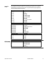
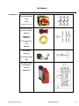
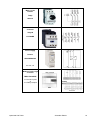
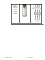
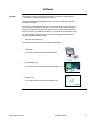
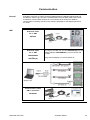
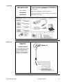
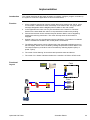
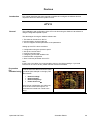
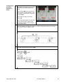
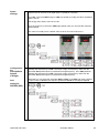
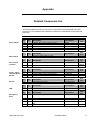
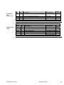
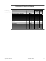
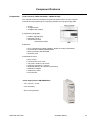
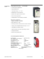
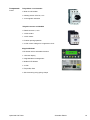
This document is based on European standards and is not valid for use in U.S.A. Compact / Hardwired / Logic Controller / Twido EIO0000000274 System User Guide MAR 2010 Contents Important Information.................................................................................................................2 Before You Begin....................................................................................................................3 Introduction .................................................................................................................................5 Abbreviations ..........................................................................................................................6 Glossary..................................................................................................................................7 Application Source Code ........................................................................................................8 Typical Applications ...................................................................................................................9 System .......................................................................................................................................10 Architecture...........................................................................................................................10 Installation.............................................................................................................................13 Hardware ...........................................................................................................................................................15 Software ............................................................................................................................................................19 Communication .................................................................................................................................................20 Implementation .....................................................................................................................22 Communication.....................................................................................................................23 Controller ...........................................................................................................................................................24 HMI ....................................................................................................................................................................43 Devices..............................................................................................................................................................56 Appendix....................................................................................................................................71 Detailed Component List.......................................................................................................71 Component Protection Classes ............................................................................................73 Component Features ............................................................................................................74 Contact.......................................................................................................................................77 Optimized HW Twido Schneider Electric 1 Important Information NOTICE Read these instructions carefully, and look at the equipment to become familiar with the device before trying to install, operate, or maintain it. The following special messages may appear throughout this documentation or on the equipment to warn of potential hazards or to call attention to information that clarifies or simplifies a procedure. The addition of this symbol to a Danger or Warning safety label indicates that an electrical hazard exists, which will result in personal injury if the instructions are not followed. This is the safety alert symbol. It is used to alert you to potential personal injury hazards. Obey all safety messages that follow this symbol to avoid possible injury or death. DANGER DANGER indicates an imminently hazardous situation, which, if not avoided, will result in death or serious injury. WARNING WARNING indicates a potentially hazardous situation, which, if not avoided, can result in death, serious injury, or equipment damage. CAUTION CAUTION indicates a potentially hazardous situation, which, if not avoided, can result in injury or equipment damage. PLEASE Electrical equipment should be installed, operated, serviced, and maintained only by qualified personnel. No responsibility is assumed by Schneider Electric for any NOTE consequences arising out of the use of this material. A qualified person is one who has skills and knowledge related to the construction and operation of electrical equipment and the installation, and has received safety training to recognize and avoid the hazards involved © 2009 Schneider Electric. All Rights Reserved. Optimized HW Twido Schneider Electric 2 Before You Begin Do not use this product on machinery lacking effective point-of-operation guarding. Lack of effective point-ofoperation guarding on a machine can result in serious injury to the operator of that machine. WARNING UNGUARDED MACHINERY CAN CAUSE SERIOUS INJURY Do not use this software and related automation products on equipment which does not have point-of-operation protection. Do not reach into machine during operation. Failure to follow these instructions can cause death, serious injury or equipment damage. This automation equipment and related software is used to control a variety of industrial processes. The type or model of automation equipment suitable for each application will vary depending on factors such as the control function required, degree of protection required, production methods, unusual conditions, government regulations, etc. In some applications, more than one processor may be required, as when backup redundancy is needed. Only the user can be aware of all the conditions and factors present during setup, operation and maintenance of the machine; therefore, only the user can determine the automation equipment and the related safeties and interlocks which can be properly used. When selecting automation and control equipment and related software for a particular application, the user should refer to the applicable local and national standards and regulations. A “National Safety Council’s” Accident Prevention Manual also provides much useful information. In some applications, such as packaging machinery, additional operator protection such as point-of-operation guarding must be provided. This is necessary if the operator’s hands and other parts of the body are free to enter the pinch points or other hazardous areas and serious injury can occur. Software products by itself cannot protect an operator from injury. For this reason the software cannot be substituted for or take the place of point-ofoperation protection. Ensure that appropriate safeties and mechanical/electrical interlocks for point-of-operation protection have been installed and are operational before placing the equipment into service. All mechanical/electrical interlocks and safeties for point-of-operation protection must be coordinated with the related automation equipment and software programming. NOTE: Coordination of safeties and mechanical/electrical interlocks for point-of-operation protection is outside the scope of this document. START UP AND TEST Before using electrical control and automation equipment for regular operation after installation, the system should be given a start up test by qualified personnel to verify correct operation of the equipment. It is important that arrangements for such a check be made and that enough time is allowed to perform complete and satisfactory testing. Optimized HW Twido Schneider Electric 3 CAUTION EQUIPMENT OPERATION HAZARD Verify that all installation and set up procedures have been completed. Before operational tests are performed, remove all blocks or other temporary holding means used for shipment from all component devices. Remove tools, meters and debris from equipment. Failure to follow these instructions can result in injury or equipment damage. Follow all start up tests recommended in the equipment documentation. Store all equipment documentation for future reference. Software testing must be done in both simulated and real environments. Verify that the completed system is free from all short circuits and grounds, except those grounds installed according to local regulations (according to the National Electrical Code in the U.S.A, for instance). If high-potential voltage testing is necessary, follow recommendations in equipment documentation to prevent accidental equipment damage. Before energizing equipment: • Remove tools, meters, and debris from equipment. • Close the equipment enclosure door. • Remove ground from incoming power lines. • Perform all start-up tests recommended by the manufacturer. OPERATION AND ADJUSTMENTS The following precautions are from NEMA Standards Publication ICS 7.1-1995 (English version prevails): Regardless of the care exercised in the design and manufacture of equipment or in the selection and rating of components, there are hazards that can be encountered if such equipment is improperly operated. It is sometimes possible to misadjust the equipment and thus produce unsatisfactory or unsafe operation. Always use the manufacturer’s instructions as a guide for functional adjustments. Personnel who have access to these adjustments should be familiar with the equipment manufacturer’s instructions and the machinery used with the electrical equipment. Only those operational adjustments actually required by the operator should be accessible to the operator. Access to other controls should be restricted to prevent unauthorized changes in operating characteristics. WARNING UNEXPECTED EQUIPMENT OPERATION Only use software tools approved by Schneider Electric for use with this equipment. Update your application program every time you change the physical hardware configuration. Failure to follow these instructions can cause death, serious injury or equipment damage. Optimized HW Twido Schneider Electric 4 Introduction Introduction This document is intended to provide a quick introduction to the described system. It is not intended to replace any specific product documentation, nor any of your own design documentation. On the contrary, it offers additional information to the product documentation, for installing, configuring and implementing the system. The architecture described in this document is not a specific product in the normal commercial sense. It describes an example of how Schneider-Electric and third-party components may be integrated to fulfil an industrial application. A detailed functional description or the specification for a specific user application is not part of this document. Nevertheless, the document outlines some typical applications where the system might be implemented. The architecture described in this document has been fully tested in our laboratories using all the specific references you will find in the component list near the end of this document. Of course, your specific application requirements may be different and will require additional and/or different components. In this case, you will have to adapt the information provided in this document to your particular needs. To do so, you will need to consult the specific product documentation of the components that you are substituting in this architecture. Pay particular attention in conforming to any safety information, different electrical requirements and normative standards that would apply to your adaptation. It should be noted that there are some major components in the architecture described in this document that cannot be substituted without completely invalidating the architecture, descriptions, instructions, wiring diagrams and compatibility between the various software and hardware components specified herein. You must be aware of the consequences of component substitution in the architecture described in this document as substitutions may impair the compatibility and interoperability of software and hardware. Optimized HW Twido Schneider Electric 5 Abbreviations Abbreviation AC CB DI DO DC E-STOP HMI I/O IL LD PC PS RPM SE TVDA VSD WxHxD Optimized HW Twido Signification Alternating Current Circuit Breaker Digital Input Digital Output Direct Current Emergency Stop Human Machine Interface Input/Output Instruction List - a textual IEC-61131 programming language Ladder Diagram – a graphic IEC-61131 programming language Personal Computer Power Supply Revolutions Per Minute Schneider Electric Tested, Validated, Documented Architectures Variable Speed Drive Dimensions : Width, Height and Depth Schneider Electric 6 Glossary Expression Altivar (ATV) Harmony Magelis MB - SL Modbus OsiSense Phaseo Preventa SoMove Lite TeSysU Twido TwidoSuite Vijeo Designer Lite Optimized HW Twido Signification SE product name for a family of VSDs SE product name for a family of switches and indicators SE product name for a family of HMI-Devices SE name for a serial Modbus communications protocol A Communications protocol SE product name for a family of sensors SE product name for a family of power supplies SE product name for a family of safety devices An SE software product for configuring drives SE product name for motor starters SE product name of a basic range family of PLCs SE product name for a PLC programming software An SE software product for programming Magelis HMI devices Schneider Electric 7 Application Source Code Introduction Examples of the source code and wiring diagrams used through out this document can be downloaded from our website. The example source code is in the form of configuration, application and import files. Use the appropriate software tool to either open or import the files. Extension CSV DOC DOP PDF PSX SPA XPR Z13 Optimized HW Twido File Type Comma Separated Values, Spreadsheet Document file Project File Portable Document Format - document Project file Schneider Product Archive Project file Project file Software Tool Required MS Excel Microsoft Word Vijeo Designer Lite Adobe Acrobat SoMove (Lite) TwidoSuite TwidoSuite EPLAN Schneider Electric 8 Typical Applications Introduction Here you will find a list of the typical applications and their market segments, where this system or subsystem can be applied: Packaging Recycling machines Textile Clothing machines HVac-R Heating and air conditioning systems Refrigerated display Commercial equipment Automatic washing Ticket vending machines Automatic dispensers Displays scrolling Advertising panels Ice-makers Building / services Automated systems for access and entry control (Door, awning, roller blind..) Other Machines Optimized HW Twido Wood working machines Solar energy management Agricultural and fish-farming machinery Ovens and incubators Swimming pools Schneider Electric 9 System Introduction This chapter describes the architecture, dimensions, quantities, required software, and the different types of components used within this system. Architecture General The control section of this application consists of a Twido controller, which can be controlled via push buttons or a Magelis operator panel. The load section is implemented using an Altivar VSD, which controls the speed and the direction of the motor. For functional safety, an optional Emergency Stop switch is used to initiate a shut down. The Emergency Stop switch activates a Preventa safety module and interrupts the 24 Vdc supply to the contactor which deenergizes the drive. The system also has two limit switches, which limit the motor’s path of travel. An additional sensor, which can be used to implement approximate position control via the pulse rate, can be included as an option. Layout Optimized HW Twido Schneider Electric 10 Components Hardware: Vario disconnect switch VCF (with red and yellow knob) Motor circuit breaker GV2L TeSysD Contactor LC1D Altivar variable speed drive ATV12 Harmony XALK Emergency-Stop switch with rotation release Phaseo power supply unit ABL8 Modicon Twido Compact Logic controller Magelis XBT-N HMI compact operator terminal XBT-N Harmony selector switches, push buttons and indicator lamps, XB5 OsiSense roller limit switches XCK Preventa safety module XPS Multi 9 circuit breaker Standard AC motor Software: TwidoSuite 2.20.10 SoMove Lite 1.0.20.0 Vijeo Designer Lite 1.2 Quantities of Components For a complete and detailed list of components, the quantities required and the order numbers, please refer to the Detailed Components List in the Appendix. Degree of Protection Not all the components in this configuration are designed to withstand the same environmental conditions. Some components may need additional protection, in the form of housings, depending on the environment in which you intend to use them. For environmental details of the individual components please refer to the list in the appendix of this document and the appropriate user manual. Cabinet Technical Data Input Mains voltage Power requirement Cable Size Cable Connection 400 Vac ~ 2 kW 5 x 2.5 mm² (L1, L2, L3, N, PE) 3 phase + Neutral + Ground Neutral is needed for 230 Vac (Phase and Neutral) Output Motor power ratings 1 asynchronous motors (4 poles:1500 RPM) controlled by ATV12 (0.37 kW) Functional Safety Notice (EN ISO13849-1 EN IEC62061) The standard and level of functional safety you apply to your application is determined by your system design and the overall extent to which your system may be a hazard to people and machinery. As there are no moving mechanical parts in this application example, category 1 (according to EN13849-1) has been selected as an optional safety level. Whether or not this functional safety category should be applied to your system should be ascertained with a proper risk analysis. This document is not comprehensive for any systems using the given architecture and does not absolve users of their duty to uphold the functional safety requirements with respect to the equipment used in their systems or of compliance with either national or international safety laws and regulations Emergency Stop Emergency Stop/Emergency Disconnection function This function for stopping in an emergency is a protective measure which complements the safety functions for the safeguarding of hazardous zones according to prEN ISO 12100-2. Optimized HW Twido Schneider Electric 11 Dimensions The compact dimensions of the devices used, for example, the controller and power supply, mean that the components can be installed inside a small control panel with the following external dimensions: 600 x 600 x 300 mm (WxHxD). The display elements used to indicate “Plant running” and “Safety Acknowledged” can be built into the door of the control cabinet along with the system master switch and Emergency Stop switch. Optimized HW Twido Schneider Electric 12 Installation Introduction This chapter describes the steps necessary to set up the hardware and configure the software required to fulfill the described function of the application. Assembly Notes The components designed for installation in a control cabinet, that is, Twido controller, Phaseo power supply unit, Harmony Emergency Stop button, line circuit breaker, contactors and motor circuit breaker, can be snapped onto a 35 mm DIN rail. The Altivar 12 variable speed drive is installed directly on the mounting plate. The Emergency Stop and master switches are installed in the cabinet door. There are two options available for mounting Harmony XB5 push buttons and indicator lamps: 1. Using a 22 mm hole drilled into the front door of the control cabinet in the appropriate position. 2. Using XALD housing, this can house up to 5 push buttons or indicator lamps. This XALD is designed for backplane assembly or direct wall mounting. 230 Vac wiring between disconnect switch, motor circuit breaker, load relay and variable speed drive. 24 Vdc wiring between power supply unit, Twido, push buttons, indicator lamps and variable speed drive control circuit. 24 Vdc between Emergency Stop, Preventa, and the control circuit of the load contactor. Optimized HW Twido Schneider Electric 13 Controller wiring ATV12 control circuit wiring The components and I/O points listed below represent a cross-section of the components and signals that are a basic necessity for control and display purposes and a number of optional inputs and outputs that can be used in conjunction with most typical applications (functional safety/maintenance switches). Twido inputs DC In 0 DC In 1 DC In 2 DC In 3 DC In 4 DC In 5 DC In 6 DC In 7 DC In 8 DC In 9 DC In 10 DC In 11 DC In 12 DC In 13 Description Forward Stop Reverse --Reserved---Reserved-Limit switch forward Limit switch reverse Motor circuit breaker Motor alarm --Reserved-Plant ready for Operation --Reserved---Reserved---Reserved-- Twido outputs Relay Out Q0 Relay Out Q1 Relay Out Q2 Relay Out Q3 Relay Out Q4 Relay Out Q5 Relay Out Q6 Relay Out Q7 Relay Out Q8 Relay Out Q9 Description Moving active --Reserved-Emergency Stop activated General alarm Motor forward Motor reverse Speed 2 Speed 3 Moving forward Moving reverse Twido 24 V supply Com Com 0 Com 1 Com 2 Com 3 Description Supply inputs 24 Vdc+24 Vdc +24 Vdc +24 Vdc +24 Vdc ATV12 LI1 LI2 LI3 LI4 RA RC Description Twido relay Out Q4 Twido relay Out Q5 Twido relay Out Q6 Twido relay Out Q7 +24 Vdc Twido dc In 8 Optimized HW Twido Schneider Electric 14 Hardware Components Disconnect Switch Vario VCD0 (red/yellow lever) Emergency Stop for door mounting Harmony XB5AS844 + XB5AZ141 Including Emergency Stop Label ZBY8330 Push Button Harmony with indicator lamp XB5 Emergency Stop Safety Module Preventa XPSAC5121 Optimized HW Twido Schneider Electric 15 Motor circuit breaker TeSys GV2L16 Contactor TeSysD LC1D09BD Power supply Phaseo ABL8REM24030 24 Vdc, 3 A Input: Modicon Twido Logic controller TWDLCDA24DRF 14 x 24 Vdc Inputs & 10 x Relay Outputs Optimized HW Twido Output: Schneider Electric 16 Operator Terminal Magelis XBTN401 Limit switch OsiSense XCKP2118P16 Variable speed drive Altivar 12 ATV12H037M2 1-phase, 230 Vac 0.37 kW Tower Light Harmony XVBL1B5 Optimized HW Twido Schneider Electric 17 Option: Motor starter (alternative) TeSysU LU2B12BL & LUCA05BL Optimized HW Twido Schneider Electric 18 Software General TwidoSuite is used for programming the Twido, including the configuration for communication and assigning inputs and outputs. The HMI application on the Magelis operator terminal is configured using VijeoDesigner Lite software. The Altivar 12 variable speed drive can be configured using the front operator’s panel. However, the SoMove software is a more user-friendly option and can be used for configuring the drive, saving data and quickly restoring existing data for service purposes. The software also allows you to optimize the parameters online. To use the software packages, your PC must have the appropriate Microsoft Windows operating system installed: Windows XP Professional The software tools have the following default install paths: TwidoSuite C:\Program Files\Schneider Electric\TwidoSuite Vijeo-Designer Lite C:\Program Files\Schneider Electric\Vijeo-Designer Lite SoMove Lite C:\Program Files\Schneider Electric\SoMove Lite Optimized HW Twido Schneider Electric 19 Communication General A Modbus connection is used to exchange data between the Magelis HMI terminal and the Modicon Twido Logic controller. The XBTZ9680 communication cable shown below is needed to connect these two devices. The software driver required for Modbus communication is already included in the software packages for the Magelis panel and the Twido. HMI Download Cable PC <> HMI XBTZ915 Download Cable PC <> HMI TSXCUSB485 + XBTZ925 (B) To program the HMI, use the cable XBTZ925 (B) with the RS845 Adapters TSXCUSB485 to connect the PC with the HMI. Verify that the adapter is in switch position 2. Communication Cable HMI <> Controller XBTZ9680 Optimized HW Twido Schneider Electric 20 Controller Communication Cable With USB Connector To program the Twido, use the cable TSXCRJMD25 with the RS845 Adapters (TSXCUSB485) to connect the PC with the Twido. PC <> Twido Verify that the adapter is in switch position 2. TSXCRJMD25 + TSXCUSB485 For the communication to work properly, port 1 must be configured on the Twido. Altivar 12 Cable set for SoMove Lite TSCMCNAM3M002P Use the USB to RJ45 cable to connect the PC (with SoMove installed) to the Altivar 12. Use the adapter as shown in the diagram. Optimized HW Twido Schneider Electric 21 Implementation Introduction Function This chapter describes all the steps necessary to initialize, configure, program, and start-up the system to achieve the application functions as listed below. 1. All the conditions required to clear the system alarm lamp must be met, that is, motor circuit breaker, maintenance switch and safety circuit must be ON. The group alarm message disappears and the Magelis panel is visible on the main screen. 2. In this application the motor can only be controlled in the “Forward” or ”Reverse” direction if the associated limit switch is not pressed and no alarms are pending. 3. Forward and reverse can be activated via push buttons. Motion can be stopped by pressing the red stop push button. The motor will stop when the limit switch is engaged. 4. Speeds 2 and 3 can only be selected using the HMI device. The selection is retained until it is modified via the HMI or the control panel is switched off. 5. The different HMI screens can be selected using the yellow/black left/right arrows on the text display. Motion can be invoked by setting the parameter FWD or REV to one. The output frequency of the drive can be increased by selecting Speed 2 (SP2) or speed 3 (SP3). 6. The screen “Drive Warning” shows the actual operation status and alarms. 7. The screen “PLC Status” indicates whether the controller is in RUN or STOP mode. Functional Layout Field Modbus/ RS485 Field Optimized HW Twido Schneider Electric 22 Communication Introduction This chapter describes the data passed via the communications bus (for example, Modbus RTU) that is not bound directly with digital or analog hardware. The list contains: Device Links The device links Direction of data flow Symbolic name Bus address of the device concerned. This application uses Modbus RTU via RS485 interfaces. The follwing devices are connected via Modbus: - Magelis HMI XBT-N401 as Master Twido as Slave 1 Datalink Twido<->HMI Device 1 XBTN401 (ModBus-Master 0) Address Designation %M3 Forward %M4 Reverse %M5 Speed 2 %M6 Speed 3 Device 2 Twido (ModBus-Slave 1) Address Name %M3 DRV_LEFT_HMI %M4 DRV_RIGHT_HMI %M5 SPEED_2_HMI %M6 SPEED_3_HMI Datalink Twido->HMI Device 1 XBTN401 (ModBus-Master 0) Address Designation %M8 Forward switch %M9 Reverse switch %MW7 Drive status %MW1 PLC status %MW10 Drive alarm Device 2 Twido (ModBus-Slave 1) Address Name %M8 HMI_DRV_DOWN %M9 HMI_DRV_UP %MW7 HMI_DRV Optimized HW Twido Schneider Electric 23 Controller Introduction This chapter describes the steps required for the initialization and configuration and the source program required to fulfill the functions. The controller program is created with TwidoSuite. Requirements To be able to use TwidoSuite and program the the controller you will need to verify that: Procedure Create a New Project TwidoSuite is installed on your PC The example application for this system, TwidoSuite project Example.xpr, is in the standard project directory (C:\Program Files\Schneider Electric\TwidoSuite\My Projects) The Twido is switched on The Twido is connected to the PC using the programming cable Setting up the Twido is done as follows: Create a New Project Configure the Twido Create Variables Create an Application Program Open an existing project Download the Program to the Twido Save the Program to Memory Card Program Duplication with Memory Card 1 To create a new project click on the arrow next to ’’Programming’’ Mode 2 Select the Project tab and click on: Create a new project Optimized HW Twido Schneider Electric 24 3 Input the project information as required: Project name Directory path for save Author Department Index Industrial Property Continue with Create Configure the Twido 1 To configure the hardware, the communication parameters and the bus system, click on the Describe tab. 2 In the Catalog on the right select the Twido type: Bases-> Compact-> TWDLCDA24DRF Click on Place to see the Twido show up in the rack image. 3 Again in the Catalog, for the communications module select: Serial Adapter-> TWDNAC485D Click on Place to see the adapter show up in the rack image Optimized HW Twido Schneider Electric 25 4 To configure the communications port, right mouse click on the RS485-Port in the graphical image and select Configuration… in the pop-up menu. 5 You can leave the default values as they are and accept them by clicking on OK. Default: Protocol Type: Modbus Address: 1 6 The Twido is now configured. In the yellow field above the Twido image you can enter a name. The name Example was given for this application. Optimized HW Twido Schneider Electric 26 7 To complete the configuration add the Magelis HMI. In the Catalog select: Network Elements-> Modbus Elements-> Magelis 8 A right mouse click on the Magelis opens up a pop-up menu. Select: Configuration… 9 In the Configuration dialog give the device a Name (for example, XBTN401). Protocol Type: Modbus Address: Master Confirm the changes with OK. Optimized HW Twido Schneider Electric 27 10 Move the mouse over the Magelis image until the mouse pointer changes to the connection pointer (a white cross). Click with the mouse and pull a connection across to the Modbus port of the Twido. The connection is displayed as a line when you let go of the mouse button. A double click on the My network 1 field opens a configuration dialog. 11 Input the following parameter values: Baudrate: 19200 Data Bits: 8(RTU) Parity: none Stop Bit: 1 Confirm with OK. Create Variables 1 Optimized HW Twido Change to the Program tab. Schneider Electric 28 2 Define the required inputs (%I0.x) and outputs (%Q0.x) in the table Click on Apply to take on the changes. 3 Switch to the tab Configure and the sub group Configure the Data to define the variables used in the program. 4 Use this editor to define the internal program variables and variables transferred between the HMI and Twido. Use the Object Categories on the left to define different types of variables. Optimized HW Twido Schneider Electric 29 5 Optimized HW Twido Use the Save icon at the bottom of the window to save the program. Schneider Electric 30 Create a Program 1 Use the Edit Program function to invoke the program editor. LADDER is the default programming language Once the first rung has been completed and analyzed, the program can be viewed and programmed in LIST mode. 2 Start the programming by clicking on the add a section icon. This will create a section with empty rungs. 3 Clicking on the rung changes its color and indicates the current rung is being edited. Clicking on an icon in the toolbar inserts the selected object at the first available place on the rung. Drag and dropping the elements is also supported. 4 Click on the top of a rung to add a rung header or comment. 5 You can also add a section header. Optimized HW Twido \ Schneider Electric 31 6 Add Coils … 7 ..or Compare blocks, Function blocks, Timer or Counter .. 8 To add more sections, use: Add a section. 9 Note: a section can be added either at the end of the current program or in between existing sections of the current program. The editor automatically recognizes whether a rung is syntactically complete and marks it in yellow. The rung, however, has not yet been analyzed. The Analyze program button is in the bottom right hand corner. 10 If the analysis is successful, the yellow band changes to green. Rungs with syntax errors are indicated in red. Syntax errors are listed at the bottom of the edit field. The error field can be enlarged by clicking on the button to the left of the box. Optimized HW Twido Schneider Electric 32 11 Here is the enlarged window. To leave the window just click on the screen outside the frame. Once the program has been successfully analyzed you can download it to the Twido. Open an existing Project 1 To open a project use the Open an existing project function in the Project menu. In the open an existing project window select the medium : Disk or Controller Give the file Format (for a project file: TwidoSuite Project), select the folder and select the file you wish to open. Select the project Example and click on Open to open the project. Download to the Twido 1 Optimized HW Twido Click on the tab Program in the main menu Schneider Electric 33 2 Select Debug in the sub-menu (upper right) to obtain access to the connect selection. 3 In the sub-menu select the Connect tab (right side). Then the available communication ports are shown. Check that the the USB communication cable is connected, and select USB. 4 5 Continue with OK. A progress bar is visible while TwidoSuite establishes the connection. After successfully connecting to the Twido, TwidoSuite compares the status of the project and the Twido. The lower section displays the type of exchange. Select: Transfer PC ==> controller and click on OK. 6 If the Twido is already running it must be stopped first. Confirm with OK if you wish to proceed. Optimized HW Twido Schneider Electric 34 7 You are notified that the contents of the Twido are about to be over-written. Confirm with OK to continue. 8 The download condition is indicated with a progress bar. 9 After a successful download, TwidoSuite switches automatically to the online viewing. 10 A control panel appears in the foreground. Here you can start and stop the Twido. The upper button enlarges the control panel, offering more Twido status information. 11 If you start the Twido you will be asked to confirm the action. If you wish to start the Twido click on OK. Optimized HW Twido Schneider Electric 35 12 After successfully starting the Twido, the RUN indicator changes from yellow to green. Optimized HW Twido Schneider Electric 36 Download Firmware 1 Ensure you have connected the Twido with the USB cable. Select: PLC firmware update 2 You are notified that the firmware download will delete any program running on the Twido. Continue by clicking Next >. 3 Select the type of connection. (for example, COM1, COM2, USB) In this case select USB. Select the file to be downloaded with Browse… . Click on Next > to continue. Optimized HW Twido Schneider Electric 37 4 A comparison of the hardware and existing firmware is shown, as well as the controller state. If the controller is in the running state, it must be stopped before the firmware can be updated. Click on Stop Controller. 5 Confirm the stop with Yes. 6 The new Twido status is displayed in File and Device Properties (green tick in Stopped). Continue with Next >. Note: Updating the executive of your controller will delete the current control application from the controller Memory. You will have to reload the program after updating the controller. 7 Optimized HW Twido Confirm the notification not to interrupt the download with Yes Schneider Electric 38 8 A progress bar is displayed. 9 A message confirms the successful download and asks if you wish to download more. Click on No if you are finished. 10 In the progress dialog click on Close. 11 Click on Yes to exit the loader. Optimized HW Twido Schneider Electric 39 Save the Program to Memory Card 1 To store the program use the 32 kByte EEPROM memory card: TWDXCPMFK32 Remember to turn off the power to the Twido when removing or replacing the memory card. 2 Connect to the Twido (via Debug tab and Connect USB). 3 Select Animate the program and click on Check PLC. Optimized HW Twido Schneider Electric 40 4 Select: See memory information and click on Save. 5 If the Twido is running, click on OK to stop it. 6 If you wish to restart the controller after storing the program on the memory card click Yes. 7 Once the Twido is running again, the save sequence is finished. You can now remove the memory card and copy the program to other Twidos. Remember to switch off the Twido before removing the memory card. Optimized HW Twido Schneider Electric 41 Program Duplication with Memory Card 1 Turn off the Twido, remove the cover to the card connector and insert the memory card (make sure the card matches the Twido type and the hardware configuration is the same). 2 Turn the Twido on. The program transfer from EEPROM card to Twido EPROM begins automatically. When the transfer is complete the RUN-LED lights up. 3 Optimized HW Twido Turn the Twido off to remove the memory card. Replace the cover on the connection and switch the Twido back on. It starts to run automatically. Schneider Electric 42 HMI Introduction This application features a compact Magelis XBT-N401 4-line-text-display HMI, which is interfaced with the controller via the Modbus protocol. The Vijeo Designer Lite software is used to program and configure the terminal. The following pages explain this procedure. Requirements Before starting work with Vijeo Designer Lite the follwing conditions must be fulfilled: Procedure Create a new Configuration VIJEO-DESIGNER LITE is installed on your PC. The example project has been copied to the Vijeo Designer Lite project storage path (C:\Program Files\Schneider Electric\VIJEO-DESIGNER LITE\Apps). The Magelis HMI is switched on and connected to the PC with the cable XBTZ915. Setting up the HMI is done as follows: Create a new Configuration Create an Alarm Create an Application screen Creating Variables (Boolean, words, lists) Screen Navigation & Viewing System Pages Download Program to the HMI Driver-Manager: adding interfaces 1 In the menu bar in Vijeo Designer, select File->New Select Terminal Type XBTN401. Select Modbus as Terminal Protocol. Continue by clicking on Create. Optimized HW Twido Schneider Electric 43 2 The project browser on the left hand side of the tool lists the elements Configuration and Design. Configuration is used to set up the HMI parameters. Design offers a breakdown of display screens and alarm panels. 3 Under Terminal – XBT-N401-Control the user modus can be set up so that the operator uses either the function keys or the selector keys for control. Select the selector keys. Optimized HW Twido Schneider Electric 44 4 Under Protocol – Modbus input the Communication parameters: Transmission Speed: 19200 Parity Bit: Data Length: Stop bits: None 8 1 The default parameters given for Protocol Specific are retained. 5 Under Languages the default display language for the operator can be set. Use the Add button to add more languages so that the operator can select the language he wishes to use. Optimized HW Twido Schneider Electric 45 6 Under Equipment you can define the devices that communicate with the HMI. EQPT1 is the default Name, and may be changed. As Address insert the slave address. Use Add to add more slaves. Use Symbol Variables File to import a variable list from a Twido program. After clicking on Symbol Variable File the Open dialog is displayed. Select the appropriate controller variable list. Continue with Open. 7 The Communication Table defines the data structures used in communication for example, memory buffers, alarm lists, function key definition, communication control etc. Right mouse click on Communication Table and uncheck Disabled in the pop-up menu. 8 Optimized HW Twido Click on the corresponding table (for example, EQPT1 or whatever you named the equipment) Schneider Electric 46 9 The Function table indicates the activated functions for this equipment. To add more Functions click on the checkbox beside the function. It is then listed in the table on the right. The Base Address is the start address of the Dialog table. The data area of each function is shown in the table beneath. 10 Cycle defines the cycle time for updating the data. Use Security to define passwords to help protect the HMI from unauthorized use. You can define how long the authorized access lasts in minutes. The validity of the password levels, A, B, C is configurable for individual screens. Create an Alarm 1 Click on Alarms to open the alarm-list. The function is only available if it was activated in the function list (as shown above), 2 The left column shows the address (for example, %MW104). The row shows the individual bits for this memory word. Select a bit with a double click on the representative cell. Optimized HW Twido Schneider Electric 47 3 On the Alarm Settings tab, add the text to be displayed for this alarm in the Alarm Text box. Confirm with Enter. The text is displayed on the screen should an alarm of this type ocurr. The position of the text on the screen can be defined under Alarm Panel and viewed in the Panel Preview. 4 You can define the actions of the function keys under Static Function Keys (only available if you selected function key mode in the Terminal Configuration) The variables defined in the Function Setting are used by the function defined under Function Name to provide either impulse or toggle commands. You can also display screens or system information. Create an Application screen 1 Design HMI screens to display system variables using Application Panels entry. PANEL 1 is the default name for the first screen. Optimized HW Twido Schneider Electric 48 2 To create a new screen, select: Application Panels-> Add Panel 3 Click on the newly created screen name in the project browser to display the actual screen. The screen can now be designed. Add appropriate text for the screen. The Security Access is used to apply the password level required for this screen. Creating Variables 1 Boolean, Word, List For Alphanumerical Text variables (boolean or word) select the icon in the toolbar and position the text box on the screen. This box is used to display the value. The position and size can be changed later. Optimized HW Twido Schneider Electric 49 Click on the positioned Alphanumerical Text object to open up the attributes dialog. On the Alphanumerical Text – Settings tab, enter the address of a variable in the Variable field. 2 You can browse for a variable using the ‘…’ button at the end of the Variable field. Define the type of variable (%Mx, %MWx, etc.), the number (i:), and the Format (bit, word, etc.). If you have imported variables from other devices (in Equipment -> Symbol Variables File), a variable can be selected from the Symbol list for that device. Confirm with OK. 3 4 5 Use Display Type to define how the variable should be displayed. In the Conversion is it possible to enter a formula for processing the variable before the value is displayed. The settings of access requirements are on the Access Mode and Security tab. For an enumerated list select the icon in the toolbar and position the text box on the screen. This box is used to display the value. The position and size can be changed later. Optimized HW Twido Schneider Electric 50 6 7 Click on the positioned Enumerated List object to open up the attribute dialog. On the Enumerated List – Settings tab, input the Variable address and Font Size. Use the List Value tab to assign different display texts to the various variable values. The texts are displayed at run-time on the screen according to the variable’s actual value. If you selected more than one language texts have to be entered for each language. Screen Navigation & Viewing System Pages 1 For a navigation symbol select the icon in the toolbar and position the object on the screen. This symbol can be used to switch between the different HMI screens. The direction of the arrow corresponds to the arrow keys on the front of the HMI device. On the tab Link - Settings under Link Action select Access Application Panel and in Panel Selection, select the screen you wish to have displayed when the key is pressed. Optimized HW Twido Schneider Electric 51 Download Program To the HMI 1 With File->Open Open the example file Example.dop, stored in the path: C:\Program Files\Schneider Electric\VIJEO-DESIGNER LITE The application is opened and the screens are displayed. Verify that the HMI is connected to your PC with the cable XBT-Z915 or alternatively with the USB adapter TSXCUSB485 and the cable XBT-Z925 (B). 2 Use: Device->Download… to download the application to the HMI. 3 Select the languages you wish to download to the HMI. Continue with Download. 4 You are asked to overwrite any application already in the HMI. Continue with OK. Optimized HW Twido Schneider Electric 52 5 Note: If the communications driver cannot be activated, you will have to change the set up in the Driver Manager - see the Driver Manager section for this procedure. 6 The transfer is started. 7 A progress bar is displayed. 8 You are informed that the transfer is successfully completed. Continue with OK. Optimized HW Twido Schneider Electric 53 1 Driver-Manager Adding interfaces The Drive-Manager is a separate tool used to set up the communications drivers. Start the tool in Windows with: Start->All Programs-> Schneider Electric -> Communication Drivers -> Driver Manager and go to the UNITELWAY Driver tab. 2 Click on Configuration. 3 A list of available interfaces is diplayed for example, COM5 For the serial interface with the XBTZ915 cable, you have to add COM1. Click on Add Station… Optimized HW Twido Schneider Electric 54 4 Select COM1 as COM Port. For the Station ID, enter HMI. Close the dialog with OK. 5 The second interface is now visible. Close the dialog with OK. 6 The drivers are reset and initialized. 7 The reset is confirmed. Continue with OK. Optimized HW Twido Schneider Electric 55 Devices Introduction This chapter describes the steps required to initialize and configure the different devices required to attain the described system function. ATV12 General The initialization and configuration of the ATV12 is done using the SoMove Lite software or using the integrated operator’s panel. The advantages of using the SoMove software are: The data can be stored on the PC Documentation can be printed and The tool supports online optimization of the parameters. Setting up the ATV is done as follows: Configuration using the operator’s panel Set up the Low Set Point Input the nominal power Configuring ATV12 with SoMove Lite Download the configuration Store customer parameter set on ATV Note: If this is not a new drive it is recommended to return to the factory settings. If you need instructions on how to do this, please read the drive documentation. To speed up the commissioning, first make Preparation a note of the motor data found on the motor For Commissioning type labels (see example on the right) This data includes: Nominal voltage Nominal power Nominal frequency Power factor cos At the time of configuration, the VSD must not be under Twido control (that is, no commands are issued from Twido to the drive). Optimized HW Twido Motor name plate Schneider Electric 56 Configuration using the Operator’s Panel 1 On first start-up of the VSD the display shows bFr and indicates that the basic frequency of the motor needs to be input. Press the key ENT and, using the jog dial, input the nominal frequency. The input range is 50 to 60 Hz. Confirm the input with ENT. Now restart the VSD. The screen shows rdy. 2 3 Optimized HW Twido The menus shown here are only those that are required to be used for this architecture. See the ATV12 manual for a full description. The display shows rdy, from here you can jump to the rEF, MOn and COnF – mode by pressing mode and turning the jog dial. To change configuration settings you always have to go through the COnF -mode. To access the CoS – menu for setting the cos phi – parameter, first you have to switch from nPr (nominal power rating) to COS. Schneider Electric 57 Input the nominal motor values 4 Go to the menu drC (Drive control) and setup the drive parameters as written on the motor type label. These are: CoS – Rated motor cos phi UnS – Rated motor voltage nCr – Rated motor current FrS – Rated motor frequency nSP – Rated motor speed The parameter UnS, is the nominal voltage of the motor (factory setting: 230 Vac). Single phase drives accept a maximum of the mains voltage, so that here the value can only be reduced. Note that motors with a nominal voltage of 230/400 Vac require a delta connection. The parameter FrS is the nominal frequency of the motor and can usually be left at the default value of 50Hz. In the following picture you can see the default values. Optimized HW Twido Schneider Electric 58 Thermal current setting 5 Current limitation 6 Go to ItH press the ENT key and input the nominal power value using the jog dial. The default value is 1.1 Amps. Confirm the input with ENT. Optimized HW Twido In the menu CLI you can define the maximum allowed current for the motor. This value should be higher than the nominal power rating to allow a certain amount of overload. (for example, CLI = 1.25 * nCr). Schneider Electric 59 Speed settings 7 SPL (Speed limit menu) is the menu for the target frequency of the drive when a 24 Vdc signal is input to the ATV12 via digital input LI1 (FWD) or LI2 (REV). Go to SPL. Now press ENT and go to LSP (Low speed) to modify the value, the default value is 0.0 Hz. Use the jog dial to input a value of 35.0 Hz. Go to the next entry in the menu, HSP (High speed). Here you can input the maximum allowed speed. This value is normally set to a default value of 50 Hz and can be left as it is. Configuration for PS2=SetPoint Speed2 (LI3High) 8 And Go to the menu PSS (Preset speed menu). Now press ENT and go to PS2 (SetPoint Speed2) and select the Input L3H. If this Input is high, the frequency value from the parameter SP2 (Preset speed 2) is selected as target frequency. Go to PS4 (SetPoint Speed4) and select the Input L4H. If this Input is high, the frequency value from the parameter SP3 (Preset speed 3) is selected as target frequency. Afterwards you can select the parameter SP2 and SP3. Press ENT and use the jog dial to input a value of 35 Hz for the setpoint Speed2 and 50 Hz for the setpoint Speed3. setting for SPEED2 (SP2) Optimized HW Twido Schneider Electric 60 In the menu I_O you can define options regarding the In- and Outputs of the ATV12. Go to tCC and leave the setting on 2C which means that the ATV12 can be driven by 2 wires. Then enter to tCt and check if it is set to trn (Transition mode). I/O-settings 9 I/O setting for RRS = Reverse (LI2High) 10 In the menu FUn you can define application functions of the ATV12. Go to rrS (Reverse) and select the Input LI2High. If this Input is high, the drive runs in Reverse-mode. Optimized HW Twido Schneider Electric 61 Configuring ATV12 with SoMove Lite 1 After starting SoMove Lite you will see the window as shown here on the right – the version is automatically shown in english. 2 To create a new Project, select Create a Project OFF-line and choose the desired device. Continue with Next. 3 In the Device dialog, select a Reference-Type and the Firmware Version. In this example: Reference: ATV12H037M2 Version: V1.1IE01 The Version defines a set of functions. Additional information displayed: - Supply Voltage - Nominal Power - Nominal Current - Max Transient Current of the VSD. Continue with Create. Optimized HW Twido Schneider Electric 62 4 To save the project use File–>Save as… Insert the File name (here ATV12) and continue with Save 5 Select: Communication->Edit Connection to go to the connection dialog. 6 Optimized HW Twido Select Advanced to check and edit the connection settings. Schneider Electric 63 7 Select the appropriate COM Port, here COM1 is used. Baud Rate: 19200 Parity: Even Stop Bits: 1 You can also perform a test of the connection by clicking on Test Continue with OK. 8 You can also perform a test of the connection by clicking on Test. Continue with OK. 9 The Main-Window of SoMove consists of four tabs. The tab, MyDevice, includes the basic information about the device. 10 The tab, Parameters, shows a table of all adjustable parameters. Optimized HW Twido Schneider Electric 64 11 The tab, Fault Detection, shows the current current detected faults. 12 The tab Monitoring, is used to monitor the parameter values of the VSD. Click on the parameter to be observed and then click again on the plane on the right hand side. 13 On the Parameters tab, select MOTOR CONTROL. Leave the value for BFR at 50Hz. Insert your motor values as found on the name plate of the motor. Optimized HW Twido Schneider Electric 65 14 Select: FAULT MANAGEMENT MOTOR THERMAL PROT. Modify ITH according to the values for your motor. 15 Select: Application Funct. Set the Input for RRS to LI2 high RAMP Change ACC & DEC to 0.1s PRESET SPEEDS Set the Input for PS2 (2 preset speeds assign.) -> LI3 high and LI4 high. The Preset speeds can be chosen by setting the appropriate inputs of the drive. Change SP2 (Preset Speed 2) to 35Hz and SP3 (Preset Speed 2) to 50Hz. SPEED LOOP Set LSP (Low Speed) to 5 Hz 16 Select: INPUTS / OUTPUTS CFG Set TCC to 2 wire. Set TCT to Transition. Optimized HW Twido Schneider Electric 66 17 Select: File-> Save or use the icon in the toolbar, to save your configuration. 1 Download the Configuration Check that the PC is connected to the Altivar drive. For this use the cable set TSCMCNAM3M002P. 2 To download the configuration to the drive click on icon in the toolbar: Store Values to Device Optimized HW Twido Schneider Electric 67 3 Before proceeding read the notification carefully. If you agree to follow these instructions, press Alt+F. Connect to Device / Upload the Configuration 4 A progress bar is displayed during the download. 1 To connect to the device click the Connect to Device icon in the toolbar Or select: Communication->Connect to Device 2 To upload the configuration to the PC answer the question that follows with YES The configuration in the PC-File will be overwritten! Optimized HW Twido Schneider Electric 68 3 You can also upload the configuration from the device into PC by clicking on the Load Values from Device icon And answer the question with YES HMI Personalization 4 A progress bar is displayed during the upload. 1 With SoMove you can configure the main menu of your ATV to make the navigation easier Select: Device->ATV12 HMI Personalization 2 Tab: MyMenu Here you can customize the main menu of the ATV12 by selecting the items to be shown. 3 Tab: Visibility Here you can select the most common parameters which should be shown in the ATV12 HMI Optimized HW Twido Schneider Electric 69 Store current configuration on ATV12 1 To permanently store the downloaded configuration into the drive, select: Configuration -> Store current configuration You are asked to store the current configuration in the drive´s memory. Answer the question with Yes After the configuration has been stored a message is beeing displayed. Confirm with OK. Optimized HW Twido Schneider Electric 70 Appendix Detailed Component List The following tables provide a list of the main components for the Optimized HW Twido architecture. The complete bill of materials is included in the EPLAN file for the Optimized HW Twido. Hardware-Components Sarel cabinet Main switch PLC and I/O modules Drives , Servo Drives & Motor Starter Sensor HMI EmergencyStop Pos. Qty. Description Part Number 1.1 1.2 1.3 1.4 1.5 1 1 2 1 1 Cabinet, 800 x 600 x 400mm (Sarel) Fan filter, 230 Vac, 56 m³/h (Sarel) Filter unit for ventilation (Sarel) Thermostat for Fan, 0..60°C (Sarel) Phaseo Power supply 230 Vac / 24 Vdc 3 A 83344 87901 87911 87562 ABL8REM24030 Pos. Qty. Description Part Number 2.0 1 Disconnect switch Harmony Vario VCD0 Pos. Qty. Description Part Number 4.0 1 Twido controller Compact with 24 I/Os TWDLCDA24DRF 4.1 1 RS485 Interface adapter for Magelis HMI TWDNAC485D Pos. Qty. Description Part Number 5.0 5.1 5.2 1 1 1 ATV12 variable speed drive 0.37 kW TeSysU Base unit for two directions TeSysU Control unit ATV12H037M2 LU2B12BL LUCA05BL Pos. Qty. Description Part Number 6.0 2 OsiSense Limit switch XCKP2118P16 Pos. Qty. Description Part Number 7.0 1 HMI Magelis XBT-N XBTN401 Pos. Qty. Description Part Number 8.0 1 Preventa Emergency Stop safety module XPSAC5121 8.1 8.2 8.3 1 1 1 XB5AS844 GV2L16 GVAE11 8.4 1 Harmony Emergency Stop pushbutton TeSys Motor circuit breaker, 14 A Auxiliary contacts for circuit breaker 1 NO 1 NC Illuminated Push button 1NC, blue Rev/ Vers. Rev/ Vers. Rev/ Vers. FW4.20 Optimized HW Twido Rev/ Vers. Rev/ Vers. Rev/ Vers. Rev/ Vers. XB5AW36B5 Schneider Electric 71 Pushbutton and Tower Light Pos. Qty. Description Part Number 9.0 1 Harmony Box for 3 button XALD03 9.1 9.2 9.3 9.4 1 2 1 1 Harmony Signal lamp LED white Harmony Pushbutton with LED green Harmony Pushbutton with LED red Harmony Tower Light XB5AVB1 XB5AVB3 XB5AVB4 XVBL1B5 Rev/ Vers. Software-Components Software and cable Rev./ Vers. V2.20 Pos. Qty. Description Part Number 10.0 10.1 10.2 10.3 10.4 10.5 10.6 1 1 1 1 1 1 1 TwidoSuite Software USB programming adapter Communication cable Twido-HMI Vijeo Designer Lite Programming cable PC-HMI SoMove Lite Altivar-Set Connection cable for drives TWDBTFU10M TSXCUSB485 XBTZ9680 VJDSNDTMSV12M V1.2 XBTZ915 VW3A8200 Optimized HW Twido TSCMCNAM3M002P Schneider Electric 72 Component Protection Classes Cabinet Positioning Component IP54 Protection Class Harmony Emergency Stop switch Vario Disconnect Switch VCD0 TeSysD Contactor LC1D TeSys Motor Circuit breaker GV2L TeSysU Motor Starter Combination Altivar 12 variable speed drive Phaseo Power Supply ABL8 Harmony Emergency Stop switch XPSAC Twido controller Illuminated switches, series ”Harmony“ with housing Harmony Compact tower light XVB OsiSense limit switch XCK Filter and fan Fan thermostat Optimized HW Twido In Field, On Site IP65 X IP67 Front IP55 Inside IP65 X IP20 X X X X X X X X X IP66 X X IP40 X Schneider Electric 73 Component Features Components Twido controller (TWDLCDA24DRF+ TWDBTUF10EF) The controller used in this example comprises the power base of a Twido compact controller and a programming set comprising software and a programming cable 24 Vdc 14 digital inputs 10 digital relay outputs 3 programming languages: Ladder Language (LD) Instruction List (IL) Sequential Function Chart/Grafcet (SFC) Expansions: Up to 4 expansion modules (Fieldbus-, Digital- & Analog-I/O-Modules) Communication adapter RS232/RS485 Back-up function with EEPROM Real time clock Pre-defined functions: Drum control Fast Counters up to 5 kHz Very Fast counters up to 20 kHz Frequency measuring 1..20 kHz Reserved Memory for LIFO/FIFO-processing PWM-/PLS-Outputs External PLC-Start PID-controller Power Supply Phaseo ABL8RPS24030 - 100…240 Vac / 24 Vdc - 3.0 A secondary - Short circuit protected Optimized HW Twido Schneider Electric 74 Components Contd. Variable Speed Drive Altivar ATV12H037M2 0.37 kW, 230 Vac single phase Integrated EMC Filter Temperature Range: - 10..+ 50°C Speed range 1 to 20 (0.5..400 Hz) Speed control using Flow Vector Control Drive and motor protections Compact profile, In-row mounting on a DIN rail Motor starter combination TeSysU: LU2B12BL+ LUCA05BL Motor output up to 1.5 kW Reversing contactor control with elect. and mech. interlock Tripping current, adjustable within the range 1.25…5 A Trip feedback via auxiliary contacts Optional activation of a brake using auxiliary contacts Compact dimensions Minimum wiring requirements Preventa Safety Module: XPSAC5121 For monitoring Emergency Stop Max. category accord. EN13849-1 3 No. of safety circuits 3 N/O No. of additional circuits 1 Solid-State Indicators 2 LED Power supply AC/DC 24 V Response time on input opening < 100 ms AC-15 breaking capacity C300 DC-13 breaking capacity 24 V/2 A - L/R 50ms Minimum voltage and current 17 V/10 mA Dimensions (mm) 114 x 22.5 x 99 Connection Captive screw-clamp terminals Degree of protection IP20 (terminals) IP40 (casing) Optimized HW Twido Schneider Electric 75 Components Contd. TeSys Motor circuit breaker Motor circuit breaker Isolating switch: GV2L16, 14 A 33.5 magnetic activation TeSysD Contactor LC1D09BD Rated current 9 A, AC3 1x NO contact 1x NC contact Positive opening operation 24 Vdc control voltage incl. suppressor circuit Magelis XBTN401 LCD-Screen with 3 selectable functions 4 line text display Integrated alarm management Modbus RTU Master 24 Vdc Flat profile, IP65 Quick mounting using spring clamps Optimized HW Twido Schneider Electric 76 Contact Publisher Process & Machine Business OEM Application & Customer Satisfaction Schneider Electric Automation GmbH Steinheimer Strasse 117 D - 63500 Seligenstadt Germany Homepage http://www.schneider-electric.com/sites/corporate/en/home.page As standards, specifications and designs change from time to time, please ask for confirmation of the information given in this publication. Optimized HW Twido Schneider Electric 77