1
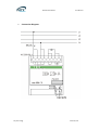
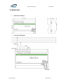
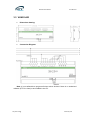
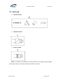
KNX Dimmer Module
User manual-Ver. 1
VKAD 0103
VKAD 0203
VKAD 0403
KNX Dimmer Module User Manual Content
1. 2. 3. 4. 5. 6. 7. Introduction ................................................................................................................... 3 Technical Parameter .................................................................................................... 3 Dimension and Connection Diagram ...................................................................... 5 3.1 KA/D0103.1 ............................................................................................................... 5 3.2 KA/D0203.1 ............................................................................................................... 7 3.3 KA/D0403.1 ............................................................................................................... 8 3.4 Load Type ................................................................................................................. 9 Dimming operation mode ......................................................................................... 10 Programming Introduction ...................................................................................... 10 5.1 Switch ...................................................................................................................... 10 5.2 Relative dimming .................................................................................................. 10 5.3 Absolute dimming ................................................................................................ 11 5.4 Status Report ......................................................................................................... 11 5.5 Scene ....................................................................................................................... 12 5.6 Preset Value ........................................................................................................... 12 5.7 Staircase Lighting Function ............................................................................... 12 5.8 Reset ........................................................................................................................ 13 5.9 Error Report ........................................................................................................... 13 5.10 Normal operation signs ................................................................................. 13 Parameters Setup Description ................................................................................ 13 6.1 Introduction ............................................................................................................ 13 6.1.1 Normal Dimming ................................................................................... 13 6.1.2 Staircase Lighting ................................................................................. 14 6.2 Parameter Window “Device general” .............................................................. 14 6.3 Parameter Window “CH X active” .................................................................... 15 6.4 Parameter Window “CHX general” .................................................................. 17 6.5 Parameter Window: dimming general ............................................................. 18 6.5.1 Setting of “CH X dimming general” ................................................. 18 6.5.2 Parameter Window “X: dimming” .................................................... 21 6.5.3 Parameter Window “X: scene page” ............................................... 24 6.5.4 Parameter Window “X: preset” ......................................................... 26 6.6 Staircase Lighting Mode ..................................................................................... 28 Communication Object Description ...................................................................... 30 7.1 Communication object of “Device General” ................................................. 30 7.2 General communication object of “Dimming Actuator” ............................. 31 7.3 Scene function communication object of “Dimming Actuator” ............... 32 7.4 Preset value function communication object “Dimming Actuator” ........ 32 7.5 Staircase Lighting Function communication object of “Dimming
Actuator” .............................................................................................................................. 33 Vity Technology www.vity.com KNX Dimmer Module User Manual 1. Introduction
The dimmer is a device dimming the luminaries directly by the data in the memory,
and the data is processed in advance in the programming software according to the
distribution characteristics of the luminaries’ brightness. The controller transfers the
brightness data value to output voltage to control the brightness of the luminaries; Our
dimmers have 3 categories: 1-channel, 2-channel and 4-channel. It is able to dim one
independent group of luminary by 1-channel dimmer, 2 independent groups of luminaries
by 2-channel dimmer, and 4 independent groups of luminaries by 4-channel dimmer,
Dimmer is also equipment which is installed in the distribution box or distribution
board and connected to the EIB BUS. It can be programmed; it can be use to customize
the rooms’ environment to build the various scenes, such as WATCH MOVIE,
ENTERTAMENT, DINNER and REST and so on; it’s brightness value can be set as any
value (1-100%); it is able to set the duration time to dim up or down to the target
brightness value and the gradual change speed to extend the luminaries life and save
energy and so on.
2. Technical Parameter
Power Supply: Operating voltage 21~30VDC, made available by the EIB-BUS
Input Voltage: 230VAC (50/60Hz)
Dimming Output: VKAD 0103----1 channel
VKAD 0203----2 channels
VKAD 0403----4 channels
KA/D Type: 01.03.1 / 02.03.1 / 04.03.1
Output Voltage: 230 V AC (50/60Hz)
Max. Output Capacity: VKAD 0103, 500W per out output
VKAD 0203, 500W per out output
VKAD 0403, 400W per out output
Max. Leakage Loss: 5W
BUS Connection: 1 KNX/EIB BUS connection terminal
Load Circuits: 2 connection terminals per output
Vity Technology www.vity.com KNX Dimmer Module User Manual Cable Cross-section: single core 0.2~4.0mm2
multi core 0.2~2.5 mm2
Operation Display: LED and push button for assigning the physical address
IP Grade: IP 20, EN 60 529
Temperature Range: Operation -5°C~45°C
Storage -25°C~55°C
Transport -25°C~70°C
Housing and Color: Plastic, white
Mounting: Standard 35mm DIN RAIL installation
Dimension: VKAD 0103----71.5 x 90 × 60mm (H×W×D)
VKAD 0203----143 x 90 × 60mm (H×W×D)
VKAD 0403----214.5 x 90 × 60mm (H×W×D)
Weight: 0.25KG/
KG/
KG
CE norm: In accordance with the EMC guideline and the low voltage guideline
EN50090/EN60669
Vity Technology www.vity.com KNX Dimmer Module User Manual 3. Dimension and Connection Diagram
3.1 VKAD 0103
◆
Dimension drawing:
Vity Technology www.vity.com ◆
KNX Dimmer Module User Manual Connection Diagram:
Vity Technology www.vity.com KNX Dimmer Module User Manual 3.2 VKAD 0203
◆
Dimension drawing:
◆
Connection Diagram:
Vity Technology www.vity.com KNX Dimmer Module User Manual 3.3 VKAD 0403
◆
Dimension drawing:
◆
Connection Diagram:
Note: it is not allowable to program all these above devices if there is no authorized
software (ETS 3 or later) to be installed in the PC.
Vity Technology www.vity.com KNX Dimmer Module User Manual 3.4 Load Type
◆
Resistive loads:
◆
Capacitive loads:
◆
Inducive loads:
Note: it is however not permitted to connect inductive and capacitive loads together
at the same output, but connect resistive loads with one of both.
Vity Technology www.vity.com KNX Dimmer Module User Manual 4. Dimming operation mode
The dimmer adopts the lagging edge dimming mode.
Explanation of the dimming system: dimmer will be on at the zero-crossing point,
seen below Figure. During this moment, the voltage is very low, and there is no current
impact to the load, which is able to not only extend the lamp life, but also create no
interfere to the power grid.
5. Application Programming Introduction
It is able to set different parameters to every output channel, and control various
targets by modifying the setup of the internal parameters.
5.1 Switch
The output can be switched ON or OFF by 1 bit data. It is able to set the brightness
value as the last one or a defined one (1%-100%) when switching on the luminaries. It is
able to set a delay time (changing time) to dim UP the luminaries or dim UP gradually in
the default period. When receiving the OFF message, the dimmer will be switched off
immediately, or dim DOWN gradually after a delay time (changing time) or in the default
changing period.
5.2 Relative dimming
4 data bits control: the relative dimming command means it is possible to dim UP or
DOWN to the needed brightness value during the set brightness threshold range. It is only
valid to dim UP when the brightness value is smaller than the low threshold value and dim
DOWN when the brightness value is greater than the high threshold value. It is also able
Vity Technology www.vity.com KNX Dimmer Module User Manual to set whether to switch on the luminaries by the message “dim UP to a certain value”
when the output is 0 by this function. The relative dimming is used to control the relative
changes of the brightness by 4 data bits: the lowest 3 bits are controlling-bit and the
highest bit is----- “1” means dim UP, “0” means dim DOWN.
Explanation of setting relative dimming: (1-7: dim DOWN; 0-8 remain unchanged
(stop dimming); 9-15 dim UP)
Parameter value
Dim DOWN
0
Unchange/stop
1
255
2
28
3
64
4
32
5
16
6
8
7
4
dimming Down
Parameter value
Dim UP
8
Unchange/stop
9
255
10
128
11
64
12
32
13
16
14
8
15
4
dimming UP
5.3 Absolute dimming
8 data bits control: it is able to dim to the needed brightness value by changing the
brightness parameters. The setting of the parameters is similar as relative dimming with
the brightness value range: one low threshold value and one high threshold value. And it
is not allowed to change the brightness value beyond the set range, the max. range is
from 0 to 255. This function offers the possibility to dim UP or DOWN to 0 gradually to the
target value by setting the delay time or the default time.
The high and low threshold value limits the total output of the dimmer; any brightness
value beyond the range is not valid.
When the output is 0, it is able to set switching off the luminaries or remaining to a
lower brightness value; and also in this status it is optional to switch on the luminaries by
receiving the message “absolute dimming”.
5.4 Status Report
1 data bit: the dimmer offers the possibility whether sending the latest brightness
value report of the controlled target and the changed report of the switch status to the
BUS.
Vity Technology www.vity.com KNX Dimmer Module User Manual 5.5Scene
8 data bits control: the dimmer offers 16 (0-15) scenes for selection. The default value
of SCENE 0 is 0, and it is possible to set the others’ value to build the needed scene. It is
possible to set ONE brightness value and the gradual change time of ON for each scene.
After setting, it is easy to call any favorite scene. 1 in the highest bit of the scene
command it means “saving” command, to save the current brightness value to the
relevant scene.
5.6Preset Value
The dimmer can preset scene, the object directly through 1bit data to transfer the
preset scene or through 1bit data to let favorite scene to replace original preset scene.
There are two preset values per output, there are two brightness values can be transfer
for each preset value. Such as in theater, we need a relatively bright lighting effect when
coming in, we can through transfer the first brightness value to be achieved this effect,
when the movie starts playing, we need a relatively dark lighting effect, we can through
transfer the second brightness value to be achieved. We can return to the previous
brightness value when the movie ended.
5.7Staircase Lighting Function
The dimmer offers the function of staircase lighting control besides the normal lighting
control.
The staircase lighting function serves to switch off the lighting directly until dimming
DOWN to 20% of the brightness value after a set period. It is able to set the brightness of
the luminaries, the duration of the light ON, the time to dim down to 20% separately.
In this function, it uses 1 data bit control the targets directly by setting a permanent
fixed value to the output of the staircase luminaries.
The steps of staircase lighting control: the staircase luminaries will be switched on for
a certain time (this time can be set) if the controlled target receives the message of “1”;
these luminaries will be switched on again when receiving another message “1” during
this period. The luminaries will be switched off when they are dimmed down to 20% of the
brightness value (the dim down time can be set) after this period, or switch off the
luminaries by sending message “0” to the controlled target. The luminaries will be off after
dimming down to 20% when receiving the message “0” (the same dimming down time as
above). When enabling the function “On receiption switch OBJ=0 switch off”, it is able to
use the function "switch off" to turn off the output in the status of "permanent on", or
change the status from "switch on" to "permanent on" (message “1” means ON, “0” means
OFF).
Vity Technology www.vity.com KNX Dimmer Module User Manual 5.8Reset
When the BUS is power off, all the outputs are switched off; the current brightness
value will be saved to the memory of the dimmer. When the BUS voltage is recovered, the
brightness status may be the last brightness value, or the preset brightness value.
When the BUS is power off, it may have the following situation occurring:
In the normal mode, 2 optional behaviors after the BUS voltage recovery are: the last
brightness value before power off, or the set value.
In the staircase lighting mode, the behavior after the BUS voltage recovery is: ON or
OFF. No output when it is OFF; start the behavior “switch=1” when it is ON.
5.9Error Report
The dimmer offers the possibility of reporting the error status of the system; the data
type is 1 byte:
Data bit
Target
Function
Bit0
CH 1
Short circuit,
Bit1
CH 2
Short circuit,
Bit2
CH 3
Short circuit,
Bit3
CH 4
Short circuit,
Bit4
The heat sink is over
over load
over load
over load
over load
temperature
5.10 Normal operation signs
1 bit data. The sign will be report periodically to the Bus when the dimmer is working
normally.
6.
Parameters Setup Description
6.1 Introduction
2 operation modes (main function) per output:
6.1.1
Normal Dimming
This mode is mainly used to control the normal luminaries system, which can set the
output time and the brightness value of the dimmer, dim UP or DOWN with the function of
“relative dimming”, and also call the set brightness values from the scene function, until
dim to the required environment.
Vity Technology www.vity.com 6.1.2
KNX Dimmer Module User Manual Staircase Lighting
The mode is mainly used to control the staircase luminaries. Switch ON the staircase
luminaries and switch OFF automatically after a certain period, or switch OFF by
manually.
6.2 Parameter Window “Device general”
Fig. 6.1 Parameter window “Device general”
“Telegram rate”
This command is used to set the frame speed.
Options: No limit
Delay 100ms
Delay 200ms
……
Delay 700ms
In this system the function of frame speed is unavailable.
Vity Technology www.vity.com KNX Dimmer Module User Manual “Error report”
This parameter defines the error report status of the system, controlled by 1 byte data
bit.
Options: Disable
Enable
There is an error report after the malfunction in the system when selecting “enable”,
otherwise, there is no report when selecting “disable”. It will send an alarm to switch off
the device if with over temperature, overload or short circuit.
“Sending cycle time in s[1…65535]”
This parameter defines the time interval that the dimmers send the error report by the
bus, which will be started when enabling the error report.
Options: 1…..65535s
“Send object “in operation”
This command is used to send messages “1” or “0” to the BUS periodically to check
the device whether is working or not.
Options: No
Send value “0” cyclically
Send value “1” cyclically
It will not send any telegram with “No”; and show the following parameters with “Send
value ‘0’ cyclically” or “Send value '1' cyclically” to define the time interval of sending
telegram.
Sending cycle time in s[1...65535]
This parameter defines the time interval of the telegram to report the normal working
condition of the dimmer.
Options: 1...65535s
6.3 Parameter Window “CH X active”
The parameter window of “CH X active” can be seen in Fig. 6.2, which activate or
deactivate the output of Channel X. The “CH X” or “X” in the following text means any one
output of the dimmers. The functions are describes as below and all the channels have
them same functions setup.
Vity Technology www.vity.com KNX Dimmer Module User Manual Fig. 6.2 Parameter window “CH X active”
“CH X active”
Options: Actived
Deactive
The window shown in Fig. 6.3 will pop out when choosing “Actived”. In this window, it
is able to set the working mode, the current brightness status and the switch status report.
It will become null with “Deacitved” selection.
Vity Technology www.vity.com KNX Dimmer Module User Manual 6.4 Parameter Window “CHX general”
Fig. 6.3 Parameter window “CH X general”
“Staircase lighting”
Options: Actived
Deactive
It is in the status of staircase lighting control with “Actived” and in the normal dimming
control with “Deactive”.
“Brightness value OBJ transmit after dimming”
This function is used to report the latest brightness value. When enable this function,
it will send a frame to the BUS no matter what happen to make the brightness value
changed.
Options: Nothing
Transmit new brightness
Vity Technology www.vity.com KNX Dimmer Module User Manual It will not send any report of the current brightness value with “Nothing”. And send a
frame to the BUS to report the current brightness value no matter what happens to make
the brightness value changed with “Transmit new brightness”.
“Status report”
This function defines whether report the switch status to the BUS when the setup
object “switch” is changed. Send “1” to the BUS when the current brightness value is
greater than 0; send “0” when the value is equal to 0.
Options: Nothing
It’s new status
It will not send any report of the current switch status with “Nothing”. And send a
status changed report of switch to the BUS with “It’s new status”.
6.5 Parameter Window: dimming general
6.5.1
Setting of “CH X dimming general”
Fig. 6.4 Parameter window “CH X dimming general”
Vity Technology www.vity.com KNX Dimmer Module User Manual “Time duration of dimming time=entry*2”
It is used to set the dimming time duration. No matter it is brightness dimming or
switch dimming, when choosing the dimming time duration for dimming on or dimming off,
the time is equal to this input value multiply 2 seconds, and the maximum input time is
255s.
“Switch on via OBJ “switch” with”
It is used to select the brightness value is the last one or the preset one when using
the switch mode to switch on the luminaries.
Options: Preset brightness value
Last brightness value
The option “Preset brightness value” means the brightness value is the preset value
when switching on the luminaries by switch mode. When the brightness low threshold
value is greater than the switch preset value, the brightness value of the luminaries is the
low threshold value after switching on; when the switch preset value is greater than the
high threshold, the brightness value is the high threshold one after switching on. The high
and low threshold of the brightness are shown in the parameter window “CH X dimming”,
see Fig. 6.5.
The option “Last brightness value” means the brightness value is the last status’
value which is not equal to 0. If the behavior of switching on the luminaries in switch mode
after the BUS reset, and the luminaries during BUS reset are off, so the brightness value
is the default brightness value 128; Other cases, the brightness value is the last status’
value which is not equal to 0 on switching mode.
“Preset switch on brightness(1%~100%)”
It is used to set the brightness value when switch on the luminaries in switch mode,
with the setting range 1%~100%.
“Reaction on receipt of switch on value”
It shows the time duration to switch on the luminaries in switch mode.
Options: Dimming on
Switch on softly
Vity Technology www.vity.com KNX Dimmer Module User Manual The option “Dimming on” means the switch dimming time is the input time multiplies
2. Then option “Switch softly” means the default dimming time is 4s.
“Reaction on receipt brightness value”
It is used to set the brightness value in the brightness dimming mode.
Options: Dimming on
Switch on softly
The option “Dimming on” means the brightness dimming time is the input time
multiplies 2. Then option “switch softly” means the default dimming time is 4s.
“Switch-off mode”
It shows the time duration to switch off the luminaries in switch dimming mode.
Options: Dimming off
Switch off softly
Switch off instantly
The option “Dimming off” means the switch dimming time is the input time multiplies
2. The option “switch softly” means the default dimming time is 4s. The option “switch off
instantly” means the luminaries are switch off immediately.
“After bus recover switch on with”
It means in the normal situation, the behavior after the BUS reset is the brightness
value before power off or the preset value.
Options: Preset brightness value
Last brightness value
The option “Preset brightness value” means the brightness value after the BUS
power recovers is the input preset brightness value in the “bus recover preset brightness
value (0%~100%)”. If the input preset value is smaller than the low threshold, the value
after the BUS power recovery is the low threshold; if the preset input value is greater than
the high threshold, the value after the BUS power recovery is the high threshold. The high
and low threshold are shown in the parameter window “CH X dimming”, see Fig. 6.5.
The option “Last brightness value” means the brightness value is the last value
before power off after BUS power recovery. It also carry out a bus reset operation after
downloading the parameters.
Vity Technology www.vity.com KNX Dimmer Module User Manual “Bus recover preset brightness value(0%~100%)”
It is used to set the brightness value during the BUS power recovery, and the range is
0%~100%.
“Status report after telegram to obj “switch””
It is a backup parameter.
6.5.2
Parameter Window “X: dimming”
Fig. 6.5 Parameter window “X: dimming”
This window is used to set the parameters in the brightness dimming mode. There
are 2 type of brightness dimming mode: Relative dimming and Brightness value:
6.5.2.1
Relative Dimming
“low dimming threshold 1~127(0.4%~49.9%)”
This parameter defines the low threshold value of the relative dimming. When it is
smaller than the low threshold, it is not allowed to dim DOWN, only to dim UP, the range is
1~127 (0.4%~49.9%). Supposing the low threshold is 50, if the current brightness value
is smaller than 50, so it is not allowable to dim DOWN until dimming UP to above 50.
Vity Technology www.vity.com KNX Dimmer Module User Manual “upper dimming threshold 128~255(50.2%~100%)”
This parameter defines the high threshold value of the relative dimming. When it is
greater than the high threshold, it is not allowed to dim UP, only to dim DOWN, the range
is 128~255 (50.2%~100%). Supposing the high threshold is 200, if the current brightness
value is greater than 200, it is not allowable to dim UP until dim DOWN to below than 200.
“If dimming down and value <=low dimming threhold output switch”
This parameter defines the action after relative dimming, whether it will be off or stay
in the low threshold value.
Options: Off
To low threshold value
Supposing the low threshold is 50. If it is “Off”, it will switch off the luminaries when
dim DOWN to 50; if it is “To low threshold value”, the value of the luminaries will remain
the same even when dimming DOWN to 50. However, no matter whether it is “Off” or “To
low threshold value”, if the low threshold of the relative dimming is smaller than that of the
brightness, it will switch off the luminaries automatically when dimming DOWN to the low
threshold of the brightness value; if the high threshold of the brightness is greater than
relative high threshold, it is only possible to dim UP to the high threshold of the brightness.
(The high and low threshold value will limit the total brightness value of the dimmer, see
more details in the below description.)
“Output switch on after receipt of dimming up telegram”
It tells that whether it is possible to switch on the luminaries when receiving the
“dimming up” message from relative dimming if the output is 0.
Options: No
Yes
Supposing the current output is 0. If it is “NO”, the output still remain 0 even when the
target receives the message “dimming UP”; if it is “YES”, it will dim the luminaries to the
modified value when receiving the “dimming up” message. If the value after dimming up is
smaller than the brightness low threshold, it will be dimmed to the low threshold directly. If
the value after dimming up is greater than the brightness high threshold, it will be dimmed
to the high threshold directly.
Vity Technology www.vity.com 6.5.2.2
KNX Dimmer Module User Manual Brightness Value
The high and low threshold value limits the high and low output value. It is not allowed
to change the brightness value if it is beyond the high and low threshold which will be
invalid. For example in Fig. 6.5 the value is set as 1~255. If the low threshold value is set
as 50 and the high threshold is 200, the brightness value “210” will be invalid. The
luminaries will be dimmed from the low threshold directly when the brightness value goes
up from 0; the luminaries will be dimmed from the high threshold directly when the
brightness values goes down from 255.
“low dimming threshold 1~127(0.4%~49.9%)”
This function defines the low threshold of the dimmer, and the range is 1~127. It is
going to start dimming from the low threshold. Supposing the current brightness value is
0; the low threshold is 50 and the high threshold is 200. If receiving the message “30”, the
brightness value will go to 50 directly without gradual change; if receiving the message
“60”, so the brightness value will first go to 50 and then go up to 60 gradually; if the current
value is 100 and the target value is 30, so the value will go from 100 to 50 and the
brightness value is 50.
“upper dimming threshold 128~255(50.2%~100%)”
This function defines the high threshold of the dimmer, and the range is 128~255.
Supposing the low threshold is 50, and the high threshold is 200. If the input brightness
value is greater than 200, it will go to 200 directly.
“If output on : receipt of “brightness value=0”output switch”
This function defines it is available or not to switch off the output by the defined
brightness vale “0”.
Options: Off
To low threshold value
The option “Off” means the output is 0 when the brightness value is 0.The option “To
low threshold value” means the output is the low threshold when the value is 0.
Vity Technology www.vity.com KNX Dimmer Module User Manual “On receipt “brightness value”>=1 output switch on”
This function defines it is available or not to switch on the output by brightness
dimming mode when the output is 0.
Options: No
Yes
The option “No” means the dimmer remains the output “0” when receiving the
message of 100 if the output is 0. The option “Yes” means the output is the input
brightness value when the receiving value is greater or equals to 1; if the input brightness
value is smaller than the brightness low threshold, the output is the brightness low
threshold.
6.5.3
Parameter Window “X: scene page”
Fig. 6.6 parameter window “X: scene page”
This parameter shown in Fig. 6.6 defines the scene function, totally 15 scenes from 1
to 15. It is able to set 15 scenes simultaneously and call any one of them by control panel
when needed.
Vity Technology www.vity.com KNX Dimmer Module User Manual “Scene function is”
The function defines the enable or disable of the scene function.
Options: Enable
Disable
The option “Enable” means it is able to use the scene function of the dimmer X; the
window shown in Fig. 6.6 will be displayed after selecting. If there is no need to use the
function of scene, so select “Disable” option.
“Scene select”
This function is used to select a scene to set the brightness value, dimming time and
dimming mode.
Options: Scene 1
Scene 2
……
Scene 15
The setting parameters for the other 15 scenes are shown as below:
“Reaction on receipt scene Y”
The function defines the dimming mode of the set scene. Y means the scene that
needs setting, Off or 0~15. The Y shown as below has the same meaning.
Options: Dimming on
Switch on softly
The option “Dimming on” means the set scene dimming time is the set time of the
parameter “Scene Y duration (time=entry*2s)”: the input time multiplies 2. The option
“Switch on softly” means the scene dimming time is the default time “4S”.
“Scene Y duration(time=entry*2 S)”
This function defines the dimming time of the set scene, which is the input value
multiplies 2s; the maximum input time is 255s.
Vity Technology www.vity.com KNX Dimmer Module User Manual “Scene Y brightness value(0%~100%)”
This function defines the brightness value of the set scene, with range from 1% to
100%.
“Assignment to Scene number 1…64”
This function distributes the scene number of the set scene, that means the
communication object “Scene/save X” will call the scene by the allocated scene number.
Options: Not assignment
Assignment to scene 1
Assignment to scene 2
……
Assignment to scene 64
Note: the parameter setting option is 1~64 field number or unallocated.
6.5.4
Parameter Window “X: preset”
Fig. 6.7 parameter window “X: preset”
It is able set the brightness value in “X: preset” shown in Fig. 6.7. There are two
preset objects per output: “preset 1” and “preset 2” which are used to realize the lighting
Vity Technology www.vity.com KNX Dimmer Module User Manual control. It is also able to save the current brightness status as the new preset value. These
2 preset values have the same parameters setup, so here take one as an example.
“Active preset 1 via bus telegram”
This parameter is used to activate preset 1.
Options: Active
Deactive
It will not activate the preset 1 with “Deactive”, and show the following parameter with
“Active”.
“Brightness value is”
This parameter defines the time when starting the dimming by “preset 1”, and there is
1 bit data to control “X preset 1”: “0” and “1”, which is able to call 2 different brightness
values.
Options: Dimming on
Switching on softly
When select “dimming on”, the dimming time of object “X preset 1” is the input time of
“Time duration of dimming Time =entry” multiplied by 2; When select “switching on softly”,
the dimming time of “X preset1” is the default value: 4 seconds.
“Brightness value at obj=0(1%~100%)”
This parameter defines the brightness value when receiving “0” by “X preset 1”.
Option: 1~100%
“Brightness value at obj=1(1%~100%)”
This parameter defines the brightness value when receiving “1” by “X preset 1”.
Option: 1~100%
“Preset 1 can be set via the bus”
This parameter defines the possibility to change the preset value. It is able change
the preset value with “enable” and also start the communication object “Set preset 1”,
which is used to save the current switch status as the new preset value. It will save the
current brightness status to the “brightness value at obj=0” and replace that value with “0”;
will save the current brightness status to the “brightness value at obj=1” and replace that
value with “1”.
Options: Enable
Vity Technology Disable
www.vity.com KNX Dimmer Module User Manual 6.6 Staircase Lighting Mode
It is able to set the parameters of staircase lighting mode in Fig. 6.7.
Fig. 6.7 parameter window “CH X staircase lighting”
“Duration of staircase lighting : Base”
Set the time of base: 1.0 s / 2.1 s / … / 1.1 min / … / 1.2 h
“Duration of staircase lighting : Factor”
Set the time of factor: 1~255 S
When switch on the staircase luminaries by “switch” mode, the ON duration time is:
duration=base*factor. It will switch off the luminaries when the brightness goes down to
20% gradually after the ON duration time.
“Time for dimming down to 20% (Duration=Entry*2)”
This function defines the time that the brightness value of the staircase lamps goes
down to 20%: Duration=Entry*2. The maximum input value is 255s.
The luminaries will be switched off when the brightness value of the staircase goes
down to 20%.
Vity Technology www.vity.com KNX Dimmer Module User Manual “Brightness value for staircase lighting(20%~100%)”
The function defines the brightness value of the staircase when switching on the
luminaries by “switch” mode.
“Staircase lighting after bus voltage recovery”
The function defines the status of the staircase luminaries after the BUS power
recovery.
Options: Switch on
Switch off
The option “Switch on” means switch on the staircase luminaries after the BUS power
recovery; duration=base*factor. It is to use the parameter “Time for dimming down to 20%
(Duration=Entry*2)” to set the DOWN time. The option “Switch off” means switch off the
staircase lamps after the BUS power recovery.
“Staircase value at permanent-on(20%~100%)”
The function defines the output status of the staircase luminaries as a fixed
brightness value. It will not switch off the staircase luminaries without receiving the OFF
message from “permanent on”. “permanent on” is another output mode of the staircase
luminaries. The DOWN time of turning off the luminaries is set by the parameter “Time for
dimming down to 20% (Duration=Entry*2)”. It will switch off the luminaries when going
down to 20%. The range is 20%~100%.
“On receiption switch OBJ=0 switch off enable”
Options: Enable
Disable
It is able to send off command out by “switch” no matter in switch or permanent on
mode with “Enable”; but only stop outputting “Permanent on” by using “permanent on” to
send OFF command in the “permanent on” lighting mode with “Disable”.
Note: In the switch output mode, it can start the “permanent on” output mode, but
can’t be performed the close operation of “permanent on” when you did not start the the
“permanent on” output mode.
Vity Technology www.vity.com KNX Dimmer Module User Manual 7. Communication Object Description
Communication object is the media of devices on the bus communicate with other
device, that is, just communication object can communicate with the BUS. The role of
each communication objects as following.
7.1 Communication object of “Device General”
There are 2 communication objects in "Device General" in Fig. 7.1 and functions are
shown in table 7.1.
Fig. 7.1 Communication object of “Device General”
Note: “C” in “Flag” column in the below table means enable the communication function
of the object; “W” means it is able to modify the other devices’ value by the communication
objects; “R” means the value of the object can be read by the other devices; “T” means the
object has the transmission function; “U” means the value of the object can be modified by
other devices.
No.
Function
Object Name
Data
Flags
19
In operate
In operate
1bit
C,T
This object is used to declare the working condition by sending “1” or “0” to the bus
cyclically, which is enabled when selecting “send value '0' cyclically” or “send value '1'
cyclically” in the parameter “Send object 'in operation'” and disabled when selecting “no”. It
will send “0” with option “send value '0' cyclically” and “1” with “send value '1' cyclically”.
18
Report error of device
Error report
1byte
C,T
This object is used to report the error status of the system. It will be disabled with
“Error report”, and report error information when the system has the malfunction with the
option “Enable”. It will also send an alarm to switch off the device with over temperature,
overload or short circuit.
Table 7.1 Communication object table of Device General
Vity Technology www.vity.com KNX Dimmer Module User Manual 7.2 General communication object of “Dimming Actuator”
Fig. 7.2 communication object for each load when enabling the switch status and brightness status (2)
No
Function
Object Name
0
Switch/status X
OUTPUT X
Data Type
1bit
Flags
C,R,W,T
This object is not only used to receive the switch command to switch the dimmer
actuator, but also report the status of the current switch to the bus. The dimmer is switched
on with “1”, off with “0”. It will send “1” to the bus when the value of the switch is larger than
0, “0” to the bus with value of “0”. It will enable the “Switch X” in Fig. (2) when selecting
“nothing” in the parameter “Status report”.
0
Switch X
OUTPUT X
1bit
W,C
This object is only used to receive the switch command to switch the dimmer actuator.
It will switch on the dimmer actuator with “1”, off with “0”.
2
Brightness/status X
OUTPUT X
1byte
W,C,R,T
This object is used to receive the brightness value to switch the dimmer actuator. It
will switch on the actuator when the received value is larger than 0, off or stay to the lower
threshold value with “0”, which is defined by the parameter setup in the brightness value
dimming. It is also sending the brightness report of the current output to the bus whatever
causes the changes of the value. It will enable “Brightness X” when selecting “nothing” in
the parameter “Brightness value OBJ transmit after dimming”.
2
Brightness X
OUTPUT X
1byte
W,C
It is used to receive the brightness value to switch the dimmer actuator, switching on
the actuator when the received value is larger than 0, off or stay to the lower threshold
value with “0”, which is defined by the parameter setup in the brightness value dimming.
1
Relative dimming X
OUTPUT X
4bit
W,C
This object is used to dim up or down the outputs. It will dim down when the input
value is from 1 to 7. During this range, smaller amplitude of dimming down with larger
value; that means it will dim down to the biggest amplitude with 1, while to the smallest
Vity Technology www.vity.com KNX Dimmer Module User Manual amplitude with 7, and 0 means stop dimming. It will dim up when the input value is from
9-15. During this range, smaller amplitude of dimming up with larger value; that means it
will dim up to the biggest amplitude with 9, while to the smallest amplitude with 15, and 8
means stop dimming.
Table 7.2 communication table for each load
7.3 Scene function communication object of “Dimming
Actuator”
Fig. 7.3 Scene function communication object
No.
Function
Object name
Data type
Flag
4
Scene /save X
OUTPUT X
1Byte
W,C
This object is used to send an 8bit command to transfer or save the scene. This
object is opening when on enable scene function. The mean of 8bit as following:
Set up an 8bit command (binary code) as: FXNNNNNN
F: “0” transfer scene; F: ”1” save scene;
X:Un-used, not affect the results;
NNNNNN:scene number(0…63)
The parameter setup is 1-64.
Table 7.3 Scene function communication object
7.4 Preset value function communication object “Dimming
Actuator”
Fig.7.4 preset function communication object
No.
5
Function
Object name
Data type
Flag
X preset 1
OUTPUT X
1bit
W,C
It is the communication object of preset 1 and call the preset value. When the object
receives the logical value of “0”, the brightness value of dimming are defined by
“Brightness value at obj=0”; when the object receives the logical value of “1”, the
Vity Technology www.vity.com KNX Dimmer Module User Manual brightness value of dimming are defined by “Brightness value at obj=1”. This object will
be started after activating preset1.
6
Set preset 1
OUTPUT X
1bit
W,C
This object is used to modify brightness value of preset1. It will start the parameter
“preset1 can be set via the bus” with “Enable”. Via this object can save current brightness
status as new preset value. It will save the current brightness value to ”brightness value at
obj=0” with “0”, that is to replace the is value; It will save the current brightness value to
”brightness value at obj=1” with “1”, that is to replace the is value.
7
X preset 2
OUTPUT X
1bit
W,C
It is the communication object of preset 2 and call the preset value. When the object
receives the logical value of “0”, the brightness value of dimming are defined by
“Brightness value at obj=0”; when the object receives the logical value of “1”, the
brightness value of dimming are defined by “Brightness value at obj=1”. This object will
be started after activating preset1.
8
Set preset 2
OUTPUT X
1bit
W,C
This object is used to modify brightness value of preset 2. It will start the parameter
“preset 2 can be set via the bus” with “Enable”. Via this object can save current brightness
status as new preset value. It will save the current brightness value to ”brightness value at
obj=0” with “0”, that is to replace the is value; It will save the current brightness value to
”brightness value at obj=1” with “1”, that is to replace the is value.
Form7.4 Preset value function communication object
7.5 Staircase Lighting Function communication object of
“Dimming Actuator”
Fig. 7.5 Staircase Lighting Function communication object (1)
Fig. 7.5 Staircase Lighting Function communication object (2)
Fig. (1) is the communication objects when activating both switch and brightness status;
while Fig. (2) is the unable communication objects.
No.
Function
0
Vity Technology Object Name
Switch/status X
Data Type
OUTPUT X
1bit
Flag
C,R,W,T
www.vity.com KNX Dimmer Module User Manual The communication object is used to switch the staircase light function of dimmer. It
will switch off the staircase lighting after a certain on time, and the starting staircase
lighting time are defined by “Duration of staircase lighting: Base” and “Duration of
staircase lighting: Factor” and lights on duration is: duration=base*factor. It will be off
automatically after some time. It will switch off the lights with “0”, and also report the
current switch status to the BUS. When the brightness value of switch is greater than 0, it
will send “1” to BUS; When the current brightness value is 0, it will send “0” to the BUS.
Enable the communication object is Fig (2) “Switch X” with “nothing” in “Status report”.
0
Switch X
OUTPUT X
1bit
W,C
The object is only used to switch staircase light function of dimmer. It will switch off
the staircase lighting after a certain on time, and the starting staircase lighting time are
defined by “Duration of staircase lighting: Base” and “Duration of staircase lighting: Factor”
and lights on duration is: duration=base*factor. It will be off automatically after some time.
It will switch off the lights with “0”.
2
Brightness/status X
OUTPUT X
1byte
C,R,T
The object reports the current output value to the BUS. It will send the data to the bus
no matter of changed reason and report the current brightness value. It is unable with
“nothing” in “Brightness value OBJ transmits after dimming”.
3
Permanent on X
OUTPUT X
1bit
C,W
The object receives the logical value “1” to open staircase light for a long time,
receives the logical value “0” to end the staircase light.
Form 7.5 Staircase Lighting Function communication object
Vity Technology www.vity.com