1
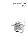
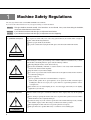
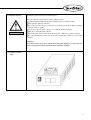
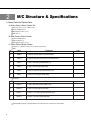
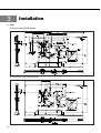
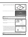
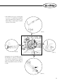
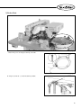
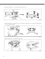
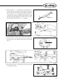
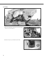
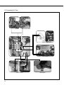
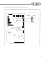
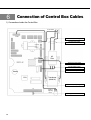
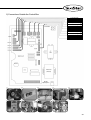
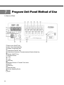
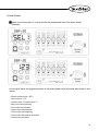
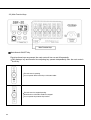
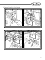
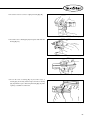
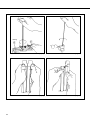
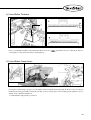
USER ’
S
MANUAL
SBF-20
Automatic Button Feeder
1) FOR AT MOST USE WITH EASINESS,
PLEASE CERTAINLY READ THIS MANUAL
BEFORE STARTING USE.
2) KEEP THIS MANUAL IN SAFE PLACE
FOR REFERENCE WHEN THE MACHINE
BREAKS DOWN.
SUNSTAR MACHINERY CO., LTD.
MME-051219
USER’S MANUAL
SBF-20
Automatic Button Feeder
lity
a
u
tQ
Besst Pricevice
Be st Ser
Be
1. Thank you for purchasing our product. Based on the rich expertise and
experience accumulated in industrial sewing machine production, SUNSTAR
will manufacture industrial sewing machines, which deliver more diverse
functions, high performance, powerful operation, enhanced durability, and
more sophisticated design to meet a number of user’s needs.
2. Please read this user’s manual thoroughly before using the machine. Make
sure to properly use the machine to enjoy its full performance.
3. The specifications of the machine are subject to change, aimed to enhance
product performance, without prior notice.
4. This product is designed, manufactured, and sold as an industrial sewing
machine. It should not be used for other than industrial purpose.
R
SUNSTAR MACHINERY CO., LTD.
1. Machine safety regulations ---------------------- 6
2. M/C structure & specifications ----------------- 8
1)
2)
3)
4)
5)
Basic parts and option parts ----------------------Machine structure ------------------------------------Machine specifications ------------------------------Control box specifications --------------------------Control box inner structure -------------------------
8
9
9
10
11
9. Button change ------------------------------------ 41
1)
2)
3)
4)
5)
6)
Changing feeding pin -------------------------------Changing button clamp -----------------------------Chute adjustment ------------------------------------Buttons that are not allowed to use -------------Using buttons whose diameter is less than 10mm --Button selector ----------------------------------------
41
42
43
44
44
45
10. Operation ----------------------------------------- 47
3. Installation ------------------------------------------ 12
1)
2)
3)
4)
5)
6)
7)
Table ---------------------------------------------------Button sewer & button feeder ---------------------Button bowl -------------------------------------------Air wiper ----------------------------------------------Filter regulator ----------------------------------------Connecting air tube ---------------------------------Exchanging button clamp ---------------------------
12
13
17
20
21
22
24
1) Building the button column ------------------------- 47
11. Maintenance -------------------------------------- 48
1)
2)
3)
4)
5)
6)
Changing spinning rubber --------------------------Changing chute motor ------------------------------Replacing chute belt & chute bearing -----------Control button thickness ----------------------------Control button clamp sensor ----------------------Adjusting the button revolving base return spring ---
48
48
49
53
53
54
4. Power voltage ------------------------------------- 25
1) Power voltage specifications ------------------------ 25
12. Troubleshooting ---------------------------------- 55
5. Changes according to frequency -------------- 26
13. Other ---------------------------------------------- 57
1) Motor specification change according to frequencies - 26
2) Installation of vibration connector according to frequencies --- 27
1) Initializing the machine ------------------------------- 57
2) Parameter setting ------------------------------------- 58
3) Parameter setting method --------------------------- 59
6. Connection of control box cables ------------- 28
1) Connections inside the control box --------------- 28
2) Connections outside the control box -------------- 29
14. Error signs and troubleshooting -------------- 61
15. Machine test function -------------------------- 62
7. Program unit panel method of use ----------- 30
1) Names of parts --------------------------------------2) Initial screen ------------------------------------------3) Key functions -----------------------------------------3-1) Displayer keys --------------------------3-2) Transfer time adjusting key -----------3-3) Main function keys ----------------------
30
31
32
32
33
34
1)
2)
3)
4)
5)
Motor test function (t-01) ---------------------------Solenoid test function (t-02) ------------------------Thread trimming cam sensor test function (t-03) --Cam sensor test function (t-04) -------------------Reset switch test function (t-05) -------------------
63
64
65
66
67
8. Test ------------------------------------------------- 39
1) By air valve -------------------------------------------- 39
2) By hand ------------------------------------------------ 40
5
1
Machine Safety Regulations
The safety signs in this manual are DANGER, WARNING and CAUTION.
If you do not follow these instructions, it may cause physical damage or machine breakdown.
DANGER : This sign should be observed carefully. If the instructions are not followed, it may cause harm during the installation,
conveyance and maintenance of the machine.
:
WARNING If you follow the instructions under this sign, you will prevent harmful effects.
CAUTION : If you follow the instructions under this sign, you will prevent errors from happening.
1-1) Machine Conveyance
Only experienced workers fully aware of the safety guide should carry the machine. When carrying the
machine, follow the following instructions.
At least 2 people should carry the machine.
To prevent accidents when carrying the machine, please clean all oil stains found in the machine.
DANGER
1-2) Machine Installation
WARNING
1-3) Machine Reparation
CAUTION
6
When installing the machine, physical damage such as machine malfunction or breakdown may occur due
to the machine's surrounding. Therefore, please satisfy the following conditions.
When unpacking the machine, start in order from the top.
Because dust and humidity contaminate or cause the machine to erode easily, install a dehumidifier or
air cleaner and clean the machine frequently.
Keep the machine away from direct sunlight.
Leave 50 cm of space between the machine and the wall on the right, left and back of the machine to
have sufficient repairing space.
Danger of explosion
Do not operate the machine in an environment inducive of explosives.
If the machine operation has no special guarantee, do not operate the machine on hazardous places
including those that use aerosol spray cans or places that have oxygen-related products in order to
avoid explosions.
This machine does not include lighting devices. You must supply and install your own lighting
equipment for your work area.
When the machine needs repair, a trained A/S technician from the company must carry out the repairing
job.
Before cleaning or repairing the machine, make sure to stop all machine operations and wait 5 minutes
until the machine becomes completely discharged.
You must not change any of the contents or specifications of the machine without previously consulting
with a SunStar company worker. These changes can threaten safe machine operations.
When repairing the machine, make sure to use genuine parts from our company.
After repair, make sure to put back all the safety covers that were removed during repair.
R
1-4) Machine Operation
WARNING
The SBF-20 is a button feeder made for industrial purposes.
Make sure to follow the instructions below when operating the machine.
Read this manual thoroughly and understand it exhaustively before operating the machine.
Wear appropriate clothes for work safety.
Do not put your hand or any part of your body near any machine part that moves (button feeding pin)
while the machine is operating.
Do not remove any safety plates or any type of cover while the machine is operating.
Make sure to connect all ground conductors.
Shut off all electric operations and make sure that the power is “OFF” before opening the control box.
If possible, install all strong electric wave sources such as high frequency welders, etc. away from the
machine.
[ Warning ]
Your hand or finger can be cut or injured due to the button feeding pin, so never put your
hand or any body part near the machine while the machine is operating.
1-5) Location of Caution
Signs
WARNING
HIGH VOLTAGE MAY CAUSE INJURY.
TURN OFF THE MAIN SWITCH AND
DISCONNECT THE POWER PLUG
BEFORE OPENING THE COVER.
7
2
M/C Structure & Specifications
1) Basic Parts and Option Parts
A. Button Sewer / Button Feeder Set
Basic Parts and Accessory of Button Sewer
Feeder and Button Bowl
Filter Regulator and Accessory
Table (Ass y)
B. Basic Parts of Button Feeder
Feeder and Button Bowl
Button Clamp(Ass y)
Filter Regulator and Accessory
C. Option Parts of Button Feeder
Pedal(Ass y) Pedal for exclusive use of Sunstar s button sewer
Table
No.
Name
Explanation
1
Table A
For Sunstar’s belt-type button sewer (SPS/A-B1202)
2
Table B
For Sunstar’s direct drive motor button sewer (SPS/B-B1202)
3
Table C
For JUKI’s chain-stitch type M/C(MB-373, 372)
4
Table D
For JUKI’s lock-stitch type M/C(LK-1903)
5
Table E
For Brother’s chain-stitch type M/C(CB3-B916, B917)
6
Table F
For Brother’s lock-stitch type M/C(BE-438C)
Note
Feeder Base
No.
Name
Explanation
1
Base A
For JUKI’s chain-stitch type M/C (MB-373, 372)
2
Base B
For JUKI’s lock-stitch type M/C (LK-1903)
3
Base C
For Brother’s chain-stitch type M/C (CB3-B916, B917)
4
Base D
For Brother’s lock-stitch type M/C(BE-438C)
Spinning Rubber Guide(S) Part that ONLY used for the button whose diameter is less than 10mm
8
Note
R
2) Machine Structure
Button Sewing M/C
Button Feeder
Button Clamp
Operation Box
Operation Box for
Button Sewing M/C
Button Bowl
Power Switch
Filter Regulator
Pedal Switch
3) Machine Specifications
Feeding and Sorting of Buttons
By Vibrator
Button Feed Mode
Automatic / Semi-Auto / Manual Mode
Button Size Control
Automatic Control Mechanism by a Sample Button
Button Feed Mode
Horizontal Feeding System
Compressed Air
0.49MPa (5.0 kgf/ )
9
4) Control Box Specifications
Motor
Specifications
Item
SBF-20
Power voltage
Single phase 220V
Frequency
50Hz , 60Hz
Main motor
S8I25GXCE
Chute motor
(Button feed motor)
Left, right rotating motor
(Button hold motor)
S6IO6GXCE
Vibrator
Temperature
10
50Hz
60Hz
Gear S8DA9B-K52 S8DA10B-L02
Head
50Hz
60Hz
M41A3G2Y
S6DA15B-K67 TS05-0061
50Hz , 60Hz
5
~ 40
Humidity
20% ~ 80%
Fuse
250V , 2A
Time to supply the buttons after sewing
Max : 244[ms] (Out of the factory: 24[ms])
Time to rotate left and right rubber
Max : 1.93[s] (Out of the factory: 760[ms])
Time for sewing twice
Max : 1.94[s] (Out of the factory: 380[ms])
Chute closing time
Max : 464[ms] (Out of the factory: 220[ms])
R
5) Control Box Inner Structure
Power Switch
AC Filter
Buzzer
CPU
Transformer
(24V/8.5V)
11
3
Installation
1) Table
A. Driven by belt (SPS/A-Series)
B. Direct Drive Type (SPS/B-Series)
12
R
2) Button Sewer & Button Feeder
When you install a feeder after an additional procurement together with Sunstar’s button sewer, please exchange the button clamp in the button
sewer which is provided with the button feeder referring to the corresponding the page 24 of it.
A. Fix the oil tube holder①, oil holder ②, control box③, power switch
④, and setting base⑤ on the table.
[ Fig. 1 ]
B. Attatch the bed cushion rubber to the setting base.
Cushion Rubber
[ Fig. 2 ]
C. Add the hinge metal and hinge rubber to the bed. Then insert the fixing
bolt into the hinge metal hole of point ① and fix the table as shown in
the [Fig.3].
Fixing
Bolt
Hinge Rubber
Hinge
[ Fig. 3 ]
[ Danger ]
The machine should be carried by more 2 people for safety.
13
D. Stand the machine as shown in the [Fig. 4], and then fix the machine
on the table after inserting the fixing blots into the hinge metal holes of
point ①.
[ Fig. 4 ]
E. Screw the bed fixing bolt on the back of the table as drawing [Fig. 5].
[ Fig. 5 ]
[ Danger ]
Since the machine is not perfectly installed on the table, extreme care is needed when you make the machine stand up not to
have any accident occurred.
F. Please kindly refer to Page 20 in the manual of the button sewer
concerning the connection of the button sewer connector and the
installation of other parts.
G. Temporary fix the 4 fixing bolt ① on the table after you properly put
button sewer on the table.
[ Fig. 6 ]
H. Start setting the button sewer and the feeder. Power on the button
sewer and adjust the operation box by using the provided basic pattern
no. 1 after inserting the button clamp no. 2 and the transfer plate no. 3
in the feeder. And correct the left backward pin among the 4 ones and
the center of needle exactly as shown in [Fig. 7] when it stops at the
center of the button clamp for a while by operating the feeding pin
manually during the power on.(please, refer to Page 40). Fix the feeder
on the table tightly by fastening 4 EAs of the fixing screw after the
setting.
Correcting the center with the needle
[ Fig. 7 ]
[ Danger ]
Please progress on by making sure the changed status of the setting when fastening the fixing screws.
14
R
I. After finishing previous pages, as drawing [Fig.
8], loosen ①, ② of button sewer and adjust to
make gap 0.5mm bewteen feeding pin① and
button clamp② as drawing [Fig. 9]. Tighten
again after correctly setting.
[ Fig. 8 ]
3
1~2
0.5
[ Fig. 9 ]
[ Fig. 11 ]
[ Fig. 10 ]
Drawing [Fig. 12], revolve the handle, loosen ①
bolt and adjust ② to make gap 2㎜ between ①
and ② when the feeding pin starts coming back
from above needle plate as drawing [Fig. 11].
Button clamp will break needle if you adjust ②
too high.
[ Fig. 12 ]
15
J. Attach the adjacent ① which monitors whether the button sewing
machine is functioning thread trimmer in the inner part of Arm. At that
time, fix the sensor (Set ① & ②) by using the screw ③.
①
②
③
[ Fig. 13 ]
Adjust the position of sensor to correct the distance from the end terminal
of the sensor ① to the thread loosening pin ④ to be about 1mm.
[ Fig. 14 ]
16
R
3) Button Bowl
[ Fig. 15 ]
A. Put in fixing screw after laying the table ring on the table.
[ Fig. 16 ]
B. Temporary fix the nut ① to attach the table ring and table.
①
[ Fig. 17 ]
17
C. Temporary fix the fixing nuts ①, ② after assemble vibrator base at the fixing screw.
[ Fig. 18 ]
D. Strongly tighten fixing nut ① of the [Fig.17] after correctly put the vibrator on rubber base. Press once to rubbers go into the hole. (Electric
wire has to be toward button supplier)
[ Fig. 19 ]
E. Temporary fix the fixing screw ① after put button feeder on vibrator.
[ Fig. 20 ]
18
R
F. Loosen fixing nuts ①, ② as in [Fig.18]. Use the setting gauge① to
adjust the chute belt (A) in [Fig.21] and the height of feeder entrance
(B) to be distant from each other by 1mm, and tighten the fixing nuts.
Loosen the fixing screw ① as in [Fig.20] and use the setting gauge ②
to make the chute’s right side (C) distant from the button feeder’s right
side (D) by 2mm and then tighten the screw. If the distance is incorrect,
make the adjustment by using the nuts ①, ② as in [Fig.18] .
1mm
Setting gauge
2mm
2mm
C D
1mm
A
B
[ Fig. 21 ]
G. Lock the handle ① in drawing [Fig. 22] after setting vibrator and
button bowl. And connect vibrator jack and feeder jack as drawing
[Fig. 23].
[ Fig. 22 ]
[ Fig. 23 ]
H. Strongly tighten the bolt ① in drawing [Fig. 24] after all setting. (It is
very important to vibration.)
①
[ Fig. 24 ]
19
4) Air Wiper
[ Fig. 25 ]
A. Please fix the wiper bracket A in the button sewer body by using the
fixing screw ① as shown in [Fig. 26].
①
A
[ Fig. 26 ]
B. Adjust the air wiper ① to prevent that thread out from needle.
①
[ Fig. 27 ]
20
R
5) Filter Regulator
Don’t put oil in Air filter
A
Gauge pressure has to be 0.5MPa(5㎏f/㎠). (Caution : Minimum 4㎏f/㎠~maximum 6㎏f/㎠. The machin go wrong under airpressure 4㎏f/㎠.)
Hold up to turn ①. Air pressure will be up if you turn it left. Air pressure will be down of you turn it right. Please press a handel after adjusting
airpressure. Loosen ② to remove the water in A after long time works. The cylinder will be wrong if water exist in A.
21
6) Connecting Air Tube
Air Wiper
Button Clamp Cylinder
Clutch Cylinder
Chute Cylinder
Chute Air Blower
22
Filter Regulater
R
Air System Circuit Diagram
23
7) Exchanging Button Clamp
Among the users of‘SPS/A-B1202’and‘SPS/B-B1202’, if you want to use‘SBF-20’additionally, you shall exchange the existing button
clamp into an exclusive button clamp.
A. Separate the tension adjusting screw (Set) ①.
Take out the button clamp holder shaft③ by unfastening the fixing
screw (2EA)②.
[ Fig. 28 ]
B. Separate the button clamp (Set) ④ as shown in [Fig. 28].
[ Fig. 29 ]
C. After mounting the exclusive button clamp ①, fix the button clamp ①
by using the button clamp holder ② and the fixing screw (1EA) ③.
Finally attach the tension adjusting screw (Set) ④.
④
①
①
②③
[ Fig. 30 ]
24
R
4
Power Voltage
1) Power Voltage Specifications
A. Exclusive use for single phase 220V
B. Changing the power voltage
Change the power voltage by using a transformer
Transformer model being used: SBF-20-220
If the transformer model being used is incorrect, you may damage the control box. Always use the
instructed model.
CAUTION
25
5
Changes According to Frequency
You may use both the 50Hz and 60Hz frequencies for the model SBF-20.
The specifications for the motor and vibrator change according to these two interchangeable frequencies.
1) Motor Specification Change According to Frequencies
Category
Model
Gear Head
50Hz
60Hz
S8I25GXCE
Chute Motor
(Button Feed Motor)
S6IO6GXCE
The left and right rotating motor (button holding motor) does not use a gear head.
If the gear head specifications according to frequencies do not match, the button feeding operation may
not operate smoothly.
CAUTION
26
R
2) Installation of Vibration Connector According to Frequencies
buzzer
CPU
27
6
Connection of Control Box Cables
1) Connections Inside the Control Box
Power Switch
Power Switch Connecting Cable
AC-Filter Input Cable
AC
Filter
Transformer Input Cable
AC-Filter Output Cable
Transformer Output Cable
Buzzer
CPU
Transformer
(24V/8.5V)
Vibrator Intensity Adjusting Cable
Vibration
Adjusting
Device
28
Program Unit Cable
R
2) Connections Outside the Control Box
Cooling Fan Cable
Solenoid Output Cable
Thread Trimming Cam Connecting Cable
Reset Switch Connecting Cable
Power Switch
Cam Sensor Connecting Cable
Right, Left Rotating Motor Connecting Cable
Main Motor Connecting Cable
Chute Motor Connecting Cable
Power Cable
Vibrator Output Cable
Buzzer
Transformer
(24V/8.5V)
Vibration
Adjusting Device
29
7
Program Unit Panel Method of Use
1) Names of Parts
Main motor ON/OFF Key
Auto / Semi-Auto Mode Key
Double / Single Mode Key
Chute Motor ON/OFF Key
Chute Motor Clockwise / Counterclockwise Rotation Mode Key
Vibrator ON/OFF Key
Displayer Screen
+ Key
– Key
Clear Key
Displayer Screen of 'Transfer Time' Value
Up Key
Down Key
Parameter Key
Vibrator Adjusting Device
Light
30
R
2) Initial Screen
When you turn the power on, you will see the last programmed work of the button feeder.
(Example)
On the figure above, the programmed work of the button feeder before the power was turned on is as
follows:
Button feeding mode : SEL 1
Work amount : 123
Chosen value for transfer time : 0
Main motor was operating
Auto mode was selected
Single mode was selected
Chute motor was operating
Chute motor was rotating clockwise
Vibrator was operating
31
3) Key Functions
3-1) Displayer Keys
Displayer Keys
When buttons are fed after sewing work is completed, the number in the displayer will automatically
increase by +1.
If the buttons are fed, the number on the displayer will automatically increase by +1.
The numbers “0” to “9999” will appear on the screen. After “9999”, the number “0” will appear again.
Screen showing work amount
Everytime this key is pressed, the number in the displayer will increase by +1.
(If you continue to press this key, the number will increase automatically.)
Key
Everytime this key is pressed, the number on the displayer will decrease by –1.
(If you continue to press this key, the number will decrease automatically.)
Key
Reset the number appearing on the displayer to “0”.
Key
32
R
3-2) Transfer Time Adjusting Key
Transfer Time Adjusting Key
This key controls the time the button feeder starts feeding buttons after sewing work is completed.
On this screen you will see the numbers “0” to “9”. After “9”, number “0” will appear again.
Value of transfer time
Everytime this key is pressed, the transfer time will increase by +1.
(If you keep on pressing this key, the numbers will increase automatically.)
Up Key
Everytime this key is pressed, the transfer time will decrease by –1.
(If you keep on pressing this key, the numbers will decrease automatically.)
Down Key
Number “0” signifies that the buttons will be fed at the fastest speed while number “9” signifies that
the buttons will be fed at the slowest speed.
33
3-3) Main Function Keys
Main Function Keys
Main Motor's ON/OFF Key
Everytime these keys are pressed, the main motor will turn on and off repeatedly.
The displayer key and transfer time adjusting key operate independently from the main motor's
on/off key.
The main motor is operating.
You can operate all the function keys of the button feeder.
The main motor has stopped operating.
All the functions of the button feeder have stopped.
You can operate the parameter key functions.
34
R
Auto/Semi-Auto Mode Key
Everytime you press these buttons, the Auto or Semi-Auto modes are repeated.
You can operate the functions of these keys when the main motor is operating.
Buttons are fed automatically after sewing work is completed.
The button feeder will not feed buttons until the sewing work is completed.
When working with a lot of sewing materials, it use.
Press the reset switch and the machine will feed one button at a time.
RESET SWITCH
35
Double / Single Mode Key
This key is used for button sewing or when you want to sew buttons twice as fast or faster than the
basic sewing time. This key is used only for Chain Stitch button sewing machines.
You can operate the functions of these keys when the main motor is operating.
When using button sewing machines except chain stitch, select and use the single mode.
This key is used for chain stitch button sewing machines only.
Adjustment of sewing time can be done on parameter “A-01”.
(Refer to the page on parameter setting.)
36
R
Chute Motor ON/OFF Key
This key turns ON/OFF the button feeding belt.
You can operate the functions of these keys when the main motor is operating.
Chute motor is operating.
Chute motor has stopped.
Chute Motor's Clockwise and Counterclockwise Rotation Mode Key
You can operate the functions of these keys when the main motor is operating.
You can operate this key when the chute motor is operating.
The chute motor will rotate clockwise and the buttons can be fed through the button feeding pin.
The chute motor will rotate counterclockwise and the buttons on the button feeding belt will be sent
towards the direction of the vibration.
37
Vibration ON/OFF Key
You can operate the functions of these keys when the main motor is operating.
Refer to the page 27 on selection of connectors according to local frequency type.
Vibration is operated and buttons are sent to the feeding belt.
Vibration has stopped.
Adjusting Vibration Intensity
Vibration Adjusting Device
If you turn the vibration adjusting dial to the right, the vibration becomes stronger.
The user must adjust the intensity of the vibration according to the programmed work.
38
R
8
Test
1) By Air Valve
[ Fig. A ]
The button clamp opens by operating the button clamp cylinder when turn the
valve handle ③ as shown in [Fig. A]. Please shut off the valve tightly after
testing.
Feeder’s clutch cylinder and chute cylinder will be simultaneously worked when
you turn the valve handle ② as shown in [Fig. A]. After open valve, if you turn
the right handle to the left, transfer pin will be moved, please close the valve
after testing.
The air exhausts from the blowers (2 positions) under the button transfer chute
when turn the valve handle ① as shown in [Fig. A]. Please shut off the valve
tightly after operating the valve.
39
2) By Hand
①
Another method to move feeding pin : Disconnect air
jack first, feeder’s clutch will be open if you put thin
stick into a hole ① screw dirver such as drawing [Fig.
A]. If you turn the handle as drawing [Fig. B], the
feeding pin will be moved as drawing [Fig. C].
[ Fig. A ]
[ Fig. B ]
[ Fig. C ]
40
R
9
Button Change
1) Changing Feeding Pin
Button
No.
1
2
3
4
5
No. of hole
Range fo
Sewing(mm)
Expansion &
Reduction(%)
2
4
2
4
2
4
2
4
2
4
2.5
2.2 2.2
2.9
2.7 2.7
3.5
3.2 3.2
4
3.8 3.8
4.5
4.5 4.5
74%
65%
85%
79%
103%
94%
118%
112%
132%
132%
Note
Standard range
3.4( 3.4)
[100%]
[ Fig. 31 ]
A. Put a button in button hole size check board which is suitable number of pin as drawing [Fig. 31]. For example, as drawing [Fig. 31] use
feeding pin 4 hole No. 3 if the button hole is suit able for 4 hole No. 3.
①
[ Fig. 32 ]
B. After selecting the feeding pin, press ① part and loosen fixing screw ② to change transfer pin as shown in the [Fig. 32]. For example, as
drawing [Fig. 31] use feeding pin 4 hole No. 3 if the button hole is suit able for 4 hole No. 3. (Regarding selection of feeding pin, please refer
to the attached sticker in the machine.) Please establish a range of sewing (expansion and reduction) for the button sewing machine dependent
on the interval between button holes by referring the above Table. Please establish 94% of the expansion and reduction for the 4 hole No. 3.
41
2) Changing Button Clamp
A
[ Fig. 33 ]
A. Insert the buttons to be used into (A) as in [Fig. 33]. Depending on the colors pointed by the pin as in [Fig. 33], choose the number of the
button clamp. For example, when the pin ① points at yellow, choose No. 2 button clamp (as for the choice of button clamps, see the sticker
attached to the machine).
B. Choose a button clamp as in [Fig. 33], and loosen and remove the
fixing screw ① as in [Fig.34]. Insert and tighten the button clamp (for
the choice of button clamps, see the sticker attached to the machine).
[ Fig. 34 ]
C. Replace the button clamp chosen in [Fig. 33] with reference to
[Fig.34]. Then the button holes get automatically aligned with the
center of the needles. Therefore do not loosen the fixing screws ①, ②
as in [Fig.35] to make adjustment.
[ Fig. 35 ]
42
R
3) Chute Adjustment
This machine is suitable for the buttons whose external diameter is 10mm or above. If it is necessary to use buttons whose external diameter is
less than 10mm (up to 8mm in external diameter), make additional purchase of optional parts as in page 8 for replacement.
(O)
Button
[ Fig. A ]
(X)
[ Fig. B ]
[ Fig. 36 ]
A. Turn ① in the arrow direction.
[ Fig. 37 ]
B. Push ② backward and insert buttons. When inserting buttons, make sure that buttons are placed
face-down as in [Fig. A]. If the buttons are placed in the opposite way as in [Fig. B], the buttons
are not fed to the chute.
[ Fig. 38 ]
C. Insert buttons into ③ and move ① back to the original position. Then the buttons are sorted by
size, thickness and they are aligned along with the center at the same time.
③
[ Fig. 39 ]
43
4) Buttons that Are Not Allowed to Use
For the buttons whose shapes are the following, it shall not be allowed to work using ‘The specifications taking out of factory for SBF-20’. You
shall place a purchase order with our company after a consultation with us when you are going to use the following buttons.
No.
Name
Explanation
Note
1
Paduk Button
2
Convex Button
3
Slope Button
4
Shell Button
-
Button that made of shell.
5
Symmetry Button
-
Shape of upper part and that
of lower part are same.
5) Using Buttons whose Diameter Is Less than 10mm
When you will use buttons whose outer diameter is less than 10mm, you
shall exchange “spinning rubber guide” into “spinning rubber guide
(splace) of the optional part” (referring to Page 8).
Please exchange it referring to the following Fig.
Spinning Rubber
Guide (S)
44
R
6) Button Selector
A. Put the button in feeder, loosen ① and adjust ② to make button pass one by one. Tighten ①.
[ Fig. 40 ]
B. When you use
direction. If you lift up ④
shaped button, loosen ①, ② and turn ③ to the clockwise direction ④ rises. It move down if turn to opposite
shaped button will be passed,
shaped button will be fallen.
A
[ Fig. 41 ]
C.
B
[ Fig. 42 ]
shaped button : loosen ① and adjust ②, tighten ① again as
shown in the [Fig. 43].
[ Note ]
In this occasion the gap in drawing left has to be 2mm.
(Continue next page drawing [Fig. 44])
2mm
[ Fig. 43 ]
45
D. As drawing [Fig. 44], loosen ① to adjust ② to make right side button
pass and wrong side button falls down to A part, and then tighten ①.
A
[ Fig. 44 ]
E. To select
shaped button. After setting as drawing [Fig. 43],
loosen ① to adjust ② that right side button pass, wrong side button
falls down to A part, and then tighten ①. The sawtooth can select all
kind of buttons which has a furrow.
A
[ Fig. 45 ]
F. As drawing [Fig. 46], loosen ① to adjust ② to make the buttons go
into the chute and tighten ① as drawing [Fig. 47].
[ Fig. 46 ]
[ Fig. 47 ]
46
R
10
Operation
1) Building the Button Column
Turn A in the right direction as in [Fig. 48] for the button column reeling.
Loosen ① to adjust the height of ② and tighten ① again.
If the button column reeling is unnecessary, turn A in the left direction as in [Fig. 49].
①
[ Fig. 48 ]
[ Fig. 49]
B
47
11
Maintenance
1) Changing Spinning Rubber
①
[ Fig. 50 ]
Lift up ① to change spinning rubber as drawing [Fig. 50].
2) Changing Chute Motor
[ Fig. 51 ]
Loosen the fixing screws ① and ②. Loosen all the fixing screws, pull out the chute and change new chute motor. Tighten the fixing screws ①,
② after making horizon K part and chute motor when you reassemble the motor.
48
R
3) Replacing Chute Belt & Chute Bearing
[ Fig. 52 ]
[ Fig. 53 ]
[ Fig. 54 ]
[ Fig. 55 ]
A. Disconnect the chute moter jack as drawing [Fig. 52].
B. Loosen the screws as drawing [Fig. 53, 54, 55] in order.
49
[ Fig. 56 ]
[ Fig. 57 ]
C. Take out the button lifter ② as drawing [Fig. 56] after pushing ①.
[ Fig. 58 ]
D. Loosen the screw ③ to take out button presser ④ as drawing [Fig. 57. 58].
Loosen the screw to take out chute pillar as drawing [Fig. 59].
50
[ Fig. 59 ]
R
E. Loosen the screw to loose motor coupling as drawing [Fig. 60].
[ Fig. 60 ]
F. Loosen the screw as drawing [Fig. 61] and separate chute both side
drawing [Fig. 62].
[ Fig. 61 ]
[ Fig. 62 ]
G. Loosen the screw as drawing [Fig. 63] loosen the screws as
drawing [Fig. 64, 65, 66], and then replace the belt as drawing
[Fig. 67]. Likewise, replace the bearing in drawing [Fig. 64]. After
replacing, reassemble in counter order.
[ Fig. 63 ]
51
Bearing
52
[ Fig. 64 ]
[ Fig. 65 ]
[ Fig. 66 ]
[ Fig. 67 ]
R
4) Control Button Thickness
[ Fig. 68 ]
In the occasion that buttons doubling as drawing B, button will not fed. To select
control height of ③ and ④ 0.3mm as drawing A, and then tighten ①.
shaped buttons. Loosen ① of [Fig. 68] to adjust ② to
5) Control Button Clamp Sensor
[ Fig. 69 ]
If closing time of button clamp is not proper, open the supplier clutch and manually turn the right handle the direction of the arrow. Stop the
handle when the feeding pin is middle of needle plate and chute. (As above drawing, adjust screw and feeding pin make parallel) Loosen ① to
adjust ② and ③ as drawing B and tighten ①.
※ Confirm that buton clamp smoothly open and close.
53
6) Adjusting the Button Revolving Base Return Spring
Small Buttons (default)
Medium-size Buttons
[ Fig. 70 ]
When shipped out from the factory, it is set for small buttons as default.
In case of using medium-size buttons, increase the compression pressure a bit higher compared with smaller buttons.
A. Loosen the collar screw ①.
B. Tighten the collar screw making sure that the upper side of the collar is distant from the shaft edge by 4mm.
54
R
12
Troubleshooting
No.
Trouble
Solution
In the occasion that button clamp wrongly hold the
button.
Note
Special shaped buttons, loosen A and adjust height of
B of button sewer depends on button shape when
button clamp wrongly hold or buttons fall down.
※ Special button
cover to prevent
buttons’s
separation as the
No. 4’s picture.
(Special order)
A
1
B
Reset exact center of button clamp and feeding pin
as page 13.
Normality
Abnormality
In the occasion that buttons fall down between chute
and feeding pin.
Normality
Normality
Abnormality
Assemble the setting device and move feeding pin as
drawing [Fig. 1], [Fig. 2]. Correctly set to the pin into the
hole when their condition is as drawing 3.
Abnormality
2
[Fig.1]
[Fig.2]
[Fig.3]
[Fig.4]
[Fig.5]
55
No.
3
4
5
56
Trouble
Machine’s timing is not correct.
In case where buttons are not fixed by the button
clamp
Button clamp opening and closing is not smooth.
Solution
Note
Check air pressure is between 4~6Kgf/㎠
In case where buttons are not fixed due to
inappropriate height of the button clamp lifter
Refer to 53 pages
Sometimes 2nd sensor timing makes this problem.
Refer to 53 page.
Put oil to button clamp.
R
13
Other
1) Initializing the Machine
A. To turn the power on, press the “+”, “–” and “CL” keys simultaneously.
B. On the displayer screen window you will see the letter
appear on the displayer.
l
n
l
t
and soon the number “0” will
Program Unit Panel Condition after Initialization
Parameter Condition after Initialization
Type
A-01
A-02
A-03
A-04
Value
1
2
4
SEL 1
57
2) Parameter Setting
The button feeder has four types of parameters.
If the parameter set value is incorrect, the button feeder may not operate properly.
Type
Sewing Time (Double Key)
“A-01”
Contents
This is a parameter used for chain stitch sewing machines.
The value range is 0 ~ 9.
You adjust this number from 1~3 according to the button size.
Chute Closing Time
“A-02”
1 ~
3
Valve
1
2
3
Button size
8~10mm
11~25mm
25~32mm
The value range is 0 ~ 4.
Do not set the number higher than 4.
(The buttons can fall to the floor from the feeding belt while the buttons are being fed)
Operating Time for the Left and Right
Rotating Motor
“A-03”
Sewing pattern-based button
feed mode
“A-04”
This parameter is used for the operating time for the left and right rotating motor which
enables buttons to attach to the button feeding pin more easily.
The value range is 0 ~ 9.
Do not set the number higher than 5.
This is a parameter of choosing a button feed mode depending on the button sewing
pattern in case of SPS/A(B)-1202.
The choice can be made between “SEL1” and “SEL2”.
SEL1 – one trimming
SEL2 – two trimmings
See the manual of SPS/A(B)-1202 regarding sewing patterns.
When using the chain stitch machine, select the SEL1 mode.
If the button feed mode is not consistent with the sewing pattern, damage to the machine might occur.
Therefore users shall make sure what button feed mode shall be used in accordance with sewing pattern.
CAUTION
58
R
3) Parameter Setting Method
In order to set the parameter, the main motor first must be stopped.
All parameter setting methods are as shown below.
(Example) Setting the chute closing time
- The chute closing time is set to “2”
A. Stop the main motor.
B. If you press the “Prog” key, you will see the
letters “Prog” on the displayer screen along with
the buzzer sound.
C. After the buzzer sounds, you will see the
parameter setting screen on the displayer.
“Sewing time (A-01)”
D. If you press the “+” key, you will see the “Chute
closing time (A-02)” adjusting parameter on the
displayer.
59
E. If you press the “CL” key, you will see the
time setting value on the displayer screen.
You can choose the value by pressing the
“+” key and “─” key.
(All parameter setting value range is 0 ~ 9)
F. If you need to choose a new value, press the
“CL” key and you will return to the parameter
setting screen.
G. If you press the “Prog” key, you will hear the
buzzer sound for 2 seconds. And you will
also see the displayer screen(Prog) and the
light blink with the former work amount
value.
60
R
14
Error Code
Error Signs and Troubleshooting
Contents
Cause and troubleshooting
E-01
Check the thread trimming cam sensor connector
Check for bad connection to the connector
E-02
Check the cam sensor connector
Check for bad connection to the connector
E-03
Check the reset switch connector
Check for bad connection to the connector
E-04
Check the air pressure
Check for bad connection to the connector
61
15
Machine Test Function
Test Mode Setting Method
A. Press the UP and DOWN key simultaneously to turn the power on.
Along with the buzzer sound, you will see the word “tESt” on the displayer
screen. This enables you to enter the test mode stage.
You will see “t-01” on the displayer.
B. Select the test mode number with the “+” and “–” keys.
(Mode range : 1~5)
C. Install the selected number by pressing the “Prog” key.
Test Mode Type
Test Mode Type
62
Contents
t-01
Motor test
t-02
Solenoid test
t-03
Thread trimming cam sensor test
t-04
Cam sensor test
t-05
Reset switch test
R
1) Motor Test Function (t-01)
A. After selecting the test mode “t-01”, press the “Prog” key.
If the light comes on the LED on top of the Prog key, the machine is ready to
make the motor test.
B. Press the “Main Motor” key and check the main motor operation.
When the main motor is operating, the light goes on the lamp and the letters “on”
appear on the displayer.
When the main motor stops, the light goes off the lamp and the letters “off” will
appear on the displayer for 1 second. Then you will see “t-01” on the screen.
Main Motor Operating
Main Motor Stopped
C. Press the “Function” key and check the chute motor operation
(button feed belt motor).
When chute motor is operating, the light goes on the lamp and the letters “on”
appear on the displayer.
When the chute motor stops, the light goes off the lamp and the letters “off” will
appear on the displayer for 1 second and later you will see “t-01” on the screen.
Chute Motor Operating
Chute Motor Stopped
D. Press the “Stitch Time” key and check the left, right rotating motor operation.
When the left, right rotating motor is operating, the light goes on the lamp and the
letters “on” appear on the displayer.
When the left, right rotating motor stops, the light goes off the lamp and the
letters “off” will appear on the displayer for 1 second. Then you will see “t-01” on
the screen.
Left, Right Rotating
Motor Operating
If the rotating rubber gets stuck on the button feeding pin, the motor may not
operate properly.
If this happens, lift the motor slightly. This will enable you to check more clearly
whether the motor is operating properly.
Left, Right Rotating
Motor Stopped
E. Press the “Prog” key and the test will end.
The light on the lamp will turn off.
63
2) Solenoid Test Function (t-02)
A. After selecting the test mode “t-02”, press the “Prog” key.
If the light comes on the LED on top of the Prog key, the machine is ready to
make the solenoid test.
B. Press the “Main Motor” key and check the operation of solenoid 1.
When solenoid 1 is operating, the light goes on the lamp and the letters “on”
appear on the displayer.
When solenoid 1 stops, the light goes off the lamp and the letters “off” will appear
on the displayer for 1 second. Then you will see “t-02” on the screen.
Solenoid 1
Solenoid 1
C. Press the “Function” key and check the operation of solenoid 2
When solenoid 2 is operating, the light goes on the lamp and the letters “on”
appear on the displayer.
When solenoid 2 stops, the light goes off the lamp and the letters “off” will appear
on the displayer for 1 second. Then you will see “t-02” on the screen.
Solenoid 2
Solenoid 2
D. Press the “Stitch Time” key and check the operation of solenoid 3
When solenoid 3 is operating, the light goes on the lamp and the letters “on”
appear on the displayer.
When solenoid 3 stops, the light goes off the lamp and the letters “off” will appear
on the displayer for 1 second. Then you will see “t-02” on the screen.
Solenoid 3
Solenoid 3
E. Press the “Prog” key and the test will end.
The light on the lamp will turn off.
64
R
3) Thread Trimming Cam Sensor Test Function (t-03)
A. After selecting the test mode “t-03”, press the “Prog” key.
If the light comes on the LED on top of the Prog key, the machine is ready to
make the thread trimming cam sensor test.
B. Softly move the machine's pulley to the left and right and check the signals detected
from the thread trimming cam sensor.
If the thread trimming cam comes in contact with the sensor, a signal will be
detected, and you will see the sign “on” on the screen.
If the thread trimming cam is separated from the sensor, a signal will not be
detected, and you will see the sign “off” on the screen.
Sensor Signal Defected
YES
Sensor Signal Defected
NO
C. Press the “Prog” key and the test will end.
The light on the lamp will turn off.
Thread Trimming Cam Sensor
65
4) Cam Sensor Test Function (t-04)
A. After selecting the test mode “t-04”, press the “Prog” key.
If the light comes on the LED on top of the Prog key, the machine is ready to
make the thread trimming cam sensor test.
B. Place an iron mass (ex: screwdriver) on the cam sensor signal detecting area and
check whether the machine can detect signals.
If the iron mass comes in contact with the sensor, a signal will be detected, and
you will see the sign “on” on the screen.
If the iron mass is separated from the sensor, a signal will not be detected, and
you will see the sign “off” on the screen.
Sensor Signal Detected
YES
Sensor Signal Detected
NO
C. Press the “Prog” key and the test will end.
The light on the lamp will turn off.
Cam Sensor
66
R
5) Reset Switch Test Function (t-05)
A. After selecting the test mode “t-05”, press the “Prog” key.
If the light comes on the LED on top of the Prog key, the machine is ready to
make the reset switch test.
B. If you press the reset switch key, it will test whether the machine can detect the
signal.
If the reset switch is pressed, a signal will be detected, and you will see the sign
“on” on the screen.
If the reset switch is not pressed, a signal will not be detected, and you will see
the sign “off” on the screen.
Reset Switch Pressed
Reset Switch Not Pressed
C. Press the “Prog” key and the test will end.
The light on the lamp will turn off.
Reset Switch
67