1
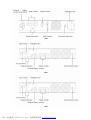
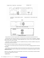
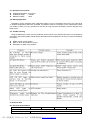
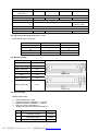
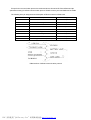
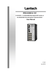
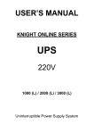
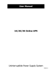
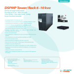
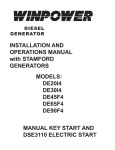
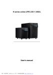
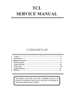
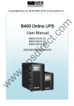
H series array online UPS 1-6KRS/L
User ’s manual
1
PDF 文件使用 "pdfFactory Pro" 试用版本创建 www.fineprint.cn
Contents
1. Introduction----------------------------------------------------------------------------------------------------------------------1
2. Safety instructions-------------------------------------------------------------------------------------------------------------2
3. System description-------------------------------------------------------------------------------------------------------------4
3.1. Front panel-----------------------------------------------------------------------------------------------------------------4
3.2. Rear panel------------------------------------------------------------------------------------------------------------------5
4. Maintenance---------------------------------------------------------------------------------------------------------------------7
4.1. Operation environment--------------------------------------------------------------------------------------------------7
4.2. Battery application--------------------------------------------------------------------------------------------------------7
4.3. Trouble shooting-----------------------------------------------------------------------------------------------------------7
5. Technical data-------------------------------------------------------------------------------------------------------------------8
5.1. Electrical specifications-------------------------------------------------------------------------------------------------8
5.2. Typical stored energy time----------------------------------------------------------------------------------------------8
5.3. Mechanical data-----------------------------------------------------------------------------------------------------------8
5.4. CE conformity--------------------------------------------------------------------------------------------------------------9
5.5. Communication port------------------------------------------------------------------------------------------------------9
2
PDF 文件使用 "pdfFactory Pro" 试用版本创建 www.fineprint.cn
1. Introduction
This array online UPS supplies power immediately to prevent the data lost and your system damaged
when the main power is abnormal. With WinPower software, the uninterruptible power supply (UPS) will
safely store data and shut down your network operating system before the battery is fully discharged,
whether you’re there or not. It provides perfect protection specifically for fileservers, minicomputers, internet
hubs, telecommunication systems and other mission-critical applications.
This array online UPS includes: 1KRS(L), 2KRL, 3KRL, 6KRL. The models with L extension allow for
expanding runtime by simply plugging in additional battery packs.
2. Safety instructions
Please read the following user manual and the safety instructions before installing the unit and starting it
up!
Transport
Please transport the UPS system only in the original packaging (to protect against shock and impact).
Set-up
Ø
Ø
Ø
Ø
Condensation may occur if the UPS system is moved directly from a cold to a warm environment. The
UPS system must be absolutely dry before being installed. Please allow an acclimatization time of at
least two hours.
Do not install the UPS system near water or in damp environment.
Do not install the UPS system where it would be exposed to direct sunlight or near heat.
Do not block off ventilation openings in the UPS system’s housing.
Installation
Ø
Ø
Ø
Ø
Do not connect appliances or equipment which would overload the UPS system (e.g. laser printers) to
the UPS output socket.
Place cables in such a way that no one can step on or trip over them.
Do not connect domestic appliances such as hair dryers to UPS output sockets.
The UPS can be operated by any individuals with no previous technical experience.
The following for 1KRS(L)/2KRL/3KRL specially:
Ø
Ø
Ø
Assure to connect with the earth reliably.
The building wiring socket outlet (shockproof socket outlet) must be easily accessible and close to the
UPS system.
With the installation of the equipment, the sum of the leakage current of the UPS and the connected
consumer does not exceed 3.5mA.
The following for 6K specially:
Ø
Ø
Ø
Warning -- this is a product for restricted sales distribution to informed partners. Installation
restrictions or additional measures may be needed to prevent disturbances.
A readily accessible disconnect device shall be incorporated in the building installation wiring and the
disconnect device must be easily accessible and close to the UPS system.
This is permanently connected equipment and only qualified maintenance personnel may carry out
installations.
Operation
Ø
Ø
Ø
The UPS system features its own, internal current source (batteries). The UPS output sockets may be
still exists even if the UPS system is not connected to the building wiring socket outlet.
In order to fully disconnect the UPS system, firstly press the standby switch then disconnect the mains
lead.
Ensure that no fluids or other foreign objects can enter the UPS system.
Maintenance, servicing and faults
3
PDF 文件使用 "pdfFactory Pro" 试用版本创建 www.fineprint.cn
Ø
The UPS system operates with hazardous voltage. Repair may be carried out only by qualified
maintenance personnel.
Caution -- risk of electric shock. Even some the unit is disconnected with the mains power supply (building
wiring socket outlet), components inside the UPS system are still connected to the battery and are still
electrically live and dangerous.
Ø
Ø
Before carrying out any kind of servicing and/or maintenance, disconnect the batteries and verify
that no current is present and no hazardous voltage exist in the terminals of high capability capacitor
such as BUS-capacitors.
Only persons adequately familiar with batteries and with the required precautionary measures may
exchange batteries and supervise operations. Unauthorized persons must be kept away from the
batteries.
Caution -- risk of electric shock. The battery circuit is not isolated from the input voltage. Hazardous
voltages may occur between the battery terminals and the ground. Before touching any operation, please
verify that no voltage is present!
Ø
Batteries may cause electric shock and have a high short-circuit current. Please take the
precautionary measures specified below when working with batteries:
-- remove wristwatches, rings and other metal objects
-- use only tools with insulated grips and handles.
Ø
Ø
Ø
Ø
When exchange batteries, install the same number and type of batteries.
Do not attempt to dispose of batteries by burning them. This could cause battery explosion.
Do not open or destroy batteries. Escaping electrolyte can cause injury to the skin and eyes. It may be
toxic.
Please replace the fuse only with a fuse of the same type and amperage in order to avoid fire hazards.
3. System description
3.1. Display panel
The UPS power control and operating indicators are located on the front display panel.
ON-SWITCH
Ø
Ø
The UPS can be turned on by pressing ON-SWITCH button for at least 1 second.
The acoustic alarm can be deactivated by pressing ON-SWITCH button.
4
PDF 文件使用 "pdfFactory Pro" 试用版本创建 www.fineprint.cn
STANDBY-SWITCH
The inverter can be turned off by pressing STANDBY-SWITCH. The output can be provided by the mains
power via the bypass.
AC input LED
Ø
Ø
Lights up when the mains power is normal.
Blinks when the mains power is abnormal or the live conductor and the neutral conductor reversed at
the input.
UPS ON LED
Lights up when output power provided by the mains power via the inverter.
Battery LED
Lights are up when the mains power is failed and the inverter is powered by the batteries.
Bypass LED
Lights up when output power provided by the mains power via the bypass.
Alarm LED
Lights up when the UPS system is in fault condition, at the same time, an acoustic warning signal is issued
every second.
Indicator #
Ø
Ø
Load level signaled when the AC input LED lighting up.
Battery level signaled when the battery LED lighting up.
Indicators
Indicator 1~5
Indicator 2~5
Load level
96%-105%
76%-95%
Indicators
Indicator 1
Indicator 1~2
Battery level
1%-35%
36%-55%
Indicator 3~5
56%-75%
Indicator 1~3
56%-75%
Indicator 4~5
36%-55%
Indicator 1~4
76%-95%
Indicator 5~5
1%-35%
Indicator 1~5
96%-100%
3.2. Real panel
The rear panels of your UPS and battery pack can be found among below drawings. The input and output
connectors and some other useful connectors are on the rear panel.
5
PDF 文件使用 "pdfFactory Pro" 试用版本创建 www.fineprint.cn
1KRL
2KRL
3KRL
6
PDF 文件使用 "pdfFactory Pro" 试用版本创建 www.fineprint.cn
6KRL
Battery pack for 1KRS(L)/2kRL/3KRL
Battery pack for 6KRL
Surge protection: provide a surge protection for telephone fax and network line protectors and so on.
Communication port: WinPower software can be used with the UPS for power management. Standard
serial interface cable is compatible with 1KRS(L)/2KRL/3KRL UPS, however, only the special cable applied
with the UPS can be used on 6K UPS.
Input/output: if socket is available, just insert compatible cable plug; if terminal is available, wiring can be
completed by professional electrician.
Note: terminal cover should be put back for safety reason after wiring completed.
Input breaker: if the breaker pops out/off, reduce the load on the UPS by unplugging equipment and reset
the breaker.
External battery socket: special cable is offered for the battery pack, insert one end into the external battery
socket on the UPS, the other to the battery pack, the same packs can be paralleled with together to achieve
desired back up time.
Notes: one chain of battery packs can be connected to one UPS only; only the battery connectors marked
with the equal voltage can be connected.
4. Maintenance
7
PDF 文件使用 "pdfFactory Pro" 试用版本创建 www.fineprint.cn
4.1. Operation environment
l
l
l
Ambient temperature: 0°C to 40°C
Installation height:
< 1000M
Relative humidity:
< 95%
4.2. Battery application
The battery can be charged to 90% capacitance within 5 hours. If the battery service life (3–5 years at 25
°C ambient temperature) has been exceeded, the batteries must be exchanged. In this case please contact
your dealer. If there is not any operation to the UPS for long time then the battery must be charged every
three month.
4.3. Trouble shooting
Using the table below, some common problems can be solved. If the problem still exists or some problems
not found in the following table, please call the after-sales service department. Be sure you have the following
information:
l
l
l
Model number, serial number
Date on which the problem occurred
Description in detail of the problem
5. Technical data
5 .1. Electrical specifications
Model
Input
Voltage
1KRS(L)
2KRL
3KRL
220/230/240VAC
8
PDF 文件使用 "pdfFactory Pro" 试用版本创建 www.fineprint.cn
6KRL
Frequency
Amperage
(maximum )
46Hz~54Hz/56Hz~64Hz
5A(L mode 7A) 10A(L mode 12A) 15A(L mode 16A)
30A
Output
Power rating
1KVA/0.7KW
Voltage
Frequency
2KVA/1.4KW
3KVA/2.1KW
220/230/240VAC
50/60Hzx(1±0.2%), battery mode
Wave form
Batteries(standard)
Number and type
50/60Hzx(1±0.1%),
battery mode
Sinusoidal
3x12V/7.2AH
8x12V/7.2AH
20x12V/7.2AH
5.2. Typical stored energy time (battery mode)
Typical values at 25°C in minutes:
Model
100% load
50% load
1K
5
14
2K
9
21
3K
5
15
6K
8
23
5.3. Mechanical data
Model
Net weight(Kg)
1KS
16.3
1KL
9.1
Battery pack 36V
22.5
2KL
11.5
3KL
12.3
Battery pack 96V
27.8
Battery pack 240V
64.2
Dimension(mm)
Depth: 450
Depth: 600
5.4. CE conformity
1KRS(L)/2KRL/3KRL
Ø
Ø
Ø
Ø
Ø
Safety: EN62040-1-1:2003
Conducted emission: EN50091-2 Class B
Radiated emission: EN50091-2 Class B
Harmonic current: EN61000-3-2
Voltage fluctuations and flicker: EN61000-3-3
EMS
6KVA/4.2KW
EN61000-4-2(ESD)
Level 4
EN61000-4-3(RS)
Level 3
EN61000-4-4(EFT)
Level 4
EN61000-4-5(lighting surge)
Level 4
9
PDF 文件使用 "pdfFactory Pro" 试用版本创建 www.fineprint.cn
Ø
EN61000-2-2 (immunity to low frequency signals)
6KRL
Ø
Ø
Ø
Ø
Ø
Safety: EN62040-1-1:2003
Conducted emission: EN50091-2
Rated output current exceeding 25A limits
Radiated emission: EN50091-2
Rated output current exceeding 25A limits
EMS
Ø
EN61000-4-2(ESD)
Level 4
EN61000-4-3(RS)
Level 3
EN61000-4-4(EFT)
Level 4
EN61000-4-5(lighting surge)
Level 4
EN61000-2-2 (immunity to low frequency signals)
5.5. Communication port
The type of signals, serial command (RS232), is provided by the UPS to communicate with a host
computer. The RS232 communication port transmits both utility power and UPS status to the host computer,
providing the host computer with proprietary command sequence to monitor the utility power and UPS status
and to control the UPS output.
The data format of RS232 is listed as followed:
Baud rate
Data length
2400 bps
8 bits
Ending bit
Parity bit
1 bit
None
5.5.1. RS232 interface
Two types of signals, relay contact or serial command (RS232), are provided by the UPS to communicate
with a host computer. The relay contact transmits both utility power and UPS status to the host computer by
using “ON“ and “OFF“ states of relays, providing the host computer with proprietary command sequence to
monitor the utility power and UPS status and to control the UPS output. The host computer can also monitor
the UPS through RS232 communication port.
Pin#
Description
I/O
2
3
5
TXD
RXD
GND
Output
Input
Input
RS232 interface
5.5.2. AS400 interface
10
PDF 文件使用 "pdfFactory Pro" 试用版本创建 www.fineprint.cn
Except for the communication protocol as mentioned above, this series UPS has AS400 card (an
optional accessory) for AS400 communication protocol. Please contact your local distributor for details.
The following is the pin assignment and description of DB-9 connector in AS400 card.
Pin#
Description
I/O type
1
UPS failure
Output
2
Summary alarm
Output
3
GND
4
Remote shutdown
5
Common
6
Bypass
Output
7
Battery low
Output
8
UPS on
Output
9
Utility power failure(line loss)
Output
DB9 interface of AS400 communication protocol
11
PDF 文件使用 "pdfFactory Pro" 试用版本创建 www.fineprint.cn
Input