1
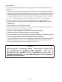
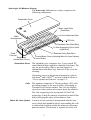
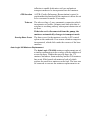
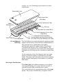
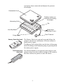
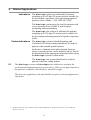
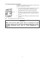
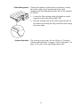
AUTO Logic™ 110, 175 & 200
AURA Logic™
User Manual
Pressure Area Care Products Division
Contents
Introduction . . . . . . . . . . . . . . . . . . . . . . . . . . . . . . . . . . . . . . . . . . . . . . . . . . . . . . . .1
About this Manual . . . . . . . . . . . . . . . . . . . . . . . . . . . . . . . . . . . . . . . . . . . . . . . 1
About Auto Logic™ . . . . . . . . . . . . . . . . . . . . . . . . . . . . . . . . . . . . . . . . . . . . . . 1
Clinical Applications . . . . . . . . . . . . . . . . . . . . . . . . . . . . . . . . . . . . . . . . . . . . . . . . .6
Indications . . . . . . . . . . . . . . . . . . . . . . . . . . . . . . . . . . . . . . . . . . . . . . . . . . . . . 6
Contra-Indications . . . . . . . . . . . . . . . . . . . . . . . . . . . . . . . . . . . . . . . . . . . . . . . 6
Installation . . . . . . . . . . . . . . . . . . . . . . . . . . . . . . . . . . . . . . . . . . . . . . . . . . . . . . . . .7
Preparing the Auto Logic systems for use . . . . . . . . . . . . . . . . . . . . . . . . . . . . . 7
Installing the Auto Logic 110, 175 or the 200 Mattress . . . . . . . . . . . . . . . . . . . 7
Installing the Pump . . . . . . . . . . . . . . . . . . . . . . . . . . . . . . . . . . . . . . . . . . . . . 10
Installing the Aura Logic Seat cushion. . . . . . . . . . . . . . . . . . . . . . . . . . . . . . . 12
Controls, Alarms and Indicators . . . . . . . . . . . . . . . . . . . . . . . . . . . . . . . . . . . . . .14
Controls . . . . . . . . . . . . . . . . . . . . . . . . . . . . . . . . . . . . . . . . . . . . . . . . . . . . . . 14
Alarms and Indicators . . . . . . . . . . . . . . . . . . . . . . . . . . . . . . . . . . . . . . . . . . . 15
Operation . . . . . . . . . . . . . . . . . . . . . . . . . . . . . . . . . . . . . . . . . . . . . . . . . . . . . . . . .16
Quick Start . . . . . . . . . . . . . . . . . . . . . . . . . . . . . . . . . . . . . . . . . . . . . . . . . . . . 16
Comfort Control . . . . . . . . . . . . . . . . . . . . . . . . . . . . . . . . . . . . . . . . . . . . . . . . 16
Power Fail Condition . . . . . . . . . . . . . . . . . . . . . . . . . . . . . . . . . . . . . . . . . . . . 17
To Disconnect the Tube-set. . . . . . . . . . . . . . . . . . . . . . . . . . . . . . . . . . . . . . . 17
Transport Mode . . . . . . . . . . . . . . . . . . . . . . . . . . . . . . . . . . . . . . . . . . . . . . . . 17
To Deflate and Store the Auto Logic Mattress. . . . . . . . . . . . . . . . . . . . . . . . . 18
To Deflate the Aura Logic Seat Cushion . . . . . . . . . . . . . . . . . . . . . . . . . . . . . 18
CPR Control. . . . . . . . . . . . . . . . . . . . . . . . . . . . . . . . . . . . . . . . . . . . . . . . . . . 19
Patient Handset and Battery Pack . . . . . . . . . . . . . . . . . . . . . . . . . . . . . . . . . . . . .20
Installing the Patient Handset . . . . . . . . . . . . . . . . . . . . . . . . . . . . . . . . . . . . . 20
Installing the Battery Pack . . . . . . . . . . . . . . . . . . . . . . . . . . . . . . . . . . . . . . . . 20
Battery Storage and Disposal . . . . . . . . . . . . . . . . . . . . . . . . . . . . . . . . . . . . . 21
Checking the Status of the Battery Pack . . . . . . . . . . . . . . . . . . . . . . . . . . . . . 22
Charging the Battery Pack. . . . . . . . . . . . . . . . . . . . . . . . . . . . . . . . . . . . . . . . 23
Decontamination . . . . . . . . . . . . . . . . . . . . . . . . . . . . . . . . . . . . . . . . . . . . . . . . . . .24
During Use. . . . . . . . . . . . . . . . . . . . . . . . . . . . . . . . . . . . . . . . . . . . . . . . . . . . 24
Routine Maintenance . . . . . . . . . . . . . . . . . . . . . . . . . . . . . . . . . . . . . . . . . . . . . . .25
Auto Logic System. . . . . . . . . . . . . . . . . . . . . . . . . . . . . . . . . . . . . . . . . . . . . . 25
Auto Logic Pump . . . . . . . . . . . . . . . . . . . . . . . . . . . . . . . . . . . . . . . . . . . . . . . 25
Auto Logic 110, 175 & 200 and Aura Logic Seat Cushion . . . . . . . . . . . . . . . 25
Serial Labels . . . . . . . . . . . . . . . . . . . . . . . . . . . . . . . . . . . . . . . . . . . . . . . . . . 25
Troubleshooting . . . . . . . . . . . . . . . . . . . . . . . . . . . . . . . . . . . . . . . . . . . . . . . . . . .26
Warranty and Service . . . . . . . . . . . . . . . . . . . . . . . . . . . . . . . . . . . . . . . . . . . . . . .27
(i)
Technical Description . . . . . . . . . . . . . . . . . . . . . . . . . . . . . . . . . . . . . . . . . . . . . . .28
Cover options and features . . . . . . . . . . . . . . . . . . . . . . . . . . . . . . . . . . . . . . . 31
(ii)
General Safety
Before you connect the system pump to a mains socket, read carefully all the
installation instructions in Section 3 - Installation. The system has been designed to
comply with regulatory safety standards including EN60601-1:1990/A13:1996.
Safety Warnings
• The cover of this product is vapour permeable but not air permeable and may
present a suffocation risk. It is the responsibility of the care giver to ensure that
the user can use this product safely.
• Electrical equipment may be hazardous if misused. The pump's case back should
only be removed by authorised technical personnel.
• Do not use the pump in the presence of flammable gases such as anaesthetic
agents.
• To assess suitability of safety sides for the AUTO Logic™ 175 mattress
replacement, the mattress provides a patient position equivalent to a 160mm
thick foam hospital mattress. We would therefore recommend that in most cases
safety sides of at least 380mm (160+220mm)1 above the mattress support
platform are used with this product. The AUTO Logic™ 200 mattress
replacement provides a patient position equivalent to a 175mm thick foam
hospital mattress. We would therefore recommend that in most cases safety sides
of at least 395mm (175+220mm)1 above the mattress support platform are used
with this product. However, as with all bed and mattress combinations, it is
important for the carers to make decisions on safety sides based on clinical
assessment and in line with local hospital policy.
• When assessing the suitability of safety sides for the AUTO Logic™ 110
mattress overlay, we recommend using safety side extensions due to the varying
thickness of hospital mattresses. However, as with all bed and mattress
combinations, it is important for the carers to make decisions on safety sides
based on clinical assessment and in line with local hospital policy.
• Whilst patient is unattended, safety sides should be used in line with the above
information and local hospital policy.
• Alignment of the bed frame, safety sides and the system should leave no gap
wide enough to entrap a patient's head or body. Care should be exercised to
prevent occurrence of gaps by compression or movement of the mattress. Death
or serious injury may occur.
Due to the inherently lower flame retardancy of the high performance eVENT® 2
fabric, it is NOT suitable for use in the homecare environment.
1. IEC 601-2-38 states that there must be a minimum clearance of 220mm between the top of the safety sides
and the top of the mattress when the bed is flat and the mattress uncompressed.
2. eVENT® is a registered trademark of BHA Technologies Inc.
(iii)
Precautions
For your own safety and the safety of the equipment, always take the following
precautions:
• Placing extra layers between the patient and the mattress/seat cushion potentially
reduces the benefits provided by the mattress/seat cushion and should be avoided or
kept to a minimum. As part of sensible pressure area care, it is advisable to avoid
wearing clothing which may cause areas of localised high pressure due to creases,
seams, etc. Placing objects in pockets should be avoided for the same reason.
• Keep the pump away from sources of liquids and do not immerse in water.
• Do not expose the system, especially the mattress/seat, to naked flames, such as
cigarettes etc.
• Do not store the system in direct sunlight.
• Switch off the electrical supply to the pump by disconnecting the pump from the
mains socket before cleaning and inspection.
• Do not use hypercarbonate or phenolic based cleaning solutions.
• Ensure the system is clean and dry prior to use or storage.
• Never use sharp objects or electrically heated under blankets on or under the system.
• Store the pump and mattress/seat in the protective bags supplied.
• Only the pump and mattress/seat combination as indicated by Huntleigh Healthcare
should be used. The correct function of the product cannot be guaranteed if the
incorrect pump and mattress/seat combinations are used.
Caution
Electromagnetic compatibility (EMC). This product complies with
the requirements of applicable EMC Standards. The use of
accessories not specified by the manufacturer may result in
increased emissions by, or decreased immunity of, the equipment,
affecting its performance
(iv)
1. Introduction
About this Manual
This manual is your introduction to the Auto Logic™
Dual Mode support systems and the Aura Logic™ seat
cushion. Use it to initially set up the mattress or seat
cushion, keep it as a reference for day-to-day routines
and as a guide to maintenance.
About Auto Logic™
The Auto Logic systems comprise of a mattress
replacement, overlay or seat cushion, all operated by the
same pump. The pump incorporates Self Set
Technology (SST), which adjusts air pressure every
10 mins for the alternating mode and 20 mins for the
Constant Low Pressure (CLP) mode to suit the Body
Mass Index (BMI) and position of the patient. Both
support systems can be used on standard hospital and
domestic beds.
Auto Logic Pump
The Auto Logic pump comprises of a moulded case with
non slip feet on the base and rear and integral hanging
brackets.
The controls are situated on the top of the pump and a
sophisticated alarm system differentiates between
normal operation and genuine system faults. If an alarm
situation is detected an indicator will illuminate on the
top and front of the pump and an audible warning will
sound.
Control Panel
Power and Alarm
Indicators
Hanging Brackets
Patient Handset Socket
1
Auto Logic 110 Mattress Overlay
The Auto Logic 110 mattress overlay comprises the
following components:
Detachable Cover
3 Static Head Cells
(Dark Blue)
Cover Attachment Zips
Cable
Management
CPR Unit
2 Standard Cells (Dark Blue)
10 Side Supporting Cell-in-Cells
(Light Blue)
Fixed
Tube-set
5 Standard Cells (Dark Blue)
Serial Label
(Inside Base Cover)
Detachable Cover
Overlay Base Cover (Including Micro Air Loss System)
Corner Straps
The standard cover comprises of a 2-way stretch PU
coated knitted fabric zipped to a durable nylon base. The
zips are protected by flaps to prevent ingress of
contaminants and allow easy removal of the cover for
cleaning.
Alternative covers with advanced properties, such as
Advantex® and eVENT®, are also available (Refer to
“Cover options and features” on page 31).
Cells
The mattress comprises of 20 polyurethane (PU) cells
providing support to the user in either Alternating or
Constant Low Pressure modes. The cells are slightly
curved to reduce patient movement down the mattress.
The side supporting cells incorporate Cell-in-Cell
technology to help the transfer of patients on and off the
bed by keeping the edges of the mattress firm.
Micro Air Loss System
A micro air loss system is incorporated into the base
cover which de-humidifies the air surrounding the cells
to reduce heat build up within the mattress and ensure
patient comfort. This system is separate from the cell
2
inflation to enable both micro air loss and patient
transport modes to be incorporated into the mattress.
CPR function
A CPR (Cardio-Pulmonary Resuscitation) control is
positioned at the head end of the mattress to allow the air
to be evacuated in under 10 seconds.
Tube-set
The tube-set has a 3-way pneumatic connection which
incorporates a flexible, compact anti-kink tube that is
resistant to crushing and any subsequent obstruction of
air flow.
If the tube-set is disconnected from the pump, the
mattress automatically changes to transport mode.
Overlay Base Cover
The base cover for the mattress overlay is PU coated
nylon on the underside. Four corner retention straps are
incorporated, which slide under the corners of the base
mattress.
Auto Logic 200 Mattress Replacement
The Auto Logic 175 & 200 mattress replacements are of
a similar construction to the overlay with the addition of
a non-slip base. Within the non-slip base, the 175
mattress includes a foam underlay and the 200 mattress
has an air filled zoned sub-mattress both of which
replace the need for a mattress on the bed. The base can
be removed to convert the mattress replacement to an
3
overlay, see your Huntleigh representative for more
information.
Detachable Cover
3 Static Head Cells
(Dark Blue)
Cover Attachment Zips
Cable
Management
CPR Unit
2 Standard Cells (Dark Blue)
Fixed Tube-set
Securing Straps
Air Sub-Mattress
(200 Only)
10 Side Supporting Cell-in-Cells
(Light Blue)
5 Standard Cells (Dark Blue)
175 - Non-slip base including foam underlay
200 - Air Filled Zoned Sub-Mattress (Non-Slip)
The Sub-Mattress provides an integral constant pressure
support which removes the need for a standard mattress.
The pressure in the central zone of the pad is
automatically adjusted in line with the Alternating /
Constant Low Pressure (CLP) of the mattress. The
pressure in the perimeter zone of the pad is maintained
at a higher level to help transfer of patients on and off the
bed.
On the underside of the Sub-Mattress there are eight
straps to attach the mattress replacement to the bed
frame. The straps can be moved to any of the 10 anchor
points to allow attachment of the mattress to different
bed frames.
Aura Logic Seat Cushion
The Aura Logic seat cushion comprises of a pressure
relieving alternating cell system and can be used on
standard hospital and normal domestic chairs.
The seat cushion can be operated using any of the Logic
pumps. The pumps automatically recognises which
4
system has been connected and adjusts the pressure
accordingly.
Detachable Cover
Deflation Valves (on
underside for packing
& storage)
Alternating Cells
Zip
Non-Slip Base
Serial Label
(Inside Base Cover)
Fixed Tube-set
Fixing Straps
Battery Pack (Optional)
The Battery Pack is an optional extra and allows the
pump to operate for a minimum of 8 hours without a
mains power supply.
The Battery Pack easily slides onto the base of the pump
and will recharge itself when the pump is operating from
the mains power supply.
Patient Handset
(Optional)
The Patient Handset is an optional extra and gives the
patient control over the comfort settings of the mattress
and also enables the patient to mute the alarm.
5
2. Clinical Applications
Indications
The Auto Logic systems are indicated for patients
weighing up to 180 kgs (28 stones) and are suitable for
the prevention of pressure ulcers and management of
pressure ulcers (Grade 1, 2 & 3 EPUAP 1999)1.
The Auto Logic systems may be used for patients with
severe pressure ulcers (Grade 4) with frequent
monitoring and repositioning.
The Aura Logic seat cushion is indicated for patients
weighing up to 180 kgs (28 stones) and is suitable for
the prevention and management of all grades of pressure
ulcers.
Contra-Indications
The Auto Logic systems in both alternating and
Constant Low Pressure modes should not be used for
patients with unstable spinal fractures.
In the case of patients with other unstable fractures,
where a moving surface can be harmful, advice should
be obtained from the appropriate physician before using
the Auto Logic system in either mode.
The Aura Logic seat system should not be used for
patients with poor sitting balance.
The Auto Logic systems and Aura Logic seat cushion are an aid to the
prevention and management of pressure ulcers. If there is no improvement in
the patient's condition, clinical advice should be sought.
The above are guidelines only and should not replace clinical judgement or
experience.
1. European Pressure Ulcer Advisory Panel (1999), Guidelines on Treatment of Pressure Ulcers EPUAP
Review 1(2):31-33.
6
3. Installation
Preparing the Auto Logic systems for use
The system is very simple to set up using the following
guidelines:
1. Remove the system from the packaging. You
should have the following items:
• Auto Logic pump including mains power cord and
hanging brackets.
• Either the Auto Logic 110 mattress overlay, the
Auto Logic 200 mattress replacement or the
Aura Logic seat cushion, which all have integral
tube-sets.
• Cover.
• Patient Handset (optional).
• Battery Pack (optional).
Installing the Auto Logic 110, 175 or the 200 Mattress
Auto Logic 110
Mattress Overlay
If you have the Auto Logic 110 mattress overlay system,
it should be installed as follows:
1. Place the overlay on top of the base mattress, with
the tube-set located near the foot end of the bed and
the CPR at the head end. The cells of the mattress
must be uppermost.
Caution
Do not use the Auto Logic 110 mattress overlay directly on the bed
frame.
7
2. Secure the overlay to the base mattress by placing
and tightening the four long straps under the
corners of the base mattress.
Auto Logic 175 or 200
Mattress Replacement
If you have the Auto Logic 175 or 200 mattress
replacement system, it should be installed as follows:
1. Remove the existing mattress from the bed frame
and check that there are no protruding bed springs
or sharp objects on the bed frame surface.
2. Unroll the mattress onto the bed frame and ensure
that the tube-set is located near the foot end of the
bed and the CPR at the head end. The cells of the
mattress must be uppermost.
3. Attach the mattress to the bed frame using the 8
fastener straps.
The 8 fastener straps can be moved to any of the 10 anchor points on the base
of the mattress replacement. This allows for attaching the mattress to
different types of bed frame.
If the bed can be profiled to any position (i.e. raised or lowered), attach the
mattress to the movable parts of the bed only.
8
To Complete the Mattress Installation
Complete the installation of the mattress overlay or the
mattress replacement as follows:
1. If not already fitted, place the protective cover over
the mattress. Ensure that the Huntleigh logo is
uppermost and at the foot end of the mattress.
“Clic
k”
2. Zip the cover onto the mattress starting from the
head end and taking care not to trap any material in
the zip.
3. Ensure that the CPR unit is clicked into the closed
position.
The CPR must be accessible at all times.
WARNING
Make sure that the mains power cable is positioned to avoid
causing a hazard and is clear of moving bed mechanisms or other
possible entrapment areas. Refer to “Cable Management” on
page 11.
9
Installing the Pump
The pump should be installed as follows:
1. Position the pump, feet down, on any convenient
horizontal surface or alternatively suspend from the
bed foot rail by means of the swing out hooks.
2. Ensure that the mattress/seat tube-set is not
"kinked" or twisted and connect it to the pump until
it clicks into place. Ensure that the tube-set is
securely connected to the pump.
3. Insert the mains power plug into a suitable mains
power socket.
”
ick
“Cl
Battery Pack
Patient Handset
If you have a battery pack, refer to “Installing the
Battery Pack” on page 20.
If you have a Patient Handset, refer to “Installing the
Patient Handset” on page 20.
10
Cable Management
If using the mattress replacement or mattress overlay,
the power cable can be positioned in the cable
management flap running down the side of the mattress
as follows:
1. Locate the flap running along the mattress on the
opposite side to the tubeset and CPR.
2. Run the straight part of the cable along the side of
the mattress securing the flap round the cable using
the press studs.
System Operation
The system is now ready for use. Refer to “Controls,
Alarms and Indicators” on page 14 and “Operation” on
page 16 for day-to-day operating instructions.
11
Installing the Aura Logic Seat cushion
The system should be installed as follows:
1. Check that there are no sharp objects on the chair
which may puncture the cushion.
2. Place the cushion on top of the chair surface. From
a standing position in front of the chair and facing
it, ensure that:
• The cells are uppermost.
• The tube-set appears from the front right corner of
the cushion.
• The cells in the seat cushion are in a horizontal
position across the chair, with the ‘V’ shape
pointing towards the front.
Cautions
• Do not use the Aura Logic seat cushion without a foam cushion
beneath it.
• Always use the Aura Logic seat cushion with the protective top
cover.
• Always use the Aura Logic seat cushion in the correct
orientation.
• Avoid trailing cables - ensure that cables and tubing are
positioned beneath the chair to avoid causing a hazard.
3. Secure the seat cushion to the chair by using the
fixing straps as shown in the following illustrations.
12
4. If the chair is of the open sided construction, then
fix the cushion as shown below:
5. If the chair is of the closed side type with a
removable seat cushion, fix the seat cushion as
shown below:
6. If the chair is of the closed side type with a nonremovable seat cushion, then security will rely on
the anti-slip base material of the seat cushion.
7. Place the protective cover over the seat cushion and
ensure that the Huntleigh H and the orientation
icon, printed on the cover, are uppermost and at the
front of the seat.
8. Zip the cover onto the seat cushion, taking care not
to trap any material in the zip.
9. Connect to the Auto Logic pump, refer to page 10.
13
4. Controls, Alarms and Indicators
Controls
Wait Indicator
Run/Standby
Low Pressure Indicator
Comfort Controls
Alarm Mute
Constant Low
Pressure Mode (CLP)
Battery Low Indicator
Service Indicator
Run/Standby Button
Power Fail Indicator
Pressing the Run/Standby button will activate the pump.
The green indicators on the control panel and the front
of the pump will illuminate when the pump is on.
To switch the pump to Standby, the button must be
pushed for 2 seconds. This prevents accidental
operation.
Alarm Mute
During an alarm condition (except Power Fail Alarm),
the sound of the alarm can be muted by pressing this
button. The yellow indicator will then remain on but the
alarms will be muted for 15 minutes or until the alarm
condition has been corrected.
This can be controlled using the Patient Handset
(optional).
Constant Low
Pressure (CLP) Mode
Selects the Constant Low Pressure (CLP), nonalternating mode. The orange indicator will illuminate
when the pump is in this mode.
When the alternating mode (default) is selected, the
orange indicator will be switched off.
14
Comfort Control
Two buttons control the relative firmness/softness of the
mattress/seat cushion for patient comfort.
The pressure setting is indicated by the yellow indicator
to the left of the buttons.
This can also be adjusted using the Patient Handset
(optional).
Alarms and Indicators
Wait Indicator
The yellow Wait indicator is illuminated when the
mattress/seat is being inflated. The indicator will remain
illuminated until the mattress/seat has been fully
inflated.
Low Pressure Indicator
The red Low Pressure indicator is illuminated whenever
the pump detects low pressure within the mattress/seat.
An audible alarm will sound unless cancelled by the
mute button.
The indicator will extinguish once normal pressure is
reached.
See “Troubleshooting” on page 26 for possible causes of Low Pressure.
Battery Low Indicator
The yellow Battery Low indicator will illuminate 2
hours before battery failure.
1 hour before battery failure, the pump will default to
Constant Low Pressure (CLP) mode, an audible alarm
will sound and the yellow indicator will flash.
Power Fail Indicator
The red Power Fail indicator will illuminate when a
mains power failure has been detected and no battery
backup is available. An audible alarm will sound until
power is resumed or the pump is switched off using the
run/standby button.
If a Power Fail condition arises and no battery is
connected, disconnect the tubeset from the pump. This
will put the mattress into transport mode (Refer to
page 17).
Service Indicator
The yellow Service indicator will illuminate and remain
on after a set number of running hours. This indicates
that the pump is ready for a service. The pump will
continue to function normally even when the service
indicator is illuminated.
If the yellow Service indicator flashes, the pump has
detected an internal fault and a Service Engineer should
be called.
15
5. Operation
These instructions cover day-to-day operation of the system. Other operations, such
as maintenance and repair, should only be carried out by suitably qualified
personnel.
Quick Start
Run/Standby
Before using any of the Auto Logic mattress or seat
systems make sure it has been installed correctly in
accordance with “Installation” on page 7 and ensure that
the CPR unit on the mattress is clicked into the closed
position.
1. When the Auto Logic pump is switched on at the
mains supply or a battery pack is connected, an
audible beep will sound and a self-diagnostic check
will run for approximately 10 seconds. When the
check is complete a second audible beep will sound
and the pump is ready for use.
2. Press the Run/Standby button on the control panel
of the pump. The Run/Standby and Wait indicators
will illuminate together with the comfort indicator
and the green light on the front of the pump.
3. Allow approximately 7 minutes for the mattress
overlay, 15 minutes for the mattress replacement or
2-3 minutes for the seat to inflate fully.
The amber Wait indicator will go off once the mattress/seat is fully inflated.
4. Place a bed sheet over the mattress and tuck in
loosely. Ensure that the CPR unit is clearly visible
at the head end of the bed.
Once the patient is on the mattress, the pump will automatically sense and
adjust the pressure in the cells using Self Set Technology (SST) to support the
patient.
Comfort Control
The mattress/seat cell pressure can be manually adjusted
for patient comfort using the buttons on the pump
control panel.
This can also be adjusted using the comfort control
buttons on the Patient Handset panel (optional).
16
Power Fail Condition
If a Power Fail condition arises and no battery is
connected, disconnect the tubeset from the pump. This
will put the mattress into transport mode and will
support the patient for up to 12 hours. Once power is
resumed, re-connect the tubeset to the pump.
To Disconnect the
Tube-set
To disconnect the tube-set at any time, push the button
down and pull the tube-set connector away from the
pump.
This will put the mattress into Transport Mode and will
not deflate the mattress. To deflate the mattress
Refer to page 18.
Transport Mode
To transport a patient using the Auto Logic mattress,
disconnect the tube-set from the pump. This will
automatically switch the mattress into transport mode.
The patient will remain supported by the mattress for up
to 12 hours.
To resume normal operation, simply reconnect the tubeset and run the pump.
17
To Deflate and Store the Auto Logic Mattress
To deflate the mattress:
1. Disconnect the tube-set from the pump.
2. Activate the CPR control to deflate the mattress.
To store the mattress
Following deflation:
1. Bring the tubeset over the mattress to lie parallel to
the foot end of the mattress.
2. Roll the mattress from the foot end toward the CPR
connector at the head end of the mattress.
2
1
To Deflate the Aura Logic Seat Cushion
To deflate the seat cushion:
1. Disconnect the tube-set from the pump.
2. Depress the 2 valves on the underside of the seat
cushion.
18
CPR Control
IMPORTANT
IN THE EVENT OF CARDIAC ARREST
In the event of a patient suffering cardiac arrest and CPR
needing to be administered:
To activate CPR
To reset CPR
Press the two CPR release buttons simultaneously.
Push the front of the CPR unit until it clicks into place.
k
“Clic
19
”
6. Patient Handset and Battery Pack
Installing the Patient Handset
If you have a Patient Handset for the pump, install it as
follows:
1. Connect the Patient Handset into the socket on the
side of the pump.
2. Hang the Patient Handset on the bed frame within
easy reach of the patient.
The Patient Handset can be used to control the comfort setting and to mute
the alarm.
Alarm Mute Control
Comfort Control
Patient Handset
Connector
Patient Handset
Installing the Battery Pack
Install the battery pack to the pump as follows:
1. Remove the battery socket cover from the base of
the pump.
2. From the front of the pump, slide the battery pack
over the guides on the base of the pump and click
into place.
20
3. To remove the battery pack, depress the reset/status
latch at the rear of the unit and slide the battery
pack out from the base of the pump. Replace the
battery socket cover on the base of the pump.
Battery Socket Cover
Reset/Status Latch
Battery Pack
Battery Storage and
Disposal
If the device is not to be used for an extended period,
remove and store the battery pack. If the battery packs
are to be put into long term storage they should be
recharged at least once every 3-6 months. Faulty battery
packs should be sent back to a Huntleigh service centre
for recycling.
21
Checking the Status of the Battery Pack
Battery Label
Jack Socket Polarity
LED 1
LED 2
80-100% Charge
Battery Pack OK
Battery Pack
needs recycling
30-80% Charge
<30% Charge
Battery Pack
Fault
Press Reset / Status Latch
To check the battery pack status
To check the status of the battery pack:
1. Remove the battery pack from the pump unit.
2. Press the Reset/Status Latch, this will activate the 2
LEDs on the top of the battery.
If the battery pack is not on charge the LEDs will display one of the following
conditions:
LED 1
LED 2
Green
Green
Green
Green
Red
The Battery Pack is OK. It has > 80% charge.
The Battery Pack is OK. It has between 30-80% charge.
The Battery Pack is OK. It has < 30% charge.
Green
Red
Battery Status
Green
The Battery Pack needs recycling*. It has between 30-80% charge.
The Battery Pack needs recycling*. It has < 30% charge.
The Battery Pack has an error.
Red
The Battery Pack is flat or has an error. Try recharging.
22
If the battery pack is on charge, via the optional battery charger, the LEDs will
display one of the following conditions:
LED 1
Green
LED 2
Battery Status
The Battery Pack is OK. It is fully charged.
Green
The Battery Pack is charging.
Green
Red
Red
The Battery Pack needs recycling*. The Battery is charging.
Green
The Battery has an error. This could be a temporary fault due to
adverse operating temperature.
The Battery has an error.
* Once the battery pack has entered the ‘recycling’ mode it will never show that the
battery is fully charged (Note: This does not indicate a fault condition).
Charging the Battery Pack
The battery pack is automatically recharged whenever it is connected to a pump
which is connected to an AC outlet. Alternatively the battery pack can be recharged
away from the pump by plugging into the battery charger as shown below.
It is normal for the battery pack and charger to get warm during use.
Avoid charging the battery near source of heat or in direct sunlight.
To ensure the long term performance of the battery pack, periodically run the pump
using the battery pack until the pump switches off. This will fully discharge the
battery pack. Fully recharge the battery pack before further use.
23
7. Decontamination
The following guidelines have been established in accordance with good infection
control practice. Should you have any questions regarding cleaning or if you require
further information please contact our service centre.
Caution
Gloves and protective clothing should always be worn when
carrying out decontamination procedures.
WARNING
Switch off the electrical supply to the pump and disconnect the
power cord from the mains supply before cleaning and inspection.
During Use
To clean
To disinfect
The mattress, seat cushion, pump, tube-set and other
ancillary parts should be cleaned weekly and in between
each patient use using a disposable cloth soaked in mild
detergent and warm water. Do not use abrasive
compounds or pads. The user should avoid immersing
electrical parts in water during the cleaning process.
All parts can be wiped down with sodium hypochlorite or
NaDCC solution at 1000ppm of available chlorine
following the cleaning procedure.
Using other disinfectants may cause damage to the
products. If you wish to use disinfectants recommended in
local infection control guidelines, please contact your
Huntleigh Healthcare representative.
Do not use Phenol or Quarternary Ammonium Compound
(QAC) based cleaning solutions as these will damage the
surface coating.
Laundering
The mattress/seat top covers can be easily unzipped for
complete removal to allow laundering at 65°C for 10
minutes or 80°C for 3 minutes to achieve thermal
disinfection. This complies with HSG (95) 18 Hospital
Laundry arrangements for used and infected linen (UK)
1995.
DO NOT TUMBLE DRY COVERS ABOVE 50°C.
Further Information
For further detailed decontamination guidance, consult
Huntleigh Healthcare Infection Control Procedures Policy Guidelines.
24
8. Routine Maintenance
Auto Logic System
Maintenance
Servicing
The equipment has been designed to be virtually
maintenance-free between service periods.
Huntleigh Healthcare will make available on request
service manuals, component parts lists and other
information necessary for Huntleigh Healthcare trained
personnel to repair the system.
Auto Logic Pump
General Care,
Maintenance and
Inspection
Check all electrical connections and power cord for
signs of excessive wear.
In the event of the pump being subjected to abnormal
treatment, e.g. immersed in water or dropped, the unit
must be returned to an authorised service centre.
Auto Logic 110, 175 & 200 and Aura Logic Seat Cushion
General Care
Remove the top cover and inspect for signs of wear or
any tears.
Check all zips are secure.
Check integrity of all connectors, including cell to
manifold connections.
Ensure all cell fasteners are correctly connected to the
mattress base sheet and are not loose or damaged.
Serial Labels
Pump
The serial number for the pump is on the label on the
back of the pump case.
Mattress
The mattress serial label can be found just inside the
base cover above the tubeset, refer to the illustration on
page 2.
Seat Cushion
The seat cushion serial label can be found just inside the
front of the base cover, refer to the illustration on page 4.
25
9. Troubleshooting
The following table provides a troubleshooting guide for the Auto Logic and
Aura Logic systems in the event of malfunction.
Indicator
Possible Cause
Remedy
LOW PRESSURE and WAIT
The pump is inflating the
mattress/seat.
Both indicators will extinguish
when operating pressure is
reached.
CPR not fully closed.
Close CPR unit.
The tube-set is not connected
properly.
Check the tube-set connector
and ensure it is securely fitted to
the pump.
CPR not fully closed.
Close CPR unit.
There is a leak in the system.
Call service engineer.
Power has been removed from
the pump.
Re-apply power or switch the
pump off.
LOW PRESSURE
POWER FAILURE
If the fully charged battery pack
is fitted the pump will continue to
operate for a minimum of 8
hours.
BATTERY LOW
Low battery life.
Install a fully charged battery
pack.
Charge the battery by using
mains power supply to run the
pump.
SERVICE (ON)
Pump needs a service.
Call service engineer.
To find the serial numbers for the
pump, mattress or seat refer to
“Serial Labels” on page 25.
SERVICE (FLASHING)
Pump has detected an internal
fault.
26
Switch the pump off and call
service engineer.
10. Warranty and Service
Huntleigh Healthcare's standard terms and conditions apply to all sales. A copy is
available on request. These contain full details of warranty terms and do not limit the
statutory right of the consumer.
Huntleigh Healthcare recommend that the Auto Logic and Aura Logic systems
should be serviced every 2 years.
For service, maintenance and any questions regarding this, or any other Huntleigh
Healthcare product, please contact:
Huntleigh Healthcare Ltd
310-312 Dallow Road
Luton
Bedfordshire, LU1 1TD
Tel : +44 (0) 1582 413104
Fax : +44 (0) 1582 459100
27
11. Technical Description
Auto Logic Pump
630001
Supply Voltage:
90-230 Vac
Supply Frequency:
50-60 Hz
Electrical Rating:
50 VA - Mains powered, no battery pack connected
85 VA - Mains powered
Battery pack connected (charging)
Size:
Length:
375 mm
Height:
280 mm
Depth:
125 mm
Weight:
2.75 kg
Fuse ratings:
Plug:
Pump:
5A to BS1362
Internal Fuse T3.15 AH 250V
UK and Euro Electrical Safety Standards
Complies with:
EN 60601-1:1990/A13:1996
Degree of protection
against electric shock:
Class II, Type BF
Mode of operation:
Continuous
(Internally powered)
Pump Symbols
Alternating Current
Type BF
Double Insulated
Refer to the User Manual
SN:
Serial Number
Battery Pack
BBP600
Size:
242 x 37 x 118 mm
28
Weight:
0.8 kg
Electrical Rating:
DC 13.8V 4Ah (NiMH)
Battery Symbols
Do not dispose of in a dustbin (Recycle)
Recycle
Environmental Conditions
Operating (Pump & Battery Pack)
Temperature range:
+10°C to +40°C
Relative humidity:
30% to 75%
Atmospheric pressure
700hPa to 1060 hPa
Storage (Pump)
Temperature range:
-40°C to +70°C
Relative humidity:
10% to 100% (non-condensing)
Atmospheric pressure:
500 hPa to 1060 hPa
Storage (Battery Pack)
Temperature range:
-10°C to +30°C
Relative humidity:
30% to 75%
Atmospheric pressure:
500 hPa to 1060 hPa
Environmental Protection:
Please dispose of this unit in accordance with local
regulations.
Auto Logic 110 mattress
Height:
115 mm (4.5")
Cell Material:
Polyurethane
Auto Logic 175 mattress
Height:
175 mm (7")
Cell Material:
Polyurethane
Foam underlay size:
2032 x 838 x 63.5 mm (80"x 33" x 2.5")
Base Material:
PU Laminate
29
Auto Logic 200 mattress
Height:
205 mm (8")
Cell Material:
Polyurethane
Air-filled sub-mattress size:
2030 x 860 x 90 mm (80"x 34" x 3.5")
Base Pad Material:
PU Laminate
Mattress Size Information
Part No.
Description
Spare Cover
Length mm
Width mm
PXA001ADV
AUTO Logic 110 (Advantex)
PXA082
2030 (80")
860 (34")
PXA001DAR
AUTO Logic 110 (Dartex)
PXA080
2030 (80")
860 (34")
PXA001EVE
AUTO Logic 110 (eVENT)
PXA084
2030 (80")
860 (34")
PXA201ADV
AUTO Logic 110 Narrow (Advantex)
PXA282
2030 (80")
780 (30")
PXA201DAR
AUTO Logic 110 Narrow (Dartex)
PXA280
2030 (80")
780 (30")
PXA201EVE
AUTO Logic 110 Narrow (eVENT)
PXA284
2030 (80")
780 (30")
PXB001ADV
AUTO Logic 200 (Advantex)
PXB082
2030 (80")
860 (34")
PXB001DAR
AUTO Logic 200 (Dartex)
PXB080
2030 (80")
860 (34")
PXB001EVE
AUTO Logic 200 (eVENT)
PXB084
2030 (80")
860 (34")
PXB201ADV
AUTO Logic 200 Narrow (Advantex)
PXB282
2030 (80")
780 (30")
PXB201DAR
AUTO Logic 200 Narrow (Dartex)
PXB280
2030 (80")
780 (30")
PXB201EVE
AUTO Logic 200 Narrow (eVENT)
PXB284
2030 (80")
780 (30")
PXB005ADV
AUTO Logic 175 (Advantex)
PXB182
2030 (80")
860 (34")
PXB005DAR
AUTO Logic 175 (Dartex)
PXB180
2030 (80")
860 (34")
PXB005EVE
AUTO Logic 175 (eVENT)
PXB184
2030 (80")
860 (34")
30
Cover options and features
Feature
Standard Cover
Advantex™
eVENT® Fabric *
Moisture vapour
permeable
Yes
Yes
12 x higher
Air permeable
No
No
Yes
Low friction
Yes
18% lower
20% lower
Water resistant /
repellent
Yes
Yes
Yes
Infection Control
Bacteriostatic,
fungistatic, antimicrobial
Bacteriostatic,
fungistatic, antimicrobial
INERT MATERIAL does
not support bacterial
growth
Fire retardant
BS 7175: 0,1 & 5
BS 7175: 0,1 & 5
BS EN ISO 12952-1
ONLY
2 way stretch
Yes
Some
No
Cleaning conditions
Removable cover,
washable at 80°C
Removable cover,
washable at 80°C
Removable cover,
washable at 80°C
Life span
50 Wash Cycles
50 Wash Cycles
15 Wash Cycles
Application area
Acute and Homecare
Acute and Homecare
Acute ONLY
*Due to the inherently lower flame retardancy of the high performance eVENT® fabric, it is NOT suitable
for use in the homecare environment.
Aura Logic Seat Cushion
PXS001
Length:
470 mm
Width:
455 mm
Height:
50 mm
Cell Material:
Polyurethane
31
Cleaning Symbols
Wash at 80°C (176°F)
Do not iron
Do not use phenol or QAC based cleaning solutions
Do not tumble dry above 50°C.
Wipe surface with damp cloth
Use solution diluted to 1000 ppm
32
United Kingdom
United States of America
Huntleigh Healthcare Ltd
310-312 Dallow Road, Luton
Bedfordshire, LU1 1TD
T: +44 (0)1582 413104
F: +44 (0)1582 459100
Huntleigh Healthcare L.L.C.
40 Christopher Way
Eatontown
New Jersey 07724-3327
T: +1 (732) 578-9898 or
+1 (888) 223-1218
F: +1 (732) 578-9889
Australia
Nederland
Huntleigh Healthcare Pty Limited
PO Box 330
Hamilton Hill
Western Australia 6963
T: +61 8 9 337 4111
F: +61 8 9 337 9077
Huntleigh Healthcare BV
Antennestraat 45
1322 AH Almere
T: +31 (0)36 533 55 88
F: +31 (0)36 547 50 75
België / Belgique / Belgien
New Zealand
Huntleigh Healthcare NV SA
Evenbroekveld 6
B-9420 Erpe-Mere
T: +32 (0) 53 60 73 80
F: +32 (0) 53 60 73 81
Huntleigh Healthcare Ltd
Unit 6/38 Eaglehurst Road
Ellerslie, Auckland, New Zealand
T: +64 9 525 2488
F: +64 9 525 2433
Deutschland
South Africa
HNE Healthcare GmbH
Im Hülsenfeld 19
D-40721 Hilden
T: +49 (0)2103/97 11-0
F: +49 (0)2103/97 11-80
Huntleigh Africa (Pty) Ltd
Willem Cruywagen Avenue
Stand 120, Klerksoord
Pretoria, South Africa
T: +27 12 542 4680
F: +27 12 542 4982
Danmark
Sverige
Huntleigh Healthcare A/S
Vassingerødvej 52
DK-3540 Lynge
T: +45 4 913 8486
F: +45 4 913 8487
Huntleigh Healthcare AB
Box 30012
S-200 61 Limhamm
T: +46 (0)40 36 03 50
F: +46 (0)40 49 43 75
España
Switzerland
Huntleigh Healthcare SL
Avda. de la Industria, 32-2ª
28108 - Alcobendas - Madrid
T: +34 902 108 530
F: +34 902 108 532
HNE Médical
5 Route de Fribourg
1723 MARLY
Switzerland
T: +41 (0) 26 436 2059
F: +41 (0) 26 436 2060
France
HNE Médical SA
451 Chemin de Champivost
BP20, 69579 Limonest Cedex
T: +33 (0)4 78 66 62 66
F: +33 (0)4 78 66 62 67
© Huntleigh Healthcare Limited 2003
630900EN_05