1
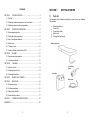
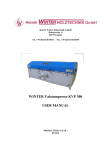
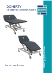
Lullaby
INTRODUCTION
ALTERNATING DYNAMIC PRESSURE THERAPY SYSTEM
Thank you for choosing a Sidhil Lullaby Alternating Dynamic Pressure
Therapy System. This user manual should be read carefully before you
use your mattress system as it contains important information regarding
safe operation and maintenance in order to provide long lasting and reliable
service.
Please ensure that you understand all the instructions, if you have any
questions concerning the operation and maintenance of the mattress
system please contact your supplier who will provide you with expert
professional advice.
The Lullaby Alternating Dynamic Pressure Therapy System is intended to
provide comfort and pressure relief to patients vulnerable to pressure
damage. It is designed for use on the Sidhil Inspiration Cot. Ideally,
patients allocated to this system will have some degree of independent
mobility or can be repositioned according to individual needs.
The standard system DYN/TRIO/LULL incorporates an alternating mattress
with static head section. An optional system DYN/TRIO/LULL/RP
incorporates an alternating mattress with alternating head section
The maximum patient weight limit is 160kg (25 stone).
WARNING
Misused electrical equipment can be hazardous.
Accessories that have not been approved or designed for use
with the system should not be used.
This electrically operated system should not be used in the
presence of flammable gases or in operating theatres.
This product is not recommended for carrying patients during
emergency evacuation.
In line with our policy of continuous improvement we welcome any
suggestions that could lead to product improvement.
This product is manufactured to comply with the essential
requirements of the Medical Devices Directive 93/42 EEC
User Instructions
www.sidhil.com
1
Contents
SECTION 1
GETTING STARTED .......................................................... 3
1.1 Parts list ........................................................................................... 3
1.2 Setting up mattress and power unit on a bed frame ........................ 4
1.3 Switching system on and basic operation........................................ 6
SECTION 2
POWER UNIT OPERATION............................................... 8
2.1 Normal operating mode ................................................................... 8
2.2 Setting the optimum pressure .......................................................... 8
SECTION 1
1.1
GETTING STARTED
Parts list
The transport carton contains everything you need to use your mattress.
This includes:
Mattress and Cover
Power Unit
Power Down Alarm
Mains Lead
Storage Bag (not shown)
2.3 Use of incontinence products........................................................... 9
2.5 Static mode ...................................................................................... 9
Mattress and Cover
2.6 Transport mode.............................................................................. 10
2.7 Cardio pulmonary resuscitation (CPR) .......................................... 11
SECTION 3
ALARMS ........................................................................... 12
3.1 Power down alarm operation ......................................................... 12
3.2 Low Pressure Alarm....................................................................... 12
SECTION 4
CLEANING........................................................................ 13
Power Down
Alarm
4.1 Infection control.............................................................................. 13
4.2 Cleaning the power unit ................................................................. 13
4.3 Cleaning the mattress .................................................................... 13
SECTION 5
SIMPLE FAULT FINDING................................................. 15
SECTION 6
SERVICING ...................................................................... 16
Power Unit
Mains Lead
6.1 Routine servicing............................................................................ 16
6.2 Air filter replacement ...................................................................... 16
6.3 Spare part availability..................................................................... 16
6.4 Serial number locations ................................................................. 17
SECTION 7
TECHNICAL SPECIFICATIONS....................................... 18
WARRANTY................................................................................................ 20
2
3
1.2
Setting up mattress and power unit on a bed frame
1. Remove the existing mattress from the bed frame and inspect the bed
for any sharp areas which could damage your new mattress.
*If the bed does not have a foot board, place the power unit on the floor
with the front of the unit facing upwards. Ensure the rear of the unit is
not obstructed by carpet, rugs etc it is advisable to place the unit on a
firm surface.
Fig 2: Connecting the power unit to the mains supply
2. Remove the mattress from the packaging and place it onto the bed
frame with the air pipe and power unit at the foot end and the foot
graphic facing upwards.
Power Unit
Power Down
Alarm
Mains Lead
4. Connect the air pipes from the mattress to the power unit. Connect the
pair of pipes with turquoise colour connector ends to the corresponding
turquoise connectors on the power unit. The remaining two individual
pipes should be clipped onto their corresponding coloured connectors
on the power unit, i.e. black to black and orange to orange (see Figure
3).
Fig 3: Connecting mattress air pipes to power unit
3. Hang the power unit on the foot board of the bed*, using the wire
handles at the rear of the power unit. Connect the power down alarm to
the power unit and connect the mains lead from the power down alarm
to a suitable electrical socket outlet (see Figure 2).
4
WARNING
Ensure that the mains lead is not under tension
when connected to the power supply.
Ensure that all cables and air supply pipes are
clear of any moving parts on the bed to prevent
them becoming tangled or damaged
5
5. Ensure that the CPR valve on the mattress umbilical has the pair of
white dots aligned, as shown in Figure 4. This indicates that CPR
mode has not been activated.
1. Before switching on the power unit turn the pressure adjustment dial to
hard and set the dynamic/static rocker switch to dynamic . Switch on
the power unit by depressing the green rocker switch. The alarm light
will now be illuminated red, the normal and static light indicators
should not be illuminated (see Figure 5).
Fig 4: CPR dot orientation
Fig 5: Initial setup of the power unit
Alarm Light
Illuminated Red
Green Rocker
Switch - On
1.3
Dynamic / Static
Rocker Switch
Dynamic
Switching system on and basic operation
Read all instructions below before use:
To reduce the risk of electrocution:
Always unplug this product immediately after using
Do not use while bathing
Do not place or store product where it can fall or be pulled into a tub or
sink
Do not place in or drop into water or other liquid
Do not use a product that has fallen into water. Unplug immediately
To reduce the risk of burns, electrocution, fire, or injury to persons:
Some supervision may be necessary when used by or near children or
the physically challenged
Use this product only for its intended use as described in this manual.
Do not use attachments not recommended by Sidhil Ltd
Never operate this product if it has a damaged mains lead or plug. If it
is not working properly or if it has been dropped or damaged in any way
please contact your local authorised service personnel or Sidhil Ltd
Keep the mains lead away from warm surfaces
Never block the air filters on the power unit or place it on a soft surface,
such as a bed or a couch, where the openings may be blocked
Never drop or insert any objects into any tubing / openings
Pressure Adjustment
Dial - Hard
2. The mattress will start to inflate. This process will take approximately 40
minutes. When the mattress is fully inflated the red alarm light will go
out and the green light indicating normal operation will be lit (see Figure
6).
Fig 6: Power unit indicator light
Normal Light
Illuminated Green
3. Once inflated, ensure that the mattress is correctly position on the bed.
4. Ensure that the mattress is always covered with a loose fitting bed
sheet. Before placing a patient onto the mattress refer to Setting
the Optimum Pressure .
WARNING
This equipment is not suitable for use in the
presence of a flammable anaesthetic mixture with
air, oxygen or nitrous oxide.
Keep away from sources of heat and naked flames
6
7
SECTION 2
2.1
POWER UNIT OPERATION
Normal operating mode
In the normal operating mode the system will inflate and deflate each cell
series every 12 minutes.
The inflation pressure can be changed using the pressure adjustment dial
on the power unit; this can be varied between approximately 35mmHg and
60mmHg.
To ensure patients receive effective pressure relief the system should
always be set to the dynamic setting.
2.2
Setting the optimum pressure
When in dynamic mode all pressures will apply therapy to the user but it is
generally accepted that the higher the pressure setting the greater the
therapeutic effect, however this may have a trade off in terms of patient
comfort. The optimum setting for the patient, balancing comfort against
therapy will differ between patients.
Once the patient is in place, use the pressure adjustment dial to reach the
desired setting for patient comfort/therapy.
Having established a base-line, pressure can be increased to provide
added support for the semi-recumbent (sitting up) patient.
NOTE: Wait a minimum of 12 minutes between any pressure adjustment
and patient assessment. It will take a full cycle for the system to adjust to
the new setting.
2.3
Use of incontinence products
Incontinence products such as sheets or pads can be used with this
system. However, product performance is likely to reduce due to the patient
experiencing less pressure relief when using these aids.
If incontinence products are to be used it is recommended that regular
patient skin checks are performed to ensure skin integrity is maintained.
2.5
Static mode
The system has the capability to operate as a static inflated mattress. This
function enables nursing staff to carry out procedures on a static support
surface and/or to assess the ability of a patient to withstand a static support
surface. This is necessary to facilitate patient step down to a nonalternating product.
When selecting a lower pressure setting ensure the patient is not
bottoming out by sliding a hand under the patient s sacral area (buttocks)
when the cell is fully deflated. The patient should be lying flat on their back
in a supine position for this assessment (see Figure 7).
Fig 7: Check for bottoming out
8
9
To select static mode depress the dynamic/static switch to static , the
static light will now be illuminated amber (see Figure 8).
orange and black connectors. The two single pipes snap fit into the dual
connection pipes as shown in Figure 9.
The pressure can be adjusted to suit using the pressure adjustment dial on
the front of the power unit. The Pressure should be reduced when using the
static mode to check for a patient s suitability to tolerate a static mattress.
Fig 9: Connecting pipes for transport mode
Fig 8: Setting power unit to static mode
Static Light
Illuminated Amber
Dynamic / Static
Rocker Switch
Static
Pressure Adjustment
Dial To Suit as
Necessary
Regular patient skin checks should be performed to ensure that a static
support surface can be tolerated. Ideally patients should remain on a static
support surface for no more than 2 hours without undergoing a thorough
skin check. If the patient cannot tolerate static mode the system should be
reverted to dynamic therapy by repressing the dynamic/static switch to
dynamic . The static light will extinguish and the green normal light will
be illuminated. The system will now be operating in dynamic mode.
WARNING
There will be air loss from the system when disconnecting/connecting the
pipes for transport mode. The longer it takes to connect the air pipes
together the greater the volume of air lost. If the pressure is increased prior
to the disconnection the effect of the air loss will be reduced.
Note: the pipes should only be connected together when the mattress
needs to be moved whilst remaining inflated. If the user needs to be on a
mattress which is not alternating, static mode should always be selected
the pipes connected to the power unit.
2.7
Cardio pulmonary resuscitation (CPR)
The mattress can be quickly deflated for CPR. To begin CPR deflation,
twist the CPR valve in the direction of the arrows to align the two red dots,
as shown in figure 10. The mattress will deflate in approximately 30
seconds.
Fig 10: Activating the CPR valve
THE STATIC MODE WILL REMAIN
OPERATIONAL UNTIL THE STATIC SWITCH IS
RETURNED TO THE DYNAMIC POSITION.
WHEN IN STATIC MODE THE PATIENT MUST
BE REGULARLY CHECKED FOR SKIN
INTEGRITY.
2.6
Transport mode
The transport mode is achieved by disconnecting the four air pipes from the
power unit and then connecting them together. Disconnect the pair of pipes
with turquoise colour connectors first, then the two single pipes with the
10
If required, the mattress can be re-inflated while supporting the patient by
twisting the mattress CPR valve back to the original position with the white
dots realigned. The mattress will then re-inflate in approximately 30
11
minutes back to its original pressure setting. Note: Until the system reinflates to the desired pressure the red alarm light will be illuminated.
A persistent alarm light indicates a system fault. In this instance see the
Simple fault finding section.
SECTION 3
SECTION 4
ALARMS
4.1
3.1
Power down alarm operation
The power down alarm indicates an interruption in power supply that can
be caused by either a mains failure and/or turning off the power unit. The
alarm will produce an audible sound and/or a red flashing light. These
alarms can be selected by means of a sliding switch (see Figure 11). See
Figure 2 for plugging the power down alarm in.
4.2
Sliding Switch
Alarm Selector
Cleaning the power unit
WARNING
Disconnect the mains lead from the wall-socket before
attempting to clean the unit.
Do not immerse the power unit in water.
Pressing the reset button on the power down alarm
Restoring the power supply to the system
Reset Button
Infection control
Routine cleaning for infection control must be carried out in accordance
with your local infection control policy or regulatory body.
The alarm can/will be cancelled in one of two ways:
Fig 11: Power down alarm
CLEANING
Ensure mains lead and power unit are dry before use.
The power unit, mains lead and power down alarm can be cleaned by
wiping down with a damp cloth soaked in a 75° Sodium Hypochlorite
solution (1000 ppm available chlorine) and dried with a clean dry cloth.
The power unit is not IP rated and care should be taken that only a damp
cloth is used.
4.3
3.2
Low Pressure Alarm
The power unit is fitted with a red alarm warning light to identify low
pressure in the mattress. The alarm light will illuminate red if the pressure
within the mattress drops below the minimum level. The alarm light will
automatically reset once normal operating pressure is reached. Note: the
power unit does not have an audible alarm.
False alarms may be noticed if a patient has a gross position change or is
removed from an inflated mattress. A false alarm will reset itself in a few
minutes and should be ignored.
12
Cleaning the mattress
Before attempting to clean the mattress the top cover should be checked
for physical signs of damage that may lead to strike-through (ingress of fluid
through cover). This is achieved by unzipping the top cover and looking for
signs of staining to the white underside. Any evidence of strike-through will
require a new cover to be fitted to the system. The cover must not be
reused if strike-through is evident.
The mattress cover can be wiped down with a 75° Sodium Hypochlorite
solution, (1000 ppm available chlorine) and then dried with a clean dry
cloth. Alternatively the mattress cover can be machine washed at a
temperature not exceeding 75°C and dried either in free air or a tumble
drier on a cool setting (see Figure 12).
The cells can be cleaned by deflating the mattress, unzipping the top cover
and wiping down the deflated cells with a 75°C Sodium Hypochlorite
13
solution (1000 ppm available chlorine).
clean dry cloth before use.
Dry the cells thoroughly with a
SECTION 5
Fig 12: Mattress cover cleaning instructions
Machine Wash
at 75°
Do Not Bleach
Do Not Iron
SIMPLE FAULT FINDING
Fault
Dry Clean
Tumble Dry on
(Trichloroethylene Low Heat
Not to be Used)
There are no lights showing on the
power unit front panel
The mattress, power unit and power-down alarm may also be
decontaminated by using ETO (Ethylene Oxide) or the Draeger method.
There are lights showing on the
front panel but the mattress fails to
inflate
Mattress is not alternating
Action
1. Check that the power unit is
switched on
2. Check that the mains lead is
plugged into a working wall
socket and the wall socket is
switched on. (To ensure socket
is working plug in a lamp or other
electrical device)
3. Check that the mains lead is
plugged into the power unit
4. If none of the above work replace
fuse in the mains plug (3 Amp
230V)
1. Check the CPR valve has the
white dots aligned
2. Check that the mattress is
correctly connected to the power
unit
3. Check that all air pipe connectors
are snapped fully into place on
the power unit
4. Unzip mattress cover and check
all cells are pushed fully onto
internal air-pipes
1. Check power unit is switched on
2. Check that the dynamic/static
rocker switch is set to dynamic
3. Check mattress is not in transport
mode
If the above actions fail to rectify the problem please contact your local
authorised service personnel or Sidhil Limited.
14
15
SECTION 6
6.1
Air cells and interchangeable mattress covers can be purchased
separately.
For further information please contact the Sidhil customer service staff on
01422 233000 or email [email protected]
SERVICING
Routine servicing
Other than the air filters, there are no user serviceable items within the
power unit.
The system should be serviced annually by a qualified service technician.
This service can be supplied by Sidhil technicians or alternatively Sidhil can
provide appropriate training.
6.2
6.4
Serial number locations
The serial number of the power unit is located on the rating plate on the
rear of the housing and is contained in the white block in the middle of the
unit. The mattress serial number is located on a label inside the mattress
at the foot end just above the umbilical entry. The label is sewn into the
seam of the bottom half of the cover.
Air filter replacement
1. Switch off the power unit
2. Disconnect the mains lead and air pipes
3. Place the power unit on a flat surface with its back panel facing upwards
(Note: be sure to place a soft cloth under unit to prevent scratching)
4. Carefully remove the air filter covers, remove and discard the filters,
replace with new filters and re-fit covers (see Figure 13)
5. The power unit is now ready for use
It is recommended that the air filters are replaced annually.
Fig 13: Air filter removal
Power Unit Housing
Filter
Cover
6.3
Spare part availability
The annual service requires both air filters to be changed as well as the
compressor inlet filter. These components are available as maintenance
items. It is recommended that the compressor inlet filter is replaced by a
qualified service technician.
16
17
SECTION 7
TECHNICAL SPECIFICATIONS
Mattress
Fuse Rating
1290mm x 695mm x 100mm
(51 x 27.5 x 4 )
4kg (8.8lbs)
17
Nylon Single TPU coated
Nylon TPU coated
Coated polyamide fabric
4 x Quick release connectors
In-line twist system CPR
valve
Dimensions
Weight
Number of Cells
Cell Material
Base Material
Cover Material
Mattress Connection
CPR Mechanism
Power Unit
280mm x 140mm x 125mm
(11 x 5½ x 5 )
1.8kg (4lbs)
Dimensions
Weight
Power Rating
Electrical Safety
Classification
Mode of
Operation
Symbols
Mains Switch
Environment
(Usage &
Storage)
IP Rating
EMC
Power down Alarm
100mm x 50mm x 35mm
(4 x 2 x 1.5 )
0.12kg (0.25lbs)
Dimensions
Weight
Cycle Time
Supply Voltage
Power unit: 230V, 50Hz, 0.2A
Power down alarm: 24~250VAC, 50Hz,
0.01 - 6A
Mains plug: 3A
Power unit: 1A (x2)
12VA
Conforms to EN 60601.1:1996, UL2601 1 safety standard
Class II, no applied part
Continuous
~ Alternating current
I (On) Power connected to the mains
supply via power-down alarm
0 (Off) Power disconnected from powerdown alarm
Air humidity
30% to 75%
Ambient temperature
0°C (32°F) to
40°C (I04°F)
IPXO
This equipment complies with EMC
requirements. If effects are noticed the
affected equipment should be moved
apart.
12 minutes
18
19
WARRANTY
Sidhil Ltd guarantees this product is free from defects in material and workmanship under
normal use for two (2) years from the date of purchase from Sidhil Ltd and its subsidiary
companies or its authorised dealers. All implied warranties, including but not limited to those
implied warranties of fitness and merchantability, are limited in the total duration of two years
from date of purchase. Proof of purchase must be presented with any claim. Except as
provided herein, Sidhil Ltd, product warranty does not cover damage caused by misuse or
abuse, accident, the attachment of any unauthorised accessory, alteration to the product, or
any other conditions whatsoever that are beyond the control of Sidhil Ltd. Sidhil Ltd and its
subsidiary companies shall have no liability or responsibility to customer or any other person or
entity with respect to any liability, loss or damage caused direct or indirectly by use or
performance of the product or arising out of any breach of this warranty, including but not
limited to any damages resulting from inconvenience, loss of time, property, revenue, or profit
or any indirect, special, incidental or consequential damages, even if Sidhil Ltd or their
subsidiary companies or authorised dealers has been advised of the possibility of such
damages.
In the event of a product defect during the warranty period you should contact Sidhil Ltd or
their authorised dealer who will at its option unless otherwise provided by law; a) correct the
defect by product repair without charge for parts and labour b) replace the product with one of
the same or similar design or c) refund the purchase price. All replaced parts and products on
which refund is made become the property of Sidhil Ltd. New or reconditioned parts and
products may be used in the performance of warranty service. Repaired or replaced parts and
products are warranted for the remainder of the original warranty period. You will be charged
for repair or replacement of the product made after the expiration of the warranty period.
This warranty does not cover; a) damage or failure by or attributes to acts of God, abuse,
accident, misuse, improper or abnormal usage, failure to follow instructions, improper
installation or maintenance, alterations, lightning or other incidence of excess voltage or
current, b) any repairs other than those provided by a Sidhil Ltd authorised technician, c)
consumables such as fuses, d) cosmetic damage, e) transportation, shipping or insurance
costs or f) costs of product removal, installation setup service adjustment or re-installation.
This limited two year warranty gives you specific legal rights and you may also have other
rights.
The company has investigated and tested the suitability of the dynamic pressure therapy
systems supplied and manufactured by Sidhil Ltd for various current bed frames and profiling
alternatives. However, Sidhil Ltd cannot be held responsible for any injury or incident which
relates to the use of the Sidhil dynamic systems in conjunction with products manufactured by
companies other than Sidhil Ltd.
All products carry the CE mark in accordance with EC Directive on Medical Devices
(93/42/EEC).
Sidhil has a policy of continual product improvement and reserves the right to amend
specifications covered in this brochure.
No part of this brochure may be reproduced without the written approval of Sidhil Ltd.
20
Sidhil Limited Sidhil Business Park Holmfield Halifax West Yorkshire HX2 9TN
Email: [email protected] www.sidhil.com
Tel: 01422 233000 Fax: 01422 233010
A Member of the SIDDALL & HILTON Group of Companies
Company Registered in England No. 495946 Registered Office: Sidhil Business Park Holmfield Halifax West Yorkshire HX2 9TN
21
INSTRUC/DYN/TRIO/LULL, rev0, 10/03/08