1
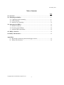
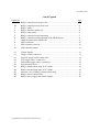
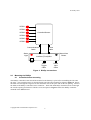
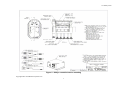
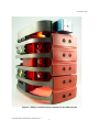
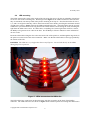
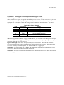
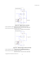
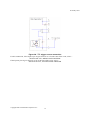
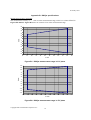
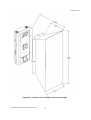
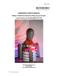
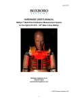
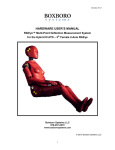
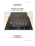
15 January 2010
USER’S MANUAL
RibEye™ Multi-Point Deflection Measurement System
3-Axis Version for the SIDIIs ATD
Hardware Manual for Model 7715
15 January 2010
Boxboro Systems, LLC
978-257-2219
www.boxborosystems.com
Copyright 2007-2010 Boxboro Systems LLC
1
15 January 2010
Table of Contents
Page
1.0 Overview ....................................................................................................................4
2.0 Mounting the RibEye ...............................................................................................6
2.1 Controller/sensor mounting .................................................................................6
2.2 LED mounting .....................................................................................................9
2.3 Interface box mounting.......................................................................................11
3.0 Operating the RibEye..............................................................................................11
3.1 RibEye IP address...............................................................................................12
3.2 Powering up the RibEye .....................................................................................12
3.3 Ambient light cancellation .................................................................................12
4.0 RibEye Software………………………………………………………………….. 12
5.0 RibEye Maintenance ...............................................................................................12
Appendixes
A. DAS/trigger connector pinouts and trigger circuits............................................13
B. RibEye specifications .........................................................................................18
Copyright 2007-2010 Boxboro Systems LLC
2
15 January 2010
List of Figures
Page
Figure No.
1A
1B
2
3
4
5
6
7
8
9
10
RibEye controller/sensor rear view ................................................................4
RibEye controller/sensor front view ...............................................................4
RibEye LEDs ..................................................................................................5
RibEye interface (trunk) box ..........................................................................5
RibEye connections ........................................................................................6
RibEye controller/sensor mounting ................................................................7
RibEye controller/sensor mounted in the SIDIIs thorax.................................8
LEDs mounted on the SIDIIs ribs ..................................................................9
LED connectors .............................................................................................10
LED connector removal.................................................................................10
LED radiation pattern ....................................................................................11
A1
A2
A3
A4
A5
A6
B1
B2
B3
B4
B5
Control signals ...............................................................................................13
Trigger switch connection .............................................................................14
Alternate trigger switch connection...............................................................14
TTL trigger source connection ......................................................................15
Differential trigger source connection ...........................................................16
Armed output circuit………………………………………………………...17
RibEye measurement range in X-Y plane…………………………………..18
RibEye measurement range in Z-Y plane......................................................18
Isometric view of RibEye measurement range ..............................................19
RibEye power requirements ..........................................................................20
RibEye active trigger and control signals......................................................20
Copyright 2007-2010 Boxboro Systems LLC
3
15 January 2010
USER’S MANUAL
RibEye™ Multi-Point Deflection Measurement System
3-Axis Version for the SIDIIs ATD
1.0
Overview
The RibEye measurement system as designed for the SIDIIs anthropomorphic test dummy (ATD) has the
following components:
• The RibEye controller/sensor (Figures 1A and 1B), located in the ATD spine.
• Six light-emitting diodes (LEDs), mounted on the ribs. The LEDs (Figure 2) are designed to be
mounted in the order shown in the photo; that is, the top LED goes on the top rib, etc.
DANGER: The LEDs are very bright when driven at full power. DO NOT LOOK DIRECTLY
AT THE LEDs.
• Interface box (Figure 3), also called the trunk box because it is usually placed in the trunk of the
vehicle.
Figure 1B. RibEye controller/sensor
front view
Figure 1A. RibEye controller/sensor
rear view
Copyright 2007-2010 Boxboro Systems LLC
4
15 January 2010
Figure 3. RibEye interface (trunk) box
Figure 2. RibEye LEDs
The RibEye components are interconnected as shown in Figure 4. Power and communications cables are
provided for connecting the controller/sensor to the interface box in the trunk. The interface box has
sockets for Ethernet connection, power input, and data acquisition system (DAS) connection/trigger input.
Mating connectors and pigtail cables are provided for the power input and DAS/trigger connectors. The
power input cable should be connected to a good quality DC power source. The DAS/trigger cable is
used to provide a trigger input to the RibEye and has several control signals that can be used to interface
the RibEye data acquisition systems (DAS) for automatic control of the RibEye through the DAS.
Copyright 2007-2010 Boxboro Systems LLC
5
15 January 2010
LED#1
LED#2
LED#3
Controller/Sensor
LED#4
LED#5
LED#6
Communications
Cable
Status
Light
Power
Cable
Manual Arm
Button
Interface (Trunk) Box
Ethernet
Jack
DAS/
Trigger
Cable
Power
Input
Cable
Figure 4. RibEye connections
2.0
Mounting the RibEye
2.1
Controller/sensor mounting
The RibEye controller/sensor should be mounted to the dummy’s spine before assembling the ribs onto
the spine. The controller/sensor is mounted using four bolts and a standoff as shown in Figure 5. Route
the LED wires through the large hole on the non-struck side of the spine and out the rib opening. Connect
the LEDs to the RibEye controller/sensor connector. Then slide the RibEye controller/sensor in through
the rib side opening and mount it with the screws and spacers. Figure 6 shows the RibEye controller
mounted in the SIDIIs thorax.
Copyright 2007-2010 Boxboro Systems LLC
6
15 January 2010
Figure 5. RibEye controller/sensor mounting
Copyright 2007-2010 Boxboro Systems LLC
7
15 January 2010
Figure 6. RibEye controller/sensor mounted in the SIDIIs thorax
Copyright 2007-2010 Boxboro Systems LLC
8
15 January 2010
2.2
LED mounting
The LEDs mount to the center of the inside of the ribs using four screws for the top (shoulder) rib and two
screws for each of the remaining ribs. Referring back to Figure 2, the LEDs are shown in the order that
they are mounted, with the top LED in the picture attaching to the top rib. Note that the LEDs for ribs 1,
2, 5, and 6 are angled so that they will be aimed toward the sensor heads, providing the maximum amount
of light to the sensors. Figure 7 shows the LEDs mounted on the ribs. The LED cables must be securely
tied down to prevent them from moving between the LEDs and the sensors during the crash, blocking the
light from the LED to the sensor. If a LED cable, or anything else, blocks light from a LED to a sensor,
the RibEye will generate error codes in the data. See the RibEye software manual for more information
on error codes.
Route the LED cables along the ribs to the non-struck side of the spine box, and through the large holes in
the spine box to the back of the sensor/controller. Make sure that the LED cables will not get pinched by
the motion of the ribs.
DANGER: The LEDs are very bright when driven at full power. Do not look directly at the LEDs
during full power operation.
Figure 7. LEDs mounted on the SIDIIs ribs
The LED cables have connectors on them that mate with the receptacle on the back of the RibEye
controller. The LED connectors are shown in Figure 8. The LED receptacle has locking tabs that must be
Copyright 2007-2010 Boxboro Systems LLC
9
15 January 2010
pressed in with a pen or small tool to disengage the connector from the receptacle, as shown in Figure 9..
(Figure 9 shows a similar connector used on a RibEye for the Hybrid III 50th Male ATD.)
Figure 8. LED connectors
Figure 9. LED connector removal (shown on a Hybrid III 50th male ATD)
Copyright 2007-2010 Boxboro Systems LLC
10
15 January 2010
Figure 10 shows the radiation pattern of the LEDs. Note that the brightest light is directly in front of the
LED (on axis), and the brightness gets lower at larger angles. The RibEye controller continuously adjusts
how hard it drives the LEDs to get a good signal from the sensors.
Figure 10. LED radiation pattern
2.3
Interface box mounting
The interface box, or trunk box, is intended to be mounted in the trunk of the vehicle, near the DAS and
the power source. Four holes are provided on the base of the box for mounting. The interface box can be
mounted in any orientation, but we recommend that it be mounted such that the side of the box with all of
the connectors is easily accessible.
The communications and power cables from the spine box are connected to jacks on the interface box.
An Ethernet cable is used to connect the interface box to a router/hub or directly to a laptop PC. Jacks are
provided for incoming power and DAS/trigger connections.
3.0
Operating the RibEye
The RibEye operates as a stand-alone smart sensor that collects and stores data. In this stand-alone mode,
a PC program is used to control the RibEye and download data. In addition to controlling the RibEye
with the PC program, the interface box has a status light and a manual “Arm” button. The status light
will blink at different rates depending on the state of the RibEye:
• 0.5 Hz = idle with data in memory
• 1.0 Hz = idle with memory erased
• 2.0 Hz = acquiring data
• 5.0 Hz = storing data in flash memory
• 10 Hz = erasing flash memory or downloading data.
Copyright 2007-2010 Boxboro Systems LLC
11
15 January 2010
The Arm button can be used to manually arm the RibEye when it is idle and the memory is erased. You
must hold the Arm button for at least 3 seconds to arm the RibEye.
3.1
RibEye IP address
The RibEye ships from the factory with its IP address set to 192.168.0.240. This IP address can be
changed to work with your local area network (LAN). You can also communicate with the RibEye
directly using a PC, without connecting to a LAN. To directly connect a PC to the RibEye, your PC must
be set up with a fixed IP address on the same subnet as the RibEye. Refer to the RibEye Software Manual
for instructions on how to change the RibEye IP address.
3.2
Powering up the RibEye
When the RibEye is powered up, it will flash each of the LEDs for about 1 second, starting with rib 1 the top (shoulder) rib - and going sequentially through rib 6 (abdominal 2). It takes the RibEye
communications processor about 10 seconds to be ready for communications after it is booted.
3.3
Ambient light cancellation
To compensate for ambient light conditions, the RibEye takes an additional sensor reading each collection
cycle with none of the LEDs turned on. If there is very bright ambient light (much greater than normal
room lighting), the difference between the reading with the LED being turned on and the ambient reading
may not be enough for an accurate position calculation, and the data will display error code values. The
RibEye PC software allows you to view plots of the ambient light data collected.
4.0
RibEye Software
Instructions for installing and operating the RibEye PC software can be found in the RibEye Software
User’s Manual. The software manual can be found on the disk shipped with the RibEye or on the
Boxboro Systems website at http://www.boxborosystems.com/servicepage.html. Updates to the RibEye
PC software can be downloaded from the website as they become available.
5.0
RibEye Maintenance
The RibEye lenses must be kept clean for accurate measurements. Dust and smudges from fingers can
affect the accuracy.
To clean the lenses:
1. Blow the lenses off with canned compressed air (not shop air) to remove any grit
2. Wipe the lenses with a clean, lint-free cloth and lens cleaning solution or alcohol
3. Wipe the lenses with a dry, clean, lint-free cloth.
Never remove the lenses from the case or loosen the lens cover screws. If the lens are loosened, the
calibration will be invalid.
There are no user-serviceable parts in the RibEye.
Copyright 2007-2010 Boxboro Systems LLC
12
15 January 2010
Appendix A. DAS/trigger connector pinouts and trigger circuits
The DAS/trigger interface connector on the RibEye’s interface box is a 24-pin connector. A mating
cable, terminated in a pigtail, is supplied with the RibEye. At this time, 7 of the connector’s 24 pins can
be used. Figure A1 lists the pinouts, pigtail color code, and signal function for these 7 pins. The
remaining pins are for future control and communications connections to DAS systems. The unused
signal pins are internally connected to active signals and should not be connected externally.
Figure A1. Control signals
Pin #
10
20
7
6
11
8
1
Color Code
white
tan
blue
green
black/stripe
violet
black
Function
switch trigger in
5V through 1k resistor for pull-up
ground
differential trigger in +
differential trigger in –
+5V (50 milliamp maximum)
armed output
Figures A2 through A5 show how to connect trigger switches, active TTL level trigger sources, and
differential trigger sources. Where a trigger switch is shown, you can use the same configuration for open
collector transistor output trigger sources. If you want to use a photo-interrupter type trigger source, you
can power it from the 5V supply on pin 8.
Figures A2 through A5 also show the input circuitry in the interface box. Note that the differential
receiver connected to pins 6 and 11 is enabled when a differential trigger is selected. The output of the
receiver is internally connected to pin 10, the “SWITCH OR TTL” trigger input.
WARNING: DO NOT DRIVE PIN 10 WHEN DIFFERENTIAL TRIGGERING IS SELECTED. THIS
MAY CAUSE THE INPUT CIRCUITS TO BE DAMAGED.
WARNING: DO NOT EXCEED THE MAXIMUM INPUT RATING GIVEN IN THE SPECIFICATIONS
SECTION (Appendix B).
Copyright 2007-2010 Boxboro Systems LLC
13
15 January 2010
Figure A2. Trigger switch connection
For this connection, if the switch closes at the start of the event, select—
SWITCH OR TTL, FALLING EDGE TRIGGER
If the switch opens at the start of the event, select—
SWITCH OR TTL, RISING EDGE TRIGGER
Figure A3. Alternate trigger switch connection
For this connection, if the switch closes at the start of the event, select—
SWITCH OR TTL, RISING EDGE TRIGGER
If the switch opens at the start of the event, select—
SWITCH OR TTL, FALLING EDGE TRIGGER
Copyright 2007-2010 Boxboro Systems LLC
14
15 January 2010
Figure A4. TTL trigger source connection
For this connection, if the input at pin 10 goes from 0V to 5V at the start of the event, select—
SWITCH OR TTL, RISING EDGE TRIGGER
If the input at pin 10 goes from 5V to 0V at the start of the event, select—
SWITCH OR TTL, FALLING EDGE TRIGGER
Copyright 2007-2010 Boxboro Systems LLC
15
15 January 2010
Figure A5. Differential trigger source connection
In this configuration, if the differential driver transitions from HIGH (pin 6 voltage > pin 11 voltage) to
LOW (pin 6 voltage < pin 11 voltage) at the start of the event, select—
DIFFERENTIAL, FALLING EDGE TRIGGER
If the differential driver transitions from LOW (pin 6 voltage < pin 11 voltage) to HIGH (pin 6 voltage >
pin 11 voltage) at the start of the event, select—
DIFFERENTIAL, RISING EDGE TRIGGER
Note that when differential triggering is selected, the output of the differential receiver can be monitored
at pin 10.
Copyright 2007-2010 Boxboro Systems LLC
16
15 January 2010
Trunk Box
5v
10k
1 - BLACK
1k
Armed Output
Figure A6. Armed output circuit
Copyright 2007-2010 Boxboro Systems LLC
17
15 January 2010
Appendix B. RibEye specifications
Measurement accuracy and range
The measurement accuracy is +/– 1 mm over the measurement range, which is a volume defined in
Figures B1 and B2. Figure B3 shows an isometric view of the measurement range.
60
50
40
30
X mm
20
10
0
-10
-20
-30
-40
-50
-60
80
90
100
110
120
130
140
150
160
170
180
190
180
190
Y mm
Figure B1. RibEye measurement range in X-Y plane
150
125
100
75
50
Z mm
25
0
-25
-50
-75
-100
-125
-150
80
90
100
110
120
130
140
150
160
170
Y mm
Figure B2. RibEye measurement range in Z-Y plane
Copyright 2007-2010 Boxboro Systems LLC
18
15 January 2010
Figure B3. Isometric view of RibEye measurement range
Copyright 2007-2010 Boxboro Systems LLC
19
15 January 2010
Power requirements
The RibEye can be powered by a good quality DC voltage source from 12 to 36 Volts. Note that the
input power cable is terminated at the user end in pigtails. The red wire is connected to the DC power
supply positive power connection. The black wire is for the DC power supply negative (ground)
connection. The power cable shield should be tied to either the vehicle common ground point or the DC
power supply negative (ground) connection, or both, depending on the configuration of your DC power
grounding scheme. We recommend that you try the various shield connection options and see which
option provides the lowest noise on the RibEye data.
The trunk box has an internal self-resetting polymer fuse. It can take up to ½ hour to reset after an
overload.
The power draw depends on the RibEye’s operating conditions, as shown in Figure B4.
Figure B4. RibEye power requirements
Operating
Conditions
On/idling
Collecting data (typical)
Maximum*
•
Interface Box
3.3
3.3
3.3
Controller + LEDs
Watts
2
5
9
Total
5.3
8.3
12.3
When all LEDs are out of view of both sensors and driven to full power.
Data acquisition and storage
Sample rate: 10,000 samples per second per LED
Acquisition time: 30,000 ms (30 seconds) in D-RAM, 2 seconds in flash
Data is collected to RAM memory and stored post-test in flash memory.
Control signals
The DAS/trigger interface cable has 20 conductors used for trigger inputs and control/hand-shaking
signals to an external data acquisition system. At this time, only the trigger and armed output signals are
programmed. The other control wires are not used, but are connected to internal circuitry and should not
be connected. All unused control wires should be individually insulated and protected.
The active trigger and control signals are listed in Figure B5.
Figure B5. RibEye active trigger and control signals
Pin #
10
20
7
6
11
8
1
Color Code
white
tan
blue
green
black/stripe
violet
black
Function
switch trigger in
5V through 1k resistor for pull-up
ground
differential trigger in +
differential trigger in –
+5V (50 milliamp maximum)
armed output
Copyright 2007-2010 Boxboro Systems LLC
20
15 January 2010
Differential trigger inputs (pins 6, 11)
•
Maximum differential input voltage: +/– 12 VDC
•
Minimum differential input voltage: +/– 0.2 VDC
•
Common mode input voltage +/– 12 VDC
Switch trigger input (pin 10 with respect to pin 7, ground)
•
Maximum input voltage = 5.0 VDC
•
Minimum “on” voltage = 3.3 VDC
•
Maximum “off” voltage = 0.4 VDC
•
Current limited by 1k resistor
Additional 5V for external power (pin 8)
•
Output voltage 4.75 to 5.25 volts
•
Limit external loads to 50 milliamp maximum
•
Short circuit will cause resettable fuse to trip
Armed output (pin 1)
•
Output voltage 4.75 to 5.25 volts at 0.5 ma max when armed
•
Output voltage 0.5 volts when disarmed
•
See Appendix A for a schematic of the armed output circuit
Communication and power cables
These cables connect the trunk box in the vehicle trunk to the RibEye’s controller. The communication
and power cables are internal to the RibEye system and should not be modified in any way. No user
connections are available on these cables.
Copyright 2007-2010 Boxboro Systems LLC
21