1
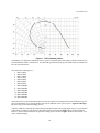
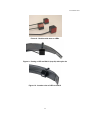
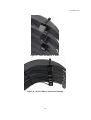
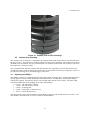
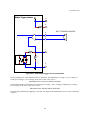
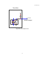
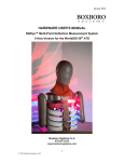
1 November 2010
USER’S MANUAL
RibEye™ Multi-Point Deflection Measurement System
2-Axis Version for 50th Male Hybrid III ATD
Hardware Manual for Model 7800B
1 November 2010
Boxboro Systems, LLC
978-257-2219
www.boxborosystems.com
Copyright 2010 Boxboro Systems LLC
1
1 November 2010
Table of Contents
Page
1.0
Overview
......................................................................................................... 4
2.0
Mounting the RibEye ......................................................................................... 4
2.1 Controller mounting .................................................................................... 4
2.2 Sensor head mounting................................................................................ 9
2.3 LED connector block mounting ................................................................... 9
2.3 LED mounting............................................................................................. 9
2.4 Interface box mounting .............................................................................. 13
3.0
Operating the RibEye........................................................................................ 13
3.1 RibEye IP address ..................................................................................... 14
3.2 LED flashing on power up.......................................................................... 14
4.0
RibEye Software................................................................................................ 14
5.0
RibEye Maintenance ......................................................................................... 14
Appendixes
A. RibEye specifications.................................................................................. 15
B. Trigger Inputs and Armed Output circuits .................................................... 18
Copyright 2010 Boxboro Systems LLC
2
1 November 2010
List of Figures and Tables
Figure No.
Page
1
RibEye components..................................................................................... 5
2
RibEye components mounted on spine box – side view............................... 6
3
RibEye controller mounted on spine box – rear view.................................... 6
4
RibEye connections ..................................................................................... 7
5
Diagrams for mounting RibEye components ................................................ 8
6
LED cases with angled backs (36 and 22 degrees) and flat back................. 9
7
LED radiation pattern .................................................................................. 10
8
Double-stick tape on LEDs.......................................................................... 11
9
Putting a LED on Rib #1 (top rib) with nylon tie ........................................... 11
10
Another view of LED on Rib #1 ................................................................... 11
11
LEDs on Ribs #1, 2, and 3 .......................................................................... 12
12
All six LEDs on one side of ribcage............................................................. 12
13
Outside view of LED mountings .................................................................. 13
A1
RibEye measurement range in X-Y plane ................................................... 15
B1
Trigger switch connection ........................................................................... 19
B2
Alternate trigger switch connection ............................................................. 20
B3
TTL trigger source connection..................................................................... 21
B4
Differential trigger source connection .......................................................... 22
B5
Armed Output Circuit……………………………………………………………..23
Table No.
A1
A2
A3
B1
RibEye accuracy in Z positions, mm ........................................................... 15
RibEye power requirements........................................................................ 16
RibEye trigger and control signals............................................................... 16
Trigger signals ............................................................................................ 18
Copyright 2010 Boxboro Systems LLC
3
1 November 2010
USER’S MANUAL
RibEye™ Multi-Point Deflection Measurement System
2-Axis Version for 50th Male Hybrid III ATD
Hardware Manual for Model 7800B
1.0
Overview
The RibEye measurement system as designed for this anthropomorphic test dummy (ATD) has
the following components:
• The RibEye controller, also called the spine box (“A”), located in the ATD spine.
• Two optical sensor heads (“B”) that will attach to sensor head mounting flanges (“C”).
• Twelve light-emitting diodes (LEDs), two sets of 6 each (“D”), mounted on the ribs or
sternum. Some of the LEDs have an angled mounting surface that aims the LED toward
the sensor head to minimize power requirements.
DANGER: The LEDs are very bright when driven at full power. Do not look directly at
the LEDs.
• Two LED connector blocks (“E”) that will be mounted on the sides of the spine box.
• The interface box (“F”), also called the trunk box because it is typically placed in the
trunk of the vehicle.
The RibEye specifications appear in Appendix A. Figures 1, 2, and 3 identify each of the
RibEye components. Figure 4 shows how the components are interconnected. The sensor heads
and LED connector blocks are permanently connected to the controller (spine box). Power and
communications cables are provided for connecting the controller to the interface box (trunk
box). The interface box has sockets for Ethernet connection, power input, and data acquisition
system (DAS) connection/trigger input. Mating connectors and pigtail cables are provided for the
power input and DAS/trigger connectors. The power cable should be connected to a DC power
source. The DAS/trigger cable is used to provide a trigger input to the RibEye. Appendix B
contains the DAS/trigger connector pinouts and trigger circuits.
2.0
Mounting the RibEye
Diagrams for mounting the RibEye controller, sensor heads, and LED connector blocks are
shown in Figure 5. The controller, sensor heads, and connector blocks should be mounted to the
dummy’s spine prior to assembling the ribs onto the spine. The following mounting instructions
are for application in the 50th Male Hybrid III ATD, Model 7800B.
2.1
Controller mounting
The RibEye controller is mounted inside the top of the dummy spine in the rectangular opening.
The power and communication cables should be connected to the controller before the controller
is mounted in the spine. The controller slides into the spine and is attached with four screws
(Figure 3 A). The power and communication cables will come out of the back of the spine and
then down under the skin to exit at the bottom of the jacket. These cables will be routed to the
interface box.
Copyright 2010 Boxboro Systems LLC
4
1 November 2010
F
E
E
A
C
D
B
B
D
Figure 1. RibEye components
.
Copyright 2010 Boxboro Systems LLC
5
1 November 2010
A
E
Figure 2. RibEye components mounted on spine box – side view
A
Figure 3. RibEye controller mounted on spine box – rear view
Copyright 2010 Boxboro Systems LLC
6
1 November 2010
Left
Sensor
Right
Sensor
LED#1
LED#7
LED#2
LED#8
LED#3
LED#9
Controller
(Spine Box)
LED#4
LED#10
LED#5
LED#11
LED#6
LED#12
Communications
Cable
Status
Light
Power
Cable
Manual Arm
Button
Interface (Trunk Box)
Ethernet
Jack
DAS/
Trigger
Cable
Power
Input
Cable
Figure 4. RibEye connections
Copyright 2010 Boxboro Systems LLC
7
1 November 2010
Figure 5. Diagrams for mounting RibEye components
8
1 November 2010
2.2
Sensor head mounting
The two optical sensor heads are mounted to the sides of the spine on flanges. Each mounting flange is
attached to the spine with four screws. Note that the mounting flanges have alignment pins that fit into
precision holes in the spine. Each of the two sensor assemblies is attached to its mounting flange with
two screws. Note that the sensor assemblies are oriented such that the cable is pointed upwards. The
sensor heads and flanges are also shown in Figure 1 B and C and Figure 5.
2.3
LED connector block mounting
The two LED connector blocks mount on the sides of the spine box with two captive screws for each.
Figure 2 E shows the connector block on the left side of the spine. Note that the connectors have a
locking tab that must be pressed to remove the LED connector from the connector block.
2.4
LED mounting
After the controller, sensor heads, and connector block are mounted, the ribs can be assembled onto the
spine. Next, the LEDs can be mounted to the ribs. For best performance, the LEDs should be mounted
+/–70 mm in the dummy Y direction from the centerline of the sternum, or approximately 90 mm along
the curve of the ribs from the centrline of the sternum. These are the LED positions shown in Figure 5.
This places the LEDs on the ribs where the damping material begins to taper down from full thickness.
Figures 9 through 12 show the LEDs mounted in the proper positions.
The top rib is Rib 1, and the bottom rib is Rib 6. Left and right refer to the dummy’s left and right sides.
The LED cables are marked with the default location where the LEDs are intended to be mounted. The
LED cases have three different styles (Figure 6):
• 36-degree angled back, intended for mounting on Ribs 1 and 6
• 22-degree angled back, intended for mounting on Ribs 2 and 5
• Flat back, intended for mounting on Ribs 3 and 4, the center ribs.
Figure 6. LED cases with angled backs (36 and 22 degrees) and flat back
The LEDs are angled so that they will be aimed toward the sensor heads, providing the maximum amount
of light to the sensors. Figure 7 shows the radiation pattern of the LEDs. Note that the brightest light is
directly in front of the LED (on axis), and the brightness gets lower at larger angles. The RibEye
controller continuously adjusts how hard it drives the LEDs to get a good signal from the sensors.
9
1 November 2010
Figure 7. LED radiation pattern
The RibEye uses different calibration curves to process the LED data, depending on which rib (the Z-axis
location) that the LED is mounted on. To obtain the guaranteed accuracy, the LEDs must be mounted on
the ribs specified below.
The LED cable markings are—
1. RIB 1 LEFT
2. RIB 2 LEFT
3. RIB 3 LEFT
4. RIB 4 LEFT
5. RIB 5 LEFT
6. RIB 6 LEFT
7. RIB 1 RIGHT
8. RIB 2 RIGHT
9. RIB 3 RIGHT
10. RIB 4 RIGHT
11. RIB 5 RIGHT
12. RIB 6 RIGHT
The LED cases have holes drilled in them to allow the LEDs to be mounted to the ribs with nylon zip ties.
We recommend the use of strong double-stick tape in addition to the nylon zip ties. Figures 8 through
11 show steps in the LED mounting process.
After the LEDs are mounted, the LED cables should be tied down, also using nylon zip ties, to prevent the
cables from crossing the path between the LEDs and the sensor heads (Figure 12). If the light from a
LED to a sensor head is blocked, the position reading will be invalid. Figure 13 shows the outside view
of the LED mountings.
10
1 November 2010
Figure 8. Double-stick tape on LEDs
Figure 9. Putting a LED on Rib #1 (top rib) with nylon tie
Figure 10. Another view of LED on Rib #1
11
1 November 2010
Figure 11. LEDs on Ribs #1, 2, and 3
Figure 12. All six LEDs on one side of ribcage
12
1 November 2010
Figure 13. Outside view of LED mountings
2.5
Interface box mounting
The interface box, or trunk box, is intended to be mounted in the trunk of the vehicle, near the DAS and
the power source. Four holes are provided on the base of the box for mounting. The interface box can be
mounted in any orientation, but we recommend that it be mounted such that the side of the box with all of
the connectors is easily accessible.
The communications and power cables from the spine box are connected to jacks on the interface box.
An Ethernet cable is used to connect the interface box to a router/hub or directly to a laptop PC. Jacks are
provided for incoming power and DAS/trigger connections.
3.0
Operating the RibEye
The RibEye operates as a stand-alone smart sensor that collects and stores data. In this stand-alone mode,
a PC program is used to control the RibEye and download data. In addition to controlling the RibEye
with the PC program, the interface box has a status light and a manual “Arm” button. The status light
will blink at different rates depending on the state of the RibEye:
• 0.5 Hz = idle with data in memory
• 1.0 Hz = idle with memory erased
• 2.0 Hz = acquiring data
• 5.0 Hz = storing data in flash memory
• 10 Hz = erasing flash memory.
The Arm button can be used to manually arm the RibEye when it is idle and the memory is erased. You
must hold the Arm button for at least 3 seconds to arm the RibEye.
13
1 November 2010
3.1
RibEye IP address
The RibEye ships from the factory with its IP address set to 192.168.0.240. This IP address can be
changed to work with your local area network (LAN). You can also communicate with the RibEye
directly using a PC, without connecting to a LAN. To directly connect a PC to the RibEye, your PC must
be set up with a fixed IP address on the same subnet as the RibEye. Refer to the RibEye Software Manual
for instructions on how to change the RibEye IP address.
3.2
LED flashing on power up
When the RibEye is powered on, it will flash each of the LEDs for about 1 second. The LEDs will flash
in the following order:
1.
2.
3.
4.
5.
6.
7.
8.
9.
10.
11.
12.
4.0
Rib 1 Left
Rib 2 Left
Rib 3 Left
Rib 4 Left
Rib 5 Left
Rib 6 Left
Rib 1 Right
Rib 2 Right
Rib 3 Right
Rib 4 Right
Rib 5 Right
Rib 6 Right
RibEye Software
Instructions for installing and operating the RibEye PC software can be found in the RibEye Software
User’s Manual. The software manual can be found on the disk shipped with the RibEye or on the
Boxboro Systems website at http://www.boxborosystems.com/servicepage.html. Updates to the RibEye
PC software can be downloaded from the website as they become available.
5.0
RibEye Maintenance
The RibEye lenses must be kept clean for accurate measurements. Dust and smudges from fingers can
affect the accuracy.
To clean the lenses:
1. Blow the lenses off with canned compressed air (not shop air) to remove any grit
2. Wipe the lenses with a clean, lint-free cloth and lens cleaning solution or alcohol
3. wipe the lenses with a dry, clean, lint-free cloth.
Never remove the lenses from the case or loosen the lens cover screws. If the lens are loosened, the
calibration will be invalid.
There are no user-serviceable parts in the RibEye.
14
1 November 2010
Appendix A. RibEye specifications
Measurement accuracy and range
The measurement range of the RibEye in the X-Y plane is shown in Figure A1.
X Position (mm)
Hybrid III RibEye X-Y Range
140
130
120
110
100
90
80
70
60
50
40
30
20
10
0
-120
-100
-80
-60
-40
-20
0
20
40
60
80
100
120
Y Position (mm)
Figure A1. RibEye measurement range in X-Y plane
The accuracy of the RibEye depends on the Z (up and down) position of the ribs as shown in Table A1.
Refer to the calibration report for the RibEye to see the measured accuracy over the measurement range.
Table A1. RibEye accuracy in Z positions, mm
Z deflection (per rib)
0 (no Z deflection)
up to +/–5
-5 to -10; 5 to 10
X Accuracy
1
1
2
Y Accuracy
1
2
2
Power requirements
The RibEye can be powered by any DC voltage source from 12 to 36 Volts. The power cable from the
RibEye’s interface box to the power source has two conductors: the red wire is positive, and the black
wire is negative. The interface box has an internal self-resetting polymer fuse. It can take up to ½ hour to
reset after an overload.
15
1 November 2010
The power draw depends on the RibEye’s operating conditions, as shown in Table A2.
Table A2. RibEye power requirements
Operating
Conditions
On/idling
Collecting data (typical)
Maximum*
Interface Box
3.3
3.3
3.3
Controller + LEDs
Watts
2
5
9
Total
5.3
8.3
12.3
* When all LEDs are out of view of both sensors and driven to full power.
Data acquisition and storage
Sample rate: 10,000 samples per second per LED
Acquisition time: 30,000 ms (30 seconds) in D-RAM, 2 Seconds in Flash
Data is collected to RAM memory and stored post-test in flash memory.
Control signals
The DAS/trigger interface cable has 8 conductors used for trigger inputs and control/hand-shaking signals
to an external data acquisition system.The trigger and control signals are listed in Table A3. All unused
control wires should be individually insulated and protected. The Trigger output signal is not used on this
model.
Table A3. RibEye trigger and control signals
Pin #
1
2
3
4
5
6
7
8
Color Code
white
brown
blue
green
orange
yellowt
black
red
Function
switch trigger in
5V through 1k resistor for pull-up
ground
differential trigger in +
differential trigger in –
+5V (50 milli-amp maximum)
armed output
trigger output
Differential trigger inputs (pins 4, 5)
•
Maximum differential input voltage: +/– 12 VDC
•
Minimum differential input voltage: +/– 0.2 VDC
•
Common mode input voltage +/– 12 VDC
Switch trigger input (pin 1 with respect to pin 3, ground)
•
Maximum input voltage = 5.0 VDC
•
Minimum “on” voltage = 3.3 VDC
•
Maximum “off” voltage = 0.4 VDC
•
Current limited by 1k resistor
16
1 November 2010
Additional 5V for external power (pin 6)
•
Output voltage 4.75 to 5.25 volts
•
Limit external loads to 50 milli-amp maximum
•
Short circuit will cause resettable fuse to trip
Armed output (pin 7)
•
Output voltage 4.75 to 5.25 volts at 0.5 ma max when armed
•
Output voltage 0.5 volts when disarmed
•
See Appendix B for a schematic of the armed output circuit
Communication and power cables
These cables connect the interface box in the vehicle trunk to the RibEye’s controller. The
communication and power cables are internal to the RibEye system and should not be modified in any
way. No user connections are available on these cables.
Note that the input power cable is terminated at the user end in pigtails. The red wire is connected to the
DC power supply positive power connection. The black wire is for the DC power supply negative
(ground) connection. The power cable shield should be tied to either the vehicle common ground point or
the DC power supply negative (ground) connection, or both, depending on the configuration of your DC
power grounding scheme. We recommend that you try the various shield connection options and see
which option provides the lowest noise on the RibEye data.
17
1 November 2010
Appendix B. Trigger Inputs and Armed Output circuits
The DAS/trigger interface connector on the RibEye’s interface box is an 8-pin Lemo connector. A
mating cable, terminated in a pigtail, is supplied with the RibEye. At this time, 7 of the connector’s 8
pins can be used for triggering and status. The trigger output is not programmed on this model. Table
B1 lists the pinouts, pigtail color code, and signal function . Refer to the specifications sections for
maximum voltages applied to these connections
Table B1. Trigger signals
Pin #
1
2
3
4
5
6
7
8
Color Code
white
brown
blue
green
orange
yellowt
black
red
Function
switch trigger in
5V through 1k resistor for pull-up
ground
differential trigger in +
differential trigger in –
+5V (50 milli-amp maximum)
armed output
trigger output
Figures B1–B4 show how to connect trigger switches, active TTL level trigger sources, and differential
trigger sources. Where a trigger switch is shown, you can use the same configuration for open collector
transistor output trigger sources. If you want to use a photo-interrupter type trigger source, you can
power it from the 5V supply on pin 8.
Figures B1–B4 also show the input circuitry in the interface box. Note that the differential receiver
connected to pins 6 and 11 is enabled when a differential trigger is selected. The output of the receiver is
internally connected to pin 10, the “SWITCH OR TTL” trigger input.
WARNING: DO NOT EXCEED THE MAXIMUM INPUT RATING GIVEN IN THE SPECIFICATIONS
SECTION (Appendix A).
Figure B5 shows the armed output circuitry that you can use to monitor the state of the RibEye.
18
1 November 2010
5V
RibEye Trigger Interface
6
1k
2
4
5
1
1k
10k
Trigger Switch
3
Figure B1. Trigger switch connection
For this connection, if the switch closes at the start of the event, select—
SWITCH OR TTL, FALLING EDGE TRIGGER
If the switch opens at the start of the event, select—
SWITCH OR TTL, RISING EDGE TRIGGER
19
1 November 2010
5V
RibEye Trigger Interface
6
1k
2
4
5
Trigger Switch
1
1k
10k
3
Figure B2. Alternate trigger switch connection
For this connection, if the switch closes at the start of the event, select—
SWITCH OR TTL, RISING EDGE TRIGGER
If the switch opens at the start of the event, select—
SWITCH OR TTL, FALLING EDGE TRIGGER
20
1 November 2010
5V
RibEye Trigger Interface
6
1k
2
4
5
TTL TRIGGER SOURCE
1
1k
2
10k
3
Figure B3. TTL trigger source connection
For this connection, if the input at pin 1 goes from 0V to 5V at the start of the event, select—
SWITCH OR TTL, RISING EDGE TRIGGER
If the input at pin 1 goes from 5V to 0V at the start of the event, select—
SWITCH OR TTL, FALLING EDGE TRIGGER
21
1
1 November 2010
5V
RibEye Trigger Interface
6
1k
2
DIFF TRIGGER SOURCE
4
5
1
1k
10k
3
Figure B4. Differential trigger source connection
In this configuration, if the differential driver transitions from HIGH (pin 4 voltage > pin 5 voltage) to
LOW (pin 4 voltage < pin 5 voltage) at the start of the event, select—
DIFFERENTIAL, FALLING EDGE TRIGGER
If the differential driver transitions from LOW (pin 4 voltage < pin 5 voltage) to HIGH (pin 4 voltage >
pin 5 voltage) at the start of the event, select—
DIFFERENTIAL, RISING EDGE TRIGGER
Note that when differential triggering is selected, the output of the differential receiver can be monitored
at pin 10.
22
1 November 2010
Trunk Box
5v
10k
7 - BLACK
1k
Armed Output
Figure B5. Armed output circuit
23