1
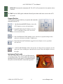
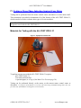
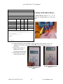
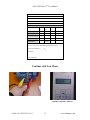
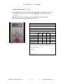
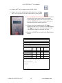
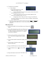
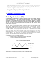
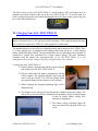
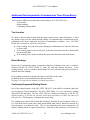
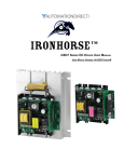
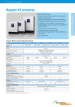
ALL-TEST Pro, LLC
ALL-TEST PRO® 31 User Manual
Table of Contents
I. Introduction......................................................................................................................... 4
II. Safety ................................................................................................................................. 5
Instrument Warnings and Considerations .......................................................................... 5
General Safety Considerations ........................................................................................... 5
III. ALL-TEST PRO 31 Kit Components ..............................................................................6
Instrument Operation..........................................................................................................6
Input Section .................................................................................................................. 6
Display Section .............................................................................................................. 7
Indicator Light Section...................................................................................................7
Display Screen ...............................................................................................................7
Keypad Section ..............................................................................................................8
Instrument Test Leads ....................................................................................................8
IV. Testing a Three Phase Induction Squirrel Cage Motor.................................................... 9
Materials for Testing with the ALL-TEST PRO 31...........................................................9
Winding Test ................................................................................................................10
ERROR CODES .............................................................................................................. 11
Phase Balance Test.......................................................................................................15
Insulation Resistance Testing.......................................................................................17
Rotor Test.....................................................................................................................19
Bar Test ........................................................................................................................19
Wave Form Test ...........................................................................................................20
Changing the Motor Test Frequency................................................................................21
V. Additional Functions and Features.................................................................................. 22
Electro-Magnetic Interference (EMI): ............................................................................. 22
Resetting the Unit.............................................................................................................23
VI. Charging Your ALL-TEST PRO 31 .............................................................................. 24
VII. Data Interpretation Three Phase Motors.......................................................................25
Data Interpretation Tables:...............................................................................................25
Additional Data Interpretation Considerations Three Phase Motors ............................... 26
Test Location................................................................................................................ 26
Rotor Windings ............................................................................................................ 26
Confirming Suspected Winding Shorts........................................................................26
Method 1: Rotor Compensation. ..................................................................................27
Method 2: Variable Frequency Test.............................................................................27
VIII. DC Motor Testing .......................................................................................................29
©2006, ALL-TEST Pro
www.alltestpro.com
Testing an Assembled DC Motor.................................................................................29
Series DC motor:..........................................................................................................29
See Data Interpretation................................................................................................. 29
Compound or shunt DC motor:....................................................................................29
Armature Testing..........................................................................................................30
DC Motor Analysis ..........................................................................................................30
IX. Additional Test Methods................................................................................................ 31
Wound Rotor Motors .......................................................................................................31
Wye-Delta Motors............................................................................................................31
Capacitor Testing .............................................................................................................32
X. Tech Support and Information ........................................................................................ 33
XI. Available Accessories for the ALL-TEST PRO 31 .......................................................33
XII. Training Class...............................................................................................................33
PATENT PENDING 0401128-4
ALL-TEST PRO 31® User Manual
I. Introduction
The light-weight, hand-held instrument can be used for immediate detection of winding
shorts, insulation to ground faults, cable faults and more on AC/DC electric motors,
transformers, coils, machine tool equipment, linear motors and much more. Testing can be
performed at the motor connection box or from the disconnect or motor control center
hundreds of feet away.
The ALL-TEST PRO® 31 (AT31) is designed to provide simple test method:
for troubleshooting faults
commissioning new and rebuilt machines
quality assurance in electric motors and other wound equipment.
The patented tests performed for early winding fault detection:
winding impedance test
phase angle
I/F current frequency response tests.
EMI (Electro-Magnetic Interference) test for detection of low-level EMI
currents that can affect readings and may be the result of other faults within the
motor circuit
Note: The ALL-TEST PRO® 31 provides real time measurements of the on-going test.
When combined with the ALL-TEST IV PRO 2000® provides the most comprehensive offline motor analysis system available at any price.
Insulation Resistance to ground: To prevent electrical shocks and to assure safety of personnel
the AT31 provides an insulation to ground test. The insulation resistance test provides either
500 or 1,000 VDC, to measure the insulation resistance up to 500 Meg-Ohm. For winding with
voltages rated up to 6000V.
©2006, ALL-TEST Pro, LLC
4
www.alltestpro.com
ALL-TEST PRO 31® User Manual
II. Safety
CAUTION: The AT31 is designed to test de-energized equipment safely and
quickly. Improper application of the AT31 on live circuits is a danger to the
user and will result in the destruction of the testing circuit, requiring instrument
replacement.
Instrument Warnings and Considerations
The ALL-TEST PRO® 31 is a CE registered instrument.
The following is a list of considerations for equipment life and accurate data collection:
Ensure that all power has been removed from the circuit being tested, including
static power stored in capacitors Discharge all capacitors being tested.
Attaching the AT31 to live voltage will destroy the unit and void the warranty.
Do not attempt to change the batteries. Contact your distributor of the AT31, ALLTEST Pro at 860 395-2988 or via email, [email protected], to have the battery
pack replaced.
Do not open the instrument. Electrostatic charges may damage surface mount
electronics. Please contact your vendor or ALL-TEST Pro authorized repair center.
Use only the supplied charger for charging the instrument. It is an integral part of the
charging circuit. Using the wrong charger will damage your instrument.
General Safety Considerations
Following are general safety considerations for using the AT31 motor tester:
The AT31 is an off-line motor tester. All power and residual power must be
disconnected. It provides a safe method of testing your electric motors.
Follow all safety rules of your company and OSHAct (or country equivalent) for off-line
testing methods, including appropriate Personal Protective Equipment (PPE). Improper or
unsafe operation of the equipment is the sole responsibility of the user.
For MCA testing, the AT31 sends out a low voltage, high frequency signal not harmful to
the technician or most electronic equipment (variable frequency drives and soft starts).
However, electronic equipment and personnel must observe appropriate safety considerations
(disconnect electronic equipment) when performing the insulation to Ground resistance test
(Meg-Ohm) test.
©2006, ALL-TEST Pro, LLC
5
www.alltestpro.com
ALL-TEST PRO 31® User Manual
III. ALL-TEST PRO® 31 Kit Components
Figure 1: AT 31 Kit
The AT31 kit contains all of the necessary components necessary to test most electrical
machinery:
ALL-TEST PRO® 31 instrument
Batteries (installed)
Test leads and clips
Charger (115 or 230 Volt)
Manual on CD Rom
Carrying Pouch
Reset Key (On units before Serial number 2029)
Instrument Operation
The instrument is divided up into three working areas:
1) Input Section
2) Display Area
3) Keypad
Input Section
The input section provides all the external connections to the ALL-TEST PRO® 31
A. Test lead port
B. Charger port
D
C. Ground test lead port for Insulation to Ground
Measurements
D. Reset Button (Serial number 2029 and higher)
B
A
©2006, ALL-TEST Pro, LLC
6
www.alltestpro.com
C
ALL-TEST PRO 31® User Manual
Display Section
The display section is divided into 2 sections:
1) Indicator Lights
2) Display Screen
The Indicator Lights section informs the
operator when an operation or test is being
performed.
E
F
G
The Display screen allows the operator to
select tests to be performed by the AT31.
Indicator Light Section
E. Charging light Indicates that the unit
is charging, light is illuminated red while charging, light is green when fully charged.
F. Test indicator light
testing
Light is illuminated green when the unit is
G. Insulation Test indicator light The light illuminates yellow when the
instrument is testing insulation resistance. Caution Applied voltage is
500 or 1,000 Volts DC.
Display Screen
The display screen on provides the AT 31 with
individual icons to select and perform the various
motor winding tests.
H. Z/ Icon Performs: Impedance (Z), Phase Angle ( ), Current/Frequency (I/F) and
Phase Balance tests (used for winding shorts).
I.
ROT Icon Performs the Rotor test, (used to find squirrel cage induction motor
rotors faults).
J.
INS Icon Performs the Insulation to ground resistance test selection (used to verify
that the insulation to ground resistance is sufficient to prevent electrical shock).
K. Battery charge level indicator, fully charged battery will have 7 bars. (It is
recommended to keep the AT31 on charge when not in use to ensure proper
operation).
©2006, ALL-TEST Pro, LLC
7
www.alltestpro.com
ALL-TEST PRO 31® User Manual
L. PWR OFF Icon turns the instrument off. The AT31 will automatically shut-off after about
5 minutes
M. EMI Tests for EMI signals within the Motor System that could cause errors in the AT31
test results
Keypad Section
The keypad section provides keys to operate and control the
functions of the AT31.
N. Up direction and MODE button, returns the
AT31 display screen to the main menu
O. On and left direction (F1) button, turns the
AT31 on and moves the curser across the
display screen toward the left
P. Zero and Selection ( OK ) button, selects which test to perform and provides
reference selection to calculate % differences
Q. Down direction and Test button, toggles between display screens, performs
selected tests.
R. Left (F2) and Hz button, allows the operator to change the test frequency for the
moves the cursor winding test, and moves the cursor across the display screen to
the right.
Instrument Test Leads
The ALL-TEST PRO 31 uses a 15 pin DB connector
for winding testing. The red test lead is the output and
the black test lead, is the return. For Insulation testing
the yellow test lead should be connected to ground.
©2006, ALL-TEST Pro, LLC
8
www.alltestpro.com
ALL-TEST PRO 31® User Manual
IV. Testing a Three Phase Induction Squirrel Cage Motor
Testing can be performed from the motor control center, disconnect or at the motor itself.
This instruction is provided to demonstrate all of the features of the ALL-TEST PRO® 31,
which can also be used to evaluate other types of electric machines.
Note: The M2000 demo motor is used in this manual for procedural purposes only, it is not
designed to work with the ALL-TEST PRO 31
Materials for Testing with the ALL-TEST PRO® 31
Figure 2: Equipment and Materials
To perform a motor test with the ALL-TEST PRO® 31 requires:
ALL-TEST PRO® 31
Test leads and lead clips
A pen and paper (or a copy of the Motor Test Form on page 28).
Testing can be performed directly at the motor, at the nearest motor control center or
disconnect. For purposes of this manual, we will test at the motor using an M2000 training motor, this is for
procedure only (the M2000 is not designed to work with AT31).
©2006, ALL-TEST Pro, LLC
9
www.alltestpro.com
ALL-TEST PRO 31® User Manual
Operating Procedure 3-Phase Motors
Winding Test
Measures and displays the winding impedance (Z), Phase Angle ( ), Current Frequency
response (I/F) and Impedance phase balance.
1) Label the three motor leads T1, T2,
T3. It is very important to take the
data in the same order for long term
trending.
2) Connect the Test leads to the Motor
leads T1 & T2. Note: For quick
trouble shooting the order of the
readings is not important. However,
for long term trending of the data
should be preformed in the same
order each time. Optional: Connect
the Yellow lead to ground, this is only
required for measuring insulation to
ground.
Turn the instrument On
Depress and hold the F1/ON key for 1 to 3
seconds. This will bring up the main display
screen.
Select the Motor Test
1) Using the F1 and
F2, keys highlight the
winding test Icon
2) Depress the Zero/OK Key to select the Winding test (Z/ ) from the main menu.
Observe/Record the Test Data
1) The default value is 200 Hz, as displayed in the bottom right corner of the display
screen.
a. The value of the impedance should be between 1 and 999 . If the Z is less
than 1 or greater than 999 change the test frequency of the winding test
(see Changing the Motor Test Frequency).
b. The current frequency response value (I/F) must be between -15 and -50, if
it is not change the frequency of the winding test.
c. If the phase angle (Fi) is less than 150, change the winding test frequency.
©2006, ALL-TEST Pro, LLC
10
www.alltestpro.com
ALL-TEST PRO 31® User Manual
Note: If any of the measurements fall outside the above ranges, the test is not valid.
2) Display screen 2 displays the results of the current frequency
test. To view display screen 2 depress the Test key.
Display screen 1: Displays the measured impedance in ohms 107,
phase angle in degrees 660, and the frequency of the winding test,
200 Hz. The screen number (1) is displayed in the upper left hand
corner.
Figure 2 Display Screen 1
Display Screen 2: Displays the results of the Current
Frequency (I/F) response test. (-45), (the current at 400 Hz is
45% lower than the current at 200 Hz) The doubled test
frequency is displayed in the lower right hand corner; screen
number (2) is displayed in the upper right hand corner.
3) To return to the Display Screen 1
depress the test key again which
displays the impedance and phase
angle measurement.
4) Record the measured values on the
motor test form.
ERROR CODES
If the impedance readings are out of range an error code will be displayed on
the measurement screen.
E1 error code means the impedance value is greater than 1000 ohms
E2 error code means the impedance value is greater than 10,000 ohms.
©2006, ALL-TEST Pro, LLC
11
www.alltestpro.com
ALL-TEST PRO 31® User Manual
ALL-TEST Pro® 31 Motor Test Form
Motor ID:
Continue with Other Phases
Location:
Test Date:
5) Move the test leads to T2 T3 to
make the measurements on the next
phase.
Test Frequency
Impedance (Z)
Phase
1-2
107
Phase Angle (°)
66
Z-Test or I/F
-45
Phase
2-3
Phase
1-3
Phase balance (opt)
Ins Resistance
Test
Voltage
Was rotor set to lowest value during phase balance test? Y__ N__
Rotor test performed? Y___ N___
Comments:
© ALL-TEST Pro
6) Read the Impedance (Z) and Phase Angle ( ) values from display screen 1 for
winding 2. Do not fill in the phase balance until all three phases have been
measured.
7) Depress the test key to
display the Current
Frequency Response (I/F).
8) Record these test results
on the motor test form.
Winding 2 Impedance &
Phase 1
©2006, ALL-TEST Pro, LLC
12
Winding 2 Current Frequency
Response 1
www.alltestpro.com
ALL-TEST PRO 31® User Manual
ALL-TEST Pro® 31 Motor Test Form
Motor ID:
Location:
Test Date:
Test Frequency
Phase
1-2
107
Phase
2-3
107
Phase Angle (°)
66
66
Z-Test or I/F
-45
-45
Impedance (Z)
Phase
1-3
Phase balance (opt)
Ins Resistance
Test
Voltage
Was rotor set to lowest value during phase balance test? Y__ N__
Rotor test performed? Y___ N___
Comments:
© ALL-TEST PRO
Continue with Last Phase
Winding 3 Impedance & Phase 1
©2006, ALL-TEST Pro, LLC
13
www.alltestpro.com
ALL-TEST PRO 31® User Manual
9) Move the Test Leads to T1 & T3
10) Read the Impedance (Z) and Phase Angle ( ) values from display screen 1 for
winding 2. Do not fill in the phase balance until all three phases have been
measured.
11) Depress the test key to display the Current Frequency Response (I/F).
12) Record these test results on the motor test form
ALL-TEST Pro 31 Motor Test Form
Motor ID: Test Motor
Location: Warehouse
Test Date: 8/8/06
Test Frequency 200 Hz
Phase
1-2
107
Phase
2-3
107
Phase Angle (°)
66
66
66
Z-Test or I/F
-45
-45
-45
Impedance (Z)
Phase
1-3
109
Phase balance (opt)
Winding 3 Current Frequency
Ins Resistance
Test
Voltage
Was rotor set to lowest value during phase balance test? Y__ N__
Rotor test performed? Y___ N___
Comments:
© ALL-TEST PRO
©2006, ALL-TEST Pro, LLC
14
www.alltestpro.com
ALL-TEST PRO 31® User Manual
Phase Balance Test
This calculates the impedance unbalance between phases. This value can be used to relate
energy, reliability and production-cost avoidance potential to electric motor systems
impedance unbalance. The
Impedance Unbalance Calculator
(IUC) is available from ALL-TEST
Pro. The concept of the IUC comes
from Keeping the Spark in Your
Electrical System: An Industrial
Electrical Distribution Maintenance
Guidebook published by the US
Department of Energy, Bonneville
Power Administration, Pacific Gas
& Electric, PacifiCorp and Tacoma
Public Utilities. As impedance
varies with each phase, the current
in each leg of the motor varies. This
generates increased losses in the
form of heat. Heat reduces both
insulation life and the life of the
lubricant.
(The Impedance Unbalance
Calculator is available from ALL-TEST Pro).
1) Leave the Test leads on T1 & T3
2) Set the reference phase to zero. This establishes (T1-T3) as the reference.
3) Turn the motor shaft until the highest
impedance value is obtained.
4) Depress the ZERO Key. This sets
the reference phase (T1-T3) to
0 Enter 0 on the Motor Test
Form
5) Move the Test leads to T2 & T3. (This
determines the Impedances Phase Balance
or Unbalance Referenced to (T1-T3).
©2006, ALL-TEST Pro, LLC
15
www.alltestpro.com
ALL-TEST PRO 31® User Manual
6) Turn the shaft slowly until the lowest percentage
value is obtained. (The value should be less than
3% values of phase unbalance > 5% indicate a
fault in the winding and should be investigated
further).
ALL-TEST PRO 31 Motor Test Form
Motor ID: Test Motor
Location: Warehouse
Test Date: 8/8/06
Test Frequency 200 Hz
7) Record this value on the motor test
form for Phase 2-3. In this case the
value is 0
Phase
1-2
107
Phase
2-3
107
Phase Angle (°)
66
66
66
Z-Test or I/F
-45
-45
-45
2
0
Test
Voltage
0
Impedance (Z)
Phase balance (opt)
Ins Resistance
Phase
1-3
109
Was rotor set to lowest value during phase balance test? Y__ N__
Rotor test performed? Y___ N___
Comments:
© ALL-TEST PRO
8) Move the test leads to T1 T2, this checks the
Impedance Balance/Unbalance of Phase of the
final phase winding T1 T2 to T1-T3.
9) Turn the shaft slowly until the lowest percentage value is obtained.
10) Record this value on the motor test form for
Phase 1-2. In this case the value is 2
which is acceptable. Refer to the Data
Interpretation Section of this manual for
Acceptance criteria.
©2006, ALL-TEST Pro, LLC
16
www.alltestpro.com
ALL-TEST PRO 31® User Manual
Insulation Resistance Testing
To prevent electrical shocks and to assure safety of personnel the AT31 provides an insulation
to ground test. The insulation resistance test provides either 500 or 1,000 VDC, to measure the
insulation resistance up to 500 Meg-Ohm. For winding with voltages rated up to 6000V.
NOTE: The following tables provide the recommended voltages and Minimum Insulation
Resistance to ground values. If these values differ from your equipment manufactures, follow
their guidelines.
Insulation Resistance Test Voltage
Motor Voltage Rating
< 600 Volts AC
600 to 6000 Volts AC
Insulation Test Voltage
500 V
1,000 V
Insulation Resistance Values (IEEE 43-2000)
Application
Insulation systems prior to 1974
Random Wound motors less than 600 V
DC Armatures and Form Wound motors over 600 V
Pass/Fail Value
> 1 Meg-Ohm + 1 Meg-Ohm per kV rating of motor
> 5 Meg-Ohms
> 100 Meg-Ohms
1) Using the ON key or the MODE key from the
keypad section to navigate to the display screen.
(This is the main menu)
2) Use the
to highlight the INS
icon from the display screen. This
sets the ALL-TEST PRO 31 up to
measure the insulation resistance to
ground.
3) Depress the ZERO/OK key to perform the
Insulation Resistance
Test. This displays screen
8, the insulation resistance test screen.
4) Connect the both the Red lead & the Yellow lead to ground
5) View the insulation test voltage selected (upper right hand corner of the insulation
resistance display screen. Refer to the insulation resistance test voltage table above
for the correct voltage.
©2006, ALL-TEST Pro, LLC
17
www.alltestpro.com
ALL-TEST PRO 31® User Manual
6) Depress the F2 key to toggle between 500 & 1000V.
7) Depress the test key and hold until the display shows 0 M .
This is to verify the test leads are connected to a good ground.
8) Move the Red test lead to any motor lead. Standard
Insulation Resistance measurements instruments
require testing all 3 leads, this is not necessary with
the ALL-TEST PRO 31, since it is more than just an
Insulation Resistance measuring device.
9) Depress the test key and hold until 500 M is
displayed. If the ALL-TEST PRO 31 does not display
500 M after one minute of testing stop and record
value and test voltage on the motor test form.
10) Depress the MODE key to return to the Main Display
Screen.
ALL-TEST PRO 31 Motor Test Form
Motor ID: Test Motor
Location: Warehouse
Test Date: 8/8/06
Test Frequency 200 Hz
Phase
1-2
107
Phase
2-3
107
Phase Angle (°)
66
66
66
Z-Test or I/F
-45
-45
-45
2
0
Test
Voltage
0
Impedance (Z)
Phase balance (opt)
Ins Resistance
>500
Phase
1-3
109
500
Was rotor set to lowest value during phase balance test? Y__ N__
Rotor test performed? Y___ N___
Comments:
© ALL-TEST PRO
©2006, ALL-TEST Pro, LLC
18
www.alltestpro.com
ALL-TEST PRO 31® User Manual
Rotor Test
Squirrel Cage Induction motors operate on the magnetic inductance principle. The rotor bars
provide the path for the current to flow on the rotor. The current flow through the rotor bars
creates a magnetic field which in turn causes the rotor iron to become a very strong electromagnet. If these rotor bars become open or broken, current will not flow properly through the
rotor bars. This causes unbalanced magnetic forces applied between the rotor and the stator.
The ALL-TEST PRO® 31 provides a feature that performs 2 unique quick rotor tests to
determine if any rotor issues are present in an assembled induction rotor. Rotor issues such as
broken or loose rotor bars, casting voids in the cast aluminum rotors, eccentrically machined
rotors and high resistance connections are some of the rotor issues easily recognized by the
ALL-TEST PRO® 31.
Bar Test: Provides a visual real time indication of the response of the rotor to the
energized stator filed.
Waveform Test: Provides an additional visual indication of the change in response of
the rotor to the energized stator field in the shape of a time wave form.
Both rotor tests send a low voltage AC sine signal through the stator winding, manual rotation
of the shaft induces a voltage into the rotor bars. The ALL-TEST PRO® 31 displays the
interaction between these 2 magnetic fields. A good rotor should provide smooth,
symmetrical and repeatable display. Induction rotors with issues will provide erratic, distorted
displays. Additional tests are recommended to assist in determining the exact cause of the
rotor issue.
Bar Test
1) Using the ON key or the MODE key from the keypad section to navigate to the
display screen. (This is the main menu)
2) Connect the instrument leads to any 2 motor leads
3) Use the
to highlight the ROT icon from the display screen
4) Depress the ZERO/OK key to perform the Bar Rotor Test.
5) The screen displays Measuring Please wait Wait until
the screen changes and the instruments issues an audible
beep before going to step 6. Note: This may take several
seconds.
6) Turn the shaft by hand until the bar appears on
the display screen. This is display screen 4
7) Continue to rotate the shaft until a percentage
value appears on the right side of the display screen.
©2006, ALL-TEST Pro, LLC
19
www.alltestpro.com
ALL-TEST PRO 31® User Manual
8) To check the rotor condition:
a. % Value Method
i. Turn the shaft until the bar is in the
middle of the display screen.
ii.
Turn the shaft until the bar moves to the extreme left side of the screen,
note the displayed value (ex - 4.5%).
iii.
Turn the shaft until the bar moves to the extreme right side of the
screen, note the displayed value. (ex 4.7%)
iv.
Compare these values. If they are with in 1 integer of each other the
rotor doesn t exhibit any issues. However values exceeding 1 integer should
be investigated further.
b. Bar display method: Turn the shaft one full turn if the bar hangs or hesitates at
either end or in the middle, there is a rotor issue and further testing should be
performed.
Wave Form Test
1) While still in the Bar Test Screen (display screen 4) depress the
button.
2) A line will be displayed across the screen. Begin to turn
the shaft, (the faster the shaft turns the more waveforms
are displayed) adjust the speed until 4 or 5 complete
waveforms are displayed.
3) After several seconds the waveform will lock in
place. This will be accompanied with an audible
beep .
4) The waveform should be smooth and repeating, with well rounded peaks on the wave
forms.
5) Non-repeating or flat peaks on the waveform
indicate a rotor issue.
6) Depress MODE button to return to the Main Screen
7) From the Main Screen use
OFF
to select PWR
8) Depress the button to turn the ALL-TEST PRO 31 off.
©2006, ALL-TEST Pro, LLC
20
www.alltestpro.com
ALL-TEST PRO 31® User Manual
Changing the Motor Test Frequency
The default testing frequency for the ALL-TEST PRO® 31 is set at 200 Hz. This test
frequency should be good for the majority of winding tests. However, there are a few
instances where a different frequency may be required. The ALL-TEST PRO® 31 allows the
user to select a test frequency of (25, 30, 50, 60, 100, 200, 400, or 800 Hz). The test frequency
selected is not dependent on the frequency of the applied voltage to the winding. It is more
dependent on the instrument making a valid measurement.
Note: Increasing the test frequency will increase the impedance measurement
Reducing the test frequency will decrease the winding impedance measurement.
The impedance values are less than 1 or greater than 999 s.
The Fi and/or I/F values are outside of the recommended tolerances (See the Data
Interpretation Section of this manual)
Select the Motor Test
Using the
F1 and
F2, keys highlight the winding test Icon
1) Depress the Zero/OK Key to select the
Winding test (Z/ ) from the main menu. This
will display the screen 1.
2) While display screen 1 is displayed depress the F2 button, the ALL-TEST
PRO 31 will emit an audible beep the 1 displayed in the upper left corner
of the display screen will change to
Also the value of the frequency in the lower left hand part
of the display screen1. In this case it is 200 Hz.
3) Depress the
buttons:
a. The applied frequency will immediately change to the new value.
b. The new impedance and phase
angle (Fi) values will be
displayed.
c. The display screen number
returns to 1.
©2006, ALL-TEST Pro, LLC
21
www.alltestpro.com
ALL-TEST PRO 31® User Manual
4) The ALL-TEST PRO® 31 frequency change is one step at a time. To change to another
frequency the steps 2 & 3 must be repeated for each frequency. (Note: The test frequency
can only be changed from display screen 1.)
Changing the test frequency will also change the I/F value.
V. Additional Functions and Features
Electro-Magnetic Interference (EMI):
Is electromagnetic radiation which is emitted by electrical circuits carrying rapidly changing
signals, as a by-product of their normal operation, and which causes unwanted signals
(interference or noise) to be induced in other circuits. This interrupts, obstructs, or otherwise
degrades or limits the effective performance of those other circuits. NOTE: These voltages
can come from cables of other energized machines lying in the same cable tray as the cables
for the machine being tested.
The EMI feature of the ALL-TEST PRO® 31 measures if there is any EMI present in the
motor system, which will cause errors in ALL-TEST PRO® 31 or ALL-TEST IV PRO
2000 readings. EMI causes non-repeatable or unsteady test results. A constantly changing
value for impedance during testing indicates either the shaft is still rotating or there is EMI
present from another cable. EMI is a floating voltage, which will often have a value above
the ground reference (0 Volts.) The EMI may be sinusoidal depending upon the cause for the
EMI (see Figure 3). EMI values over 1 Volt should be investigated and corrected whenever
possible. HI values above 10 milli-Volts may interfere with test results.
If the impedance values are constantly changing,
1st verify that the rotor of the motor being tested is not turning.
2nd Test for EMI using the following procedure
Figure 3: Electro-Magnetic Induction
0.4 milli-Volts
0.2 milli-Volts
0 Volts
Additional research is being performed to provide recommended limits.
©2006, ALL-TEST Pro, LLC
22
www.alltestpro.com
ALL-TEST PRO 31® User Manual
1) Using the
buttons, select EMI from the main menu.
2) Depress the Zero/OK Key to select the EMI test.
3) The ALL-TEST PRO 31 display screen
instructs the operator to short the test leads
together (These are the red & black lead),
and depress the Zero/OK key. This calibrates
the ALL-TEST PRO® 31 to 0
4) The testing light will illuminate and 0.0 mV will be displayed on the
screen. This is display screen 9.
5) Connect the winding test
leads to the winding or
machine that is being
tested. If any EMI is
present, the values that are
displayed are the low and
high values of the EMI,
(peak & valleys) being
detected.
6) Depress F2 button to toggle between the low & high EMI value.
Resetting the Unit
On occasion, the ALL-TEST PRO® 31 may fail to respond to key board, or lock up due to
excessive EMI present or other reasons. Sometimes the unit may lock up during normal
operation. If this occurs on units with a serial number 2028 and lower, a reset key is included
in your kit.
To reset the unit using the included accessory reset key serial # 2028 & below:
1) Remove the test leads and plug the reset key into the test lead 15 pin
DB connector.
2) The ALL-TEST PRO® 31 will be reset to the main menu.
3) Remove the reset key and replace in the ALL-TEST PRO
31 carrying case. (Do not misplace the reset key, however
if lost contact ALL-TEST Pro sales support for a
replacement reset key).
To reset units with the reset button serial number 2029 & above
©2006, ALL-TEST Pro, LLC
23
www.alltestpro.com
ALL-TEST PRO 31® User Manual
The latest release of the ALL-TEST PRO® 31, serial numbers 2029 and higher have an
internal reset button located on the top of the ALL-TEST PRO® 31. To reset the unit if it
locks up simply depress the reset button (highlighted below in yellow) using a paper clip, pen
tip or some other small device.
VI. Charging Your ALL-TEST PRO® 31
CAUTION: The supplied charger is an integral part of the charging circuit. Using any other
charger will destroy your AT31 and will void any warranty. If the supplied charger becomes
lost or defective contact ALL-TEST Pro sales support for a replacement.
The installed batteries are not subject to retained memory and to insure the ALL-TEST PRO®
31 is fully charged leave it plugged into the charging unit when not in use. A fully charged
battery should last about 8 hours. The operational time can vary depending on the number of
insulation to ground tests performed on a single battery charge. The more Insulation
resistance tests the shorter the operational time. If the ALL-TEST PRO® 31 is not
continuously left on trickle charge it should be charged at least once a month.
To charge the ALL-TEST PRO® 31;
1) Plug the battery charging unit into the battery charging
port on the top of the ALL-TEST PRO® 31.
2) Plug the other end of the battery charging unit into the
wall receptacle. The supplied charger is universal and
can be used for 120/240 V & 50/60 Hz. Simply attach
the required adapter for the countries wall receptacle.
3) When charging the charging indicating light will be
illuminated red.
4) The display screen will provide the instruments condition during the charge. The
data on the screen will identify information on the battery charge including length
of time on charge, battery voltage level
and battery temperature.
5) The battery charge indicating light will
turn green when fully charged. If the unit
is not
©2006, ALL-TEST Pro, LLC
24
www.alltestpro.com
ALL-TEST PRO 31® User Manual
VII. Data Interpretation Three Phase Motors
The basic tolerances for the ALL-TEST PRO® 31 are the same as the ALL-TEST IV PRO,
ALL-TEST IV PRO 2000 and ALL-TEST III (superseded by the AT31). However, the
new AT31 platform is very sensitive and provides the ability to detect the more elusive pinhole shorts and other defects that have become prevalent with the widespread application of
modern controls and electronics. This requires some additional testing to verify the condition
of a winding before making a pass/fail decision.
Data Interpretation Tables:
During testing with the ALL-TEST PRO® 31 if a fault is detected using the interpretation
tables, review all of the additional data interpretation consideration before issuing a pass/fail
on the winding tested. When making repair/replace decisions it is also important to evaluate
the specifics of the application. Is the motor in a critical application, what are the operating
conditions, environment, etc.
Table 1: Three Phase Motor Test Results
Test
Impedance
Limits
Special
Phase Angle (Fi)
+/- 1 point
Current/Frequency
(I/F)
+/- 2 points
Phase Balance
Insulation
Resistance
+/- 5%
See Table 2 and
3
Description
This result can be used to trend the condition of a winding. If the
overall readings decrease significantly, between tests, then the
winding is degrading or contaminated.
Fi is a winding short indicator. A result of 35, 36, 37 degrees is
OK, a result of 35, 32, 32 would be a fault (shorted winding). This
value should be greater than 15 degrees.
I/F is a winding short indicator. A result of -44, -45, -46 would be
OK, -44, -46, -46 is borderline and -42 -45, -45 would be a fault
(shorted winding). These readings should be between -15 and -50.
Indicates winding unbalance which will result in current unbalance,
motor heating and poor starting. It is recommended that this value
remains under 3% with 5% indicating a fault.
Indicates ground wall insulation failure or severe winding
contamination.
Table 2: Insulation Resistance Voltage
Motor Voltage Rating
< 600 Volts AC
600 to 6000 Volts AC
Insulation Test Voltage
500 V
1,000 V
Table 3: Insulation Resistance Values (IEEE 43-2000)
Application
Insulation systems prior to 1974
Random Wound motors less than 600 V
DC Armatures and Form Wound motors over 600 V
©2006, ALL-TEST Pro, LLC
Pass/Fail Value
> 1 Megohm + 1 MegOhm per kV rating of motor
> 5 MegOhms
> 100 MegOhms
25
www.alltestpro.com
ALL-TEST PRO 31® User Manual
Additional Data Interpretation Considerations Three Phase Motors
There are three additional considerations when using an ALL-TEST PRO® 31:
Test location;
Rotor windings;
Confirming winding faults.
Test Location
If a fault is detected when testing from the motor control center, motor disconnect, or from
any distance away from the motor through cabling, it is important that a confirmation test be
performed at the motor connection box prior to condemning a winding. Note: ALL-TEST
PRO® MCA instruments will detect cable faults.
If the readings are good at the motor during the confirmation test, then the fault may
be in the cable.
If the reading improves, but is still poor, at the motor, then there may be a fault in both
the motor and cable;
If the reading shows similar results at the motor, then the fault exists in the motor.
Rotor Windings
In the case of synchronous motors or generators that have windings in the rotor, if a fault is
detected with the ALL-TEST PRO® 31, rotate the shaft any amount and retest. If the
readings change, or move with the repositioning of the rotor, then the fault will most likely be
found in the rotor windings.
If the readings remain the same then the fault is most likely in the stator.
In addition to the recommendations from the next section
See page 25 for special test methods for wound rotor motors.
Confirming Suspected Winding Shorts
One of the unique features of the ALL-TEST PRO® 31 is the ability to manually adjust the
test frequency to 100 Hz and below. The ALL-TEST PRO® 31 is very sensitive to winding
shorts at100 Hz and below. The ALL-TEST PRO® 31 default test frequency is 200 Hz. The
default frequency of 200 Hz was selected, based upon experiment, to reduce the chances of
false-positives. This frequency is adequate for most testing.
If a winding tests good at 200 Hz then that winding is generally in good condition. However,
if it tests badly based on the above data interpretation table, then it should be retested at a
lower frequency to confirm the fault. This is very important as the lower frequencies will
amplify winding shorts for improved sensitivity. And, due to this sensitivity, it is necessary to
©2006, ALL-TEST Pro, LLC
26
www.alltestpro.com
ALL-TEST PRO 31® User Manual
confirm winding shorts before making a repair decision. As such there are two methods for
confirming a winding fault condition:
a) Rotor compensation test
b) Variable frequency test
The test results such as those found in Table 4, at 200 Hz indicate a potential winding fault Fi
is out by more than 1 from average:
Table 4: Sample Test Results
T1-T2 T1-T3 T2-T3
Fi
66
67
69
I/F
-44
-44
-45
Method 1: Rotor Compensation.
One of the reasons for the result shown in Table 4 is a rotor anomaly, such as severe casting
voids, rotor eccentricity, etc. To separate a rotor fault from a winding fault it is necessary to
perform a rotor compensation. Use the below procedure to perform the rotor compensation
test:
1)
With the Instrument test leads connected to T1 & T2.From display screen
1, turn shaft until the maximum impedance value is obtained.
2)
Read and record the impedance and phase angle reading from display
screen 1.
3)
Depress the TEST button to read and record the I/F value.
4)
Move the Test leads to T2 & T3, turn the shaft until the maximum
impedance value is obtained on this phase.
5)
Read and record the impedance and phase angle reading from display
screen 1.
6)
Depress the TEST button to read and record the I/F value.
7)
Move the Test leads to T1 & T3, turn the shaft until the maximum
impedance value is obtained on this phase.
8)
Read and record the impedance and phase angle reading from display
screen 1.
9)
Depress the TEST button to read and record the I/F value.
The results should be +/- 1 digit from the average.
Method 2: Variable Frequency Test
The variable frequency test is used to confirm winding faults if the rotor is not accessible.
This often occurs if the test is conducted from a motor control center, motor disconnect or the
motor cannot be uncoupled.
©2006, ALL-TEST Pro, LLC
27
www.alltestpro.com
ALL-TEST PRO 31® User Manual
Reduce the test frequency (follow the procedure for changing the test frequency) and re-test.
Example 1. If the test results remain similar, meaning that the actual readings will change by
a few digits, but the difference between the readings remains the same, then the winding is
good, as in Table 5. In table 4 the test spread of the Fi is 3 units, 66 to 69, at the lower
frequency, see table 5, the Fi values changed from 70 to 73, the spread is still 3 units. This a
good winding
Table 4: Sample Test Results
T1-T2 T1-T3 T2-T3
Fi
66
67
69
I/F
-44
-44
-45
Table 5: Adjusted Frequency Sample, Good
T1-T2 T1-T3 T2-T3
Fi
70
71
73
I/F
-44
-44
-45
Example 2. If the test results at the lower frequency separate more, then the winding is in
poor shape. In table 4 the test spread of the Fi is 3 units, 66 to 69, at the lower frequency, see
table 6, the Fi values changed from 70 to 75, the spread has increased to 5 units. This winding
is in poor shape.
Table 6: Adjusted Frequency Sample, Bad
T1-T2 T1-T3 T2-T3
Fi
70
71
75
I/F
-45
-45
-47
One of the main purposes for varying the frequency is to find a pin-hole short. This type of
short generally occurs in the end-turns of a motor winding. These faults were uncommon
prior to the 1990 s, but have become more common following the increased application of
Pulse-Width Modulated (PWM) drives. These shorts occur in a very small area between
individual turns in a coil. They can cause the motor to trip on a Variable Frequency Drive
(VFD) but often will continue to operate when the voltage is applied directly across the line
(such as if the VFD is placed in bypass).
©2006, ALL-TEST Pro, LLC
28
www.alltestpro.com
ALL-TEST PRO 31® User Manual
VIII. DC Motor Testing
Electrical testing of DC motors, is a challenge, the ALL-TEST PRO® 31 can provide some
limited troubleshooting capabilities for DC motors. For a more detailed and thorough analysis
the ALL-TEST IV PRO 2000 should be used. One of the key issues is the inability to
compare like coils. However, it is possible to do some limited comparisons of coils, (if the
information is available), trending changes over time is also possible, and measuring &
trending insulation resistance to ground of both the field and the armature windings.
Testing an Assembled DC Motor
Connect the ALL-TEST PRO® 31 s ground lead (yellow lead) to an earth ground at the test
point.
Series DC motor:
DC series motors provide a special problem since the series field is constructed of a few turns
of very large wire to handle the high current through the armature and field. This combination
provides a very low impedance value. The best method of testing this type of motor is by
trending, looking for changes, particularly I/F and phase angle (Fi).
Testing Series Field
1) Connect the instrument test leads to motor series field leads S1 & S2
2) Select the Motor Test from the main menu (see Winding Test section).
3) Adjust the test frequency to get the impedance value above 1 Ohm and below 999
Ohms.
4) Record the test frequency, impedance and phase angle readings.
5) Compare these results to series field readings from a similar motor or to a baseline
reading on the same motor and note any changes.
Testing the Armature Field
See the Armature Testing Section Below
See Data Interpretation
Compound or shunt DC motor:
Testing Shunt Field:
1) Connect the instrument test leads to shunt field connectors F1 & F2
2) Select the Motor Test from the main menu (see Winding Test section).
3) Adjust the test frequency to get the impedance value above 1 Ohm and below 999
Ohms.
4) Record the test frequency, impedance and phase angle readings.
5) Compare these results to readings from a similar motor or to a baseline reading on
the same motor and note any changes.
Testing the Armature Field
See the Armature Testing Section Below
©2006, ALL-TEST Pro, LLC
29
www.alltestpro.com
ALL-TEST PRO 31® User Manual
Armature Testing
DC armatures are time consuming but relatively easy to test. There are three basic methods of
testing DC armatures.
Trending
Assembled
Disassembled
TRENDING
Series Motor-Connect the instrument test leads to A1 & S2, record and trend Impedance,
Phase angle and I/F. Impedance reading will vary with temperature, and is important that
comparative reading are taken at the same temperature. If the impedance is decreasing
with time the armature winding are either contaminated or degrading. Changes in phase
angle and I/F signify winding shorts. See Data Interpretation section.
ASSEMBLED
1. Connect the instrument test leads to the A1 and A2 armature leads.
2. Lift all but two of the DC motor brushes 90 degrees from each other.
3. Select the Motor Test from the main menu (see Winding Test section).
4. Adjust the test frequency until you are between 1 and 999 Ohms of impedance.
5. Position the leading edge of one of the brushes at the edge of one rotor bar. Note the
impedance and phase angle values.
6. Repeat step 6 until you have completed one full revolution.
7. If the impedance values are consistent and/or repeating, the armature is good. If not, there
is a short.
Note: This test can also be performed using I/F (Screen 2) and % Deviation (Screen 3).
DC Motor Analysis
DC field coil analysis is performed by using one of three methods:
Trend Trend the windings over time or compare to a past reading. The Fi and I/F
readings should be within one digit from the baseline reading.
Compare Two similar DC motors (same manufacturer and model) can be compared to
each other. The Fi and I/F readings should be within one digit of each other.
Split the fields Evenly split the fields and compare the test results. The Fi and I/F
readings should be within one digit of each other.
The DC armature can be evaluated using one of three methods:
Trend the overall armature circuit reading is trended over time. The Fi and I/F should
not change more than one digit.
Compare Compare the armature results from two similar DC motors (see above) to each
other. The Fi and I/F readings should be within one digit of each other.
Bar to bar testing The test results should show as a repeating pattern.
©2006, ALL-TEST Pro, LLC
30
www.alltestpro.com
ALL-TEST PRO 31® User Manual
IX. Additional Test Methods
Wound Rotor Motors
When testing a wound rotor motor, the stator coils and rotor coils must be tested separately.
The procedure below must be followed, or results will not be reliable.
When testing the stator coils, the three phases of rotor coils must be shorted together and
connected to an earth ground to bleed off circulating currents induced by the stator. Data
interpretation rules are the same as for induction motors as shown on page 25.
Rotor coils are tested through the slip rings. All three stator phases must be shorted together
and grounded. Once again, data interpretation rules are the same as for induction motors as
shown on page 25.
Wye-Delta Motors
Wye-Delta motors are often found on large chillers as well as in other applications. They will
have six leads numbered T-1 through T-6, all running to the motor control center. When
testing this type of motor, use the following connection sequence:
Phase 1
Phase 2
Phase 3
T1 to T4
T2 to T5
T3 to T6
Note that testing T1-T2 and T3 etc as with induction motors will normally show open phases
(no continuity).
Megohm testing should be performed on each of the three phases.
Data interpretation rules are the same as for induction motors as shown on page 20.
©2006, ALL-TEST Pro, LLC
31
www.alltestpro.com
ALL-TEST PRO 31® User Manual
Capacitor Testing
Note: This is a Pass/Fail test.
Motor starting capacitors and power factor correction capacitors can be effectively tested with
the ALL-TEST PRO® 31. This test will not provide the capacitance value of the test
specimen, but will indicate if the capacitor is performing properly in an AC Circuit.
1. Turn Line power off. Disconnect one capacitor lead from the circuit.
2. Short the capacitor terminals to remove any remaining charge.
3. Put the ALL-TEST PRO® 31 in winding test mode by selecting the motor icon
from the mode screen.
4. Connect the red and black test leads to the capacitor
5. An impedance value should be displayed. If impedance value shows --- , the
capacitor is open.
6. Observe the phase angle measurement in the upper right of the display. If the
capacitor is good, this number is very close to 90.
7. Press the Test button. For a good capacitor the main display will show 90 or above.
A reading below 90 indicates a poor or failed capacitor.
8. Turn the instrument off.
©2006, ALL-TEST Pro, LLC
32
www.alltestpro.com
ALL-TEST PRO 31® User Manual
X. Tech Support and Information
Technical support can be obtained by emailing or faxing your questions to:
ALL-TEST Pro, LLC:
Email: [email protected]
Fax: 860 399-3180
Please put Attention ALL-TEST PRO 31 Tech Support in your subject line.
XI. Available Accessories for the ALL-TEST PRO® 31
ATF1100
AT3402-4
AT3402-4PPC
DC Armature Test Fixture
Condition Calculator 3.0 Software
Pocket PC with Condition Calculator
PPC 3.0 Software
XII. Training Class
AT-MCCLASS
Motor Diagnostics Workshop (Contact ALL-TEST Pro, LLC or visit
www.alltestpro.com for class schedule).
ALL-TEST Pro, LLC
123 Spencer Plain Rd
Old Saybrook, CT 06475
Ph: 860 395-2988
800-952-8776
Fax: 860 399-3180
Web: www.alltestpro.com
©2006, ALL-TEST Pro, LLC
33
www.alltestpro.com
ALL-TEST PRO 31® User Manual
ALL-TEST Pro 31 Motor Test Form
Motor ID:
Location:
Test Date:
Test Frequency
Phase
1-2
Phase
2-3
Phase 13
Impedance (Z)
Phase Angle (°)
Z-Test or I/F
Phase balance (opt)
Test
Voltage
Ins Resistance
Was rotor set to lowest value during phase balance test? Y__ N__
Rotor test performed? Y___ N___
Comments:
© ALL-TEST PRO
ALL-TEST Pro 31 Motor Test Form
Motor ID:
Location:
Test Date:
Test Frequency
Phase
A-B
Phase
A-C
Phase
B-C
Impedance (Z)
Phase Angle (°)
Z-Test or I/F
Phase balance (opt)
Test
Voltage
Ins Resistance
Was rotor set to lowest value during phase balance test? Y__ N__
Rotor test performed? Y___ N___
Comments:
© ALL-TEST PRO
BACK TO TOP
©2006, ALL-TEST Pro, LLC
34
www.alltestpro.com