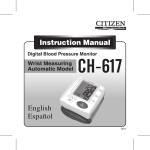
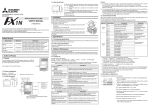
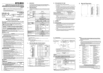
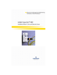
1
Standard
Remark
EN61000-6-4:2007
- Generic emission standard
Industrial environment
EN50081-2:1993
- Electromagnetic compatibility
Compliance with all relevant aspects of the standard.
• Radio-frequency electromagnetic field. Amplitude modulated
• Fast transients
• Electrostatic discharge
• Surges
• Voltage dips
• Voltage interruptions
• Radio-frequency common mode
• Power-frequency magnetic field
EN61000-6-2:2005
- Generic immunity standard
Industrial environment
FX2N-20PSU DC POWER SUPPLY UNIT
USER’S MANUAL
EN61131-2:2007
Programmable controllers
- Equipment requirements and tests
JY992D85101E
This manual contains text, diagrams and explanations which will guide the reader in the correct installation
and operation of the FX2N -20PSU DC power supply unit. It should be read and understood before
attempting to install or use the unit. Further information can be found in the FX series PLC hardware manuals.
Note’s on the symbology used in this manual
At various times through out this manual certain symbols will be used to highlight points of information which are intended to ensure the users personal safety and protect the integrity of the equipment. Whenever any of the following symbols are encountered, its associated note must be read
and understood. Each of the symbols used will now be listed with a brief description of its meaning.
Hardware warnings
1) Indicates that the identified danger WILL cause physical and property damage.
Compliance with all relevant aspects of the standard.
EMI
• Radiated Emission
• Conducted Emission
EMS
• Radiated electromagnetic field
• Fast Transient burst
• Electrostatic discharge
• High-energy surge
• Voltage drops and interruptions
• Conducted RF
• Power frequency magnetic field
•
•
•
FX2N-20PSU
EN61131-2:2007
Programmable controllers
- Equipment requirements and tests
The equipment has been assessed as a component for fitting
in a suitable enclosure which meets the requirements of
IEC 1010-1:1990 +A1:1992
The equipment has been assessed as a component for fitting
in a suitable enclosure which meets the requirements of
EN61131-2:2007
Insulation Resistance
5MΩ > at 500V DC, tested between all points, terminals and ground
Ground
Class D (100 Ω or less)*2
*1 The criterion is shown IEC61131-2.
*2
PLC/power
supply
Another
equipment
PLC/power
supply
Dedicated grounding
(best)
Another
equipment
Common grounding
(good)
PLC/power
supply
Another
equipment
Common grounding
(not allowed)
Input
Output
Rated voltage
100 to 240V AC
Allowable voltage
range
85 to 264V AC
Frequency
50/60Hz
Fuse rating
250V 3.15A (built in) Time-lag Fuse
Rush current
60A/200V AC maximum
Output voltage
24V DC ± 10%
Output current
2A (maximum), 0.2A (minimum)
(Derating is performed if ambient temperature exceeds 40 °C.)*1
Actuated when current becomes 110 - 160% or more, voltage drop
occurs automatic recovery
Protection against
overvoltage*3
Actuated when voltage becomes 110 - 140% or more, output shutsdown, no automatic recovery (diode clamp)
Power supply of sensor connected to input of PLC
•
Power supply of DC load connected to output of PLC
•
Power supply of display unit such as graphic operation terminal (GOT)
Output indication
Green LED(POWER) is lit while voltage is output.
Others
Serial/parallel operation with other power supply units is not allowed.
(See Section 6.3)
[Output derating]
N
52(2.05)
Unit:mm(inches)
4(0.16)
100
80
60
40
20
0
0
10
20
30
40
50 55
90(3.5)
Ambient temperature (°C)
This product is designed for use in industrial applications.
*1 The available output current varies depending on the ambient operating temperature. Use the FX2N20PSU in the available range in accordance with the output derating graph shown above.
98(3.85)
7.5(0.3)
2-φ4.5
(0.18)
L
Attention
DIN rail:35mm(1.38)
24V+
24V24V+
24V-
Programmable Controller (Open Type Equipment)
MELSEC FX2N series manufactured
60(2.36)
24V+ 24V24V+ 24V-
7.5(0.3)
4(0.16)
Authorized Representative in the European Community:
Mitsubishi Electric Europe B.V.Gothaer Str. 8, 40880 Ratingen, Germany
For the products above, PLCs manufactured before September 30th, 2013 are compliant with
EN61000-6-4(EN50081-2) and EN61000-6-2
after October 1st, 2013 are compliant with EN61131-2:2007
500V AC > 1 min, tested between all points, terminals and ground
Protection
function
•
FX2N-20PSU
1000Vp-p, 1microsecond, 30 - 100 Hz, tested by noise simulator
Dielectric Withstand
Voltage
The DC power supply unit FX2N-20PSU is available as the following applications.
Power supply of special extension block of PLC
from September 1st, 1999
Noise Immunity
10ms/100V AC
All examples and diagrams shown in this manual are intended only as an aid to understanding the text, not to guarantee operation. Mitsubishi Electric will accept no responsibility for
actual use of the product based on these illustrative examples.
Type:
Models:
147m/s2 Acceleration, Action Time: 11 ms
3 times in each direction X, Y, and Z
Protection against
overcurrent*2
Compliance with EC directive (CE Marking)
•
Shock Resistance
500mVp-p or less
Power supply of 24V DC power type PLC
Note
10 - 57 Hz: 0.035 mm Half Amplitude
57 - 150 Hz: 4.9 m/s2 Acceleration
Sweep Count for X, Y, Z: 10 times (80 min in each direction)
Holding time
2. EXTERNAL DIMENSION
•
Vibration Resistance*1
- DIN rail Mounting
Ripple noise
•
The following products have shown compliance through direct testing (of the identified standards below)
and design analysis (through the creation of a technical construction file) to the European Directive for
Electromagnetic Compatibility (2004/108/EC) when used as directed by the appropriate documentation.
10 - 57 Hz: 0.75 mm Half Amplitude
57 - 150 Hz: 9.8 m/s2 Acceleration
Sweep Count for X, Y, Z: 10 times (80 min in each direction)
1. INTRODUCTION
•
Requirement for Compliance with EMC directive
35 to 90% Relative Humidity, No condensation
*1
4. PERFORMANCE SPECOFOCATIONS
Under no circumstances will Mitsubishi Electric be liable or responsible for any consequential
damage that may arise as a result of the installation or use of this equipment.
This document does not guarantee that a mechanical system including this product will comply with the
following standards.
Compliance to EMC directive and LVD directive for the entire mechanical module should be checked by
the user/manufacturer. For more information please consult with your nearest Mitsubishi product provider.
Vibration Resistance
- Direct Mounting
Remark
IEC1010-1:1990/A1:1992
Safety requirements for electrical
equipment for measurement, control,
and laboratory use
- General requirements
This manual has been written to be used by trained and competent personnel. This is defined
by the European directives for machinery, low voltage and EMC.
Owing to the very great variety in possible application of this equipment, you must satisfy
yourself as to its suitability for your specific application.
storage Humidity
For the products above, PLCs manufactured before September 30th, 2013 are compliant with IEC1010-1
after October 1st, 2013 are compliant with EN61131-2:2007
Guidelines for the safety of the user and protection of the FX2N-20PSU DC
POWER SUPPLY UNIT
If in doubt at any stage during the installation of the FX2N-20PSU always consult a professional electrical engineer who is qualified and trained to the local and national standards. If in
doubt about the operation or use of the FX2N-20PSU please consult the nearest Mitsubishi
Electric distributor.
35 to 85% Relative Humidity, No condensation
Programmable Controller (Open Type Equipment)
MELSEC FX2N series manufactured
from September 1st, 1999
2) Indicates that the identified danger could POSSIBLY cause physical and property damage.
•
-20 to 70 °C (-4 to 158 °F)
Operating Humidity
The following products have shown compliance through direct testing (of the identified standards below)
and design analysis (through the creation of a technical construction file) to the European Directive for
Low Voltage (2006/95/EC) when used as directed by the appropriate documentation.
Type:
Models:
Description
0 to 55 °C (32 to 131 °F)
Storage Temperature
Requirement for Compliance with LVD directive
Standard
•
Item
Operating Temperature
Load ratio (%)
If in doubt at any stage during the installation of the FX2N-20PSU DC power supply unit always consult a
professional electrical engineer who is qualified and trained to the local and national standards.
3. GENERAL SPECIFICATIONS
Compliance with all relevant aspects of the standard.
• Emission-Enclosure port
• Emission-Low voltage AC mains port
• Emission-Telecommunications/network port
75(2.95)
Terminal screws: M3.5
Mass: Approximately 0.3 kg
Outer color: Munsell 0.08GY/7.64/0.81
*2 If the output current flows beyond the specified value, the overcurrent protection circuit is actuated
and the output voltage drops.
When the overcurrent status or the short-circuit status returns to acceptable levels, the output voltage
automatically recovers.
*3 If the voltage beyond the specified value is generated by an internal failure, etc., the output is shut
down so that high voltage is not output. When the voltage comes from a load circuit connected to an
output terminal or when overvoltage is input from the outside, the overvoltage protection circuit may
be actuated.
When the overvoltage protection circuit is actuated, the output is shut down and does not automatically recover. Ask for inspection and repair after such an occurance.
Standard
Remark
EN61000-6-4:2007
- Generic emission standard
Industrial environment
EN50081-2:1993
- Electromagnetic compatibility
Compliance with all relevant aspects of the standard.
• Radio-frequency electromagnetic field. Amplitude modulated
• Fast transients
• Electrostatic discharge
• Surges
• Voltage dips
• Voltage interruptions
• Radio-frequency common mode
• Power-frequency magnetic field
EN61000-6-2:2005
- Generic immunity standard
Industrial environment
FX2N-20PSU DC POWER SUPPLY UNIT
USER’S MANUAL
EN61131-2:2007
Programmable controllers
- Equipment requirements and tests
JY992D85101E
This manual contains text, diagrams and explanations which will guide the reader in the correct installation
and operation of the FX2N -20PSU DC power supply unit. It should be read and understood before
attempting to install or use the unit. Further information can be found in the FX series PLC hardware manuals.
Note’s on the symbology used in this manual
At various times through out this manual certain symbols will be used to highlight points of information which are intended to ensure the users personal safety and protect the integrity of the equipment. Whenever any of the following symbols are encountered, its associated note must be read
and understood. Each of the symbols used will now be listed with a brief description of its meaning.
Hardware warnings
1) Indicates that the identified danger WILL cause physical and property damage.
Compliance with all relevant aspects of the standard.
EMI
• Radiated Emission
• Conducted Emission
EMS
• Radiated electromagnetic field
• Fast Transient burst
• Electrostatic discharge
• High-energy surge
• Voltage drops and interruptions
• Conducted RF
• Power frequency magnetic field
•
•
•
FX2N-20PSU
EN61131-2:2007
Programmable controllers
- Equipment requirements and tests
The equipment has been assessed as a component for fitting
in a suitable enclosure which meets the requirements of
IEC 1010-1:1990 +A1:1992
The equipment has been assessed as a component for fitting
in a suitable enclosure which meets the requirements of
EN61131-2:2007
Insulation Resistance
5MΩ > at 500V DC, tested between all points, terminals and ground
Ground
Class D (100 Ω or less)*2
*1 The criterion is shown IEC61131-2.
*2
PLC/power
supply
Another
equipment
PLC/power
supply
Dedicated grounding
(best)
Another
equipment
Common grounding
(good)
PLC/power
supply
Another
equipment
Common grounding
(not allowed)
Input
Output
Rated voltage
100 to 240V AC
Allowable voltage
range
85 to 264V AC
Frequency
50/60Hz
Fuse rating
250V 3.15A (built in) Time-lag Fuse
Rush current
60A/200V AC maximum
Output voltage
24V DC ± 10%
Output current
2A (maximum), 0.2A (minimum)
(Derating is performed if ambient temperature exceeds 40 °C.)*1
Actuated when current becomes 110 - 160% or more, voltage drop
occurs automatic recovery
Protection against
overvoltage*3
Actuated when voltage becomes 110 - 140% or more, output shutsdown, no automatic recovery (diode clamp)
Power supply of sensor connected to input of PLC
•
Power supply of DC load connected to output of PLC
•
Power supply of display unit such as graphic operation terminal (GOT)
Output indication
Green LED(POWER) is lit while voltage is output.
Others
Serial/parallel operation with other power supply units is not allowed.
(See Section 6.3)
[Output derating]
N
52(2.05)
Unit:mm(inches)
4(0.16)
100
80
60
40
20
0
0
10
20
30
40
50 55
90(3.5)
Ambient temperature (°C)
This product is designed for use in industrial applications.
*1 The available output current varies depending on the ambient operating temperature. Use the FX2N20PSU in the available range in accordance with the output derating graph shown above.
98(3.85)
7.5(0.3)
2-φ4.5
(0.18)
L
Attention
DIN rail:35mm(1.38)
24V+
24V24V+
24V-
Programmable Controller (Open Type Equipment)
MELSEC FX2N series manufactured
60(2.36)
24V+ 24V24V+ 24V-
7.5(0.3)
4(0.16)
Authorized Representative in the European Community:
Mitsubishi Electric Europe B.V.Gothaer Str. 8, 40880 Ratingen, Germany
For the products above, PLCs manufactured before September 30th, 2013 are compliant with
EN61000-6-4(EN50081-2) and EN61000-6-2
after October 1st, 2013 are compliant with EN61131-2:2007
500V AC > 1 min, tested between all points, terminals and ground
Protection
function
•
FX2N-20PSU
1000Vp-p, 1microsecond, 30 - 100 Hz, tested by noise simulator
Dielectric Withstand
Voltage
The DC power supply unit FX2N-20PSU is available as the following applications.
Power supply of special extension block of PLC
from September 1st, 1999
Noise Immunity
10ms/100V AC
All examples and diagrams shown in this manual are intended only as an aid to understanding the text, not to guarantee operation. Mitsubishi Electric will accept no responsibility for
actual use of the product based on these illustrative examples.
Type:
Models:
147m/s2 Acceleration, Action Time: 11 ms
3 times in each direction X, Y, and Z
Protection against
overcurrent*2
Compliance with EC directive (CE Marking)
•
Shock Resistance
500mVp-p or less
Power supply of 24V DC power type PLC
Note
10 - 57 Hz: 0.035 mm Half Amplitude
57 - 150 Hz: 4.9 m/s2 Acceleration
Sweep Count for X, Y, Z: 10 times (80 min in each direction)
Holding time
2. EXTERNAL DIMENSION
•
Vibration Resistance*1
- DIN rail Mounting
Ripple noise
•
The following products have shown compliance through direct testing (of the identified standards below)
and design analysis (through the creation of a technical construction file) to the European Directive for
Electromagnetic Compatibility (2004/108/EC) when used as directed by the appropriate documentation.
10 - 57 Hz: 0.75 mm Half Amplitude
57 - 150 Hz: 9.8 m/s2 Acceleration
Sweep Count for X, Y, Z: 10 times (80 min in each direction)
1. INTRODUCTION
•
Requirement for Compliance with EMC directive
35 to 90% Relative Humidity, No condensation
*1
4. PERFORMANCE SPECOFOCATIONS
Under no circumstances will Mitsubishi Electric be liable or responsible for any consequential
damage that may arise as a result of the installation or use of this equipment.
This document does not guarantee that a mechanical system including this product will comply with the
following standards.
Compliance to EMC directive and LVD directive for the entire mechanical module should be checked by
the user/manufacturer. For more information please consult with your nearest Mitsubishi product provider.
Vibration Resistance
- Direct Mounting
Remark
IEC1010-1:1990/A1:1992
Safety requirements for electrical
equipment for measurement, control,
and laboratory use
- General requirements
This manual has been written to be used by trained and competent personnel. This is defined
by the European directives for machinery, low voltage and EMC.
Owing to the very great variety in possible application of this equipment, you must satisfy
yourself as to its suitability for your specific application.
storage Humidity
For the products above, PLCs manufactured before September 30th, 2013 are compliant with IEC1010-1
after October 1st, 2013 are compliant with EN61131-2:2007
Guidelines for the safety of the user and protection of the FX2N-20PSU DC
POWER SUPPLY UNIT
If in doubt at any stage during the installation of the FX2N-20PSU always consult a professional electrical engineer who is qualified and trained to the local and national standards. If in
doubt about the operation or use of the FX2N-20PSU please consult the nearest Mitsubishi
Electric distributor.
35 to 85% Relative Humidity, No condensation
Programmable Controller (Open Type Equipment)
MELSEC FX2N series manufactured
from September 1st, 1999
2) Indicates that the identified danger could POSSIBLY cause physical and property damage.
•
-20 to 70 °C (-4 to 158 °F)
Operating Humidity
The following products have shown compliance through direct testing (of the identified standards below)
and design analysis (through the creation of a technical construction file) to the European Directive for
Low Voltage (2006/95/EC) when used as directed by the appropriate documentation.
Type:
Models:
Description
0 to 55 °C (32 to 131 °F)
Storage Temperature
Requirement for Compliance with LVD directive
Standard
•
Item
Operating Temperature
Load ratio (%)
If in doubt at any stage during the installation of the FX2N-20PSU DC power supply unit always consult a
professional electrical engineer who is qualified and trained to the local and national standards.
3. GENERAL SPECIFICATIONS
Compliance with all relevant aspects of the standard.
• Emission-Enclosure port
• Emission-Low voltage AC mains port
• Emission-Telecommunications/network port
75(2.95)
Terminal screws: M3.5
Mass: Approximately 0.3 kg
Outer color: Munsell 0.08GY/7.64/0.81
*2 If the output current flows beyond the specified value, the overcurrent protection circuit is actuated
and the output voltage drops.
When the overcurrent status or the short-circuit status returns to acceptable levels, the output voltage
automatically recovers.
*3 If the voltage beyond the specified value is generated by an internal failure, etc., the output is shut
down so that high voltage is not output. When the voltage comes from a load circuit connected to an
output terminal or when overvoltage is input from the outside, the overvoltage protection circuit may
be actuated.
When the overvoltage protection circuit is actuated, the output is shut down and does not automatically recover. Ask for inspection and repair after such an occurance.
✩ Never connect the FX2N-20PSU serially to another power supply unit.
5. INSTALLATION
Sink inputs (+ve S/S)
FX2N-20PSU
Cautions on installation
•
•
•
Sensor 1
Use the unit in the environment for the general specifications described in Section 3 in the manual.
Never use the unit in a place with dust, soot, conductive dusts, corrosive gas or flammable gas,
place exposed to high temperature, dew condensation, rain and wind, or in a place exposed to
vibration or impact.
If the unit is used in such a place, electrical shock, fire, malfunction, damages in the unit or
deterioration of the unit may be caused.
Sensor 2
85 to 264V AC
24+ 24-
L
N
24V 0V
X1
S/S
X2
X5
Max.
6.8mm
(0.27")
✩ Tighten the terminals to a torque of 0.5 to 0.8 Nxm.
Do not tighten terminal screws with a torque outside the above-mentioned range. Failure to do so may
cause equipment failures or malfunctions.
[Installation direction]
[Crimp-style terminal]
Service power
supply
-
24+ 24-
24V
0V
7. TROUBLESHOOTING
When it is suspected that the FX2N-20PSU is not normally operating, check the following items.
PLC
24+ 24-
•
Check the POWER LED status.
Note
✩ Use crimp-style terminals of the dimensions shown in the figure below.
FX PLC
X7
FX2N-20PSU
After finishing installation, remove a dust preventing sheet adhered on the ventilation window.
If the sheet remains attached, fire, failure or malfunction may be caused.
✩ In order to prevent temperature rise, never install the unit on the floor surface, on the ceiling surface or
in the vertical direction.
Make sure to install the unit on a panel face in the horizontal direction as shown in the figure below.
+
FX2N-20PSU
Class D
grounding
Never drop cutting chips or electric wire chips into the ventilation window while drilling screw
holes or wiring cables.
Such chips may cause fire, failure or malfunction.
✩ During the installation/wiring work, place a dust preventing sheet on the ventilation window.
FX2N-20PSU or
another power
supply unit
[When the POWER LED is extinguished]
6.2 When FX2N-20PSU is used together with 24V DC service power supply built in PLC
-
In the AC power type FX PLC, a 24V DC service power supply is built.
When using the FX2N-20PSU and the service power supply together, connect the "24-" terminal of the
FX2N-20PSU and the "COM" terminal on the minus side of the service power supply as shown in the figure below.
-
Check the input voltage of the FX2N-20PSU.
If any abnormality is detected → Input the specified supply voltage.
Disconnect the wiring from the output terminals "24+" and "24-".
If the POWER LED lights → The overcurrent protection circuit (See Section 4) is actuated.
Investigate the load connected to the output terminals.
If the POWER LED remains extinguished → The overvoltage protection circuit (See Section 4)
may be actuated. Ask for inspection and repair.
Source inputs (-ve S/S)
Sensor 1
[When the POWER LED is lit]
Sensor 2
85 to 264V AC
FX2N-20PSU is normal.
Max.
6.8mm
(0.27")
For M3.5(0.14")
Class D
grounding
L
N
L
24+ 24-
24V 0V
S/S
X1
X2
X5
X7
Sensor 1
Sensor 2
Connect the minus line to share it.
Cautions on wiring
•
N
PLC
24V
Service
power supply
FX2N-20PSU
6. WIRING
The overcurrent protection circuit and the overvoltage protection circuit are built in the FX2N-20PSU.
If such a protection circuit is actuated, the output voltage drops or is shut down. For details, refer to
Section 4.
•
Make sure to shut down the power supplies of all phases on the outside before starting installation or wiring.
If the power supplies are not shut down, you may get electrical shock or the unit may be damaged.
•
Make sure to attach terminal covers offered as accessories before supplying power and starting operation after the installation/wiring work.
•
The rated temperature of the cable should be 80°C or more.
•
Correctly supply power to the PLC in accordance with "Cautions on Safety" described in the
manual of the PLC.
If power is not correctly supplied, the unit may be damaged.
•
Connect the wiring of the DC power supply to dedicated terminals as described in this manual.
If the AC power supply is connected to a DC power terminal, the unit may be burnt.
•
Never perform external wiring to unused terminals
•
Perform Class 3 grounding to the grounding terminal in the unit. However, never perform common grounding (See Section 3) with a strong power system.
•
Sink inputs (+ve S/S)
This manual confers no industrial property rights or any rights of any other kind, nor does it
confer any patent licenses. Mitsubishi Electric Corporation cannot be held responsible for any
problems involving industrial property rights which may occur as a result of using the contents
noted in this manual.
85 to 264V AC
Class D
grounding
Warranty
L
N
L
24V 0V
S/S
X1
X2
X5
X7
PLC
FX2N-20PSU
. Such wiring may damage the unit.
N
24V
Service
power supply
24+ 24-
Mitsubishi will not be held liable for damage caused by factors found not to be the cause of
Mitsubishi; opportunity loss or lost profits caused by faults in the Mitsubishi products; damage,
secondary damage, accident compensation caused by special factors unpredictable by Mitsubishi;
damages to products other than Mitsubishi products; and to other duties.
For safe use
•
Connect the minus line to share it.
6.3 Cautions
6.1 When FX2N-20PSU is connected to 24V DC power type PLC
•
Cautions on design
Source inputs (-ve S/S)
•
Sensor 1
Sensor 2
85 to 264V AC
Never connect in serial nor parallel the DC output terminals of the FX2N-20PSU to another
power supply unit.
Such a connection may damage the unit.
•
This product has been manufactured as a general-purpose part for general industries, and has
not been designed or manufactured to be incorporated in a device or system used in purposes
related to human life.
Before using the product for special purposes such as nuclear power, electric power,
aerospace, medicine or passenger movement vehicles, consult with Mitsubishi Electric.
This product has been manufactured under strict quality control. However when installing the
product where major accidents or losses could occur if the product fails, install appropriate
backup or failsafe functions in the system.
✩ Never connect the FX2N-20PSU in parallel to another power supply unit.
Class D
grounding
FX2N-20PSU
L
N
24V 0V
S/S
X1
X2
X5
X7
24+ 24-
FX2N-20PSU or
another power
supply unit
+
-
FX2N-20PSU
Manual number : JY992D85101
FX PLC
Service power
supply
24+ 24-
24V
Manual revision : E
0V
Date
FX2N-20PSU
24+ 24-
: April 2015
PLC
HEAD OFFICE : TOKYO BUILDING, 2-7-3 MARUNOUCHI, CHIYODA-KU,TOKYO 100-8310, JAPAN
JY992D85101E
Effective April 2015
Specifications are subject to change without notice.
Standard
Remark
EN61000-6-4:2007
- Generic emission standard
Industrial environment
EN50081-2:1993
- Electromagnetic compatibility
Compliance with all relevant aspects of the standard.
• Radio-frequency electromagnetic field. Amplitude modulated
• Fast transients
• Electrostatic discharge
• Surges
• Voltage dips
• Voltage interruptions
• Radio-frequency common mode
• Power-frequency magnetic field
EN61000-6-2:2005
- Generic immunity standard
Industrial environment
FX2N-20PSU DC POWER SUPPLY UNIT
USER’S MANUAL
EN61131-2:2007
Programmable controllers
- Equipment requirements and tests
JY992D85101E
This manual contains text, diagrams and explanations which will guide the reader in the correct installation
and operation of the FX2N -20PSU DC power supply unit. It should be read and understood before
attempting to install or use the unit. Further information can be found in the FX series PLC hardware manuals.
Note’s on the symbology used in this manual
At various times through out this manual certain symbols will be used to highlight points of information which are intended to ensure the users personal safety and protect the integrity of the equipment. Whenever any of the following symbols are encountered, its associated note must be read
and understood. Each of the symbols used will now be listed with a brief description of its meaning.
Hardware warnings
1) Indicates that the identified danger WILL cause physical and property damage.
Compliance with all relevant aspects of the standard.
EMI
• Radiated Emission
• Conducted Emission
EMS
• Radiated electromagnetic field
• Fast Transient burst
• Electrostatic discharge
• High-energy surge
• Voltage drops and interruptions
• Conducted RF
• Power frequency magnetic field
•
•
•
FX2N-20PSU
EN61131-2:2007
Programmable controllers
- Equipment requirements and tests
The equipment has been assessed as a component for fitting
in a suitable enclosure which meets the requirements of
IEC 1010-1:1990 +A1:1992
The equipment has been assessed as a component for fitting
in a suitable enclosure which meets the requirements of
EN61131-2:2007
Insulation Resistance
5MΩ > at 500V DC, tested between all points, terminals and ground
Ground
Class D (100 Ω or less)*2
*1 The criterion is shown IEC61131-2.
*2
PLC/power
supply
Another
equipment
PLC/power
supply
Dedicated grounding
(best)
Another
equipment
Common grounding
(good)
PLC/power
supply
Another
equipment
Common grounding
(not allowed)
Input
Output
Rated voltage
100 to 240V AC
Allowable voltage
range
85 to 264V AC
Frequency
50/60Hz
Fuse rating
250V 3.15A (built in) Time-lag Fuse
Rush current
60A/200V AC maximum
Output voltage
24V DC ± 10%
Output current
2A (maximum), 0.2A (minimum)
(Derating is performed if ambient temperature exceeds 40 °C.)*1
Actuated when current becomes 110 - 160% or more, voltage drop
occurs automatic recovery
Protection against
overvoltage*3
Actuated when voltage becomes 110 - 140% or more, output shutsdown, no automatic recovery (diode clamp)
Power supply of sensor connected to input of PLC
•
Power supply of DC load connected to output of PLC
•
Power supply of display unit such as graphic operation terminal (GOT)
Output indication
Green LED(POWER) is lit while voltage is output.
Others
Serial/parallel operation with other power supply units is not allowed.
(See Section 6.3)
[Output derating]
N
52(2.05)
Unit:mm(inches)
4(0.16)
100
80
60
40
20
0
0
10
20
30
40
50 55
90(3.5)
Ambient temperature (°C)
This product is designed for use in industrial applications.
*1 The available output current varies depending on the ambient operating temperature. Use the FX2N20PSU in the available range in accordance with the output derating graph shown above.
98(3.85)
7.5(0.3)
2-φ4.5
(0.18)
L
Attention
DIN rail:35mm(1.38)
24V+
24V24V+
24V-
Programmable Controller (Open Type Equipment)
MELSEC FX2N series manufactured
60(2.36)
24V+ 24V24V+ 24V-
7.5(0.3)
4(0.16)
Authorized Representative in the European Community:
Mitsubishi Electric Europe B.V.Gothaer Str. 8, 40880 Ratingen, Germany
For the products above, PLCs manufactured before September 30th, 2013 are compliant with
EN61000-6-4(EN50081-2) and EN61000-6-2
after October 1st, 2013 are compliant with EN61131-2:2007
500V AC > 1 min, tested between all points, terminals and ground
Protection
function
•
FX2N-20PSU
1000Vp-p, 1microsecond, 30 - 100 Hz, tested by noise simulator
Dielectric Withstand
Voltage
The DC power supply unit FX2N-20PSU is available as the following applications.
Power supply of special extension block of PLC
from September 1st, 1999
Noise Immunity
10ms/100V AC
All examples and diagrams shown in this manual are intended only as an aid to understanding the text, not to guarantee operation. Mitsubishi Electric will accept no responsibility for
actual use of the product based on these illustrative examples.
Type:
Models:
147m/s2 Acceleration, Action Time: 11 ms
3 times in each direction X, Y, and Z
Protection against
overcurrent*2
Compliance with EC directive (CE Marking)
•
Shock Resistance
500mVp-p or less
Power supply of 24V DC power type PLC
Note
10 - 57 Hz: 0.035 mm Half Amplitude
57 - 150 Hz: 4.9 m/s2 Acceleration
Sweep Count for X, Y, Z: 10 times (80 min in each direction)
Holding time
2. EXTERNAL DIMENSION
•
Vibration Resistance*1
- DIN rail Mounting
Ripple noise
•
The following products have shown compliance through direct testing (of the identified standards below)
and design analysis (through the creation of a technical construction file) to the European Directive for
Electromagnetic Compatibility (2004/108/EC) when used as directed by the appropriate documentation.
10 - 57 Hz: 0.75 mm Half Amplitude
57 - 150 Hz: 9.8 m/s2 Acceleration
Sweep Count for X, Y, Z: 10 times (80 min in each direction)
1. INTRODUCTION
•
Requirement for Compliance with EMC directive
35 to 90% Relative Humidity, No condensation
*1
4. PERFORMANCE SPECOFOCATIONS
Under no circumstances will Mitsubishi Electric be liable or responsible for any consequential
damage that may arise as a result of the installation or use of this equipment.
This document does not guarantee that a mechanical system including this product will comply with the
following standards.
Compliance to EMC directive and LVD directive for the entire mechanical module should be checked by
the user/manufacturer. For more information please consult with your nearest Mitsubishi product provider.
Vibration Resistance
- Direct Mounting
Remark
IEC1010-1:1990/A1:1992
Safety requirements for electrical
equipment for measurement, control,
and laboratory use
- General requirements
This manual has been written to be used by trained and competent personnel. This is defined
by the European directives for machinery, low voltage and EMC.
Owing to the very great variety in possible application of this equipment, you must satisfy
yourself as to its suitability for your specific application.
storage Humidity
For the products above, PLCs manufactured before September 30th, 2013 are compliant with IEC1010-1
after October 1st, 2013 are compliant with EN61131-2:2007
Guidelines for the safety of the user and protection of the FX2N-20PSU DC
POWER SUPPLY UNIT
If in doubt at any stage during the installation of the FX2N-20PSU always consult a professional electrical engineer who is qualified and trained to the local and national standards. If in
doubt about the operation or use of the FX2N-20PSU please consult the nearest Mitsubishi
Electric distributor.
35 to 85% Relative Humidity, No condensation
Programmable Controller (Open Type Equipment)
MELSEC FX2N series manufactured
from September 1st, 1999
2) Indicates that the identified danger could POSSIBLY cause physical and property damage.
•
-20 to 70 °C (-4 to 158 °F)
Operating Humidity
The following products have shown compliance through direct testing (of the identified standards below)
and design analysis (through the creation of a technical construction file) to the European Directive for
Low Voltage (2006/95/EC) when used as directed by the appropriate documentation.
Type:
Models:
Description
0 to 55 °C (32 to 131 °F)
Storage Temperature
Requirement for Compliance with LVD directive
Standard
•
Item
Operating Temperature
Load ratio (%)
If in doubt at any stage during the installation of the FX2N-20PSU DC power supply unit always consult a
professional electrical engineer who is qualified and trained to the local and national standards.
3. GENERAL SPECIFICATIONS
Compliance with all relevant aspects of the standard.
• Emission-Enclosure port
• Emission-Low voltage AC mains port
• Emission-Telecommunications/network port
75(2.95)
Terminal screws: M3.5
Mass: Approximately 0.3 kg
Outer color: Munsell 0.08GY/7.64/0.81
*2 If the output current flows beyond the specified value, the overcurrent protection circuit is actuated
and the output voltage drops.
When the overcurrent status or the short-circuit status returns to acceptable levels, the output voltage
automatically recovers.
*3 If the voltage beyond the specified value is generated by an internal failure, etc., the output is shut
down so that high voltage is not output. When the voltage comes from a load circuit connected to an
output terminal or when overvoltage is input from the outside, the overvoltage protection circuit may
be actuated.
When the overvoltage protection circuit is actuated, the output is shut down and does not automatically recover. Ask for inspection and repair after such an occurance.
✩ Never connect the FX2N-20PSU serially to another power supply unit.
5. INSTALLATION
Sink inputs (+ve S/S)
FX2N-20PSU
Cautions on installation
•
•
•
Sensor 1
Use the unit in the environment for the general specifications described in Section 3 in the manual.
Never use the unit in a place with dust, soot, conductive dusts, corrosive gas or flammable gas,
place exposed to high temperature, dew condensation, rain and wind, or in a place exposed to
vibration or impact.
If the unit is used in such a place, electrical shock, fire, malfunction, damages in the unit or
deterioration of the unit may be caused.
Sensor 2
85 to 264V AC
24+ 24-
L
N
24V 0V
X1
S/S
X2
X5
Max.
6.8mm
(0.27")
✩ Tighten the terminals to a torque of 0.5 to 0.8 Nxm.
Do not tighten terminal screws with a torque outside the above-mentioned range. Failure to do so may
cause equipment failures or malfunctions.
[Installation direction]
[Crimp-style terminal]
Service power
supply
-
24+ 24-
24V
0V
7. TROUBLESHOOTING
When it is suspected that the FX2N-20PSU is not normally operating, check the following items.
PLC
24+ 24-
•
Check the POWER LED status.
Note
✩ Use crimp-style terminals of the dimensions shown in the figure below.
FX PLC
X7
FX2N-20PSU
After finishing installation, remove a dust preventing sheet adhered on the ventilation window.
If the sheet remains attached, fire, failure or malfunction may be caused.
✩ In order to prevent temperature rise, never install the unit on the floor surface, on the ceiling surface or
in the vertical direction.
Make sure to install the unit on a panel face in the horizontal direction as shown in the figure below.
+
FX2N-20PSU
Class D
grounding
Never drop cutting chips or electric wire chips into the ventilation window while drilling screw
holes or wiring cables.
Such chips may cause fire, failure or malfunction.
✩ During the installation/wiring work, place a dust preventing sheet on the ventilation window.
FX2N-20PSU or
another power
supply unit
[When the POWER LED is extinguished]
6.2 When FX2N-20PSU is used together with 24V DC service power supply built in PLC
-
In the AC power type FX PLC, a 24V DC service power supply is built.
When using the FX2N-20PSU and the service power supply together, connect the "24-" terminal of the
FX2N-20PSU and the "COM" terminal on the minus side of the service power supply as shown in the figure below.
-
Check the input voltage of the FX2N-20PSU.
If any abnormality is detected → Input the specified supply voltage.
Disconnect the wiring from the output terminals "24+" and "24-".
If the POWER LED lights → The overcurrent protection circuit (See Section 4) is actuated.
Investigate the load connected to the output terminals.
If the POWER LED remains extinguished → The overvoltage protection circuit (See Section 4)
may be actuated. Ask for inspection and repair.
Source inputs (-ve S/S)
Sensor 1
[When the POWER LED is lit]
Sensor 2
85 to 264V AC
FX2N-20PSU is normal.
Max.
6.8mm
(0.27")
For M3.5(0.14")
Class D
grounding
L
N
L
24+ 24-
24V 0V
S/S
X1
X2
X5
X7
Sensor 1
Sensor 2
Connect the minus line to share it.
Cautions on wiring
•
N
PLC
24V
Service
power supply
FX2N-20PSU
6. WIRING
The overcurrent protection circuit and the overvoltage protection circuit are built in the FX2N-20PSU.
If such a protection circuit is actuated, the output voltage drops or is shut down. For details, refer to
Section 4.
•
Make sure to shut down the power supplies of all phases on the outside before starting installation or wiring.
If the power supplies are not shut down, you may get electrical shock or the unit may be damaged.
•
Make sure to attach terminal covers offered as accessories before supplying power and starting operation after the installation/wiring work.
•
The rated temperature of the cable should be 80°C or more.
•
Correctly supply power to the PLC in accordance with "Cautions on Safety" described in the
manual of the PLC.
If power is not correctly supplied, the unit may be damaged.
•
Connect the wiring of the DC power supply to dedicated terminals as described in this manual.
If the AC power supply is connected to a DC power terminal, the unit may be burnt.
•
Never perform external wiring to unused terminals
•
Perform Class 3 grounding to the grounding terminal in the unit. However, never perform common grounding (See Section 3) with a strong power system.
•
Sink inputs (+ve S/S)
This manual confers no industrial property rights or any rights of any other kind, nor does it
confer any patent licenses. Mitsubishi Electric Corporation cannot be held responsible for any
problems involving industrial property rights which may occur as a result of using the contents
noted in this manual.
85 to 264V AC
Class D
grounding
Warranty
L
N
L
24V 0V
S/S
X1
X2
X5
X7
PLC
FX2N-20PSU
. Such wiring may damage the unit.
N
24V
Service
power supply
24+ 24-
Mitsubishi will not be held liable for damage caused by factors found not to be the cause of
Mitsubishi; opportunity loss or lost profits caused by faults in the Mitsubishi products; damage,
secondary damage, accident compensation caused by special factors unpredictable by Mitsubishi;
damages to products other than Mitsubishi products; and to other duties.
For safe use
•
Connect the minus line to share it.
6.3 Cautions
6.1 When FX2N-20PSU is connected to 24V DC power type PLC
•
Cautions on design
Source inputs (-ve S/S)
•
Sensor 1
Sensor 2
85 to 264V AC
Never connect in serial nor parallel the DC output terminals of the FX2N-20PSU to another
power supply unit.
Such a connection may damage the unit.
•
This product has been manufactured as a general-purpose part for general industries, and has
not been designed or manufactured to be incorporated in a device or system used in purposes
related to human life.
Before using the product for special purposes such as nuclear power, electric power,
aerospace, medicine or passenger movement vehicles, consult with Mitsubishi Electric.
This product has been manufactured under strict quality control. However when installing the
product where major accidents or losses could occur if the product fails, install appropriate
backup or failsafe functions in the system.
✩ Never connect the FX2N-20PSU in parallel to another power supply unit.
Class D
grounding
FX2N-20PSU
L
N
24V 0V
S/S
X1
X2
X5
X7
24+ 24-
FX2N-20PSU or
another power
supply unit
+
-
FX2N-20PSU
Manual number : JY992D85101
FX PLC
Service power
supply
24+ 24-
24V
Manual revision : E
0V
Date
FX2N-20PSU
24+ 24-
: April 2015
PLC
HEAD OFFICE : TOKYO BUILDING, 2-7-3 MARUNOUCHI, CHIYODA-KU,TOKYO 100-8310, JAPAN
JY992D85101E
Effective April 2015
Specifications are subject to change without notice.