1
Table of Contents
Chapter 1 ...................................................................................................................................... 1
Overview ......................................................................................................................................1
1.1 Terms.....................................................................................................................................1
1.2 Chapter description................................................................................................................1
1.3 Prerequisites ..........................................................................................................................1
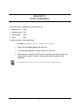
1.4 Equipment and system requirements....................................................................................2
1.5 Document conventions ..........................................................................................................3
Chapter 2 ...................................................................................................................................... 4
Login and Password ....................................................................................................................4
2.1 Security Profile .......................................................................................................................4
2.2 Access Level..........................................................................................................................4
Chapter 3 ...................................................................................................................................... 5
Application screen description.....................................................................................................5
3.1 Pull down Menu bar ...............................................................................................................6
3.2 Screen selection buttons .......................................................................................................6
3.3 Work Area ..............................................................................................................................7
Chapter 4 ...................................................................................................................................... 8
Connection screen.......................................................................................................................8
4.1 Main Connection Display Screen ..........................................................................................8
4.2 Connection management.......................................................................................................9
4.2.1 Site selection table......................................................................................................9
4.2.2 Preview Windows .......................................................................................................9
4.2.3 Connection button.......................................................................................................9
4.2.4 Site Search .................................................................................................................9
4.3 Site management.................................................................................................................10
4.3.1 Field description........................................................................................................10
4.3.2 Adding, removing and modifying sites .....................................................................11
4.3.2.1 Adding a new site ........................................................................................ 11
4.3.2.2 Site data modification .................................................................................. 12
i
Table of Contents (continued)
4.3.2.3 Removing a site ........................................................................................... 13
4.3.3 Save preview ............................................................................................................13
4.4 Camera configuration ..........................................................................................................14
4.4.1 Field description........................................................................................................14
4.4.2 Adding, removing and modifying cameras ...............................................................15
4.4.2.1 Adding a new camera.................................................................................. 15
4.4.2.2 Camera data modification............................................................................ 16
4.4.2.3 Removing a camera..................................................................................... 16
4.4.3 Defined cameras table..............................................................................................16
4.5 Connection configuration .....................................................................................................17
4.5.1 Field description........................................................................................................17
4.5.2 Adding, removing and modifying connections .........................................................19
4.5.2.1 Adding a new connection ............................................................................ 19
4.5.2.2 Connection data modification ...................................................................... 20
4.5.2.3 Removing a connection ............................................................................... 20
4.5.3 Connection selection table .......................................................................................21
4.5.4 Outgoing calls configuration .....................................................................................21
4.5.4.1 Multilink configuration .................................................................................. 21
4.5.5 Incoming calls configuration .....................................................................................22
4.5.6 Limitations according to operating system ...............................................................24
4.6 Users management .............................................................................................................24
4.6.1 Field description........................................................................................................24
4.6.2 Adding, removing and modifying users....................................................................26
4.6.2.1 Adding a new user ....................................................................................... 26
4.6.2.2 User data modification ................................................................................. 27
4.6.2.3 Removing a user.......................................................................................... 27
4.6.3 Registered Users table .............................................................................................27
4.7 Security ................................................................................................................................27
4.7.1 Field description........................................................................................................27
4.7.2 Access level table .....................................................................................................28
4.7.3 Profiles ......................................................................................................................29
ii
Table of Contents (continued)
Chapter 5 ....................................................................................................................................30
Viewer screen ............................................................................................................................30
5.1 Screen layout .......................................................................................................................31
5.2 Inputs / outputs ....................................................................................................................31
5.3 Small displays ......................................................................................................................31
5.4 NxM Matrix control window ..................................................................................................32
5.5 Main display .........................................................................................................................34
5.6 Special video image displays ..............................................................................................35
5.7 Video control ........................................................................................................................35
5.8 Recording.............................................................................................................................36
5.9 Image adjustments...............................................................................................................36
5.10 VISCA Camera control and auto tracking feature .............................................................38
5.11 Remote camera control .....................................................................................................38
5.12 Camera control using the keyboard ..................................................................................39
5.13 Snapshot ............................................................................................................................39
5.14 Full screen visualization.....................................................................................................40
Chapter 6 ....................................................................................................................................41
Sequences screen .....................................................................................................................41
6.1 Screen layout .......................................................................................................................41
6.2 Sequence access.................................................................................................................42
6.2.1 Calendar....................................................................................................................42
6.2.2 Timetable selection screen.......................................................................................42
6.2.3 Minutes timetable......................................................................................................43
6.2.4 Sequence table .........................................................................................................44
6.3 Sequence Sampling.............................................................................................................45
6.4 Sequence selection by content............................................................................................47
6.4.1 Visualizing sequences ..............................................................................................47
6.4.2 Sequence selection ..................................................................................................47
6.4.3 Sequence joining ......................................................................................................47
iii
Table of Contents (continued)
6.5 Visualization control .............................................................................................................47
6.6 Hard drive sequence management .....................................................................................48
6.7 Taking and editing snapshots ..............................................................................................50
Chapter 7 ....................................................................................................................................51
Control panel ..............................................................................................................................51
Chapter 8 ....................................................................................................................................52
Alarm manager...........................................................................................................................52
8.1 Alarm reception....................................................................................................................52
8.2 Screen layout .......................................................................................................................53
8.3 Field description...................................................................................................................53
8.4 Alarm button.........................................................................................................................54
8.5 False Alarm button...............................................................................................................54
8.6 Remote site connection window ..........................................................................................55
8.7 Connect button.....................................................................................................................55
8.8 Special cases.......................................................................................................................56
8.9 Alarm log ..............................................................................................................................57
Chapter 9 ....................................................................................................................................59
Log file and database backup....................................................................................................59
9.1 Log File ................................................................................................................................59
9.2 Database backup management...........................................................................................60
9.2.1 Creating a backup database in a fully programmed CyberView™ ..........................60
9.2.2 To load a backup database in a newly installed CyberView™: ...............................61
Appendix 1: Incoming calls configuration .......................................................................62
Appendix 2: Ports configuration..........................................................................................65
Appendix 3: Automatic configuration ................................................................................66
iv
Chapter 1
Overview
This manual provides software configuration, features, procedures, and software interface
information for CyberView™. To fully realize the benefits of this manual, users should have the
following:
!
CyberStation™—the remote controller, located on the customer surveilled premises.
CyberStation’s basic function is to transmit and eventually record video. It is also called
the transmitter.
!
CyberView™—the video management software suite for CyberStation™ Remote
Controller. CyberView™ displays video from one or more remote controllers. CyberView™
also receives and displays the alarms generated. It is also called the receiver.
1.1 Terms
In this manual, the terms receiver, video management software, software suite, application or
CyberView™ are used interchangeably to identify CyberView™. The terms, transmitter, remote
controller or CyberStation™ are used interchangeably to identify CyberStation™.
1.2 Chapter description
Each chapter describes the CyberView™ features, their configuration and application.
This manual does not describe the LAN/WAN networking concepts related to CyberStation™ or
any network device. Users unfamiliar with CyberView™ are invited to thoroughly read this
manual for installation and configuration information and procedures.
1.3 Prerequisites
Users familiar with basic ethernet (LAN) and wide area networks (WAN) communication
concepts, their terminology, and basic Internet technology, including browsers, will find this
manual easier to understand and follow. Preferably, users should also be familiar with PPP,
DSL, and TCP/IP concepts in Microsoft® Windows® operating systems.
1
Chapter 1 – Overview
1.4 Equipment and system requirements
A working configuration set-up requires the following equipment:
!
a CyberStation™ remote controller.
!
CyberView™ software and documentation distribution CD.
!
an RS232 console cable (one DB9 male and one DB9 female connectors in each end).
!
an RJ45 category 5 crossed ethernet cable or an existing ethernet LAN with at least two
RJ45 ports available in an ethernet Hub or Switch.
!
one DSL phone line for high speed communication and a DSL router/bridge with 4 port
Hub/Switch with at least at least two available RJ45 ports.
!
one phone line with dialup communication when used with the Securcomm Uniflex DC336B
Optional Modem Module. One Telco cable (length as required) & DB 25 male to DB 25
female cable.
A working configuration set-up requires these system requirements:
!
Pentium II processor with 64 Mb RAM (128 Mb RAM required for CyberView™).
!
Windows® 95, 98, NT or 2000).
!
Internet browser, such as Netscape Navigator or Microsoft® Explorer.
!
a 10 Mbps or 10/100 ethernet interface1.
1
Since CyberStation™ ethernet interface is 10Mbps, it should not be connected to “exclusive 100Mbps” LAN devices,
because no communications will be possible.
2
Chapter 1 – Overview
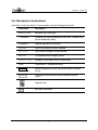
1.5 Document conventions
CyberView™ and CyberStation™ documentation uses the following conventions:
Convention
Description
Courier bold
Keywords and Commands
( Substitute )
Variables that must be replaced by their value. Variables may
also be displayed in italics.
< Optional >
Optional arguments or keywords.
{x|y|z}
One of many options must be selected.
{x+y+z}
One, more or all options can be selected.
Courier
Text displayed on the display monitor.
Courier italic
Examples of information that must be entered.
Listing
CyberStation™ configuration listing.
Button.
Buttons displayed on screen that can be clicked, using the
mouse.
Field.
Fields that require the user to enter information into the
system.
Important note.
Type
Key press commands.
3
Chapter 2
Login and Password
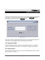
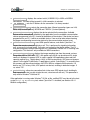
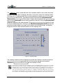
CyberView’s start window invites users to enter a user name and password for system database
authentication. To enter the data for authentication, either tab to the Accept button and
press enter, or use the mouse to click the Accept button.
FIGURE 1. LOGIN
Once access is granted, the login window displays the user’s Security profile and Access level.
These data are used to accept or deny the use of certain system resources.
2.1 Security Profile
The Security Profile grants the user access to certain system resources (e.g., to move PTZ
camera or record images in the hard drive. Also see Section 4.7 Security for more details).
2.2 Access Level
The access level is the amount of access a user has, and is dependant upon the user’s access
level (see Section 4.7 Security).
4
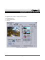
Chapter 3
Application screen description
The application main screen is composed of three sections:
!
pull down menu bar
!
screen selection buttons
!
work area
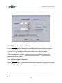
FIGURE 2. TYPICAL SCREEN APPLICATION
5
Chapter 3 – Application screen description
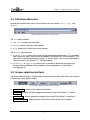
3.1 Pull down Menu bar
Located the top of the main screen, the pull-down menu bar contains: File, Help, and
Options.
FIGURE 3. MAIN SCREEN —PULL-DOWN MENU BAR
The File option contains:
!
Log file—displays the event table
!
Backup—makes a backup of the database
!
Help displays the CyberView’s version number
The Options menu contains:
!
Pending alarms—allows users to remove all unprocessed pending alarms. This command
does not remove alarms stored in the log database. (see Section 8.1 Alarm reception). This
command is useful when testing the system. To use this option, users must have privilege to
“Remove Alarms” (see Section 4.7.1 Field description)
!
Automatic configuration—Allows users to activate or deactivate the window or to
accept or deny modification of local database, when connected to a CyberStation™
(see Appendix 3).
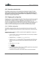
3.2 Screen selection buttons
The screen selection buttons, located below the pull down menu bar, contain the access buttons
to CyberView’s main display screens.
FIGURE 4. MAIN SCREEN —SCREEN SELECTION BUTTONS
!
Connection —access to the database information.
!
Viewer —visualize real time images transmitted by remote CyberStation™ systems.
!
Sequences —access sequences recorded in the remote CyberStation™ hard drives.
!
Control Panel —reserved and not used in the current version of this software.
6
6
Chapter 3 – Application screen description
!
Alarm Manager —screen where the alarms are received by the system. Next to the
Alarm Manager
button, is a numeric indicator of pending alarms and their color-coded
priority levels:
Red = maximum priority
Yellow = medium priority
Green = low priority
3.3 Work Area
The work area occupies most of the display screen, and is where the callup screens are
displayed.
7
7
Chapter 4
Connection screen
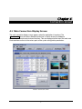
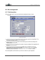
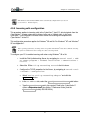
4.1 Main Connection Display Screen
The main connection display screen appears when the application is launched. The
Connection tab in the Screen Selection button bar is used to access the database
information in a simple and structured interface. Tabs are displayed at the top of the work area.
Each tab allows access to the various parts of the system configuration parameters.
FIGURE 5. CONNECTION SCREEN
8
Chapter 4 – Connection screen
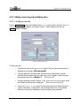
4.2 Connection management
4.2.1 Site selection table
The CyberStation™ remote controllers configured in this application are called sites. The site
selection table shows all sites entered into the database. Scrolling bars are provided to view all
table fields when the list extends beyond the window’s virtual borders.
Selecting a row selects its corresponding site. The selection is shadowed in blue. Its site
configuration parameters are accessed through tabs, which are located at the top.
4.2.2 Preview Windows
Preview windows are displayed to the right of the site selection table. Once a site is selected,
the preview widows will display the fixed images from the site’s pre-selected and configured
cameras selected with the Save Previewing button in the Sites tab.
4.2.3 Connection button
The Connect / Disconnect button is located at the top-right of the work area. When
clicked, the application connects to the selected site. Connection messages appear at the
bottom of the working area during the connection process. If the connection is successful, a
message appears with the name of the connected site, and the world icon, located in the
top-right corner, becomes an active animation. If the connection is unsuccessful, an error
message appears in the status bar, located at the bottom of the display screen.
4.2.4 Site Search
CyberView™ allows users to search for a specific site by full or partial name. To begin a search,
type the name in the field above the Search Site button, located to the left of the browsing
buttons, then click the Search Site button. If a match is found, it will be displayed and
selected in the site table.
9
Chapter 4 – Connection screen
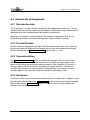
4.3 Site management
4.3.1 Field description
In the Sites tab screen, users can review the site configuration data as shown.
FIGURE 6. SITE SCREEN
!
Login and password —must be identical to the ones used in the CyberStation™ for
the system to accept a connection from CyberView™.
!
Default connection —shows the connection type used when connecting to the
remote system.
!
Connected Cameras —shows the number of cameras configured in the application for
this site.
!
Connected to extension board —notifies the user whether an alarm site
(supported by the system card) is connected to the remote system or not (see Error!
Reference source not found.). If it is, the Control Panel window is enabled.
The remaining fields are informative only, and have no effect on system operation.
10
Chapter 4 – Connection screen
4.3.2 Adding, removing and modifying sites
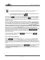
4.3.2.1 Adding a new site
Click the New entry button at the bottom of the Sites screen to add a new site. The Site
Configuration window appears, as shown in Figure 7. When adding a new site, the
Modify button is disabled.
FIGURE 7. ADDING A NEW SITE
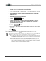
To add a new site:
1.
Type the site name in the Site name field. The new site name cannot be a
duplicate of an existing name in the database.
2.
Type the login name and password contained in the CyberStation™ remote
controller in the respective login and password fields. Users must type
the password twice for verification.
3.
Using the pull-down numeric selector, in the Connected cameras list, select
the number of cameras to be configured.
4.
In the Additional Fields panel, use the drop-down lists to select the type of
system, Input Points, Output points, and connected alarm site. The remaining
fields are used to store information, but do not effect system operation.
11
Chapter 4 – Connection screen
The four fields located directly under the Additional fields panel refer to the optional IPTV system’s
voice over IP feature. Documentation is provided in a separate software and firmware package set.
5.
Once all data has been entered, click the Add button to include the new site in
the system database. Otherwise, click Cancel .
After clicking the Add button, the new site configuration information is saved and displayed
for users to modify the new site, if necessary. After clicking the Add button, the connection
configuration screen is automatically activated (see Section 4.5 Connection configuration for
additional information).
If only a LAN connection will be used, only the CyberStation™ controller’s IP address is
required for data entry. The default values in the remaining fields do not need modification. If
using a MODEM or ISDN connection, enter the telephone number ( Dial number ) and the
unique communication circuit’s remote IP Address (see Note in Section 4.5.1 Field description).
Select the required communication Device in the device selection table, listing the available
communication choices programmed in the PC, located at the bottom of the window. The
default values in the remaining fields are adequate for standard communication and do not need
modification but change as required. For proper transmission, the Type connection must
be consistent with communication choice selected (Modem type for Dialup or ISDN type of
ISDN Communication).
Once all data has been entered, click the Accept button. Otherwise, click Cancel , if
unsure of some of the parameters.
4.3.2.2 Site data modification
Click the Modify button at the bottom of the Site configuration screen to modify
data. The Site Communication window appears. Any site data information fields can be
modified in this window. However, this window does not allow users to delete the site name. To
delete the site name, users must delete the entire site and re-enter its information with the new
name.
To modify the default connection selection, click the Selection button, located to the right of
the
Default connection field. The Default Connection window appears,
containing the table of connections defined for the system. Select the new default connection
from the table.
12
Chapter 4 – Connection screen
FIGURE 8. MODIFYING A SITE
4.3.2.3 Removing a site
To remove a site from the application, select the site and click the Remove button at the
bottom of the Site configuration screen. Site information and any camera or connection
associated to the site is deleted from the system.
4.3.3 Save preview
The Save Previewing button allows users to store an image of the camera view shown in
the Viewer screen main display in the database as a camera preview. This action can be
performed for each site camera to more easily remember their locations. This button is enabled
only when the connection with the remote system is active.
13
Chapter 4 – Connection screen
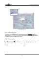
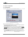
4.4 Camera configuration
4.4.1 Field description
Once a site is selected, access the camera configuration by clicking the Cameras Config tab.
FIGURE 9. CAMERA CONFIGURATION SCREEN
Below, is an explanation of the fields in the Cameras Config window:
!
Associated name —The name given to each camera as an identifier for CyberView™
(max 8 characters). Do not duplicate names in this field.
!
Camera Type —Depending on the camera characteristics, four different camera types
can be assigned: standard, microsphere, fixed Sony and moving Sony. The Camera
Control button in the Viewer screen is only active if moving Sony camera type is
selected. Other camera types have no effect on CyberView’s PTZ control features.
!
Default Camera —This field indicates if the camera will be shown in one of the four
viewer screen displays by default. It also configures the static preview in the connection
screen. If more than four cameras are set as Default camera , only the first four are
shown.
14
Chapter 4 – Connection screen
!
Refresh and Measure unit –These fields define the rate that the CyberStation™
Remote Controller sends real time images. The number of images sent is configured in the
Refresh rate field and the adjacent field displays the time unit used. If Refresh is
configured to zero and Measure unit is in seconds, the controller sends images to the
maximum allowed bandwidth rate.
4.4.2 Adding, removing and modifying cameras
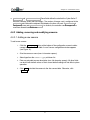
4.4.2.1 Adding a new camera
To add a new camera:
1.
Click the New Entry button at the bottom of the configuration screen to add a
camera to the site camera table. A new Camera configuration window appears
(see Figure 10).
2.
Give the camera a name (max. 8 character spaces).
3.
Select type from the Camera type pull-down list.
4.
Enter an extended camera description (max. 48 character spaces). All other fields
can be left with default values as their current default settings will not affect system
operation.
5.
Click Add to include the camera to the site camera table. Otherwise, click
Cancel .
15
Chapter 4 – Connection screen
FIGURE 10. ADDING A NEW CAMERA
4.4.2.2 Camera data modification
Click the Modify button, located at the bottom of the Camera configuration window, to
modify the camera data. The Camera configuration window appears.
4.4.2.3 Removing a camera
Click the Remove button, at the bottom of the screen, to delete a camera and its
associated data.
4.4.3 Defined cameras table
All configured cameras for the selected site are shown in the Defined Cameras table.
Clicking on any row selects the camera listed in that row.
In addition, a camera can be selected with the
left of the Camera configuration window, if desired.
16
position buttons at the bottom-
Chapter 4 – Connection screen
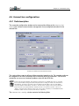
4.5 Connection configuration
4.5.1 Field description
The connection configuration window can be accessed by clicking on the Connection
Config tab. It allows communication management of any configured connection for the
selected site.
FIGURE 11. CONNECTION CONFIGURATION SCREEN
The system allows users to define multiple connection types for a site. For example, a site can
be configured for an ISDN connection and a secondary MODEM connection. The MODEM
connection can serve as a backup if problems arise with the ISDN line.
It can not be stressed enough that, when using the various protocol communication choices, each must
have its own IP address and separate subnet. In CyberView for example, the LAN connection will have
the IP address, 192.168.2.2; the modem connection will have the IP address, 192.168.3.2; the ISDN
connection will have the IP address, 192.168.1.2. In other words, each protocol has its own “IP Circuit
Tunnel” from the CyberStation™ Remote Controller. In the Cyberstation™, “Circuits” context , the
“dialup” or modem circuit could be 192.168.3.2 (Local) 192.168.3.1 (Remote). For the ISDN Circuit the
IP address could be 192.168.1.2 (Local) and 192.168.1.1 (Remote).
The Connection Config window contains the following fields:
17
Chapter 4 – Connection screen
!
!
Phone / NRI —displays the number to dial (14155551212) in ISDN or MODEM
connections. This field will be ignored if a LAN connection is selected.
IP Address —sets the IP address for the connection. It is always needed.
!
Connection Type —selects the connection type. Allowed connection types are: LAN,
ISDN, X25(Custom/Optional), MODEM and F.RELAY (Custom/Optional).
!
Connection Device —displays the device selected for the connection. Available
devices will be automatically detected by the application from the available communication
choices programmed in the PC, located at the bottom of the window. If the device has been
programmed in you PC, it will be an available choice. Care must be taken when choosing
the proper corresponding transmission device for the communication protocol used.
!
Callback Connection —uses ISDN specific features, and allows CyberView™ to
request the remote system to originate a call. This is performed by signaling information
only, so no cost is incurred locally. Call costs are incurred by the remote station. The PC
must be configured to accept incoming calls, as is explained in Section 4.5.5 Incoming calls
configuration. This feature is only available on ISDN connections.
!
Connection UDP/TCP —displays the image reception type from the remote systems,
using either UDP or TCP. With UDP, LAN speeds up to 35 ips can be achieved if a single
camera is displayed. In general UDP is used in special LAN applications when real time
speed is required (e.g., digital video in LAN). In WAN environments, UDP does not improve
speed. For the typical CyberStation™ applications in which CyberStation™ is recording from
the cameras and the communications are PSTN, ISDN or corporate WAN networks, it is
best to use TCP. In busy LANs, UDP packets can be lost, resulting in defective images. If
so, select TCP.
!
Multilink —allows two connection links in the same PPP logical circuit, doubling its
data transmission rate (usually at twice the cost, since two calls are set). This parameter is
only valid for Windows® 2000 and XP.
If the application is running under Windows® 95, 98, or Me, multilink PPP must be set in the host
system’s Dial-Up Networking tool, where CyberView™ is installed (see Section 4.5.4.1
Multilink configuration).
18
Chapter 4 – Connection screen
4.5.2 Adding, removing and modifying connections
4.5.2.1 Adding a new connection
To add a new connection:
1.
Click the New Entry button at the bottom of the configuration screen to add a
new connection for the selected site. The Connection Settings window
appears.
2.
Select the Connection type .
3.
Enter the remote CyberStation™ system’s selected protocol unique IP
address .(see Note on page 17).
4.
If MODEM or ISDN connection is selected, enter the Dial number (phone
number) to dial and then choose the appropriate MODEM or ISDN connection
device from the device table.
5.
When choosing the proper device, note that the column Type must match the field
Connection type . Other fields can be left with their default values.
6.
Click Accept to add the connection to the available choices for the site.
Otherwise, click Cancel .
19
Chapter 4 – Connection screen
7.
FIGURE 12. ADDING A NEW CONNECTI ON
4.5.2.2 Connection data modification
Click the Modify button at the bottom of the configuration screen to modify the selected
connection data. The New Connection Settings window appears. To modify the
Connection type , the connection must be removed and a new one created.
If LAN connection type is selected, Callback connection and Device type
selection fields will be disabled.
4.5.2.3 Removing a connection
Click the Remove button at the bottom of the connection screen after selecting the connection
from the list to remove the selection choice from the system database.
20
Chapter 4 – Connection screen
4.5.3 Connection selection table
All available connection devices for the selected site are displayed in this table. This table
reflects all communication devices currently installed in the computer. Highlight and click on a
row to select a connection device. If a communication device is required for CyberStation™
communication, it must first be added through Windows’s control panel before it is displayed in
CyberView’s Connection Selection Table.
4.5.4 Outgoing calls configuration
Outgoing calls are calls which originate from the PC. These calls occur when the user connects
to CyberStation™, using the CyberView™ application to view real time images or download
sequences from the hard drive. In this case CyberView™ uses Windows’s Dial-Up
Networking to make dial up calls (ISDN, PSTN, and GSM calls). Dial-Up Networking must be
installed and available in the same system if dial up calls must be performed. CyberView™
creates a new Dial-Up Networking entry to for each ISDN or MODEM connection added.
4.5.4.1 Multilink configuration
The Multilink configuration feature allows two connection links to be used in the same PPP
logical circuit, doubling its data transmission rate (usually at twice the cost, since two calls are
set).
Follow these steps to configure a multilink connection when the application is running over a
Windows® 95 or 98 system.
1.
Create an ISDN connection for the site and make a call. A new entry is created in
PC Dial-Up Networking.
2.
Double-click on My PC and open Dial-up Networking.
3.
Open the properties window of the PC Dial-up connection icon with the same
name as the site with the connection to be modified (click with the mouse right
button).
4.
Click on the Multilink tab.
5.
Click Add .
6.
Select the desired device. Select channel 1 if ISDN connection was using channel
0, or select channel 0 if it was using channel 1.
7.
Provide the new channel the same number to dial as used in the connection.
21
Chapter 4 – Connection screen
With Windows® 2000 and XP, multilink calls are automatically configured from CyberView™
(see Section 4.5.1 Field description).
4.5.5 Incoming calls configuration
This procedure applies to incoming calls to the CyberView™ host PC, which originate from the
CyberStation™ remote system due to Alarms being set or Callback calls. In this case
CyberView™ uses Microsoft’s Remote access server for incoming call reception from
CyberStation™ in the PC.
This configuration procedure applies for Windows® 95 and 98. For Windows® NT and Windows®
XP see Appendix 1.
Due to operating system issues, incoming calls are not possible with Windows® 2000. We recommend connecting
the system to a LAN with a router to manage the calls to solve this problem.
To configure your PC to enable incoming calls when using Windows ® 95 or 98:
1.
Install the Dial-Up Networking Server, by navigating to: Control Panel ? Add
or remove programs ? Windows installation ? Communications ?
Details.
2.
Select the " the Dial-Up Networking Server in the list shown.
3.
Configure the TCP/IP properties for the Server, by navigating to Control Panel
? Network ? Configuration:
a.
Select “TCP/IP->Dial-up Networking adapter” and click the
Properties button.
b.
In the IP Address tab, select the Specify an IP address radio button.
c.
Type the IP address used in the remote IP field in the CyberStation™
system configuration (see CyberStation™ Reference Guide), and the
Network Mask (usually 255.255.255.0).
22
Chapter 4 – Connection screen
4.
Navigate to the Dial-Up Networking Server configuration:
5.
Dial-Up Networking ? Connections ? Dial-Up Networking Server
6.
Select the adequate device tab, select the channel not used for outgoing calls
when using ISDN.
7.
Select the Allow access radio button.
8.
Click the Change password button.
9.
Enter the same password as entered in the local username field in the circuit
defined in the CyberStation™ system (this is explained in the CyberStation™
Remote Station Reference Guide).
10. Click the
Server Type
button.
11. Select the PPP radio button, and deactivate software compression and encrypted
password.
12. Click Apply .
If the configuration is successful, the State field displays the message “Checking”.
Microsoft ® has assigned a fixed IP address (192.168.55.1) to the “Remote Access Server” in Windows® Me. This
IP address is used when CyberView™ receives incoming PPP calls. This causes some limitations:
!
The ISDN circuit configured in CyberStation™ which was the same for incoming (PC#CyberStation™)
and outgoing calls (CyberStation™#PC), must be split between two different circuits: one for incoming
calls and another for the outgoing calls.
!
If CyberStation™ has to call CyberView™ to send an alarm, and the application does not receive the
alarm after the configured number of retries (because the PC is turned off or other reasons), this alarm
will not be transmitted again until another alarm occurs and the calling process is repeated. If the PC has
another operating system installed besides Me, the expired pending alarms are automatically transmitted
when the user connects to CyberStation™ through the application.
23
Chapter 4 – Connection screen
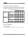
4.5.6 Limitations according to operating system
In conclusion, there are no limitations when connecting to CyberStation™ for video surveillance
through ISDN and when calls originate from the CyberView™ user. Limitations are apparent
when CyberView™ is used to receive alarms. The following table summarizes these situations:
Table 1: Operating System Limitations
PC calls to
CyberStation™
CyberStation™
calls to PC
W95/98
NT
2000
Me
XP
ISDN calls with 1 B
channel
(64Kbps)
Yes
Yes
Yes
Yes
Yes
ISDN calls with 2 B
channels (128Kbps)
Yes1
No
Yes
Yes1
Yes2
IP addresses problems
No
No
No
No
No
ISDN calls with 1 B
channel
(64Kbps)
Yes
Yes
No
Yes
Yes
ISDN calls with 2 B
channels (128Kbps)
No
No
No
No
No
IP addresses problems
No
No
--
Yes
No
1
To communicate using 2B ISDN Channels, the user must manually configure Microsoft DUN.
2
B calls will be automatically configured from CyberView™.
4.6 Users management
4.6.1 Field description
To access the CyberView™ Users Management screen, click the Users Management tab.
24
Chapter 4 – Connection screen
FIGURE 13. USER ’S MANAGEMENT SCREEN
The following fields are displayed in the Users Management screen:
!
USERNAME and PASSWORD —verifies user access to CyberView™ application.
!
Security Profile —displays the user’s security profile, and allows or denies user
access to available system resources based on the profile (see Section 4.7 Security in this
manual). By default, CyberView™ has two security profiles: Security Profile 0 enables
access to all resources, Security Profile 1 denies them.
!
Access level —displays which options are available. (see Section 4.7 Security).
Access Level 9 is the highest level and enables access to all application screens.
25
Chapter 4 – Connection screen
4.6.2 Adding, removing and modifying users
4.6.2.1 Adding a new user
Click the New Entry button, located at the bottom of the configuration screen, to add a new
user. The Users configuration window appears.
Figure 14. Adding a new user
Assign a unique UserName and a UserPassword . Then, assign a Security
Profile and a Screen access level .
The user’s digital image can be stored in the database. Digital images can be saved in the,
c:\Program Files\DC Security
Products\CyberView\InstantDB\televdb\ImagenesUsr folder (if installation default
folder has not been changed). The image must be saved in JPEG format, and its size must be
higher than 350x290 pixels.
To access the image in CyberView™ , click the Select button, located to the right of the
Image file field, and select the user image. Click the Add button to add the new user to
the system database. Otherwise, click Cancel .
26
Chapter 4 – Connection screen
4.6.2.2 User data modification
After selecting a user card to modify, click Modify on the configuration screen. The Users
configuration window appears.
4.6.2.3 Removing a user
After selecting a user card, click Remove at the bottom of the configuration screen to delete it
and all its associated data.
4.6.3 Registered Users table
This table shows all available users. Highlight a row to select its corresponding user.
4.7 Security
4.7.1 Field description
Click on the Security tab to access the Security window, as shown in Figure 15. This feature
allows system security management.
27
Chapter 4 – Connection screen
FIGURE 15. SECURITY SCREEN
The screen is divided into the Access Levels panel and the Profile Panel.
4.7.2 Access level table
All the various CyberView™ applications (Viewer, Sequence, Sites, etc) screens have an
associated access level. For a user to have access to an application screen, his/her access
level must be the same as or higher than the screen access level. For example, a screen with
an access of level 9 (the highest) can only be accessed by users with access level 9.
The application administrator can modify the access level for any of the available screens as
needed.
Selecting any of the rows in the table will make the users with access to the selected screen to
be listed in the Users with the selected access level table, located on the bottomleft of the screen.
28
Chapter 4 – Connection screen
4.7.3 Profiles
Profiles are a list of system resources that can be filtered for each user. As an example, if a user
has NO selected in Outputs Access on his/her profile, and attempts to activate or
deactivate any of the outputs, CyberView™ ignores the orders.
CyberView™ can hold up to 10 profiles (0-9). Two profiles are defined by default: Security
Profile 0, which enables access to all resources, and Security Profile 1, which denies access to
all resources.
To define a new profile or modify an old one, use the
buttons, located at the
bottom-left of the Profile panel and to set the profile to be modified and set availability of each
resource. Then, click the Save Profile button, located at the bottom-right of the Profile
panel.
29
Chapter 5
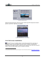
Viewer screen
The Viewer screen displays the real time images from cameras connected to CyberStation™
remote Controllers. Connection to CyberStation™ remote systems must be made before
accessing the Viewer screen.
FIGURE 16. VIEWER SCREEN
30
Chapter 5 – Viewer screen
5.1 Screen layout
CyberStation™ remote site input and output signal status states are monitored to the right of the
screen. Four camera displaying QQCIF formatted images can be seen as small displays to the
right of the main display, which is CIF-sized. Below the small displays are the system-configured
camera icons. Below the system configured camera icons are two small views used to display
image snapshots. The main image screen is located to the left, above the control buttons used
to control the camera and recording process.
5.2 Inputs / outputs
This option displays information on the input and output status states, and allows the user to
take action. If one of the inputs connected to a sensor is activated, the circle to the left of the
input will turn light green. Outputs can be activated or deactivated by clicking on the
corresponding box to the left. When activated, the box appears as checked.
At the pull-down menu, the user can select Inputs Legend for a review of the
input LED colors and what they represent as shown here.
5.3 Small displays
Real time images taken from each of the CyberStation™ associated cameras are displayed in
QQCIF size. Each display the associated camera’s name, and is shown in the box above it. The
two buttons below each display allows users to stop or play the image. Only cameras configured
using the Cameras Config tab, are displayed.
CyberView™ automatically assigns a camera to each display. The user can also assign a
camera to each display. All available camera icons are located between the small displays and
the Captured images panel. Assigning a new camera to one of the smaller displays is
performed by first clicking on the camera icon. Then, drag and drop the icon in the small display.
The four cameras can now be watched at any time. Additionally, if user clicks a camera icon,
images appear on the main display.
All displays show real time video by default. Image updates can be stopped when needed by
clicking the Stop
button. Bandwidth can be released in this way for the other displays to
button again, restarts image streaming.
use. Clicking the Play
Clicking on any of the small displays will direct that image to be shown in the main display while,
in the meantime, the small screen will be blanked until returned by clicking on the main screen.
31
Chapter 5 – Viewer screen
NOT RECORDING
RECORDING
FIGURE 17. RECORDING STATUS DISPLAYS
Over each small display, the camera name appears. If a camera has not been configured, the
default names camera1, camera2 and so on, appear. When a camera recorder is active (due to
alarm, post-alarm or continuous recording), the camera’s name changes color, from a light color
to red, notifying the user of the recorder’s activation.
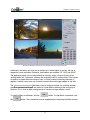
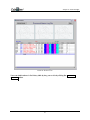
5.4 NxM Matrix control window
The NxM Matrix control window allows users to simultaneously view all cameras configured to
the CyberStation™, as shown in Figure 18.
Click the
button, located to the right of the control buttons row to activate full screen
visualization. CyberView™ supports several camera display formats: 1x1(single, full-screen
image), 2x2, 3x2, 3x3, 4x3, 4x4 and 5x4.
32
Chapter 5 – Viewer screen
FIGURE 18. MATRIX CONTROL PANEL WITH VIEWER WINDOW IN THE
BACKGROUND
Additionally, the table’s cell sizes can be configured. If default option is chosen, cell size is
adapted to screen resolution. Otherwise, three options are available: CIF, QCIF and QQCIF.
The application allows users to automatically or manually assign, cameras to each of the
viewing table’s cell. If automatic, cameras are assigned to cells by camera order. If the number
of cameras is greater than the number of cells, a round (a camera switching sequence) is
applied. If manual, users have only to click the camera icon and images appear on the cells.
The Round time (sec) field allows users to configure the time (for switching between
groups of cameras) that images are shown on screen before switching to the next group of
cameras. This is used to allow viewing groups of cameras on larger display screens
To start the Matrix visualization, click the
the
button. To stop Matrix visualization, click
button. The visualization must be stopped before configuring the Matrix window.
33
Chapter 5 – Viewer screen
The NxM Matrix control window can be minimized to view all images. To reestablish its normal
size press the Esc key. To exit the Matrix window, click the open door icon at the top-right
corner.
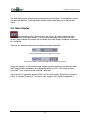
5.5 Main display
The main display in the Viewer window (see Figure 16), shows images from the
selected camera in the small displays. Users can drag and drop camera icons to the Main
Screen. When selected, the camera icon visualized in the main display will appear surrounded
by a red border.
There are two indicators above the main display providing image data:
The indicator above shows image size in bytes.
This above indicator shows the image rate in images per second.
Image size depends on the selected image compression and resolution, and upon the image
itself. Image update rate depends on available bandwidth, the PC’s CPU power on which
CyberView™ runs, and the remote controller’s data load.
The CyberView™ application accepts NTSC and PAL video formats. By default, the format is
NTSC. To configure CyberView™ to receive video images in PAL format see Appendix 1.
34
Chapter 5 – Viewer screen
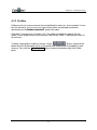
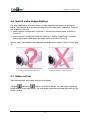
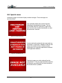
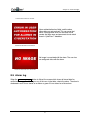
5.6 Special video image displays
The video displayed on the viewer screen is usually video from the cameras in the remote
station. They correspond to the cameras configured in the CyberView™ application. There are
two exceptions to this rule:
!
when a camera is configured in CyberView™ and not in the remote station as shown in
FIGURE 19.
!
when a camera is configured in both the CyberView™ and the CyberStation™ controller,
and no video signal is detected in the remote station as shown in FIGURE 20.
In these cases, the exceptions are highlighted and displayed as shown in Figure 21 and Figure
22:
FIGURE 21. CAMERA NOT CONFIGURED
FIGURE 22. CAMERA WITH NO VIDEO SIGNAL
5.7 Video control
Video control buttons are located below the main display.
and the Play
.buttons are located to the left. The stop button discontinues
The Stop
image updates for the main display. The main display shows the last image taken until the Play
button is clicked.
35
Chapter 5 – Viewer screen
5.8 Recording
Users can record video shown in the main display and save it to the PC hard drive.
button is located to the right of the Play button. When the Record button is
The Record
clicked, the system begins recording until the user clicks Stop or the hard drive is full. The video
recording is stored with the site name, and date and time to better locate it when necessary.
The recording is stored in the same folder as the sequences, which are copied from the remote
site hard drive, making the recorded video accessible from the Sequences screen (see Section
6.6 Hard drive sequence management).
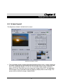
5.9 Image adjustments
When image characteristics need to be modified, using the
button Image
properties can be adjusted to improve user visualization. The button is only enabled when a
camera is displayed on the main display. If no camera is displayed in the main display, the
button is lighten/blurred, indicating that it is currently disabled.
FIGURE 23. IMAGE SETTINGS
When a camera is displayed in the main display screen, click the
button and
three sliding bars (shown in Figure 23) will appear below the button. These sliding bars are:
Bright, Color and Contrast. When the brightness, color and contrast properties are
modified, the changes are applied to the remote site hardware image compressor, not to the
camera. In this way, it is sometimes possible to correct changes in the camera’s working
environment. To return the settings to their default values, click the Default values button
(middle button at the top-right of the main display). Click the Save camera adjustment button
(top button at the top-right of the main display) to save the new settings and values.
36
Chapter 5 – Viewer screen
In addition, when clicking the
display will also appear:
button, three buttons at the top-right of the main
Save camera adjustments
Return the parameters to their default
values
Adjust image quality
The fourth button,
main display.
, is used for image resolution, and is located at the bottom-right of the
Below the
button (lower button from the three at the top-right of the main display) allows
modification of the image compression setting for the camera in real time, therefore modifying
and improving their ‘quality’. A vertical sliding bar appears when the Image quality
clicked, showing this image,
, with a
sign at the top and a
button is
sign at the bottom of
sign increases image quality. This button
the sliding bar. By moving the glide towards the
does not work if the remote system is configured with fix size images (see Reference Manual,
configuration command image-size in the video context).
The
button selects image resolution sent by the remote site and shown in the main display.
Default resolution is CIF. Default resolution changes to QCIF when the
button is clicked.
The QCIF image is smaller, and only the top-left quadrant of the main visor is filled. Because its
size is smaller, less bandwidth is needed and a higher update rate is possible (more images per
second).
The
and
buttons control the Iris and Focus, which allows control of these
parameters if the camera supports them.
37
Chapter 5 – Viewer screen
5.10 VISCA Camera control and auto tracking feature
This unique control capability is only enabled if the selected camera has been defined as
moving Sony (see 4.4 Camera configuration). These buttons control auto target tracking and
back light control for cameras that support the VISCA protocol. To learn more on this feature,
consult an official Sony dealer.
To configure the auto target tracking feature, configure the camera as a Sony Moving Camera.
Click the Target selection button (Figure 24) to select the object for the camera to follow, then
click the Start button. For further details, consult the camera’s user manual.
FIGURE 24. CAMERA CONTROL BUTTON S
5.11 Remote camera control
Some cameras can be controlled remotely with CyberView™ . Control capacity depends on the
camera features. The specific camera type should be known when configured on the
CyberStation™. Usually, only orientation and zoom are controlled.
The camera control icon (see Figure 25) is located below the main display. Clicking the icon
moves the camera (and the image) in the direction of the arrow in the control icon. Clicking the
+ and – buttons activate the zoom feature, so that users can move in on or away from
visualized objects.
FIGURE 25. CAMERA CONTROL ICON
Remember, depending on the connection type, camera control message transmission and
processing can take variable amounts of time. It may be useful to change the main display
resolution to QCIF when connected at low speed (PSTN) to follow camera movements.
38
Chapter 5 – Viewer screen
A good knowledge of the camera control operation is recommended for its adequate use. When
the camera control icon is clicked to move the camera, a command is sent to the remote site for
the camera to move. When the mouse button is released, a command is sent for the camera to
stop moving. If the camera control icon is clicked repeatedly, the camera will only move slightly.
Hold down the mouse button for a second or two for the camera movement to be clearly and
completely received.
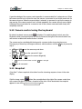
5.12 Camera control using the keyboard
By default, keyboard camera control
is disabled. To enable keyboard control, press the
Keyboard camera movement button. It is the first button to the right of the camera control icon,
and remains enabled until another button is clicked.
The camera can be controlled with the keypad in a manner similar to moving the mouse.
Pressing any of these keys will begin movement, which continues until the 5 key is pressed to
stop it:
!
8/↑ and 2/↓ move the camera up and down
!
4/← and 6/→ move the camera left / right
!
1 , 3 , 7 and 9 moves the camera diagonally
o
!
1 moves the camera down and left, 3 down and right
5 stops all movement.
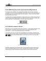
5.13 Snapshot
CyberView™ allows snapshots to be taken from the streaming sequence shown in the main
display.
Click the image capture
button (the second button to the right of the camera control icon,
with a camera image in it) to take a snapshot of the video. When deselected, the snapshot
appears in one of the Captured images panels.
39
Chapter 5 – Viewer screen
FIGURE 26. CAPTURING IMAGES
When the image in this panel is clicked, the image (stored using JPEG compression format) is
opened, using XnView 1 application, for modified.
FIGURE 27. A CAPUURED IMAGE SHOW N IN XN VIEW
5.14 Full screen visualization
Click the Full screen visualization button, located at the top-right of the main display, to
change the stream in the main display to full screen mode. The video is a mathematical
interpolation of the images received. Its quality may seem lower than the video seen in the main
display. Click on the video image to return to standard visualization.
1
Freely distributed software handed over by Pierre Gougelet. To learn more about this software, visit http://www.xnview.com/.
40
Chapter 6
Sequences screen
6.1 Screen layout
This Sequences window is divided into four zones:
FIGURE 28. SEQUENCES SCREEN
!
The visualization display, located at the top-left quadrant of the screen, is where sequences
are shown. Sequences can be selected from the local hard drive or from a remote site hard
drive. The visualization display is in CIF size. The recorded images can be viewed at a
higher (DCIF) size. When the sizes of the sequence’s images are on DCIF, the application
fits the images in the visualization display by applying a display factor to each image. This
process does not affect the images’ original format.
41
Chapter 5 – Sequences screen
!
Video controls are at the bottom-left quadrant. They enable sequence visualization to be
controlled in a similar way as a video player with some added features are explained in
Section 6.5 Visualization control.
!
A calendar is located at the top-right quadrant, with date and time controls to enable quick
sequence access. On the top of the calendar, an LED (HD) informs the user of the remote
station’s hard drive status. If the LED is green, the hard drive has been detected. If the LED
is red, the hard drive has not been detected.
!
Locate at the bottom-right quadrant is a 2x2 grid, where snapshots taken from the
sequences are shown.
6.2 Sequence access
This section centers on accessing sequences from a remote controller. The top right quadrant
allows sequences to be quickly and easily selected and accessed. Its components are
described in
Section6.3 Sequence Sampling.
6.2.1 Calendar
The Calendar screen is used for date selection. If a new date must be selected and the calendar
is not displayed, users can access the calendar by clicking the Calendar radio button. The
radio button is located between the Date field and Calendar label.
The one-month calendar displays day numbers in black, meaning sequences were stored for
that day. White or light-colored day numbers mean no sequences were stored for that day, and
are not selectable. The first days of the next month and the last days from the previous month
are also shown to fill all weeks. If sequences were stored for those days, the days are displayed
in grey.
The displayed month and its year can be selected from the pull-down menus above the
calendar grid. Day numbers are automatically updated when either the month or the year is
changed.
The ! button, located above the calendar and to the right of the year pull-down menu,
changes the calendar to the current month and year.
6.2.2 Timetable selection screen
A selected date is located at the top of this timetable selection screen. The Calendar button
returns the screen back to the calendar.
42
Chapter 5 – Sequences screen
Once a day has been selected, an hour timetable can be seen below the date box with the
hours shown at the bottom and name labels for the cameras to the left. Rows started by each of
the name labels show that a sequence is either stored with that time stamp (squares filled with
the label color) or not (white squares). Red squares indicate that an event was recorded with
that camera at that time.
FIGURE 29. CHOOSING AN HOUR
The Sampling button at the top of the timetable selection screen allows the selection of
several sequences or a long sequence and set the time between images so that a specific
sequence or event can be searched for.
6.2.3 Minutes timetable
When an hour box has been selected, (color-filled squares) another timetable appears in the
same box. The timetable displays a detailed distribution of the selected hour for all of the
cameras while using the same color code. The timetable has a division every ten minutes and
includes ten minutes before and after the selected hour. In this timetable, any minute of the
recorded sequence can be approximately selected to be viewed.
43
Chapter 5 – Sequences screen
The bottom $ located below allows users to return to the hour timetable.
FIGURE 30. CHOOSING AN 10 MINUTE SEGMENT
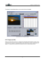
6.2.4 Sequence table
When any minute of the sequence is selected in the timetable, both timetables and the camera
selection menus disappear. A sequence table for the selected hour and four small displays will
appear. The sequence associated with the selected minute is automatically selected.
44
Chapter 5 – Sequences screen
FIGURE 31. CHOOSING A SEQUENCE
Four buttons are located to the right of the sequence selection table.
The topmost button returns the timetable selection screen to the hour and minute
timetables. The remaining three buttons are covered in the upcoming sections.
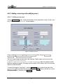
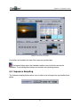
6.3 Sequence Sampling
The sequence sampling feature allows users to collect a set of images from a pre-defined time
period.
45
Chapter 5 – Sequences screen
The Sampling button, located above the hour timetable selection screen (when the minute
timetable selection screen is displayed, the button is not shown), opens the sampling window
(see Figure 32). A sampling period of time can be selected by using the Start time and
End time pull-down menus. The selected cameras that will provide the sequences are
chosen in the Camera check " box panel. Configure the time period in the Continuous
Recording panel to continuously record sequences at intervals. If the setting is set to 00:00,
continuous sequences will not be recorded. The Event mode Recording section is used
for event recorded sequences. If the box is checked " the sampling takes one image from the
pre-event recorded images, one image from the alarm event recorded images, and another
image post-event for each recorded sequence on the sampling event.
Figure 32. Sampling window
The sampling sequence can be configured to use either the continuous recorded sequences
(Continuous Recording parameter left at 00:00) and the selected event recorded
sequences (Event mode Recording box not checked), or both.
It is important to remember that video transmission of images using dialup modems are at speeds of 1 to 2 images
per second, which can take a long time to transmit images. We recommend that users utilize the CyberView™
Sampling Sequence when interrogating the hard drive using the dialup circuit. Utilizing this feature allows users
to download select images at a speed that is more time-efficient. Instead of downloading a 30 second sequence
video clip of about 1 mb in size (which could take 8 to 12 minutes to download in dialup), users can chose a time
period and select a limited number of specific images at set intervals or by specific events. This effort will reduce
the overall size of the download, thereby providing video images transmitted in a relative short period of time.
46
Chapter 5 – Sequences screen
6.4 Sequence selection by content
Four buttons are located to the right of the sequence table (adjacent to Figure 31). The topmost
button is explained in Section 6.2.4 Sequence table.
6.4.1 Visualizing sequences
The second button visualizes selected sequences in the same order as they are
downloaded. The sequences appear in the four small displays, located at the bottom of the
timetable selection screen. To make a sequence selection, hold the Shift and Ctrl keys
while clicking on the sequence rows.
Each small display has an associated button to control the stop/play action, and a box which
displays the start time of the recorded sequence.
Users can also play a sequence on the main display (to the left) by clicking on its small display.
6.4.2 Sequence selection
The third button (lower middle) downloads and visualizes the selected sequence in the
large display. Sequence images are displayed as soon as they are received.
6.4.3 Sequence joining
The lower button joins all selected sequences into one sequence, and is visualized in the
large display.
6.5 Visualization control
Visualization control buttons are located at the bottom-left timetable selection of the screen.
Their function is similar to those of any video playing application.
Three boxes below the main display (see Figure 31) show information about when the selected
sequence was recorded: Date , sequence Start time and Image Time .
Below the boxes, a sliding bar displays the time progression relative to the sequence period
being played at all times.
47
Chapter 5 – Sequences screen
When a recorded event sequence is visualized, the sliding bar appears orange, red or yellow
The color coding depicts whether the images are pre-event, event or post-event recorded. An
“Alarm” message appears when the images are from the event period.
A new button
appears to visualize and identify the exact moment the alarm event has
taken place (e.g., when the window was broken or the door is breeched).
FIGURE 33. VIEWING CONTROL BUTTONS AND ICONS IN THE
BOTTOM-LEFT QUADRANT OF THE SEQUENCE
SCREEN
Video control buttons are similar to those found in most video viewing applications. From left to
right respectively: Fast rewind, Previous image, Play backward, Stop, Play forward, Next image
and Fast forward (as shown in Figure 31).
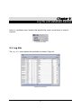
6.6 Hard drive sequence management
Click the Hard drive sequence management button to open the Sequence
management window (Figure 34). To the left of the window is a list of all sequences previously
stored on the hard drive of the PC containing CyberView™. When a sequence is selected its
number of frames is shown in the Frames box at the bottom left corner. If it is an event mode
recorded sequence, the Alarm field displays the message OK. The Date box displays the
date recorded.
48
Chapter 5 – Sequences screen
Figure 34. Sequence management window
Clicking the Visualize sequence button displays the selected sequence.
To save the visualized sequence to the hard drive, type a name for the
sequence in the Sequence name field, located above of the sequence
table. Then, click the Write sequence button.
Selecting a sequence and clicking the Convert Sequence into
QuickTime Video button, converts the sequence to QuickTime Video
format.. Converted sequences are saved in the following directory:
c:\DC Security Products\CyberView\telev2\quicktime
Removes the selected sequence.
49
Chapter 5 – Sequences screen
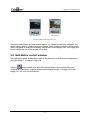
6.7 Taking and editing snapshots
The Capture image button takes a snapshot of an image in the selected sequence.
Snapshots are displayed in the Captured images grid at the bottom-center of the screen. When
clicking on previews in the grid, XnView will launch for snapshot modification. Snapshot images
are saved in:
c:\Program Files\DC Security Products\CyberView\tele2, by default, for viewing.
The Signed image button takes a signed snapshot of a selected image in the viewed
sequence. Signed snapshots are images incorporated with a digital signature providing
verification that the signed imaged has not been modified in any way. The signed snapshots are
displayed in the Captured images grid at the bottom-center of the screen. When clicking on
previews in the grid, XnView will launch the signed image for review. Digital signed images are
saved, by default, in the image user folder:
c:\Program Files\DC Security Products\CyberView\InstantDB\televdb\ImagenesUsr
FIGURE 35.CAPTURED OR SIGNED IMAGE
50
Chapter 7
Control panel
This screen is not used in this version of CyberView™ software.
51
Chapter 8
Alarm manager
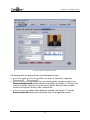
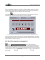
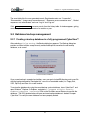
8.1 Alarm reception
CyberView™ includes alarm reception application to support I/O alarms from CyberStation™
remote controller. Dial-Up Networking must be correctly configured for this feature to be
available when running on Windows®. Windows ® must be configured to call the system when an
alarm is detected. The alarm message can be handled and registered only if CyberView™ is
running.
Figure 36. Receiving alarms
52
Chapter 8 – Alarm manager
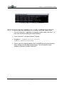
Received alarms are automatically saved in the system database as pending alarms.
CyberStation™ stores alarms when the CyberView™ is off-line. When CyberView™ is on-line,
all pending alarms are automatically retrieved.
When CyberView™ receives a high priority alarm, the Alarm manager window is automatically
opened. The alarm is highlighted and its associated images shown in the display. The user has
the can use set the remote site connection to either verify the alarm or leave the alarm for future
review. If no action is taken within 2 minutes, a warning appears to inform the user that the
remote connection will be cleared.
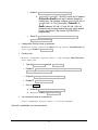
To process alarms, the user must decide whether the alarm is real or not. Click the Alarm or
False Alarm buttons to catalog the alarm, and move it to the alarm log database. To delete
unacknowledged pending alarms, see Section 3.1 Pull down Menu bar.
8.2 Screen layout
The Alarm manager window is divided into five zones (see Figure 36):
!
At the top of the screen is the remote site IP address that generated the alarm, the name of
the site and a button to close the window and return to the application main screen.
!
The second zone shows the images associated with the alarm. If the alarm has no
associated images or an error has occurred, a message is shown in the display, explaining
the cause of the error.
!
The zone below shows detailed information about the detected event. It also shows the
remote site where the alarm originated. The number to the right displays the number of
pending alarms.
!
The table in the lower-center of the window, displays pending alarm information. The
Connect button, located to the right of the table, allows connection to the site where the
alarm was generated. The Alarm or False Alarm buttons classify and store the
selected alarm as true or false.
!
The text box, located at the bottom of the window, allows users to enter any details about
the selected alarm.
8.3 Field description
The remote site IP address of the checked for alarms, is shown at the top-left of the window. Its
name is shown at the top of the site.
Below each display, a field indicates whether the image was taken before the event (Pre-alarm),
just after the event was detected (Alarm), or after the configured event recording period (Postalarm).
53
Chapter 8 – Alarm manager
The event information zone contains following fields:
!
Event — Message set for the alarm title that should describe the cause of the alarm.
!
Priority —Associated to the alarm severity, where 1 is the highest priority (greater
severity), 2 is the medium priority and 3 is the lowest. It must be configured at the remote
site.
!
Client —The CyberStation™ remote system owner.
!
Telephone —Telephone number to use if the client needs to be reached by phone.
!
Country , City and Address —Remote site geographical location.
The pending alarm table contains following fields:
!
!
Site —Name of the remote site that sent the alarm.
Initial time —When the recording was initiated. This panel is divided into three fields:
hour ( ih ), minutes ( im ) and seconds ( is ).
!
Day , Month and Year —Date when the event took place.
!
Event —Descriptive text associated with the event.
!
End Time—Recording end time is divided into three fields: hour ( eh ), minutes (
em ) and seconds ( es ).
Any additional event information can be entered in the Description box to be stored with
the event information.
8.4 Alarm button
When the Alarm button is clicked, located to the right of the window, the selected event
information is stored in the historical database as a real alarm. A window appears prompting the
user to write a description of the alarm being stored.
8.5 False Alarm button
When the False Alarm button is clicked, the selected event information is stored in the
historical database as a false alarm. A window appears prompting the user to write a description
for the alarm being stored.
54
Chapter 8 – Alarm manager
8.6 Remote site connection window
If no connection is made with the remote site within 2 minutes after the alarm has been
received, CyberView™ displays a warning, informing the user that the remote system’s
connection will be closed. If the user accepts the connection, the online remote system
connection is used.
8.7 Connect button
When the Connect button is clicked, CyberView™ connects to the remote site that sent the
alarm. Users can watch the events take place in real time. If the link to the remote site is still
open, the application uses it. Otherwise, a new connection is initiated. If a connection to another
site was opened when the Connect button was clicked, the application will close the active
connection and open a new one to the selected site.
55
Chapter 8 – Alarm manager
8.8 Special cases
Sometimes images in the alarm displays include messages. These messages are
described below.
User verification failed at the remote site when
attempting to download alarm images. This can
occurs either when the CyberView™ login name
does not exist in the remote site database, or when
the password is incorrect.
FIGURE 37. UNAUTHORIZED USER
A name sent by the remote site does not match any
site names in CyberView™ database. Either the site
name in the remote site has not been correctly
configured or it is incorrectly typed when introduced
in the application database.
Figure 38 Unauthorized site
The alarm images can not be retrieved from the
CyberStation™. This can mean that either mean the
simultaneous connection limit has been reached or
the remote site has a problem.
56
Chapter 8 – Alarm manager
FIGURE 39. CONNECTION FAILURE
Alarm authentication has failed, and the alarm
information was not received. This can mean that
either a configuration error has occurred or that
remote site login name and password do not match
those in CyberView™ database.
FIGURE 40. AUTHENTICATION ERROR
No image is associated with the alarm. The user has
no configured video with the alarm.
FIGURE 41. NO IMAGE WITH THE ALARM
8.9 Alarm log
When the View Log File button is clicked, the screen which shows all stored data for
verified alarms appears. Clicking on any of the rows in the table, selects the alarm. The alarm is
shadowed in red if it was stored as an alarm or green if it was stored as a false alarm.
57
Chapter 8 – Alarm manager
FIGURE 42. ALARM HISTOR Y
Users can delete alarms in the history table by day, year or site by clicking the Selective
Removal button.
58
Chapter 9
Log file and database backup
In the File pull-down menu, located at the top-left of the screen, are two items as shown in
Figure 43.
FIGURE 43. FILE MENU
9.1 Log File
The Log File menu displays the event table, as shown in Figure 44.
FIGURE 44. EVENT TABLE
59
Chapter 9 – Log file and database backup
The event table lists the user-generated events. Registered events are: “Connection”,
“Disconnection”, “Image server connection error”, “Sequence server connection error” , “Socket
sequences not authenticated” and user “Log In” and “Log out”.
Click Selective Remove to remove events from the history table. A window appears, giving
users the option to remove all events of a month or a year.
9.2 Database backup management
9.2.1 Creating a backup database in a fully programmed CyberView™
After selecting File | DB Backup, the Backup dialog box appears. The Backup dialog box
provides a choice to either accept a newly created backup that overwrites the old backup
database, or to cancel.
FIGURE 45. BACKUP WINDOW
Once a new backup is accepted and written, users can go to InstantDB directory and a new file
with the backup designation "backupbd.tar", save it to a recordable media (i.e. Floppy Disk,
CDR, Zip Disk) and store it in a safe location.
To restore the database by using the saved backup system database, close CyberView™ and
open Windows® Explorer. In Explorer, navigate to c:\Program Files\DC Security
Products\CyberView \InstantDB. Click on the file folder named Restore to execute the
database. The DOS window below will open and new backup database is loaded. Re-open
CyberView™ to verify the new database has been properly loaded.
60
Chapter 9 – Log file and database backup
FIGURE 46. DOS WINDOW — DATABASE BACKUP EXECUTION
9.2.2 To load a backup database in a newly installed CyberView™:
1.
Once the CyberView™ application is completely installed, open CyberView™ at
least once time before loading the backup database.
2.
Close CyberView™ and open Windows® Explorer.
3.
Navigate to c:\Program Files\DC Security
Products\CyberView\InstantDB.
4.
Place a copy of the backup database file in InstantDB directory and execute the
file by clicking on the file folder named Restore. This will reload the saved
database in the newly installed CyberView™ .
61
Appendix 1:
Incoming calls configuration
Configuring Windows ® NT to receive calls from CyberStation™ Controller:
1.
Configure the Dial-Up Server:
a.
Navigate to: Control Panel->Network. Select Services tab. Select
Dial-Up Server.
b.
Click
c.
Click To configure... .
d.
In Port use, click the To make and to receive calls radio button.
e.
Click Network .
f.
In Protocols to make calls: select " TCP/IP , disable % the other
protocols.
g.
In Server configuration:
&
Properties , and select the device.
NetBEUI , IPX disable %.
&
Select ' To allow any authentication type, even plane
text.
&
Select " TCP/IP ,and click in
To configure… :
•
Enable ' in To allow remote TCP/IP clients access to:
All the network or Only this system, as you wish.
•
Disable ( Use DHCP for allocating address to remote
TCP/IP clients .
62
•
Enable ' Use the address static group :
♦
•
2.
Begin IP1 to IP2. The WNT use the first IP address
(IP1) as his own and the rest are IP address allowed for
remote users. For example, configure Begin 192.168.1.1
to 192.168.1.10. The CyberStation™ should use IP
address between 192.168.1.11 and 192.168.1.254, not
included in the first range defined but in the same network
(in the CyberStation™ the masque 255.255.255.0 is
programmed).
Select " To allow remote client to ask for an
specific IP address .
Configure the Dial-Up server as automatic:
In Control panel->Services, select Dial-Up Server and double click. In
Start type enable ' Automatic .
3.
Create a user:
In Start->Programs->System tools-> User manager. Select the menu
User->New user
•
Type the User name and the Password .
•
Disable % The user should change the password in the
following start session .
•
Enable " The password never expires .
•
Disable % Account disable .
•
Click on Dial :
♦ Enable " To enable user to call.
♦ In Answer, enable ' Not answer .
4.
You can see the state of connection in:
Start->Programs->System tools a->Dial-Up manager:
If the call is established, you can disconnect it.
63
Configuring Windows ® XP to receive calls from CyberStation™ Controller:
1.
2.
Navigate to: Control panel-> Network connections and Internet->Network
connections.
a.
Select Network task, Create a new connection, and next, click
Next > .
b.
Click ' in To configure an advanced connection , and Next > .
c.
Click ' in To accept incoming connections , click in Next > and
follows the new connection assistant .
In Control panel-> Network connections and Internet-> Network
connections.
a.
Select in Network task, Change the configuration of this connection. In the
tab Network functions, click ' in Internet Protocol (TCP/IP) , and
next, in Properties….
b.
Click ' in Specify TCP/IP address and then:
c.
&
In From , write the start IP address. For ex. 192.168.1.2.
&
In To , write the final IP address. For ex: 192.168.1.3.
Enable " To allow to the system which calls to specify
his own IP address .
64
Appendix 2:
Ports configuration
In the CyberView™ application the default ports are:
!
image server
2000
!
sequence server 2001
!
inputs/outputs
2002
!
alarms
9001
To modify the ports, follow these steps:
1.
Navigate to: Program files->CyberView->telev2
2.
Right-click the puertos.cfg file and select Edit.
3.
The following file appears by default: 2000,2001,2002,9001.
4.
Modify the file as needed. The file format must be the same (port number plus
comma without space). Otherwise, the ports will not be recognized in the
application.
The configured ports in the application are the same for all connected CyberStation™ models.
65
Appendix 3:
Automatic configuration
CyberView™ automatically downloads camera configuration from remote equipment, and stores
the updated information in the application database.
When connecting to a CyberStation™, the system checks for configuration modification at the
remote. If modifications are detected the Configuration update window appears,
prompting the user to accept or deny the local database modification as shown below.
To deactivate this function, click the Options tab, and select Automatic configuration and
deselected the item Show.
CyberView™ renames the site in the database with the one configured in the site-name field in the Alarms
context from the remote equipment. If this name already exists, the site is a default name. If no name is
configured, modifications will not be made to the site’s name on the local database.
If the application detects two cameras with the same name when downloading information, the second
instance is given the default name.
The activation of this functionality applied to all connections.
66