1
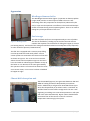
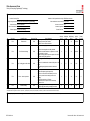
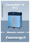
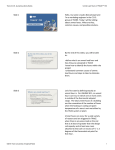
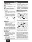
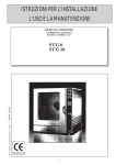
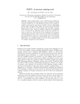
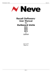
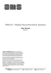
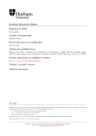
FACULTY OF COMPUTING, ENGINEERING AND SCIENCES
SCHOOL OF ENGINEERING
Standard operating procedure for Biomass boiler
demonstration rig (F12c)
Contents
Scope ....................................................................................................................................................... 1
Apparatus ................................................................................................................................................ 2
Windhager biomass boiler .................................................................................................................. 2
Fuel storage......................................................................................................................................... 2
ClimateWell absorption unit ............................................................................................................... 2
Buffer storage ..................................................................................................................................... 3
Pumps and fan settings ....................................................................................................................... 3
Gate valves, air bleeds, filling loops and expansion vessels ............................................................... 3
Flow meters and thermocouples ........................................................................................................ 3
Operating procedures ............................................................................................................................. 4
Start-up procedure of the boiler (after prolonged non-use) .............................................................. 4
Shut-down for cleaning/maintenance/inspection .............................................................................. 4
Normal operating conditions (temperature or timer controlled) ...................................................... 5
Heating circuits (F12 and F12c) ........................................................................................................... 5
Absorption unit ................................................................................................................................... 5
Data acquisition ...................................................................................................................................... 6
Fuel level ............................................................................................................................................. 6
Boiler ................................................................................................................................................... 6
ClimateWell unit ................................................................................................................................. 6
Temperature and flows....................................................................................................................... 6
Maintenance ........................................................................................................................................... 7
Responsibilities ....................................................................................................................................... 8
Health & Safety (Risk Assessment) ......................................................................................................... 9
Other ..................................................................................................................................................... 10
Scope
This document is aimed at relevant personnel operating the biomass boiler demonstration unit as
part of the ARBOR project. It will give an overview of the different apparatus installed, operating
procedures of various key moments of the unit, maintenance as well as Health & Safety guidelines.
For any additional information please refer to the user manuals (located in the folder next to the
boiler in F12c and/or the ARBOR personnel listed at the end of this document). Any warning sign and
yellow lines should be respected at all times.
Any unauthorised person should stay outside the exclusion zone at all times. This is
indicated by a black and yellow striped tape on the floor. Do not touch any surfaces,
pipework and parts of the chimney!
Annexe 1 – Fuel price review
Annexe 2 – Boiler efficiency overview (outstanding)
Annexe 3 – Risk Assessments
1|Page
Apparatus
Windhager biomass boiler
The Windhager biomass boiler (Figure 1) operates on biomass pellets
(virgin wood) and has a rated output of 45kW. The unit is selfcontrolling and a daily inspection for faults/issues (indicated by the
unit) or upon visual inspection are sufficient. The unit should be kept
closed at all times during normal operating hours. There is no need to
change any of the parameters of the unit.
Fuel storage
The fuel silo (black tank) can store approximately 3.5 tons of pellets.
The silo can be filled by a sliding trap in the lid of the tank. Please
Figure 1 - Windhager boiler
consider the separate risk assessment for filling the hopper (2-3 times
per heating season). Fuel levels of the storage should be checked on a weekly basis and (if required)
an order should be placed (cf. Maintenance).
The fuel silo is equipped with a vacuum pump filling
unit that provides the boiler with pellets. Various
suction probes are mounted at the bottom of the tank
as shown on Figure 2. This is set to 6 hour intervals
where the unit will check pellet usage over the last 6
hours and make an educated guess whether to top up
the boiler or not. Because of the noise generated by
this operation there is a function that allows this to be
set at certain times, in our case it has been scheduled
to happen at night.
Figure 2 - Suction probes
ClimateWell absorption unit
The ClimateWell (Figure 3) unit generates between 7kW and
10kW of cooling that will be dissipated by an air blown
cooler. Additionally it will generate 20-30 kW of heat (up to
40°C) also dissipated by an air blown cooler. It will draw 1520 kW of heat from the buffer storage tank. The unit is selfregulating. According to its internal temperatures it will open
and close valves automatically. Bypass valves should allow a
continuous flow of the various circuits for real-time
temperature monitoring by the system.
Figure 3 - ClimateWell
2|Page
Buffer storage
The buffer tank stores 825 litres of water. The heating circuits will be directly fed by this buffer tank
and the ClimateWell unit will draw its heat through a flat plate heat exchanger. The buffer tank is
well insulated and the thermal loss is 3.5 kWh / 24hrs (tested and verified).
Pumps and fan settings
There is no need to regulate any of the pump settings. All pumps are activated according to the
operating conditions of the boiler and/or absorption unit. All loops are equipped with bypass valves
and some of the pumps are self-adjusting to keep a constant pressure in the loop.
The fan(s) can be set to either continuous mode or temperature controlled mode where the set
temperature can be changed according to the desired load on the absorption unit (heat sink and
refrigeration cycle).
Gate valves, air bleeds, filling loops and expansion vessels
There is no need to adjust any of the gate valves in the system (except during maintenance).
All air bleeds are fully automatic and any air pockets in the system should automatically rise to the
highest point and be automatically vented.
The filling loops (located by the expansion vessels) should be checked before each heating season or
prolonged non-use of the respective circuit and topped up if necessary (min. 1bar).
The expansion vessels should be part of the yearly maintenance by approved service personnel.
Flow meters and thermocouples
The flow meters can all be read directly from their respective screens. The flow meters installed on
the heat sink and refrigeration loop can display the water temperature and provide a pulsed output
to be read by a computer.
3|Page
Operating procedures
Start-up procedure of the boiler (after prolonged non-use)
-
Check fuel level in silo (Be aware of the potential for a build-up of Carbon Monoxide within
the silo).
- Check water pressures are all above 1 bar
(top up if necessary at the two filling stations
located by the two expansion vessels - Figure 4).
- Check for loose wires or open pipework.
- Turn boiler on via control panel.
- Turn absorption unit on via the wall plug as
well as the pumps on the system and power supply
of the flow meters.
- Monitor all processes as the boiler and
Figure 4 - Expansion vessel
absorption unit sensors should indicate any
potential problems.
- Keep an eye on the pumps and check for any water leaks once the pumps start running.
- Once the boiler is in ‘modulating mode’ the room should be getting warm.
Shut-down for cleaning/maintenance/inspection
-
-
-
The boiler will indicate cleaning (every 1200 hrs of
operating) / maintenance periods.
Follow the on-screen instructions to ‘power-down’
the boiler (in case of prolonged intervention turn the
absorption system off as well).
When indicated on the monitor, open both boiler
cover doors at the front (check for temperatures and
use gloves).
Open all the 3 side panels on the right (Figure 6) and
Figure 5 - Dome shape air intake
use a vacuum cleaner (potentially hot ash).
- Use brush to sweep all visible surfaces (start at the top)
and pay attention to the two temperature probes protruding
from the ceiling (remove all residues).
- In the combustor remove all visible ash deposits and
remove the dome shaped steel part in the bottom of the
combustor (Figure 5).
- Use the plastic tube (on cleaning rack) and insert into the
now visible hole. Attach the hoover. Careful handling is required
as this is the lighting part of the boiler. Replace the dome when
finished.
- Clean the bottom bit of the boiler and check for any
clinker in the screws.
- Close the ash ports on the ash bin by pulling the handle.
Figure 6 - Boiler interior
4|Page
-
Roll out the bin and empty in flame resistant container (Make sure to weigh the ash)
Replace ash bin (make sure to lock all seals and open ash ports) and close all openings. If any
of the seals are not properly closed, the boiler will not fire up (negative pressure required).
Carry out any additional maintenance or servicing if required.
Confirm all interventions are finished on the monitor and follow on-screen instructions
(boiler will check for any open doors/vents before lighting).
Chimney sweeping should be carried out by an approved person on a yearly basis.
N.B. Maintenance of the absorption system does not require the boiler to be turned off
Normal operating conditions (temperature or timer controlled)
-
No intervention is required during the normal operating condition of the boiler. The boiler
can be set either to room temperature or timer control.
Heating circuits (F12 and F12c)
-
The desired room temperature for F12 and F12c can be controlled via the respective
temperature controls as any other conventional household boiler (for ease of use).
Care is to be given not to overheat the rooms and the temperature should be adjusted
according to occupancy levels of the room.
Absorption unit
-
The absorption unit can be set to heating or cooling. The fans can be set to run continuous
or be temperature controlled. (This will use the inlet temperatures to the respective heat
exchangers and can result in the fans operating independently of each other).
5|Page
Data acquisition
Fuel level
The fuel level needs to be monitored on a regular basis. At the back of this folder (annexe 1) there is
a table to record the fuel input into the silo. The electronic version of the file allows for estimating
the remainder of the fuel based on the pellets consumption and on boiler operating time.
Boiler
Fuel usage, temperatures and operating hours can be displayed by the boiler mounted mini-displaydisplay. This data is necessary for the excel logging of the boiler overview and fuel storage level. A
paper version of this can be found in the annexe 2 of this document.
ClimateWell unit
The ClimateWell unit can indicate its current charge status via the display on the unit. Additionally all
temperatures and energy levels can be read by a computer connected via an RS232 cable. Check the
ClimateWell user manual for additional information.
Temperature and flows
The flows are measured with digital flow meters and can indicate flow rates as well as total
accumulated water usage. The two flow meters connected to the heat sink and the cooling circuit
are both able to indicate the flow temperature as well.
6|Page
Maintenance
Ash bin
Combustor cleaning
Heat exchanger (boiler)
Visual
Absorption
Boiler
Chimney
Expansion vessel
When?
Upon request
Upon request
Automatic
Weekly
Issue / modification
Yearly
Yearly
Yearly
What?
Follow instructions
Follow instructions
N/A
For leaks, pressures
Follow instructions
Approved person
Approved person
Approved person
Additional info
User manual
User manual
Self-cleaning
User manual
N/a
N/a
N/a
7|Page
Responsibilities
Dean of Faculty of Computing, Engineering and Sciences:
Professor Hastings McKenzie
-
Ensure that operational procedures are in place for the safe use of the biomass boiler
demonstration rig, including preparation of risk assessments for the facility
Project manager / Faculty Health & Safety advisor / Technical skills specialist
Dr Sacha Oberweis
Barry Cornes
Audra Jones
Graham Preece
-
Ensure that suitable and sufficient risk assessments are in place, along with any necessary
instructions resulting from the finds of the risk assessment
Ensure that safety instructions and operational procedures are complied with for all visitors
Ensure contractors understand and comply with this operating procedure
Ensure the safe operation / maintenance and inspection is carried out as indicated above
8|Page
Health & Safety (Risk Assessment)
There are three separate risk assessments for the boiler system (annexe 3).
-
Standard operating conditions
Fuel loading
Cleaning and maintenance
9|Page
Other
Version
draft
Date
Author
29/05/2013 S Oberweis
Change
n/a
10 | P a g e
Fuel price review
ARBOR project INTERREG IVB
Date
From
Distance Qty
[miles]
CO2 del.
Qp
[kg]
CO2 prod. Cost
[kWh]
[kg]
[kg] [£]
[p/kWh]
24/05/2013 Renuvo
59
1000
4800
-1.9
-10.0 £
-
£
-
29/05/2013 Agripellets
59
80
384
-0.2
-0.8 £
-
£
-
6
2000
9600
-0.4
-20.0 £
Billington
535.00 £
0.06
Risk Assessment Form
Faculty of Computing, Engineering & Technology
To be completed by Risk Assessor:
Location of activity F12c
Member of staff responsible for activity ARBOR team member
Activity being assessed Biomass boiler demonstration rig
Other contributors to assessment Barry Cornes
Assessors name Dr Sacha Oberweis
Assessor contact tel 3565
Date of Assessment 28-May-13
Assessors signature
Review required No
Review Date Due
All completed risk assessments MUST be available to persons undertaking the activity. A copy should also be filed with Claire Booth (Faculty H&S Administrator) if appropriate.
No
Risk Area
Hazard/Process
Object or material at high
temperature - When apparatus is
in use
1
F12c
2
F12c
Electrocution
3
F12c
Fire - Biomass storage
4
F12c
Trip - Trailing pipe work & cables
5
F12c
Fumes - when in operation
6
F12c
Manual handling - when loading
the fuel hopper
Persons at Risk
Control Measures
Staff, Students, 1. Warning notices highlighting potential thermal
Visitors &
hazard from boiler.
Trespassers
2. Restricted access to the unit (yellow zones).
1. All wiring integrated into building infrastructure (no
Staff, Students,
plugs)
Visitors &
2. Warning labels displayed showing location of
Trespassers
emergency isolation panic buttons.
1. All fuels to be properly stored away from sources of
fire.
Staff, Students, 2. Ensure fire extinguisher is readily available.
Visitors &
3. Carbon monoxide detectors in operation to monitor
Trespassers
CO generation in storage.
4. Open venting system to prevent explosion from dust
generation during filling operation
1. Trailing parts/leads to be kept to minimum at all
times.
Staff, Students,
2. Area to be maintained in a clean and tidy state at all
Visitors &
times.
3. All
Trespassers
cabling and pipework attached to walls out of reach.
Severity
(1-10)
Likelihood
(1-10)
Risk Rating
(S x L)
Level of
Risk
Result
(T,A,N,U)
2
4
8
Very Low
A
8
4
32
Medium
A
8
4
32
Medium
A
4
6
24
Low
A
6
3
18
Low
A
6
4
24
Low
A
1. Flue system to be used to direct fumes to the
outside atmosphere (regular inspection).
2. Doors to other areas of the laboratory are to be
Staff, Students,
closed to prevent fumes entering back in to the
Visitors &
building.
Trespassers
3. Constant monitoring of CO alarm.
4. Automatic shut-off system in case of build-up
pressure in flue.
Staff, Students, 1. Use appropriate manual handling procedures.
Visitors &
2. Use appropriate PPE (dust mask) during loading
Trespassers
procedure.
Control measures highlighted in bold indicate recommended improvements needed to reduce the level of risk associated with the hazard
The resultant risk level is graded as follows: T (trivial risk), A (adequately controlled), N (not adequately controlled), U (unable to decide and further information required)
Summary of any key comments to note (general recommendations for improvements, areas of concern, items for review or further action etc)
FCET H&S/3-01a
Document Rev. Date: 15th October 2010
Risk Assessment Form
Faculty of Computing, Engineering & Technology
To be completed by Risk Assessor:
Location of activity F12c
Member of staff responsible for activity ARBOR team member
Activity being assessed Biomass boiler demonstration rig (maintenance)
Other contributors to assessment Barry Cornes
Assessors name Dr Sacha Oberweis
Assessor contact tel 3565
Date of Assessment 05-Jun-13
Assessors signature
Review required Yes (after first maintenance)
Review Date Due
All completed risk assessments MUST be available to persons undertaking the activity. A copy should also be filed with Claire Booth (Faculty H&S Administrator) if appropriate.
No
Risk Area
1
F12c
2
F12c
3
F12c
Hazard/Process
Object or material at high
temperature - When apparatus is
in use
Persons at Risk
Electrocution
Staff
Fire - Biomass storage
4
F12c
Trip - Trailing pipe work & cables
5
F12c
Fumes - when in operation
Staff
Staff
Control Measures
1. Follow on screen instructions (cool-off period)
2. Use high temperature gloves
3. Dispose of potential hot ash in metal bin provided
1. Boiler turns itself down (check for loose wiring)
2. Warning labels displayed showing location of
emergency isolation panic buttons.
3. No loose cables from vaccuum cleaner
Severity
(1-10)
Likelihood
(1-10)
Risk Rating
(S x L)
Level of
Risk
Result
(T,A,N,U)
7
2
14
Low
A
8
4
32
Medium
A
8
4
32
Medium
A
4
6
24
Low
A
6
3
18
Low
A
1. All fuels to be properly stored away from sources of
fire.
2. Ensure fire extinguisher is readily available.
3. Carbon monoxide detectors in operation to monitor
CO generation in storage.
4. Open venting system to prevent explosion from dust
generation during filling operation
5. Boiler will automatically lock down fuel supply inlet
1. Trailing parts/leads to be kept to minimum at all
times.
2. Area to be maintained in a clean and tidy state at all
Staff
times.
3. All cabling and pipework attached to walls out of
reach.
1. Flue system to be used to direct fumes to the
outside atmosphere (regular inspection).
2. Doors to other areas of the laboratory are to be
Staff, Students,
closed to prevent fumes entering back in to the
Visitors &
building.
Trespassers
3. Constant monitoring of CO alarm.
4. Automatic shut-off system in case of build-up
pressure in flue.
Control measures highlighted in bold indicate recommended improvements needed to reduce the level of risk associated with the hazard
The resultant risk level is graded as follows: T (trivial risk), A (adequately controlled), N (not adequately controlled), U (unable to decide and further information required)
Summary of any key comments to note (general recommendations for improvements, areas of concern, items for review or further action etc)
FCET H&S/3-01a
Document Rev. Date: 15th October 2010
Risk Assessment Form
Faculty of Computing, Engineering & Technology
To be completed by Risk Assessor:
Location of activity F12c
Member of staff responsible for activity ARBOR team member
Activity being assessed Biomass boiler demonstration rig (fuel loading)
Other contributors to assessment Barry Cornes
Assessors name Dr Sacha Oberweis
Assessor contact tel 3565
Date of Assessment 05-Jun-13
Assessors signature
Review required Yes (after first loading)
Review Date Due
All completed risk assessments MUST be available to persons undertaking the activity. A copy should also be filed with Claire Booth (Faculty H&S Administrator) if appropriate.
No
Risk Area
Hazard/Process
Persons at Risk
1
F12c
Electrocution
Staff
2
F12c
Fire - Biomass storage
Staff
3
F12c
Trip - Trailing pipe work & cables
Staff
4
F12c
Fumes - when in operation
Staff
5
F12c
Manual handling
Staff
Control Measures
1. Warning labels displayed showing location of
emergency isolation panic buttons.
2. Check for loose wires and cables
1. All fuels to be properly stored away from sources of
fire.
2. Ensure fire extinguisher is readily available.
3. Carbon monoxide detectors in operation to monitor
CO generation in storage.
4. Open venting system to prevent explosion from dust
generation during filling operation
1. Trailing parts/leads to be kept to minimum at all
times.
2. Area to be maintained in a clean and tidy state at all
times.
3. All cabling and pipework attached to walls out of
reach.
1. Flue system to be used to direct fumes to the
outside atmosphere (regular inspection).
2. Doors to other areas of the laboratory are to be
closed to prevent fumes entering back in to the
building.
3. Constant monitoring of CO alarm.
4. Automatic shut-off system in case of build-up
pressure in flue.
1. Always apply safe manual handling procedures
2. Always apply safe working at height procedures
Severity
(1-10)
Likelihood
(1-10)
Risk Rating
(S x L)
Level of
Risk
Result
(T,A,N,U)
8
4
32
Medium
A
8
4
32
Medium
A
4
6
24
Low
A
6
3
18
Low
A
6
3
18
Low
A
Control measures highlighted in bold indicate recommended improvements needed to reduce the level of risk associated with the hazard
The resultant risk level is graded as follows: T (trivial risk), A (adequately controlled), N (not adequately controlled), U (unable to decide and further information required)
Summary of any key comments to note (general recommendations for improvements, areas of concern, items for review or further action etc)
FCET H&S/3-01a
Document Rev. Date: 15th October 2010