1
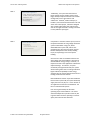
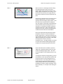
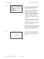
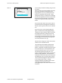
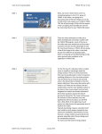
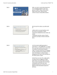
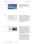
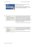
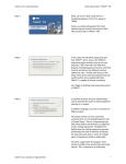
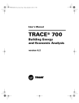
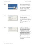
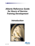
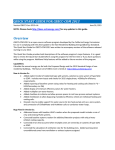
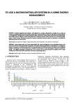
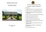
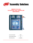
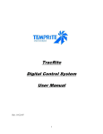
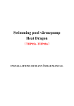
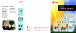
Trane C.D.S. eLearning Series
TRACE 700: Single-Zone VAV Systems
Slide 1 Hello, my name is Audra Benzschawel, and I am a Marketing Engineer in the C.D.S. group at Trane. Today I am going to talk about Single Zone VAV in TRACE 700. TRACE™ 700
Single-zone VAV Systems
Slide 2 We will start with today on what is single zone VAV, basic calculation methodology, how to model it in TRACE, and then finish it off with a classroom example with setting up the system. Learning objectives
•
•
•
•
What is Single Zone VAV (SZVAV)?
Basic calculation methodology
How to model SZVAV in TRACE 700?
Classroom example of SZVAV
Slide 3 Simple Single-Zone VAV System
VFD
Supply airflow modulated based on loads in zone
T
VFD
Controller
Varies cooling/heating capacity to
maintain supply-air temperature at
set point
© 2014 Trane a business of Ingersoll Rand
T
Coils and fan
serve a single zone
All rights reserved.
Single Zone VAV consists of a variable‐volume fan, cooling coil, and heating coil that typically serve a single zone. In this system, a single zone sensor is used to directly vary the supply fan. Like a traditional multiple‐zone VAV system, the cooling capacity is varied to maintain the discharge air temperature. Because only one zone is served, no VAV boxes are needed. Trane C.D.S. eLearning Series
Slide 4 TRACE 700: Single-Zone VAV Systems
Typical SZVAV Applications
• Large, densely occupied zones with
variable cooling loads (Gymnasiums,
auditoriums, etc.)
• K-12 classrooms
• Retail Stores
Slide 5 Potential Benefits of SZVAV
• Potential Benefits
•
•
•
Lower Energy Use
Better Dehumidification at Part Load
Less Fan-Generated noise
© 2014 Trane a business of Ingersoll Rand
All rights reserved.
Traditionally , the system has been found in larger rooftops and air handlers used to serve large, densely occupied zones that have variable cooling loads, such as gymnasiums and auditoriums. However, smaller rooftops, air handlers, and terminal units like blower coils and water‐source heat pumps, have been designed with variable speed supply fans and necessary controls so single zone VAV is starting to be used in many different space types. Compared to a constant‐volume system, some of the potential benefits of using a Single Zone VAV system include lower energy use, better dehumidification at part load, and less fan‐
generated noise. Of course the extent of these benefits will depend on the climate, building layout, and operating hours of the specific building. Since the fan is able to modulate airflow to the space during part‐load conditions, there can be considerable fan energy savings. However, it is important to look at the application to determine expected savings. For instance, if a space consistently has high internal loads, the system will be running more hours in cooling mode with higher airflow and probably see less energy savings than if the system operates more hours in heating mode with lower airflow. Dehumidification is better at part load conditions because even at part load, the system will always supply the same cool, dry air. It is the amount of air supplied to the zone that is modulated. Just like in a traditional VAV system. Less noise is generated by the fan when operating at part load conditions. The actual sound level depends on specifics of the fan, but in general when the fan is operating at a slower speed, the noise level also decreases. Trane C.D.S. eLearning Series
Slide 6 TRACE 700: Single-Zone VAV Systems
variable‐speed fan control
minimum
airflow limit
supply fan airflow
supply‐air temperature setpoint
maximum SAT for heating
design SAT for cooling
design zone heating load
zone sensible load
design zone
cooling load
Slide 7 Modeling SZVAV in TRACE™ 700
Creates Rooms
1. Airflows Tab
• By default:
• Min Cooling Airflow set 30%
of supply airflow
• Max Heating Airflow = Min
Cooling Airflow
• To change min stop:
• Adjust Clg VAV min and Htg
VAV max
© 2014 Trane a business of Ingersoll Rand
All rights reserved.
When the zone is at the design sensible cooling load (right hand side of chart), the system delivers 100% supply airflow to the zone at the design supply‐air temperature for cooling. As the load in the zone decreases, the supply airflow is decreased to maintain the room temperature set point. Eventually, the load decreases to the point where minimum airflow limit or min stop is reached (typically 30% of the design supply airflow). If the load continues to decrease after reaching min stop, the supply air temperature will gradually be reset upward to avoid overcooling the zone. At some point, no mechanical cooling is needed to maintain temperature. When this happens, the compressors turn off, and the zone temperature is allowed to float within the set deadband. If the zone temperature falls below the heating temperature set point, the zone will demand heating. When there is a demand for heating, the supply airflow will remain at the min stop and the supply air temperature is increased. If the supply air temperature reaches a maximum temperature limit , the supply airflow is increased to match space load until heating design supply conditions are met (left hand side of the chart). So let’s talk about how to model this system in TRACE 700. By default TRACE sets the min stop at 30% of the design supply airflow. This value can be overridden to meet requirements for your system. To change the minimum cooling airflow, go to the Create Rooms screen and select the Airflows Tab. Under VAV control, set the cooling VAV min to the desired value. The heating VAV max control is the maximum airflow that can be supplied during heating mode once the maximum supply temperature has been reached. By default, if this field is left blank, it is set equal to the cooling min airflow. Trane C.D.S. eLearning Series
Slide 8 TRACE 700: Single-Zone VAV Systems
How to model SZVAV in TRACE 700
Create Systems
1. Select Single Zone Variable Volume
system
2. Temp/Humidity tab
• By default Supply Air Temperature
set 55 degrees
• To change specify a Min/Max
Cooling supply temp
3. Fans tab
• Select a VAV fan for primary fan
Assign Rooms to Zone
1. Apply proper zoning rules to drag and
drop room onto the system
Slide 9 Okay, now let’s walk through setting up the system. We will use a School example set up using the New File Wizard. All default inputs will be used. Classroom Load Example
building parameters
1 stories
30% glass
100 ft x 100 ft per floor area
12 foot floor-to-floor height
3 ft plenum height
perimeter depth of 15 feet
Single Zone VAV
© 2014 Trane a business of Ingersoll Rand
Next, enter the Create Systems section and select Single Zone Variable Air Volume system type found under Variable Volume Category. Next move over to the Temp/Humidity tab. If the Design Cooling Supply Air Temperature is left blank, TRACE will calculate the supply air temperature psychrometrically to satisfy the room conditions. For system design, it is best to allow TRACE to calculate this value; however, if working with an existing system or if this temperature specified, the values can be defined in these fields. To specify the cooling supply air temperature, enter Create Systems and select Temp/Humidity Tab. Finally on the Fans tab, select a VAV fan for the Primary Fan and enter a Static Pressure and full load energy consumption rate. Once the system is created, continue on to Assign Rooms to Zone section. For information how to appropriately set up zoning, see Room and Zone Assignment video in the eLearning library All rights reserved.
Trane C.D.S. eLearning Series
TRACE 700: Single-Zone VAV Systems
Slide 10 SCREENCAST
© 2014 Trane a business of Ingersoll Rand
All rights reserved.
So we already created this building using the new file wizard. We first need to go into the templates and verify the correct Clg VAV min and Htg VAV max is being applied. In this case, we will leave those fields set to the default values of 30%. When setting these values, it is important to remember that all rooms applied to the same system should have the same min stop values. Any changes made in the templates will filter down into the Rooms. Now, we will take a look at the systems. We can go ahead and select the Single Zone Variable Air Volume system type from the list in the selection tab. Next, we move on to the Temp/Humidity tab. Again, we will leave the Cooling Supply Design Temperature alone and allow TRACE to calculate the supply temperature. Before we leave the Create Systems, we need to select the Fan. On the Fans tab, we will select the 90.1‐07 Min VAV FC Centrifugal fan for the Primary Fan type and use a static pressure of 2 in. wg. We then have to assign our rooms to the system, and then we can calculate the file. Two useful reports for SZVAV will be the Zone Checksums and System Component Selection Reports. Remember, the Single Zone VAV system has a zone level coil, so it very important to use the Zone Checksums report since not all zones will necessarily peak at the same time. The System Component Selection Report is extremely useful for sizing equipment. It is important to remember that the system will not necessarily be sized differently than a constant volume system. The true benefit of Single Zone VAV will be seen in the energy analysis results. Having a comparison between the SZVAV and CV system and looking at the Equipment Energy Consumption Report will show the real benefit of the system. Trane C.D.S. eLearning Series
Slide 11 TRACE 700: Single-Zone VAV Systems
Additional resources can be found in the CDS Help eLibrary including links to Engineers Newsletter article and an on‐demand program on Single‐zone VAV systems Additional resources
•
•
•
•
PDF of this presentation
TRACE™ 700 User’s Manual
Online (F1) help
Trane Engineers Newsletter
•
Understanding Single-Zone VAV Systems (vol. 42-2)
• Engineers Newsletter Live program
•
Single-Zone VAV Systems
www.trane.com/ContinuingEducation
Slide 12 Thanks and hope you enjoyed this presentation! Good luck modeling. contact us
phone I
608.787.3926
fax I
608.787.3005
email I
[email protected]
Web I
www.tranecds.com
© 2014 Trane a business of Ingersoll Rand
All rights reserved.