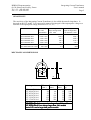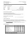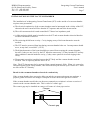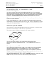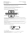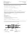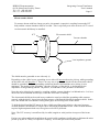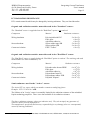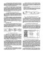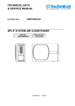
1
bergoz
BERGOZ Instrumentation
Espace Allondon Ouest
01630 Saint Genis Pouilly, France
Tel.: +33-450.426.642
Fax: +33-450.426.643
Instrumentation
Visit our web site at
http://www.bergoz.com
Integrating
Current Transformer
User's Manual
Rev. 3.0
Includes: Active Integrating Current Transformer models
Japan:
U.S.A.:
REPIC Corporation
28-3, Kita Otsuka 1-Chome
Toshima-ku, Tokyo 170-0004
Tel.: 03 - 3918 - 5326
Fax: 03 - 3918 - 5712
[email protected]
GMW Associates
955 Industrial Road
San Carlos, CA 94070
Tel.: (650) 802-8292
Fax: (650) 802-8298
[email protected]
WARNING ! ICT maximum temperature AT ANY TIME: 80°C / 176°F
BERGOZ Instrumentation - 01630 Saint Genis Pouilly, France - Tel.: +33-450.426.642 - Fax: +33-450.426.643
email: [email protected] - http://www.bergoz.com - Registre des Métiers: Bourg-en-Bresse - Registre des ingénieurs: Zurich
TVA-VAT-IVA-USt. Nº FR88414997130 - Sàrl. capital 152K - Siren 414 997 130 R.C.S. Bourg - APE 332B
BERGOZ Instrumentation
01630 Saint Genis Pouilly, France
Tel. +33 - 450.426.642
Fax +33 - 450.426.643
Integrating Current Transformer
User's manual
SUMMARY
INITIAL INSPECTION .................................................................
WARRANTY .............................................................................
ASSISTANCE ...........................................................................
SERVICE & RETURN PROCEDURES .............................................
SAFETY INSTRUCTIONS .............................................................
ORDERING CODES......................................................................
GENERAL DESCRIPTION..............................................................
OPERATING PRINCIPLE...............................................................
MECHANICAL DIMENSIONS.........................................................
SENSITIVITY..............................................................................
ELECTRICAL CONNECTIONS........................................................
POLARITY.................................................................................
CABLE CONNECTION..................................................................
SPECIFICATIONS........................................................................
INSTALLATION ON THE VACUUM CHAMBER..................................
Break in the vacuum chamber electrical continuity...........................
Vacuum chamber impedance...................................................
Wall current by-pass and RF shield...........................................
Thermal protection of the ICT..................................................
Keeping high harmonics of the beam out of the cavity......................
Electrostatic shield...............................................................
ICT RADIATION RESISTANCE.......................................................
ANNEX
Design and preliminary tests of a beam monitor for LEP, K.B.Unser
Page 1
Page
2
2
2
2
3
3
3
4
5
5
6
6
6
6
7
7
8
8
8
9
11
12
BERGOZ Instrumentation
01630 Saint Genis Pouilly, France
Tel. +33 - 450.426.642
Fax +33 - 450.426.643
Integrating Current Transformer
User's manual
Page 2
INITIAL INSPECTION
It is recommended that the shipment be inspected immediately upon delivery. If it is damaged in any
way, contact Bergoz Instrumentation or your local distributor. The content of the shipment should be
compared to the items listed on the invoice. Any discrepancy should be notified to Bergoz
Instrumentation or its local distributor immediately. Unless promptly notified, Bergoz Instrumentation
will not be responsible for such discrepancies.
WARRANTY
Bergoz Instrumentation warrants its beam current monitors to operate within specifications under
normal use for a period of 12 months from the date of shipment. Spares, repairs and replacement parts
are warranted for 90 days. Products not manufactured by Bergoz Instrumentation are covered solely
by the warranty of the original manufacturer. In exercising this warranty, Bergoz Instrumentation will
repair, or at its option, replace any product returned to Bergoz Instrumentation or its local distributor
within the warranty period, provided that the warrantor's examination discloses that the product is
defective due to workmanship or materials and that the defect has not been caused by misuse, neglect,
accident or abnormal conditions or operations. Damages caused by ionizing radiations are specifically
excluded from the warranty. Bergoz Instrumentation and its local distributors shall not be responsible
for any consequential, incidental or special damages.
ASSISTANCE
Assistance in installation, use or calibration of Bergoz Instrumentation beam current monitors is
available from Bergoz Instrumentation, 01630 Saint Genis Pouilly, France. It is recommended to send
a detailed description of the problem by fax.
SERVICE PROCEDURE
Products requiring maintenance should be returned to Bergoz Instrumentation or its local distributor.
Bergoz Instrumentation will repair or replace any product under warranty at no charge. The purchaser
is only responsible for transportation charges.
For products in need of repair after the warranty period, the customer must provide a purchase order
before repairs can be initiated. Bergoz Instrumentation can issue fixed price quotations for most
repairs. However, depending on the damage, it may be necessary to return the equipment to Bergoz
Instrumentation to assess the cost of repair.
RETURN PROCEDURE
All products returned for repair should include a detailed description of the defect or failure, name and
fax number of the user. Contact Bergoz Instrumentation or your local distributor to determine where
to return the product. Returns must be notified by fax prior to shipment.
Return should be made prepaid. Bergoz Instrumentation will not accept freight-collect shipment.
Shipment should be made via Federal Express or United Parcel Service. Within Europe, the
transportation service offered by the Post Offices "EMS" (Chronopost, Datapost, etc.) can be used.
The delivery charges or customs clearance charges arising from the use of other carriers will be
charged to the customer.
BERGOZ Instrumentation
01630 Saint Genis Pouilly, France
Tel. +33 - 450.426.642
Fax +33 - 450.426.643
Integrating Current Transformer
User's manual
Page 3
SAFETY INSTRUCTIONS
The instrument designated as "Integrating Current Transformer" may become RADIOACTIVE when
exposed to ionizing radiations.
It contains :
• Cobalt...........................................................Up to 0.8 Kg
• Iron..............................................................Up to 0.8 Kg
ORDERING CODES
ICT–ppp – ppp – pp:1–xpp –p –p
Inner diameter [mm]:
Standard IDs =
–016
–028
–055
–082
–122
–178
Optional: other ID
Output pulse duration (6σ) [ns]:
Standard: 070
Optional: from 003 to 500
-H
Rad-hard
Connector type:
No suffix SMA
–B
BNC
–L
Lemo
–N
N
Gain:
Nothing: Passive ICT
–x20
Active ICT
Turns ratio:
–05:1
–10:1
–20:1
–50:1
–100:1
GENERAL DESCRIPTION
The Integrating Current Transformer (ICT) is a transformer designed to measure the charge in a very
short pulse with high accuracy. Passive models do not contain any electronics. Active models
incorporate electronics, including radiation-sensitive semiconductors.
The ICT is capable of integrating a very fast pulse with rise time in the order of picoseconds with no
significant loss. This kind of performance is needed, for instance, to measure very short particle
bunches.
The ICT magnetic core and associated windings are essentially noisefree. The measurement noise
–and consequently the measurement resolution– is determined by the signal processing. Active ICT
models have been demonstrated to measure pulsed particle beams with less than 1 nA rms noise.
The Integrating Current Transformer is a capacitively shorted transformer and a fast read out
transformer in a common magnetic circuit.
The magnetic cores are made from thin ribbons of Cobalt / Molybdenum amorphous alloy interleaved
with Nickel / Iron crystalline alloy.
The ICT integrates the signal with a time constant of 1 to 20 nanoseconds, depending on the model.
As a result, rise and fall are both slowed down, the eddy current losses become negligible and the
instrument is a very linear integrator for the very high frequency spectrum typical of a bunched beam
BERGOZ Instrumentation
01630 Saint Genis Pouilly, France
Tel. +33 - 450.426.642
Fax +33 - 450.426.643
Integrating Current Transformer
User's manual
Page 4
GENERAL DESCRIPTION (Cont'd)
signal. The ICT output frequency spectrum is decreased by orders of magnitude in comparison to the
beam frequencies.
Very precise calibration is possible. The ICT's only drawback is that the original shape of the signal is
lost. The ICT delivers its output in a 50 Ω load.
Linearity and beam position sensitivity were tested first in 1987 on the electron/positron collider CESR
at Cornell University1 . A measure of linearity showed an error < 3 x10⁻⁴ for a bunch length variation
of 20% (56ps to 70 ps). A measure of beam position dependency showed an error <10-4 for ±10 mm
of beam axis change (off-center).
The temperature dependence is negligible.
OPERATING PRINCIPLE
The Integrating Current Transformer (ICT) is a transformer designed to measure the charge in a very
fast pulse with high accuracy. It is capable of integrating a pulse with rise time in the order of
picoseconds with no significant loss.
Power feed (Active ICT only)
Amplifier (Active ICT only)
N [turns]
+
+9…15V
Output
50Ω
50Ω
50Ω
Inside ICT
User connection
The ICT is a capacitively shorted transformer coupled to a fast readout transformer in a common
magnetic circuit2 . It delivers a pulse with ca. 20 ns rise time irrespective of the beam pulse rise time.
The ICT output pulse charge is in exact proportion to the beam pulse charge.
1 Design and preliminary tests of a beam monitor for LEP , K.B. Unser, CERN, proceedings of the 1989 IEEE Particle
Accelerator Conference, Vol. 1 page 71.
Measuring Bunch Intensity, Beam Loss and Bunch Lifetime in LEP, K.B.Unser, Proceedings of the 2nd
European Particle Accelerator Conference, 1990, Vol.1, p.786
2
BERGOZ Instrumentation
01630 Saint Genis Pouilly, France
Tel. +33 - 450.426.642
Fax +33 - 450.426.643
Integrating Current Transformer
User's manual
Page 5
SENSITIVITY
The sensitivity of the Integrating Current Transformer is also called the transfer impedance. It
depends on the ICT model. It is expressed in terms of the integral of the output pulse voltage as a
function of the input pulse charge, therefore in V.s/C, or Ω.
Sensitivity
Beam charge to
Beam charge to
in a 50Ω
output charge ratio
output charge ratio
termination
in 50Ω load
in a virtual 0Ω load
Passive models
ICT-XXX-XXX-50:1
0.50 V.s/C
100:1
≈ 50:1
ICT-XXX-XXX-20:1
1.25 V.s/C
40:1
≈ 20:1
ICT-XXX-XXX-10:1
2.50 V.s/C
20:1
≈ 10:1
ICT-XXX-XXX-05:1
5.00 V.s/C
10:1
≈ 5:1
50 V.s/C
1:1
N/A
Active model
ICT-XXX-XXX-10:1-x20
MECHANICAL DIMENSIONS
ID
OD
Ordering code
ICT-016-070-20:1
ICT-028-070-20:1
ICT-055-070-20:1
ICT-082-070-20:1
ICT-122-070-20:1
ICT-178-070-20:1
H
ID
(min.)
16
28
55
82
122
178
OD
(max.)
H
(max.)
Mass
(g)
42
32
110
64
32
180
91
32
300
118
32
400
156
32
520
226
32
980
All dimensions in mm
ICT-XXX-070-10:1 are sometimes larger than -20:1 models
ICT-XXX-070-05:1 are always larger than -20:1 models
Active ICTs can be larger than passive models
BERGOZ Instrumentation
01630 Saint Genis Pouilly, France
Tel. +33 - 450.426.642
Fax +33 - 450.426.643
Integrating Current Transformer
User's manual
Page 6
ELECTRICAL CONNECTIONS
ICT model
Ordering code.................................................. Connector type
Standard
BNC
Lemo
N-type
Active
No suffix.....................................................SMA 50Ω female
-B suffix......................................................BNC 50Ω female
-L suffix..................................................Lemo 00 50Ω female
-N suffix......................................................... N 50Ω female
-x20........................................... Solder pin on Power Feed box
The body of the connector is connected to the shield.
OUTPUT SIGNAL POLARITY
The Integrating Current Transformer is bipolar.
Arrows are printed on the outer surface of the toroid.
Charges (positive) crossing the aperture in the direction of the arrow give positive outputs.
The Active ICT has better linearity for positive pulses than for negative pulses.
POWER SUPPLY (active ICT only)
Power supply
........................................ +9V…15V, 25 mA (0.225 W) @ 9V
CABLE CONNECTION
Most 50Ω coaxial cable types are appropriate to connect the ICT to its measuring instrument.
When short primary pulses are measured (fwhm ≤ ICT output pulse duration / 3), the signal to be
carried by the cable always has the same frequency spectrum, irrespective of the primary pulse rise/fall
time and charge. The fundamental frequency "seen" by the cable is very low:
1
ƒ = ICT output pulse
duration (6σ) I.e ≈14 MHz for standard models ICT-XXX-070...
SPECIFICATIONS
Pulse charge to output ratio
50:1
20:1
10:1
05:1
Input current rise time
<1
<1
<1
<1
ps
Pulse length (max)
2*
2*
2*
2*
µs
Linearity error
< 0.1
<6
< 10
< 20
%
Droop in 50Ω load
<2
<6
< 10
< 20 %/µs
Droop in virtual 0Ω load
<< 1
<1
<1
< 2 %/µs
Eddy current loss
<1
<1
<1
<1
%
Position sensitivity (on axis)
< 0.01 < 0.01 < 0.01 < 0.01 %/mm
Output risetime
≈ 30
≈ 30
≈ 30
≈ 30
ns
Output pulse duration (99% = 6 sigma)
70**
70**
70**
70**
ns
* Longer pulses or macropulses with low-droop special models
** From 3ns to 500ns output pulse length on request
BERGOZ Instrumentation
01630 Saint Genis Pouilly, France
Tel. +33 - 450.426.642
Fax +33 - 450.426.643
Integrating Current Transformer
User's manual
Page 7
INSTALLATION ON THE VACUUM CHAMBER
The installation of an Integrating Current Transformer (ICT) on the outside of a vacuum chamber
requires some precautions.
a) The electrical conductivity of the vacuum chamber must be interrupted in the vicinity of the ICT,
otherwise the wall current will flow thru the ICT aperture and cancel the beam current.
b) The wall current must be diverted around the ICT thru a low impedance path.
c) A fully-enclosing shield must be installed over the ICT and vacuum chamber electrical break to
avoid RF interference emission.
d) The enclosing shield forms a cavity. Cavity ringing at any of the beam harmonics must be
avoided.
e) The ICT must be protected from heat during vacuum chamber bake-out. Its temperature should
never, at any time, exceed 80°C (176°F).
f) The higher harmonics of the beam should be prevented from escaping the vacuum chamber,
because (1) they are not "seen" by the ICT therefore unnecessary, (2) they heat the ICT and any
other conductive material inside the cavity, (3) they cause quarter-wave mode ringing in the
cavity.
g) Electrostatic (capacitive) coupling between the ICT body and the vacuum chamber must be
avoided. This is especially true for Active ICTs.
Note: The ICT does not need to be protected from external magnetic fields. When it is exposed to
external magnetic fields it may saturate; this causes the droop to increase up to a factor of 2. It has
no effect on the ICT linearity.
Break in the vacuum chamber electrical conductivity
If the vacuum chamber does not require bake-out and the vacuum requirements are moderate, a
polymer gasket in-between two flanges is adequate to assure the desired galvanic isolation.
If the vacuum chamber needs bake-out, the most commonly use solution is to braze a section of
ceramic on the vacuum chamber tube. This is called a "ceramic gap".
The ceramic gap may be installed on centre or off-centre of a short pipe section:
Flanges
Ceramic gap
BERGOZ Instrumentation
01630 Saint Genis Pouilly, France
Tel. +33 - 450.426.642
Fax +33 - 450.426.643
Integrating Current Transformer
User's manual
Page 8
INSTALLATION ON THE VACUUM CHAMBER (Cont'd)
Vacuum chamber impedance
The ceramic gap causes a disruption of the impedance seen by the beam. This is particularly
undesirable for leptons accelerators. The most usual corrective measure consists of metallizing the
inside of the ceramic gap. Metallization has been used successfully on many electrons / positrons
accelerators. Depending on the type of current transformer being installed (AC or DC), the
resistance of the desirable metallization varies:
ICT current sensors tolerate a metallization with ca. 1Ω without problem, provided the wall current
bypass is of very low impedance.
If a DC current transformer PCT or MPCT-S is installed over the same ceramic gap, these latter
instruments are adversely affected by an ohmic value R < 100Ω because it shorts the PCT or MPCT
sensor. The commonly used solution is to etch a narrow groove in the metal deposit to prevent DC
conductivity of the gap metallization.
Wall current bypass and RF shield
The two functions of wall current by-pass and RF shield can be performed by a solid metal shield
attached to the vacuum chamber on either side of the electrical break.
The easiest is to make a cylindrical enclosure which splits into two half shells:
The shells can be firmly attached to the vacuum chamber with water hose clamps.
Material can be aluminium, stainless steel or copper. Copper oxidation does not seem to be a
problem.
Thermal protection of the ICT
The ICT must not be heated beyond 80°C. If the vacuum chamber requires bake-out, a thermal
shield must be installed between the vacuum chamber (or the heating sleeves) and the ICT.
The thermal shield can be a simple copper cylinder cooled by water circulating in a copper tube
brazed onto the cylinder.
The water circuit must not pass thru the ICT aperture. It must enter and go out on the same side of
the ICT, otherwise it makes a shorting loop around the ICT toroid.
MAXIMUM STORAGE AND OPERATING TEMPERATURE 80°C (176°F) AT ANY
TIME. The alloy looses its characteristics when heated beyond this temperature.
BERGOZ Instrumentation
01630 Saint Genis Pouilly, France
Tel. +33 - 450.426.642
Fax +33 - 450.426.643
Integrating Current Transformer
User's manual
Page 9
Keeping high harmonics of the beam out of the cavity
The transformer, the gap capacitance and the wall current bypass form together a cavity.
It is important to prevent unnecessary harmonics from entering the cavity:
The beam current flows thru the vacuum chamber.
The wall current follows the conductive vacuum chamber walls.
Transformer
Iw = –Ib
Ib
Ceramic gap
Wall current bypass
The transformer “sees” the wall current Iw. The higher frequencies of the wall current frequency
spectrum will pass thru the capacitance of the ceramic gap, while the lower frequencies will enter the
cavity and induce a flux in the transformer core.
Note that the full charge of the wall current pulse passes thru the cavity, irrespective of the value of
the gap capacitance.
The value C of the gap capacitance determines the higher cutoff frequency of the wall current
entering in the cavity. The -3dB point is obtained when the impedance of the cavity Zcavity is equal to
the impedance of the gap Zgap .
The impedance of the wall current bypass itself can be ignored because it is much lower than the
transformer’s reflected impedance, therefore:
U out
Output
50Ω
FCT
50Ω
User connection
Zcavity = R / N2, where:
R is the load impedance of the transformer = 25Ω (50Ω termination || 50Ω internal load)
N is the transformer’s turns ratio
Example, an ICT with 20:1 turns ratio (i.e. ICT-XXX-20:1), Zcavity = 0.0625 Ω.
BERGOZ Instrumentation
01630 Saint Genis Pouilly, France
Tel. +33 - 450.426.642
Fax +33 - 450.426.643
Integrating Current Transformer
User's manual
Page 10
Keeping high harmonics of the beam out of the cavity (Cont'd)
The gap impedance is determined by its capacitance:
Zgap = 1 / ωC, and ω = 2πƒ
For Zcavity = Zgap : C = N2 / 2πƒR
Example: ICT with 20:1 turns ratio, ƒ-3dB = 1GHz, R = 25Ω : C = 2.54 nF
Different accelerator laboratories use different techniques to obtain the required gap capacitance. A
simple method consists in building a capacitor over the ceramic gap with layers of copper foil
separated by layers of 100µm-thick kapton foil. To obtain the desired capacitance value, the
overlapping area is obtained by:
S = C d / εr εo
Where:
C is the capacitance [F]
S is the area [m2]
d is the dielectric thickness [m]
εr is the relative dielectric constant, 3.5 for Kapton polyimid
εo is the dielectric constant 8.86 x 10⁻¹²
Example, for C = 2.54 nF and d = 100µm and εr = 3.5, S = 82 cm2.
Other laboratories install a capacitive gap bypass with surface-mount capacitors distributed over the
slit. The capacitive bypass is made in two halves for ease of mount:
slit
vacuum
chamber
water hose clamp
smd ceramic
capacitors
Capacitive gap bypass
(lower half)
BERGOZ Instrumentation
01630 Saint Genis Pouilly, France
Tel. +33 - 450.426.642
Fax +33 - 450.426.643
Integrating Current Transformer
User's manual
Page 11
Electrostatic shield
To measure beams with low charge per pulse, electrostatic (capacitive) coupling between the ICT
body and the vacuum chamber must be avoided. This is especially true when an Active ICT is used.
An electrostatic shield may be installed:
ICT
Electrostatic shield
Vacuum chamber
Low impedance ground
The shield must be grounded on one side only (!)
Depending on the cables layout, grounding on one side will increase the noise pick-up, while grounding
on the other side will decrease it. There is no easy way to predict on which side the electrostatic shield
should be grounded: Different grounding conditions must be tried until the noise pickup is at its
minimum. The quality of the grounding –thus the efficiency of the shield– is determined by the
impedance of the grounding scheme. In practice, its inductance is the parameter to minimize.
Note: the noise picked up by capacitive coupling with the vacuum chamber is wideband noise. It is best
observed with a wideband oscilloscope, while the accelerator is running.
The electrostatic shield can be made in any conductive metal, provided the grounding cable connects
properly with the shield. It may have the dual purpose of thermal shield and electrostatic shield. In this
case, one should take care that the cooling water pipes do not bring noise to the shield.
To hold the shield and the ICT sensor in place, while providing good isolation, the space between
vacuum chamber, shield and ICT sensor can be filled with polyurethane foam. If the vacuum chamber
requires high temperature bake-out, fiber glass wool will be preferred.
Note: The ICT accuracy is not affected by its radial, angular or axial position in respect of the beam
axis.
Ferrite cores, tubes and beads installed on the coaxial cable contribute significantly to eliminate the noise
picked up by the ICT body via capacitive coupling. Avoid the split cores when possible.
BERGOZ Instrumentation
01630 Saint Genis Pouilly, France
Tel. +33 - 450.426.642
Fax +33 - 450.426.643
Integrating Current Transformer
User's manual
Page 12
ICT RADIATION RESISTANCE
ICTs contain materials which may be damaged by ionizing radiations. They are listed hereafter:
Organic and radiation-sensitive materials used in the "Standard" sensor:
The "Standard" sensor is supplied when the "Rad-Hard" option is not ordered.
Component
Material
Wiring insulation
Polyvinylchloride PVC
Fiber glass
with rubber adhesive
Silicon rubber tape SIR
Silicon rubber SIR
PTFE "Teflon"
Stress absorbent
Connector isolation
Radiation resistance3
2 x 10⁵ Gy
> 108 Gy
> 106 Gy
5 x 10⁵ Gy
2 x 10⁵ Gy
< 103 Gy
Organic and radiation-sensitive materials used in the "Rad-Hard" sensor:
The "Rad-Hard" sensor is supplied when the "Rad-Hard" option is ordered. The ordering code and
model number are then terminated by -H.
Component
Material
Wiring isolation
Polyether-ether-ketone PEEK
Fiber glass
with rubber adhesive
Polyurethane foam PU
Polyurethane rubber PUR
Polyimid "Kapton"
Stress absorbent
Connector isolation
Radiation resistance
6 x 10⁷ Gy
> 108 Gy
> 106 Gy
5 x 10⁶ Gy
5 x 10⁶ Gy
6 x 10⁷ Gy
Semiconductors used in the "Active" sensor:
The Active ICT is a sensor which part number contains a multiplying factor.
Example: ICT-122-070-10:1-x20.
The lifetime of an "Active" sensor is essentially limited by the radiation resistance of the embedded
bipolar technology amplifier. There is no data available on its radiation resistance.
The above radiation resistance values are indicative only. They do not imply any guarantee of
whatever nature from the manufacturer.
The manufacturer specifically declines any responsibility for any damage, direct or consequential,
caused by ionizing radiations.
3
Compilation of Radiation Damage Test Data, H.Schönbacher et al., CERN 79-04, 79-08, 82-10 and 89-12.
Annex