1
T6200
Ics triplex
User’s Guide
_____________________________________________________________________________________________________
T6200
Compressor Anti-Surge and Capacity Controller
Issue 1
May 2004
Copyright 2004 ICS Triplex
Contents of this manual may not be reproduced
in any form without the written permission of ICS Triplex.
Printed in the United States of America.
Specifications are subject to change without notice.
A/S VIEW MOPS, and T6200
are trademarks of ICS Triplex,
Information furnished by ICS TRIPLEX is believed to be
accurate and reliable. However, no responsibility
is assumed by ICS TRIPLEX for its use.
T6200
USER’S GUIDE
ICS Triplex p/n 9001-0220
Issued May 2004
ICS Triplex, Inc.
4325 West Sam Houston Pkwy. North
Suite 100
Houston, Texas 77043-1219 USA
Phone: 713-353-2400 Fax: 713-353-2401
www.icstriplextmc.com
T6200
User’s Guide
TABLE OF CONTENTS
SECTION 1 – PRODUCT OVERVIEW
Design Structure.............................................................. ................................................................................ 1-3
Analog and Discrete Input/Output .................................. ................................................................................ 1-4
Line Power and Transmitter Power................................ ................................................................................ 1-5
System Security .............................................................. ................................................................................ 1-5
On Line Diagnostics ........................................................ ................................................................................ 1-6
Configuration Security..................................................... ................................................................................ 1-6
Controller Redundancy ................................................... ................................................................................ 1-6
Dual Non-Redundant Controller………………………………………………………………………………….1-6
SECTION 2 – INPUT/OUTPUT CIRCUIT DESCRIPTION
Analog Voltage Inputs..................................................... ................................................................................ 2-3
Analog Current Inputs ..................................................... ................................................................................ 2-4
Analog Current Outputs .................................................. ................................................................................ 2-4
Isolated Discrete Inputs .................................................. ................................................................................ 2-6
Discrete Inputs with Excitation from Controller .............. ................................................................................ 2-6
Discrete Outputs.............................................................. ................................................................................ 2-8
Discrete Outputs with Internal Power............................. ................................................................................ 2-8
Discrete Outputs with External Power............................ ................................................................................ 2-9
Active/Standby Logic....................................................... ................................................................................ 2-9
SECTION 3 – HARDWARE INSTALLATION/MAINTENANCE
Site Selection Considerations......................................... ................................................................................ 3-3
Access Considerations ................................................... ................................................................................ 3-3
T6200 Controller Mounting ............................................. ................................................................................ 3-4
T6200 Controller Electrical Power Wiring ...................... ................................................................................ 3-6
T6200R Subrack Electrical Power Connection ............. ................................................................................ 3-8
Input/Output Hardware Configuration ............................ ................................................................................ 3-9
Signal Wiring.................................................................... ............................................................................... 3-10
Wiring and Jumper Placement for T6200C Channels 1-8 ............................................................................3-12
Wiring and Jumper Placement for T6200C Channels 9-16 .......................................................................... 3-13
Wiring and Jumper Placement for T6200C Channels 17-22, 31, and 32 .................................................... 3-14
Wiring and Jumper Placement for T6200C Channels 23-26 ....................................................................... 3-16
Wiring for T6200C Channels 27-30................................ ............................................................................... 3-17
Wiring and Jumper Placement for T6200D Channels 1-26, 31, and 32 ...................................................... 3-17
Wiring for T6200D Channels 27-30................................ ............................................................................... 3-19
Ethernet Communication Network ................................. ............................................................................... 3-19
Network Security ............................................................. ............................................................................... 3-19
Ethernet Network Connectors………………………………………………………… .................................... 3-19
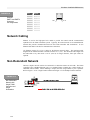
Network Cabling .............................................................. ............................................................................... 3-20
Non-Redundant Network ................................................ ............................................................................... 3-20
Redundant Network………………………………………………………………………………………………3-21
T6200R Subrack Ethernet…… ..................................... ................................................................................ 3-23
Operator Interface Installation ........................................ ............................................................................... 3-24
Firmware Changes.......................................................... ............................................................................... 3-27
Serial Communication Connection................................. ............................................................................... 3-28
3
T6200
User’s Guide
SECTION 4 - SOFTWARE INSTALLANTION
The Micon OPC Server Compact Disc .......................... ................................................................................ 4-2
Install the Packet Driver Software .................................. ................................................................................ 4-2
Install the Micon OPC Server and Related Components............................................................................... 4-5
Ethernet Addresses......................................................... ................................................................................ 4-7
SECTION 5 - T6200 CONTROLLER OPERATION
Push to Activate Switch .................................................. ................................................................................ 5-5
System Start-up............................................................... ................................................................................ 5-6
Replacing Control Boards............................................... ................................................................................ 5-6
Loading Controller Configuration.................................... ................................................................................ 5-8
Watchdog Timer .............................................................. ................................................................................ 5-8
SECTION 6 – HMI-6200 OPERATOR INTERFACE
Preface............................................................................. ................................................................................ 6-2
Overview of HMI-6200 Features .................................... ................................................................................ 6-4
Event Information Processing......................................... ................................................................................ 6-6
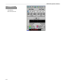
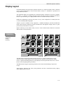
Display Layout ................................................................. ............................................................................... 6-15
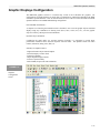
General Display Description ........................................... ............................................................................... 6-18
Graphic Displays Configuration...................................... ............................................................................... 6-21
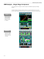
HMI Example – Single Stage Compressor .................... ............................................................................... 6-22
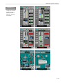
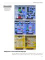
Adaptation of Pre-Defined Displays ............................... ............................................................................... 6-25
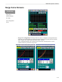
Surge Curve Screens...................................................... ............................................................................... 6-29
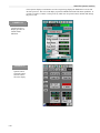
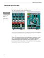
Custom Graphic Screens................................................ ............................................................................... 6-30
Configuring the Security System .................................... ............................................................................... 6-31
Communications.............................................................. ............................................................................... 6-34
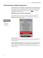
Downloading the Updated Application ........................... ............................................................................... 6-38
SECTION 7 – CONTROL PRIMER
Proportional (P) Action .................................................... ................................................................................ 7-4
Integral (I) Action… ......................................................... ................................................................................ 7-8
Derivative (D) Action ....................................................... ................................................................................ 7-8
Proportional-Plus-Integral (PI) Action……………………………………………………………………………7-9
Proportional-Plus-Derivative (PD) Action………………………………………………………………………..7-10
Proportional-Plus-Integral-Plus-Derivative (PID) Action………………………………………………………..7-11
Interactive and Non-Interactive Control………………………………………………………………………….7-12
Deadtime……………………………………………………………………………………………………………7-13
Cascade Control.............................................................. ................................................................................7-14
Ratio Control.................................................................... ................................................................................7-16
Damping........................................................................... ................................................................................7-16
4
T6200
User’s Guide
SECTION 8 – CONFIGURATION
Preface............................................................................. ................................................................................ 8-3
Configuration Studio........................................................ ................................................................................ 8-4
Running the FBD Configurator Workbench ................... ................................................................................ 8-4
Function Block Diagram (FBD) Editor............................ ............................................................................... 8-10
Miscellaneous Workbench Features.............................. ............................................................................... 8-16
Adaptation of Pre-Defined Configuration ....................... ............................................................................... 8-22
MICON OPC Server Start-up ......................................... ............................................................................... 8-39
SECTION 9 – SPECIFICATIONS
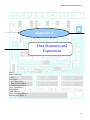
APPENDIX A – DATA STRUCTURES AND EXPRESSIONS
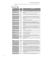
Tags ................................................................................. ................................................................................A-3
Reserved Words.............................................................. ................................................................................A-6
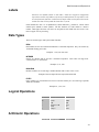
Labels............................................................................... ................................................................................A-7
Data Types ...................................................................... ................................................................................A-7
Logical Operations .......................................................... ................................................................................A-7
Arithmetic Operations...................................................... ................................................................................A-8
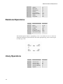
Relational Operations...................................................... ................................................................................A-8
Unary Operations ............................................................ ................................................................................A-8
Expression ....................................................................... ................................................................................A-9
Truth Tables..................................................................... ...............................................................................A-11
Logic Evaluation Rules ................................................... ...............................................................................A-11
Boolean Logic Rules ....................................................... ...............................................................................A-11
APPENDIX B – MODBUS INTERFACE – RS-232
Preface............................................................................. ................................................................................B-2
T6200 MODBUS Functions Supported………………………………………………………………………….B-2
T6200 MODBUS Configuration…………………………………………………………………………………..B-3
5
T6200
6
User’s Guide
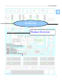
Product Overview
1
Section One
Product Overview
Design Structure 3
Analog and Discrete Input/Output 4
Line Power and Transmitter Power 5
System Security 5
On Line Diagnostics 6
Configuration Security 6
Controller Redundancy 6
Dual Non-Redundant Controller 6
1-1
Product Overview
1-2
Product Overview
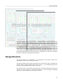
PRODUCT OVERVIEW
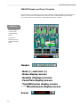
The T6200 Controller is made up of two parts: The Operator Interface and the T6200 Controller.
The Operator Interface with the Windows CE platform enables complete interaction with the T6200
Controller. Through the touch screen and LCD display users can change setpoints, outputs, start/stop
devices, scroll through trends, or acknowledge alarms. The T6200 Controller functions as a
multiapplication Controller or intelligent RTU capable of performing all data acquisition, continuous
control, batch control, logic control and RTU requirements. Each T6200 Controller includes 999
function blocks in which control/logic functions can reside. The integral input/output (I/O) section
of each T6200 Controller accommodates 32 I/O points. The large library of functions (over 100) and
the practically unlimited number of blocks allow for pre-configuration of a wide variety of strategies
by the factory and permits field application optimization.
Design Structure
The Operator Interface is an embedded PC. It is independent of the T6200 Controller and it
communicates with the T6200 Controller via Ethernet.
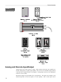
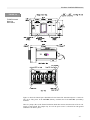
The T6200 Controller consists of three physical parts: the control board/s (single or redundant), the
controller housing, and the termination panel. Refer to Figure 1-1. The termination panel may also
include a remote termination panel for the I/O connections.
The control boards are a single printed circuit board design. The board contains the microprocessor
circuitry, the memory chips, the communication interfaces, and the input/output conditioning
components. Primary and backup control boards are identical.
1-3
Product Overview
FIGURE 1-1.
T6200 Unit Controller
Analog and Discrete Input/Output
Analog inputs can be either current or voltage. High common mode (200 Volts) amplifiers are
utilized. Each input has a separate input amplifier. Also, each two wire transmitter input (4-20mA)
is provided with a separate internal 24 volt regulator. Analog outputs source up to 20 milliamperes
to the user’s receiver (load).
Most discrete inputs are opto-isolated (refer to specifications). The sample rate resolution of one
millisecond provides for first out sequence of events capability. Three of these inputs can be
1-4
Product Overview
configured as frequency/pulse inputs. Discrete outputs are transistor configurations. A separate
internal 24 volt regulator is supplied for each input/output.
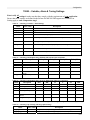
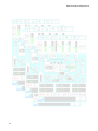
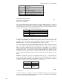
The internal I/O section of the Controller accommodates 32 I/O points. Refer to Table 1-1 for I/O
channel assignment information.
TABLE
TABLE1-1
1-1..
I/O Channel Numbers
Type
Input/Output
Channel Assignments
1-8
9 – 16
17 - 22
23-26
27 - 30
31 - 32
Discrete
I/O *
Analog
I/O
Analog
Output
Discr
I/O*
Discrete
Input
Discr
I/O*
Analog
T6200C
Analog
or
Input
Discrete
Input
T6200D
Discrete I/O
* Channels 22, 31 and 32 can also be configured as a frequency/pulse input. Channel 32 can also be
configured as a frequency/pulse output.
The process signals supported by the T6200 Controllers are:
•
Analog Inputs (4-20 mA, ±20 mA, ±10 Vdc) internally or externally powered
•
Analog Outputs (4-20 mA, 0-20 mA)
Discrete Inputs (On-Off contacts) internally or externally powered
Discrete Outputs - internally or externally powered
Pulse Inputs (up to 25 kHz)
Line Power and Transmitter Power
The T6200 Controllers operate on 26 Vdc power. The T6200R subrack supplies redundant AC to
DC power supplies or the 26 Vdc can be obtained from any other reliable power source. Terminal
blocks are provided on the termination panel for primary and secondary (redundant) 26 Vdc power
input. Power for field transmitters, I/Ps, field switches, etc., is distributed through the T6200
Controller eliminating separate input/output power supplies and circuitry.
Both power supplies operate continuously. If one unit fails, it is not necessary to switch to the other
power supply. Both of the 26 Vdc sources are diode-isolated in the T6200 Controller to prevent the
failure of one from affecting the other. The supplies feed redundant power distribution traces on the
termination panel.
System Security
The Controller maximizes its reliability and availability by a design incorporating complete
redundancy of memory, intelligence, communication, and power. The redundancy includes total
process input/output circuitry backup. And, since each termination panel can accommodate both the
primary and backup control boards, the architecture allows for simple plug-in of the redundant
control board. No wiring or cabling is required for redundant configurations.
The integral backup communication link of each unit assures that both control boards (primary and
backup) maintain the same data base. Each control board has its own on-line, sophisticated
1-5
Product Overview
diagnostics and also monitors the status of the other control board which provides for a reliable
transfer and redundancy scheme.
On Line Diagnostics
The T6200 Controller has on-line diagnostics designed to identify failures quickly. On all (primary
and backup) operator interfaces, highways, local communications, the Controller run diagnostics on
a continuous basis. These routines continuously check the status of critical device functions to detect
failures.
If a failure is detected an alarm is activated to inform the operator and the backup unit is enabled.
Configuration Security
The T6200 Controllers maintain identical configuration at all times. At startup, when both control
boards are powered up, the backup control board’s memory is always cleared, and the active control
board transfers the configuration to the backup control board through the backup serial link, if it has
a backup control board.
During operation (runtime), if new configuration is downloaded (to active control board), it
automatically goes to both the primary and the backup control board. Thus configuration integrity is
achieved and there are no mismatches.
Uninterrupted communication and control is provided by automatically transferring all configuration
and communications of the active control board to the backup redundant control board. There is a
complete transparency in the redundant control board. Apart from notification of failure, there is no
change in the operator interface.
Controller Redundancy
The T6200 Controller redundancy concept allows the user to simply plug-in a backup control board
side-by-side with the primary control board. The user has no installation or cable connection
requirements. Termination panel data links enable the backup to copy the input/output and control
configuration of the primary control board and to assume virtually immediately the input/output and
control functions in case of a primary malfunction.
Each control board contains, in addition to the input/output functions, an extensive library of control
algorithms. Thus, the T6200 Controllers can be configured as totally stand-alone intelligent
controllers or RTUs. This minimizes dependency on communications, resulting in high reliability.
Dual Non-Redundant Controller
The T6200 Dual Non-Redundant Controller concept allows the user to have two independent
controllers (a primary and a second controller) in one chassis thereby reducing the required panel
space by half. With this option, two T6200-C Controller cards or two T6200-D Controller cards or a
T6200-C and a T6200-D Controller card may be plugged into a single chassis. Two Remote I/O
Termination Panels (one for the primary controller and one for the second controller) are required
with this concept. The Dual Non-Redundant Controller option should only be used when controller
redundancy is not foreseen as a requirement.
1-6
Input/Output Circuit Description
2
Section Two
Input/Output Circuit Description
Analog Voltage Inputs 3
Analog Current Inputs 4
Analog Current Outputs 4
Isolated Discrete Inputs 6
Discrete Inputs with Excitation from Controller 6
Discrete Outputs 8
Discrete Outputs with Internal Power 8
Discrete Outputs with External Power 9
Active/Standby Logic 9
2-1
Input/Output Circuit Description
2-2
Input/Output Circuit Description
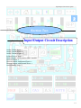
INPUT/OUTPUT CIRCUIT
DESCRIPTION
Each control board in the T6200 Controller incorporates the µP, memory, communications and I/O
circuitry. Separate I/O modules are not required.
Analog Voltage Inputs
Up to 20 channels in the T6200-C Controller can be configured with field changeable jumpers for
voltage inputs. In reference to Figure 2-1, the input amplifier does not have galvanic isolation but it
appears to have it in most applications because of its high common-mode voltage and its high input
resistance. The 100 volt transient absorbers on each input will allow up to 100 volts dc or 75 volts
ac (rms, sine wave) continuously or up to 104 volts impulse voltage to enter the amplifier. The
amplifier will continue to operate with up to 200 volts on its inputs.
Each input has a separate input amplifier. The output of each of these amplifiers passes to the
analog switch. Only one of these inputs is selected at one time. The selected signal continues to the
programmable gain amplifier (PGA). The microprocessor selects the optimum gain setting for the
PGA. The possible input full scale ranges that can be selected are 0.625, 1.25, 2.5, 5, and 10 volts.
Inputs may be either polarity.
The voltage input configuration can be used as a current input by putting a resistor between the “+”
and “-” input terminals. Use a 250 ohm resistor for a 4 to 20 milliampere loop and a 100 ohm
resistor for a 10 to 50 milliampere loop.
2-3
Input/Output Circuit Description
Termination
Panel
Primary Control Board
200 Volt
Common-mode
Amplifier
1A
FIGURE 2-1
100V
Analog Voltage
Input
Analog
Switch
Programmable
Gain Amplifier
To ADC
1A
100V
Analog
Voltage
Input
Backup Control Board
200 Volt
Common-mode
Amplifier
1A
100V
Analog
Switch
Programmable
Gain Amplifier
To ADC
1A
100V
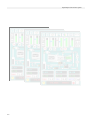
Analog Current Inputs
The current input is similar to the voltage input with 250 ohm resistor across the amplifier inputs. Field
changeable jumpers are used to select between voltage or current input. The maximum continuous input
current is 20 mA and 40 mA momentary. Refer to Figure 2-2. Also the gain is increased in the PGA by a
factor of two when a backup control board is present, to compensate for the decrease in voltage that the
additional 250 ohm resistor will cause.
When an isolated two-wire 4 to 20 milliampere transmitter is used, the circuit shown in Figure 2-3 may be
used. In this configuration a separate internal +24 volt voltage regulator is used for each transmitter. Each
voltage regulator has thermal, reverse voltage, and short-circuit protection. In this arrangement, one end
of the 250 ohm resistor is connected to circuit common. The two-wire 4-20 mA represents the standard
analog input jumper selection.
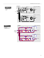
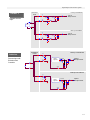
Analog Current Outputs
The T6200 Controller can be configured from four to eight current outputs. The current output will source
from 0 to 20 milliamperes to the user's receiver (load). The receiver must share the same circuit common
as the T6200 Controller. The maximum receiver resistance is 1000 ohms.
In reference to Figure 2-4, the digital to analog converter (DAC) receives a digital value from the
microprocessor and converts it to an analog voltage. The voltage to the current converter, combined with
transistor Q1 and the 50 ohm resistor, converts the voltage to a current signal.
The output of the primary and backup control boards are connected together on the Controller termination
panel. The output is only enabled in the active control board. The diode is used to block the current from
the active control board.
2-4
Input/Output Circuit Description
Termination
Panel
FIGURE 2- 2
200 Volt
Common-mode
Amplifier
Primary Control Board
Analog
Switch
Programmable
Gain Amplifier
Analog Current
Input
To ADC
4-20 MA
Input
200 Volt
Common-mode
Amplifier
Backup Control Board
Analog
Switch
Programmable
Gain Amplifier
To ADC
FIGURE 2- 3
Primary Control Board
Termination
Panel
1A
Two-Wire
Transmitter Input
Voltage
Regulator with
short-circuit
protection
24 VDC
100V
Analog
Switch
1A
100V
Two-Wire
Transmitter
Input
Programmable
Gain Amplifier
To ADC
250
OHM
X2
Backup Control Board
1A
Voltage
Regulator with
short-circuit
protection
24 VDC
100V
Analog
Switch
1A
100V
250
OHM
+V
Programmable
Gain Amplifier
To ADC
X2
2-5
Input/Output Circuit Description
Termination
Panel
Primary Control Board
FIGURE 2-4.
+25.2V
Voltage to
Current
Converter
DAC
Analog Current
Output
125mA
50
OHM
From
Microprocessor
Reset
Analog
Current
Output
Inhibit from Figure 2-9
Active from Figure 2-9
Primary Control Board
+25.2V
Voltage to
Current
Converter
Q1
DAC
125mA
50
OHM
From
Microprocessor
Reset
Inhibit from Figure 2-9
Active from Figure 2-9
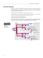
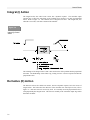
Isolated Discrete Inputs
The T6200-C Controller can be configured for up to 16 isolated discrete inputs. The T6200-D Controller
can be configured for up to 28 isolated discrete inputs in addition to the four internally power discrete
inputs. The resistor, in series with the input, is used to limit the maximum current to less than 6.5
milliamperes. In reference to Figure 2-5, the resistor across the opto-isolator is used to increase the
minimum input current to greater than one milliampere.
The opto-isolator provides electrical isolation between inputs and other circuits. Each input is protected
with fuses. A 100 volt transient absorber is provided on each input terminal to prevent arcing between
conductors on the circuit board. The maximum voltage that can be applied continuously is 38 volts dc or
30 volts ac (rms, sine wave). Discrete input channels 22, 31, and 32 can be used as frequency inputs, with
input frequencies up to 25 kHz. Other discrete inputs can be used as frequency inputs with input
frequencies up to 500 Hz.
Discrete Inputs with Excitation from Controller
The discrete input is similar to the isolated discrete input above, without the isolation. The input is
internally powered. In this configuration a separate internal +24 volt regulator is provided for each dry
contact input. Each voltage regulator has thermal, reverse voltage, and short circuit protection. The
regulator supplies up to five milliamperes.
A contact closure between + and – terminals will activate the input. Refer to Figure 2-6. The internally
powered discrete input represents the standard discrete input jumper selection. The T6200 Controller has
a minimum of four internally powered discrete inputs.
2-6
Input/Output Circuit Description
Termination
Panel
FIGURE 2- 5.
Primary Control Board
1A
Input to
Microprocessor
100V
Isolated Discrete
Input
1.8K
1A
4.7K
100V
Power
Backup ControlBoard
1A
Input to
Microprocessor
100V
1.8K
1A
4.7K
100V
FIGURE 2-6.
Termination
Panel
Primary Control Board
1A
100V
Discrete Input with
Excitation from
Controller
1A
Voltage
Regulator
24 VDC
Input to
Microprocessor
1.8K
4.7K
Backup Control Board
1A
100V
1A
Voltage
Regulator
24 VDC
Input to
Microprocessor
1.8K
4.7K
2-7
Input/Output Circuit Description
Discrete Outputs
The T6200-C Controller can be configured for up to eight discrete outputs. The T6200-D Controller can
be configured for up to 28 discrete outputs. A 100 volt transient absorber is connected on each terminal to
protect the output transistor and to prevent arching between conductors on the circuit board. Each
terminal is protected with a one ampere fuse.
The output transistor in the standby (not ACTIVE) control board is always open.
Discrete output 32 can be used as frequency output, with output frequencies up to 10 kHz. Other discrete
outputs can be used as frequency outputs with output frequencies up to 100 Hz.
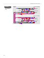
Discrete Outputs with Internal Power
In reference to Figure 2-7, a separate internal +24 volt voltage regulator is provided for each output. Each
voltage regulator has thermal, reverse voltage, and short-circuit protection. The regulator can supply 24
Vdc power for a load up to 20 milliamperes continuously and 100 milliamperes momentarily.
FIGURE 2-7
Termination
Panel
Discrete
Output with
Internal Power
Primary Control Board
1A
24 VDC
100V
Voltage
Regulator with
short-circuit
protection
1A
Active from Figure 2-9
Latch
Output from
RS
Microprocessor
100V
LOAD
<20 mA
Inhibit from Figure 2-9
1A
24 VDC
100V
Voltage
Regulator with
short-circuit
protection
Backup Control Board
1A
100V
Active from Figure 2-9
Latch
Output from
RS
Microprocessor
Inhibit from Figure 2-9
2-8
Input/Output Circuit Description
Discrete Outputs with External Power
In reference to Figure 2-8, the discrete transistor output with an external power source can sink up to 0.25
amperes continuously and one ampere momentarily. The maximum voltage that can be applied
continuously is 38 volts DC. The return (-) of the external power source must be connected to the “-”
input or “-” power terminal of the T6200 Controller.
Termination
Panel
FIGURE 2-8.
Primary Control Board
1A
100V
Discrete Output
with External
Power
1A
Active from Figure 2-9
Latch
RS
Output from
Microprocessor
Inhibit from Figure 2-9
Load
<0.25A
Backup Control Board
1A
Active from Figure 2-9
Latch
100V
1A
RS
Output from
Microprocessor
Inhibit from Figure 2-9
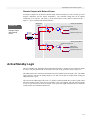
Active/Standby Logic
The active/standby logic determines which control board (primary or backup) is active and if the outputs
are active. Only one control board can assume the active role at any given time. Refer to Figure 2-9.
The inhibit signal is true when the control board is not active and the system fail signal is true. The inhibit
signal when true will reset the analog outputs to zero and reset the discrete output latches causing the
output transistors to open.
The only time the inhibit signal can be true, in a primary control board that does not have a good control
board in its backup position, is the first 0.2 second after power is first applied. This will allow the outputs
to reset on power up and to freeze the outputs if the system fail signal should become true when the
control board is active and must remain active.
2-9
Input/Output Circuit Description
FIGURE 2-9
Active/Standby
Logic
Termination
Panel
Primary Control Board
Active
ACT
LED
Inhibit
Power Up
Reset
System Fail
OUT LED
Activate
switch
Backup Control Board
Active
ACT
LED
Inhibit
Power Up
Reset
System Fail
OUT LED
Activate
switch
2-10
Hardware Installation/Maintenance
3
Section Three
Hardware Installation/Maintenance
Site Selection Considerations 3
Access Considerations 3
T6200 Unit Automating System Mounting 4
T6200 Controller Electrical Power Wiring 6
T6200R Subrack Electrical Power Connection 8
Input/Output Hardware Configuration 9
Signal Wiring 10
Wiring and Jumper Placement for T6200-C Channels 1-8 12
Wiring and Jumper Placement for T6200-C Channels 9-16 13
Wiring and Jumper Placement for T6200-C Channels 17-22, 31, and 32 14
Wiring and Jumper Placement for T6200-C Channels 23-26 16
Wiring for T6200-C Channels 27-30 17
Wiring and Jumper Placement for T6200-D Channels 1-26, 31, and 32 17
Wiring for T6200-D Channels 27-30 19
Ethernet Communication Network 19
Network Security 19
Ethernet Network Connectors 19
Network Cabling 20
Non-Redundant Network 20
Redundant Network 21
T6200R Subrack Ethernet 23
Operator Interface Installation 24
Firmware Changes 27
Serial Communication Connection 28
3-1
Hardware Installation/Maintenance
3-2
Hardware Installation/Maintenance
Hardware
Installation/Maintenance
`
Site Selection Considerations
The T6200 Controller requires following conditions during normal operation:
32 to 122º F (0 to 50º C)
5 to 96% Relative humidity
Protection from direct contact with water, chemicals, and conductive dust.
Protection from exposure to sulfur compounds, acid, other corrosive or reactive vapors or
fumes, dust, and lint.
For estimating heat load requirements, the T6200 Controller dissipates a maximum of 10 BTU/hr.
(or 24 KGM-CAL/Hr) to the inside of the control panel.
Access Considerations
There are very few restrictions on the mounting position of the T6200 Controller. The following should
be taken into consideration:
All electrical power and input/outputs are connected on the rear termination panel.
Because as many as 70 conductors and four cables can be terminated to each T6200 Controller
adequate wireway space should be provided.
The T6200 Controller is operated from the front of the unit with switches on the
bottom. The Operator Interface slides up 0.5 in. (12 mm) to remove.
3-3
Hardware Installation/Maintenance
The control boards slide out the front of the unit.
To ensure a proper viewing angle, the Controller should be installed approximately
64 inches (1.6 m) above the floor.
Outdoor installation is not recommended. However, for outdoor installations, the
face of the Controller should be shielded from direct sunlight, since bright light produces a
poor display contrast.
T6200 Controller Mounting
T6200 Controller Mounting
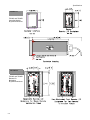
Figure 3-1 provides mounting dimensions for the T6200 Controller. Dimensions are shown in inches
(mm).
Remove Operator Interface by pushing up and pulling out at the bottom. Disconnect cable
from Operator Interface
Use the two Phillips head screws and clamps to mount the T6200 Controller in the user’s
panel.
When the T6200 Controller is positioned properly, hand-tighten both clamps in place. Note:
Do not exceed 15 in-lbs (17 cm-kgs) of torque on panel clamp screws.
The panel cut-out dimensions, as well as the Operator Interface front outline dimensions are shown in
Figure 3-2. The T6200 Controller would normally be mounted in a vertical position.
Figure 3-3 provides mounting dimensions for the optional Remote I/O Termination Panel. The I/O
cable that connects the T6200 Controller to the Remote I/O Termination Panel is 6 ft. (2m) long.
Dimensions are shown in inches (mm). The Remote I/O Termination Panel can be snapped onto a user
supplied standard 35 mm DIN rail.
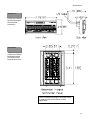
T6200R Subrack Mounting
Each T6200R Subrack Housing accommodates up to six redundant T6200 Controllers. The subrack
may also include two power supplies, Operator Interface, and two Ethernet hubs. Refer to Figure 3-4
for T6200R Subrack mounting dimensions. The subrack should be mounted in a EIA standard 19 inch
rack. Refer to Section Nine Specifications for more detailed physical dimensions.
3-4
Hardware Installation/Maintenance
FIGURE 3-1.
T6200
Mounting
Dimensions
4.30 [109]
2.74 [69]
2.68 [68]
FIGURE 3-2.
T6200 Controller
Panel Cutout
Dimensions
1.72 [44] MIN
OPERATOR INTERFACE
PANEL CUTOUT
5.44 [138]
5.95 [151]
5.50 [139]
1.375 [35]
3-5
Hardware Installation/Maintenance
FIGURE 3-3
Remote I/O
Terminal Panel
Mounting
Dimensions
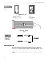
T6200 Controller Electrical Power Wiring
The guidelines below should be followed when wiring the power to the T6200 Controller:
The maximum wire size is 16 AWG stranded.
All wiring should be multi-stranded annealed copper with insulation that meets the
requirements of all applicable electrical codes.
AC power wiring should be run in a separate conduit from the T6200 Controller power and the
I/O.
The stripped portion of the wire should be 3/16” (5 mm) long.
Wires should be inserted in the clamp type terminals until they touch the internal stops. The
terminal screw should be tightened while holding the wire in place. Check for proper clamp
pressure with a gentle tug on the wire.
Electrical power should be provided from a redundant, highly reliable, dedicated 26 Vdc power
source.
Power consumption is 15 watts for the T6200 Controller and 15 watts for the Operator
Interface, not including field devices.
The T6200 Controller has redundant 26 Vdc power supply connections.
3-6
Hardware Installation/Maintenance
FIGURE 3-4
T6200R Subrack
Mounting
Dimensions
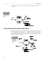
Figure 3-5 shows the internal power distribution for the T6200 Unit Automation System. Connect 26
Vdc (18-32 Vdc) power to the 26V PRI (Primary) terminals and to the 26V SEC (Secondary)
terminals.
There is a jumper (W1) on the T6200 Termination Panel that connects the minus side of the 26 volt
supply to earth ground. This jumper may be cut if the power source is referenced to earth ground
somewhere else in the system.
3-7
Hardware Installation/Maintenance
FIGURE 3-5
Internal Power
Distribution
T6200R Subrack Electrical Power Connection
Once the T6200R Subrack is mounted, plug the included external power supply’s DC power cord into
the matching power jack on each of the Ethernet Hub’s rear panel. The Ethernet Hub shelf may be
removed to connect the power. Plug each of the power supply’s transformers into an AC receptacle that
is six feet (two meters) or less away. The green “Pwr” LED should light up.
Refer to the guidelines in T6200 Controller Electrical Power Wiring above and Figure
3-6 and connect AC power wiring to each of the 26 Vdc Power Supplies.
The 26 Vdc power to the T6200 Controllers and Operator Interface is usually prewired as shown in
Figure 3-6.
Figure 3-6
T6200R Subrack
Power Wiring
3-8
Hardware Installation/Maintenance
Input/Output Hardware Configuration
There are several different ways the hardware can be configured for each input/output. Refer to
Section Two Input/Output Circuit Description for details on each configuration. The different
configurations are achieved by the placement of jumpers (shorting bars) on a multi-pin headers located
on the printed circuit board. Each channel has a separate header and can be configured independently.
To access the jumpers:
CAUTION
Unplug the optional front panel Operator Interface
Carefully slide the printed circuit board out the front of the chassis.
The Controller contains parts susceptible to damage by electrostatic
discharge. Normal precautions should be taken to avoid high static
voltages.
When facing the component side of the printed circuit board with the LEDs on the left, the
headers/jumpers will be at the right Pin one on the headers will be as shown in the illustrations. Pin one
also has a square pad on the circuit side of the printed circuit board. Refer to Figure 3-7 for T6200C.
Refer to Figure 3-11 for T6200D.
FIGURE 3-7.
T6200C Control
Board
The headers may vary from input/output group to group. All the headers are oriented the same way
within one group. A group is where a`ll consecutive inputs/outputs have the same configuration
options. For example, channels one through eight are in the same group.
3-9
Hardware Installation/Maintenance
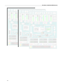
Signal Wiring
Individually shielded wires are not required (except for frequency inputs). Twisted pairs and overall
cable shields are recommended. Each multipair cable should contain a few pairs of spare wires. Shields
and unused conductors should be terminated to ground at Controller end only. Refer to appropriate
Wiring and Jumper Placement.
The following general guidelines apply to all signal wiring discussed in the following paragraphs.
FIGURE 3-8
Integral
Termination
Panels
3-10
Wire size range for the terminal panel is 26-16 AWG stranded; recommended wire size range
is 18-14 AWG.
Wire size range for the remote I/O terminal is 26-14 AWG stranded; recommended wire size
range is 18-14 AWG.
All wiring should be multi-stranded annealed copper with insulation that meets the
requirements of all applicable electrical codes.
Keep all wire runs as short and direct as possible. Long wire runs are vulnerable to picking up
stray electrical noise. Use care when running signal wiring near to or crossing conduit or
wiring that supplies power to motors, solenoids, lighting, horns, bells, etc.
Avoid bringing signal wiring into junction boxes which contain other wiring.
AC power wiring should be run in a separate conduit from the signal wiring.
The stripped portion of the wires should be 5/16” (8 mm) long.
Wires should be inserted in the clamp type terminals until they touch the internal stops. The
terminal screw should be tightened while holding the wire in place. Check for proper clamp
pressure with a gentle tug on the wire.
Hardware Installation/Maintenance
FIGURE 3-9
Redundant
Remote I/O
Termination
Panel
FIGURE 3-10
Dual
Non-Redundant
Remote I/O
Termination
Panel
3-11
Hardware Installation/Maintenance
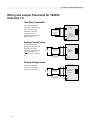
Wiring and Jumper Placement for T6200C
Channels 1-8
Two-Wire Transmitter
T6200C Controller
This wiring and jumper
placement is normally used
with isolated two-wire
transmitters where the
transmitter power is
supplied by the Controller.
Refer to Figure 2-3.
24 Vdc
Supply
+
+
4-20 mA
Two-Wire
Transmitter
(Isolated)
-
1
mA Input
Factory
(reference to
Default
common
through resistor)
-
SHLD
Analog Current Inputs
This wiring and jumper
placement is normally used
with four-wire current
transmitters when the power
is not supplied by the
Controller. Refer to Figure
2-2.
T6200C Controller
+
+
1
Power
Source
mA Input
(Isolated from
common)
4-20 mA
Transmitter
Transmitter output
may be referenced
to common
-
SHLD
Analog Voltage Inputs
T6200C Controller
This wiring and jumper
placement is for voltage
inputs. Refer to Figure 2-1.
+
1
Power
Source
DC Voltage Input
(Isolated from
common)
DC Voltage
Transmitter
Transmitter output
may be referenced
to common
3-12
+
-
SHLD
Hardware Installation/Maintenance
Wiring and Jumper Placement for T6200C
Channels 9-16
Two-Wire Transmitter
T6200C Controller
This wiring and jumper
placement is normally used
with isolated two-wire
transmitters where the
transmitter power is
supplied by the Controller.
Refer to Figure 2-3.
24 Vdc
Supply
+
+
4-20 mA
Two-Wire
Transmitter
(Isolated)
-
1
mA Input
(reference to
Factory
common
Default
through resistor)
-
SHLD
Analog Current Input
This wiring and jumper
placement is normally used
with four-wire current
transmitters when the power
is not supplied by the
Controller. Refer to Figure
2-2.
T6200C Controller
+
Power
Source
+
1
mA Input
(Isolated from
common)
4-20 mA
Transmitter
Transmitter output
may be referenced
to common
-
SHLD
Analog Voltage Input
This wiring and jumper
placement is for voltage
inputs. Refer to Figure 2-1.
T6200C Controller
+
Power
Source
+
1
DC Voltage Input
(Isolated from
common)
DC Voltage
Transmitter
Transmitter output
may be referenced
to common
-
SHLD
3-13
Hardware Installation/Maintenance
Discrete Inputs with Excitation from Controller
This wiring and jumper
placement is for discrete
(On/Off) inputs. The
Controller supplies 24 VDC
power for the input. Refer to
Figure 2-6.
Alternate
Open Collector
Transistor
+
T6200C Controller
Discrete Input
(24 Vdc/5 mA 1
excitation)
-
Circuit
Common
Contact
Isolated Discrete Inputs
This wiring and jumper
placement is for discrete
(On/Off) inputs. The
discrete inputs are isolated
from other circuits and the
external power for the input
is either 18-32 Volt AC or
DC. Refer to Figure 2-5.
T6200C Controller
+
1
Contact
Power Source
18 V to 32 V
ac/dc
Discrete Input
(Optically
coupled)
Polarity
Arbitrary
-
Wiring and Jumper Placement for T6200C
Channels 17-22, 31, and 32
Discrete Inputs with Excitation from Controller
T6200C Controller
Discrete Input
+ (24 Vdc/5 mA
excitation)
This wiring and jumper
placement is for discrete
(On/Off) inputs. The
Controller supplies 24
VDC power for the input.
Refer to Figure 2-6.
Alternate
Open Collector
Transistor
Contact
-
Circuit
Common
1
Factory
Default
Isolated Discrete Inputs
This wiring and jumper
placement is for discrete
(On/Off) inputs. The
discrete inputs are isolated
from other circuits and the
external power for the
input is either 18-32 Volt
AC or DC. Refer to
Figure 2-5.
3-14
T6200C Controller
+
Contact
Power Source
18 V to 32 V
ac/dc
Discrete Input
(Optically
coupled)
Polarity
Arbitrary
-
1
Hardware Installation/Maintenance
Frequency Inputs
This wiring and jumper
placement is for a
frequency/pulse
preamplifier input with
the Controller supplying
the power (Channel 22,31
and 32).
T6200C Controller
+
24 Vdc
Supply
OUT
-
Discrete
Input
COM
SHLD (Circuit Common)
PWR
Frequency/Pulse
Preamplifier or other
Discrete Device
0-25KHz only for
Channels 22, 31 &
32
1
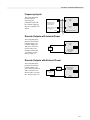
Discrete Outputs with Internal Power
This wiring and jumper
placement is for discrete
(On/Off) outputs. The
Controller supplies 24
VDC power for the 20
mA max load. Load
Example: Entrelec RB
131 (010055.23) relay.
Refer to Figure 2-7.
T6200C Controller
+
+
Discrete
Load
<20 mA
-
24 Vdc
Supply
1
Discrete Output
(Open Collector
Transistor)
Discrete Outputs with External Power
This wiring and jumper
placement is for discrete
(On/Off) outputs. The
power source (less than 38
VDC) is external. The
discrete load is 0.25 Amp
max. Refer to Figure 2-8.
T6200C Controller
+
+
Discrete
Load
<0.25 A
-
Discrete Output
+ (Open Collector
Transistor)
Power Source
<38 Vdc
-
1
-
Circuit
Common
3-15
Hardware Installation/Maintenance
Wiring and Jumper Placement for T6200C
Channels 23-26
Two-Wire Transmitter
This wiring and jumper
placement is normally
used with isolated
two-wire transmitters
where the transmitter
power is supplied by the
Controller. Refer to
Figure 2-3.
T6200C Controller
24 Vdc
Supply
+
+
4-20 mA
Two-Wire
Transmitter
(Isolated)
-
1
mA Input
Factory
(reference to
Default
common
through resistor)
-
SHLD
Current Inputs
This wiring and jumper
placement is normally
used with four-wire
current transmitters when
the power is not supplied
by the Controller. Refer
to Figure 2-2.
T6200C Controller
+
Power
Source
+
1
mA Input
(Isolated from
common)
4-20 mA
Transmitter
Transmitter output
may be referenced
to common
-
SHLD
Analog Voltage Inputs
This wiring and jumper
placement is used for
voltage input. Refer to
Figure 2-1.
T6200C Controller
+
Power
Source
+
1
DC Voltage Input
(Isolated from
common)
DC Voltage
Transmitter
Transmitter output
may be referenced
to common
-
SHLD
Analog Current Outputs
0-20mA (4-20mA)
Analog current outputs.
Refer to Figure 2-4.
T6200C Controller
+
+ mA Output
4-20 mA or
0-20 mA
Receiver
(Isolated)
-
-
Circuit
Common
SHLD
3-16
1
Hardware Installation/Maintenance
Wiring for T6200C
Channels 27-30
Analog Current Outputs
0-20mA (4-20mA)
Analog current outputs.
Refer to
Figure 2-4.
Channels 27-30 do not
have jumper placements.
T6200C Controller
+ mA Output
+
4-20 mA or
0-20 mA
Receiver
(Isolated)
-
-
Circuit
Common
SHLD
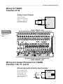
FIGURE 3-11
T6200D Control
Board
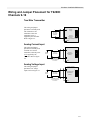
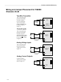
Wiring and Jumper Placement for T6200D
Channels 1-26, 31, and 32
Discrete Input with Excitation from Controller
This wiring and jumper
placement is for discrete
(On/Off) inputs. The
Controller supplies 24
VDC power for the input.
Refer to Figure 2-6.
+
Alternate
Open Collector
Transistor
T6200D Controller
Discrete Input
(24 Vdc/5 mA
excitation)
Contact
-
Circuit
Common
1
Factory
Default
3-17
Hardware Installation/Maintenance
Isolated Discrete Input
This wiring and jumper
placement is for discrete
(On/Off) inputs. The
discrete inputs are isolated
from other circuits and the
external power for the
input is either 18-32 Volt
AC or DC. Refer to
Figure 2-5.
T6200D Controller
+
Contact
Power Source
18 V to 32 V
ac/dc
Discrete Input
(Optically
coupled)
Polarity
Arbitrary
1
-
Frequency Input
This wiring and jumper
placement is for a
frequency/pulse
preamplifier input with
the Controller supplying
the power (Channel 22,31
and 32).
T6200D Controller
+
24 Vdc
Supply
OUT
-
Discrete
Input
COM
SHLD (Circuit Common)
PWR
Frequency/Pulse
Preamplifier or other
Discrete Device
0-25KHz only for
Channels 22, 31 &
32
1
Discrete Output with Internal Power
This wiring and jumper
placement is for discrete
(On/Off) outputs. The
Controller supplies 24
VDC power for the 20
mA max load. Load
example: Entrelec RB 131
(010055.23) relay Refer to
Figure 2-7.
T6200D Controller
+
+
Discrete
Load
<20 mA
-
24 Vdc
Supply
1
Discrete Output
(Open Collector
Transistor)
Discrete Outputs with External Power
This wiring and jumper
placement is for discrete
(On/Off) outputs. The
power source (less than 38
Vdc) is external. The
discrete load is 0.25 Amp
max. Refer to Figure 2-8.
3-18
T6200D Controller
+
+
Discrete
Load
<0.25 A
-
Discrete Output
+ (Open Collector
Transistor)
Power Source
<38 Vdc
-
1
-
Circuit
Common
Hardware Installation/Maintenance
Wiring for T6200D
Channels 27-30
Discrete Inputs with Excitation from
Controller
These channels are for
placement is for discrete
(On/Off) Inputs only. The
Controller supplies 24
VDC power for the input.
Refer to Figure 2-6
Channels 27-30 do not
have jumper placements.
T6200D Controller
Discrete Input
+ (24 Vdc/5 mA
excitation)
Alternate
Open Collector
Transistor
Contact
-
Circuit
Common
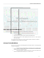
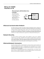
Ethernet Communication Network
The T6200 Controller uses IEEE 802.3 10Base-T Ethernet communication network. Ethernet uses
the Carrier Sense, Multiple Access, Collision Detect (CSMA/CD) datalink protocol, which employs a
broadcast method for communicating with nodes. When a station senses that the network is idle and
it is ready to send, it transmits its data packets to the network. Since all nodes hear the data, each
node checks to see if the packet is intended for it. The station that matches the destination address in
the packet is the one that responds. The collision detection part of CSMA/CD tells nodes to halt
transmission if a collision is detected and to try again later at a randomly determined delay period.
Network Security
The T6200 Controller incorporates automatic control redundancy to insure process equipment
operation in the event of failure. Redundant network components can further enhance overall system
security by maintaining communications in case of certain device malfunction and by allowing online
repair of faulty components. With proper redundancy implementation an Ethernet network can detect
when a particular path cannot pass data and then automatically switch to a backup path. Refer to
T6200 Equipment Selection and Planning Guide for more information on network security.
Ethernet Network Connectors
The T6200 Controller includes two individual IEEE 802.3 10Base-T Ethernet connections (ENET1 and
ENET2) with standard RJ-45 connectors to facilitate control network communication. Refer to Figure
3-8 (Integral Termination Panel), Figure 3-9 (Redundant Remote I/O Backplane) or Figure 3-10 (NonRedundant Dual Remote I/O Backplane) for connector location and Figure 3-12 for Ethernet ENET1
and ENET2 connector pin assignments.
Note on Figure 3-10 (Non-Redundant Dual Remote I/O Backplane) ENET1 on the Primary Control
Board is referenced as ENET1P and ENET2 is referenced as ENET2P. ENET1 on the Second Control
Board is referenced as ENET1S and ENET2 is referenced as ENET2S.
3-19
Hardware Installation/Maintenance
FIGURE 3-12
Ethernet
ENET1 and ENET2
Connector
Pin Assignments
Pin
1
2
3
4
5
6
7
8
Signal
TXD+
TXDRXD+
NC
NC
RXDNC
NC
Pin 1
Pin 8
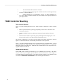
Network Cabling
Ethernet is used as the high-speed wire media to provide the control network communication
capabilities for the T6200 Controller systems. Typically, the control network is an isolated Ethernet
network that provides communication between the T6200 Controller and workstations. It uses
Ethernet hubs and/or switches for communication connections.
Use Ethernet category five (Cat 5) cables for the Ethernet network cables. The maximum cable
length from the T6200 Controller to the hub/switch is 10 ft. (3 m). The maximum cable length from
the hub/switch to any other node is 330 ft. (100 m) for longer distances, fiber optic cables are
required.
Non-Redundant Network
The basic simplex network consists of a hub and Cat 5 cables that connect to each node. The T6200
Controllers have redundant Ethernet ports as a standard feature (whether they contain simplex or
redundant control boards). When installing a simplex network, using Ethernet 2 port is optional.
Refer to Figure 3-13 for a single T6200 Controller and Figure 3-14 for multiple T6200 Controllers.
FIGURE 3-13
Non-Redundant
Network with
Single T6200
Controller and
Single
Workstation
3-20
Hardware Installation/Maintenance
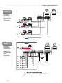
FIGURE 3-14
Non-Redundant
Network with
Multiple T6200
Controllers and
Dual
Workstations
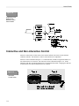
Redundant Network
Network redundancy for communication security is provided by a secondary hub and cables that
establish a secondary network identical to the primary network. The secondary network is connected
to the redundant communications port of each workstation and Controller, and is connected to a
separate hub/switch. Refer to Figure 3-15.
FIGURE 3-15
Redundant
Network with
Single T6200
Controller and
Redundant
Workstations
3-21
Hardware Installation/Maintenance
FIGURE 3-16
Redundant
Network with
Multiple T6200
Controllers and
Redundant
Workstations
FIGURE 3-17
Redundant
Network with
Multiple T6200
Controllers
Mounted in a
T6200R Subrack
and
Redundant
Workstations
3-22
Hardware Installation/Maintenance
FIGURE 3-18
Non-Redundant
Network with
Single Dual T6200
Controller and
Single
Workstation
FIGURE 3-19
Redundant
Network with
Multiple
Dual T6200
Controller and
Redundant
Workstations
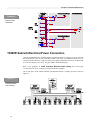
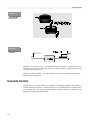
T6200R Subrack Ethernet
The Ethernet Hubs on the T6200R Subrack are usually connected as shown in Figure 3-17.
If the workstation is not part of an existing network, connect the workstation to port eight on the
hubs. Set the Up-Link switch to “Normal”.
To connect the hubs to an existing network; set the Up-Link switch to “Up-Link” and connect
existing network to port eight.
The Operator Interface is usually connected to port seven on Ethernet 1 Hub.
3-23
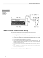
Hardware Installation/Maintenance
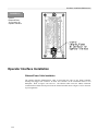
FIGURE 3-20
Internal
Ethernet/Power
J6 Connector for
Operator Interface
Operator Interface Installation
Ethernet/Power Cable Installation
The Operator Interface Ethernet/Power cable is routed thru the center of the T6200 Controller
housing and plugged into connector J6 inside the Controller on the Termination Panel or I/O
Backplane. Refer to Figures 3-20 and 3-21. The Ethernet cable carries the 10Base-T Ethernet
communications and the 26Vdc power from the T6200 Controller. Refer to Figure 3-22 for connector
J6 pin assignments.
3-24
Hardware Installation/Maintenance
FIGURE 3-21
Operator Interface
Internal
Ethernet/Power
Cable
Installation
FIGURE 3-22
Operator
Interface J6
Connector Pin
Assignments
Pin
1
2
3
4
5
6
7
8
Signal
TXD+
TXDRXD+
+26V PRI
+26V SEC
RXDCOM
COM
Pin 1
Pin 8
Operator Interface Attachment to T6200 Chassis
The Operator Interface is attached to the T6200 Chassis by four screw collars.
The Operator Interface is installed by placing the two top screw collar slots at the rear of the case
over the two top screw collars. The case should be angled slightly out at the bottom. Once the top
screw collars align thru the top screw collar slots, the case can be straightened vertically and then
slide down until it stops on the case slots edge. Refer to Figure 3-23.
The Operator Interface may be removed by pulling the Latch Release Pull located at the bottom right
of the case at the same time sliding the case up then away from the T6200 Chassis.
FIGURE 3-23
Operator Interface
Attachment to
T6200 Chassis
3-25
Hardware Installation/Maintenance
Standalone T6200 Controller Operator Interface Ethernet
External Cable Connection
For Standalone T6200 Controller applications where no communications to other controllers or
workstations are required, the T6200 Controller ENET1 connector may be connected directly to the
OI (Operator Interface) connector with a short Ethernet crossover cable (ICS Triplex p/n 6009-0030)
eliminating the necessity of an Ethernet hub. Refer to Figure 3-24.
FIGURE 3-24
Standalone
T6200 Controller
Operator Interface
Ethernet Crossover
External Cable
Connection
3-26
Hardware Installation/Maintenance
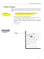
Firmware Changes
Firmware is the software, operating system, and function library that has been programmed into an
EPROM (erasable programmable read-only memory). Should it become necessary to update the
firmware or install a custom firmware in the field, the EPROM will have to be replace. To change the
EPROM:
The Controller contains parts susceptible to damage by electrostatic discharge.
Normal precautions should be taken to avoid high static voltages.
CAUTION
Carefully slide the control board out the front of the chassis.
Use an Amp 44 pin PLCC extraction tool number 82159-1 to remove the EPROM from the
socket. The EPROM is the 44 pin IC with a label. Refer to Figure 3-25.
Install the new EPROM. The EPROM is keyed with a notch on one corner. This notch must
be in the same orientation as the notch on the EPROM socket while plugging the EPROM into
the socket.
Replace the control board.
Load configuration.
FIGURE 3-25
T6200 EPROM
Placement
3-27
Hardware Installation/Maintenance
Serial Communication Connection
The T6200 includes two individual RS-232/RS-485 serial port connections (COMM 1 and COMM 2)
with RJ-45 connectors to facilitate serial communication. COMM 1 and COMM 2 are software
configurable for either RS-232 or RS-485. See Appendix C Modbus Interface RS-232 for COMM
1 and COMM 2 RS-232/RS-485 Configuration. Note: RS-485 is not multidrop. Refer to Figure 3-8,
Figure 3-9, or Figure 3-10 for appropriate COMM 1 and COMM 2 connector location. Note: NonRedundant Dual Remote I/O Backplane (Figure 3-10) has only COMM 1 for the Primary and Second
Control Board. Refer to Figure 3-26 for COMM 1 and COMM 2 connector pin assignments.
FIGURE 3-26
Serial
Communication
Connector
3-28
Pin
1
2
3
4
5
6
7
8
Signal
NC
NC
TD (RS-232)/COMM-(RS-485)
SG (SIGNAL GND)/COM
SG (SIGNAL GND)/COM
RD (RS-232)/COMM+ (RS-485)
NC
NC
Pin 1
Pin 8
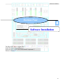
Software Installation
Section Four
4
Software Installation
The Micon OPC Server Compact Disc 2
Install The Packet Driver Software 2
Install the MICON OPC Server and Related Components 5
Ethernet Addresses 7
4-1
Software Installation
Software Installation
Instructions for the installation of the MICON OPC Server and a sample OPC Client software on
Microsoft Windows XP.
The Micon OPC Server Compact Disc
The MICON OPC compact disc contains the Micon OPC Server, a sample OPC Cliente. The setup
program for the MICON OPC Server software and the sample OPC Client software are located in the
“MICON” folder. Create a directory "C:\MICON" on the installation computer. Note that the "MICON"
folder must be in the root directory of the "C" drive.
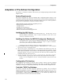
IMPORTANT NOTE: If you plan to use the IEC-61131 based graphical configurator from MICON
called “Straton for MICON”, then you MUST install that package before installing the MICON OPC
Server.
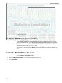
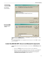
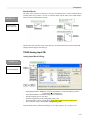
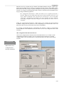
Install The Packet Driver Software
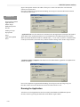
Open the Network Connections window:
4-2
Right-click “My Network Places” icon, located on the desktop (Figure 4-1)
Select “Properties”
Software Installation
Figure 4-.1
Desktop Window
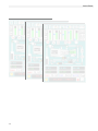
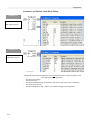
Open the “Local Area Connection Properties” window:
Right-click “Local Area Connection” (Figure 4-2)
Select “Properties”
Figure 4-2
Network Connections
Window
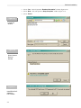
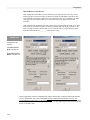
Open the “Select Network Component Type” window:
Select “Install…” (Figure 4-3)
Open the “Select Network Protocol” window:
Select “Protocol” (Figure 4-4)
Select “Add…”
Open the “Install From Disk” window:
Select “Have Disk…” (Figure 4-5)
4-3
Software Installation
Figure 4-3
Local Area
Connection
Properties Window
Figure 4-4
Select Network
Component
Type Window
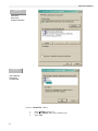
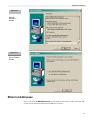
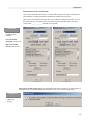
Open the “Locate File” window:
4-4
Select “Browse” (Figure 4-6)
Locate the "\ndisnt” folder on the installation CD
Select “OK”
Software Installation
Figure 4-5
Select Network
Protocol Window
Figure 4-6
Install From Disk
Window
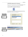
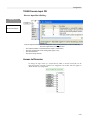
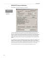
Windows will select “OEMSETUP.INF” in the “File name:” field as shown in Figure 4-7. Select
“Open” to install the NDIS3P2K.INF driver.
The “Virtual Packet Driver” will be highlighted as shown in Figure 4-8. Select “OK” to complete
the driver installation.
Install the MICON OPC Server and Related Components
Install the MICON OPC Server and related components. Execute the file "\MICON\Setup.exe” on
the CD:
Double click “MICON” folder located in the root directory of the CDROM drive
Double click “Setup.exe”. The setup program will copy various files to your hard disk drive
and copy the OPC Server and related files to a directory of your choice. Then the setup
program will proceed to install the OPC Data Access components. This will open the
“InstallShield Self-extracting EXE” window (Figure 4-9).
4-5
Software Installation
Figure 4-7
Locate File
Window
Figure 4-8
Select Network
Protocol
Window
Figure 4-9
InstallShield Selfextracting
EXE Window
4-6
Select “Yes”. This will open the “Readme Information” window (Figure 4-10).
Select “Next”. This will open the “Setup Complete” window (Figure 4-11).
Select “Finish”
Software Installation
Figure 4-10
Readme
Information
Window
Figure 4-11
Setup Complete
Window
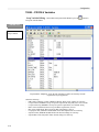
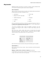
Ethernet Addresses
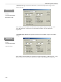
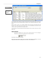
Edit or create a file "C:\MICON\devlist.txt" using Notepad or some other text editor. In this file, add
one line for each T6200 Controller's Ethernet addresses as follows:
4-7
Software Installation
Primary Control Board Ethernet Address
Backup Control Board Ethernet Address
UC254,00:08:9A:D2:05:02,00:0D:9A:D2:05:02,
UC255,00:08:9A:D2:06:02,00:0D:9A:D2:06:02,
BAK ID from I/O Backplane
PRI ID from I/O Backplane
T6200 Controller Name
The strings are separated by a comma. The first string is the name for the T6200 Controller. The
second string is the Ethernet address for the primary control board and the third string is the Ethernet
address for the backup. Make sure there is a comma at the end of each line. There can be only one
Controller per line. Refer to Figure 4-12. The Controller/s listed in this file will be the only one/s that
the MICON OPC Server will communicate with at runtime.
Figure 4-12
devlist.txt – Notepad
Window
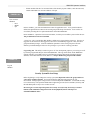
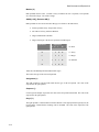
The T6200 Controller name must be a unique name and should have from one to 16 alphanumeric, dash (), and/or underscore (_) characters. The name cannot contain spaces (blanks) or other symbols. The first
character of a name cannot be a dash or number. Both upper and lower case letters are accepted.
The PRI ID and BAK ID numbers on the T6200 Controller I/O Backplane is used to build the Ethernet
addresses. Refer to Figure 4-13. Add “00:” in front of each number, add “:” between every other digit,
and add “:02,” to the end.
Figure 4-13
T6200 PRI ID and
BAK ID
4-8
T6200 Controller Operation
5
Section Five
T6200 Controller Operation
Push to Activate Switch 5
System Start-up 6
Replacing Control Boards 6
Loading Controller Configuration 8
Watchdog Timer 8
5-1
T6200 Controller Operation
5-2
T6200 Controller Operation
T6200 Controller Operation
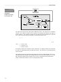
The redundant T6200 Controller consists of two identical control boards, primary and backup, and one
termination panel. Refer to Figure 5-1. The primary control board is always on the left and the backup
is always on the right. Normally, the primary board is the active board and the backup board is the
standby board. These roles may be reversed. When the backup board is active, it transmits a “Backup
Active” alarm to the host.
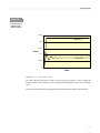
The active board controls both the analog and discrete outputs to the field. The analog and discrete
outputs are disabled on the standby board. Refer to Figure 5-2. When the outputs are required to
feedback as inputs, the outputs of the active board are used in both boards. A primary board without a
backup is always active. The active and standby boards have the same inputs and configuration.
Push to Activate Switch
A PUSH TO ACTIVATE switch (SW1) is located at the front of each control board at the bottom.
Refer to Figure 5-3. The switch has three functions:
Used to activate a standby Controller. The NORMAL LED must be illuminated before
this Controller can be activated. If the Controller is activated, the redundant Controller will be
deactivated automatically.
This switch can also be used to clear all the configuration in the Controller memory.
This can be accomplished only during the first three seconds when the Controller is being
powered up by depressing the switch for one second or more.
Each time this switch is depressed, the Controller identification number will be
transmitted to the host over the Ethernet communications. This may be used when adding a
Controller to the network.
5-3
T6200 Controller Operation
FIGURE 5-1
T6200 Primary
and Backup
Control Boards
Figure 5-2
T6200-C Active
and Standby
Current Outputs
System Start-up
When power is first applied, the T6200 Controller forces the analog outputs to zero and the discrete
outputs to open. Next, the T6200 Controller starts the self-test and flashes the COMM LEDs. After the
self-test has been successfully completed, the primary board will become active. The OUT LED will
illuminate on the backup board during this wait period. There must be a board in the primary position
when running the Controller Definition program in A/S VIEW. If the T6200 Controller does not have a
primary board when power is first applied the backup board outputs will remain in their power-up reset
condition.
5-4
T6200 Controller Operation
TABLE 5-1
Control
Board LEDs
LED
NAME
COLOR
DESCRIPTION
ACT
(TOP)
Active
Green
NOR
Normal
Green
EN1
Ethernet 1
Yellow
EN2
Ethernet 2
Yellow
COMM1
Communication 1
Green
COMM2
Communication 2
Green
OUT
Outputs
Red
This LED shows the Active/Standby status
of the Controller. When illuminated, the
Controller is “Active” and controls the
outputs. When a backup Controller is
used, either primary or backup can be
active, but not both of them.
The LED shows the status of the watchdog
timer. The LED is illuminated when the
microprocessor is properly toggling the
watchdog timer.
This LED will flash when data is being
transmitted or received on Ethernet 1
This LED will flash when data is being
transmitted or received on Ethernet 2
This LED will flash when data is being
transmitted or received on COMM 1 or
backup communication
This LED will flash when data is being
transmitted or received on COMM 2
This LED illuminates when the outputs are
inhibited. This condition normally occurs
during power up. The backup control
board cannot be active if this LED is
illuminated.
Figure 5-3
Push to
Activate Switch
Backup
Control Board
Primary
Control Board
“Push to Activate”
Switch
If the primary board has a configuration in its memory, it will start the loop processing. If the primary
boards do not have configuration, the outputs will remain in their power-up reset condition.
At startup, the backup board's memory is always cleared, and the primary board transfers the configuration
to the backup board through the backup serial link.
During runtime operation, if a new configuration is downloaded, it automatically goes to the active board.
If the active board is the primary board, the backup board's memory is cleared, and the primary board
5-5
T6200 Controller Operation
transfers the configuration to the backup board through the backup serial link. The standby primary
board’s memory cannot be cleared during runtime operation without removing the board. To transfer a
configuration from a backup board to a primary board, the primary board must be removed (unplugged)
and reinstalled, clearing the memory at the same time (see Replacing Control Boards below). The
primary board, with cleared memory, will then request a configuration transfer from the active backup
board.
Replacing Control Boards
In a system with redundant boards, the backup board can be activated to allow removal of the primary
board without upsetting the system. Depressing the PUSH TO ACTIVATE switch will activate the
backup board. The NORmal LED must be illuminated and the OUT LED must not be illuminated before
the board can be activated. When the backup board is active, it transmits a "Backup Active" alarm to the
host on the Ethernet. This alarm cannot be cleared as long as the backup board is active.
After the backup board has been activated, the primary board may be removed by pulling on the handle on
the front of the board to unplug it.
The memory must be cleared in the replacement board. To clear the memory, plug in the replacement
board and depress the PUSH TO ACTIVATE switch for one or more seconds within the first three
seconds. The OUT LED will illuminate for a few seconds while it gets the configuration from the backup
board and then compiles it. After the OUT LED goes off, depress the PUSH TO ACTIVATE switch to
activate the primary board.
If you do not clear the memory, the replacement board will retain its old configuration.
CAUTION
Before plugging in a replacement Controller, verify
it is the same model and the jumper placements are the same.
Refer to the jumper placement in Section Three,
Hardware Installation/Maintenance.
Each Controller model has a different mechanical key to prevent the incorrect model from being plugged
into the termination panel.
Plug in the replacement Controller. The NORmal LED will not illuminate for a few seconds while it gets
the configuration from the Backup Controller and then compiles it. After the NORmal LED illuminates,
depress the PUSH TO ACTIVATE switch to activate the Primary Controller.
When replacing a Controller that does not have a backup and the application process is shutdown, the
Controller can just be unplugged and the matching replacement board plugged in its place. If the
replacement board has an undesirable configuration, it can be cleared by depressing the PUSH TO
ACTIVATE switch for more than one second within the first three seconds after the Controller has been
plugged in. A new configuration can be down loaded from the host.
Loading Controller Configuration
If a Controller is unplugged or power is removed long enough for the capacitor (that is used to keep the
RAM alive) to discharge (usually about one week) the above process will have to be repeated.
5-6
T6200 Controller Operation
Watchdog Timer
The microprocessor toggles the watchdog timer at least once every 100 milliseconds. If the watchdog
timer is not toggled within this time period, the watchdog timer will reset the microprocessor. If the board
is on standby, the outputs will be disabled. If the board is active, control will be transferred to the backup
board. If there is no backup board or if the OUT LED is illuminated, the outputs will remain at the
condition before the watchdog timer reset the microprocessor.
If the microprocessor does not start after being reset, the watchdog timer will continue to reset the
microprocessor every 1.6 seconds. If the microprocessor does restart in a redundant system, the board will
remain in the standby mode. If there is no backup board, the primary board will resume the active mode.
5-7
T6200 Controller Operation
5-8
HMI-6200 Operator Interface
Section Six
6
HMI-6200
Operator Interface
Preface 2
Overview of HMI-6200 Features 3
Event Information Processing 5
Display Layout 11
General Display Description 14
Graphic Displays Configuration 17
HMI Example – Single Stage Compressor 18
Adaptation of Pre-Defined Displays 21
Surge Curve Screens 25
Custom Graphic Screens - 26
Configuring the Security System 27
Communications 30
Downloading the Updated Application 34
6-1
HMI-6200 Operator Interface
HMI-6200
OPERATOR INTERFACE
Preface
To be effective in a small (5.7” P/PC size) footprint, the operator interface must be ergonomically
pleasing and comfortable to the user. While this may seem to be a fairly easy goal to achieve with
today's well accepted Menu Bar interfaces, a number of elements come into play with a process
controller-based environment that must be brought into proper relationship with the operator-elements
such as instant alarm access, prevention of accidental value entry, value setting accuracy, etc.
The HMI-6200 display architecture is flexible, yet clean and simple in appearance and interacts with
every application in the same manner. The windows, menus, etc. are consistent looking and behaving.
The prompting and pre-formatted type display hides the complex window access procedure and
simplifies operation to a point where a virtually untrained person can easily navigate between displays.
It provides an intuitive means of interacting with the process.
The touch screen provides for simple operator interaction. Direct touch or a pen (stylus) are used for
contact with the screen.
For lager size touch panel computers (12.1, 15 ..etc inch screen size) several displays can be grouped
on each screen. The screen grouping is accomplished by right-clicking the Group Screen on the Screen
menu of the WEB Studio software.
6-2
HMI-6200 Operator Interface
Overview of HMI-6200 Features
A standard option of the T6200 Unit Automation System is to incorporate an integral 5.7 inch P/PC
based full-featured human-machine interface – HMI-6200.
This Operator and Engineering Interface Software offers…
- Standard and Customized Screens
- On-Line Operation and Control
- On-Line and Remote Diagnostics
- Alarm and Event Management
- Critical Event Archiving
- Trend and Historian
- OPC Compliant Client-Server Architecture
- Unit Asset Condition Management - UAM
HMI-6200 Microcontroller –
- Intel StrongARM SA1110 microprocessor
- 32 MB Flash Memory
- 64 MB SDRAM Memory
- Integrated LCD controller
- Ethernet connectivity
- CompactFlash slot
- Card Speaker
Database Management –
Object oriented database
- Fill-in-the-blank definitions
- Data accessible system wide
Standard Environment –
Based on Microsoft’s DNA architecture
- Industry standard operating system – Windows CE
- Distributed COM
- XML technology
True Multi-User Capabilities –
- Supports multiple P/PC’s and workstations
- Networkable on popular local and wide area nets
- Web enabled to serve HTML pages over the Web with
real-time data
- Allows sub-division of process responsibilities to different users
Business Interoperation –
Unit control can be integrated into a total plant/business system.
- Integrates TMC Unit Control and Business Asset technology
- Imports and exports real-time data and reports in XML
- Protected data ownership and security
6-3
HMI-6200 Operator Interface
OPC Client/Server –
The build-in CE OPC Server is compatible with the StrongARM processor
Enables communication with control modules
- Open systems OPC link
- Server identifier
- Configurable data update rate
If an operator interface other than the HMI 6200 is selected
make sure that the OPC server is compatible with its processor.
Comprehensive GUI –
Based on WEB Studio, the graphical user interface offers object oriented easy to use graphics.
User-defined and pre-defined graphic displays. Used to monitor and control a TMC process.
- Pre-defined displays include:
Home; Graphics, Face-Plates; AIN/AO; DIN/DO; Alarm Summary, Alert Summary; Trend;
Historical Trend;
- Scripting language including math expressions, statistic and logical functions, module activation
functions, etc.
- Build hierarchies and networks of displays
- Displays real-time & historical data
- Translation Tool for multi-language operation
Time-Scheduled Tasks –
Provides time-based user defined operations
- Event types: Reports, Recipes, Calculations, data logs, match/logic functions or any program
- Scheduling intervals from seconds to years
- Quickly defined and interactive
- Schedules application programs
Alarms and Alerts Processing –
Provides comprehensive alarm reporting
- SOE (sequence of events) capabilities
- Individual or multiple alarm acknowledgements
- Remote Ack (acknowledge)
- User definable priorities
- User definable status colors (start, ack, norm)
- Archive storage and call back
Real-Time and Historical Trending –
All data base points may be selected for trending
- Selectable plot scales, time spans, colors, grid sizes
- Up to 8 plots per window
- Selectable curve type (X/t, X-Y)
- Save On Trigger or Save on Tag Change selection
- Archive storage and call back
Recipes and Reports –
Facilitates assessment of unit performance
- Easy creation of reports (without programming tool)
- Load recipes and retrieve values in XML format
6-4
HMI-6200 Operator Interface
Event Information Processing
The following describes the information structure for alarm and alert handling and for trend and
historical recording
Alarm and Alert Definition –
The T6200 includes comprehensive detection and notification of alarms and alerts. Alarms are defined
as conditions which require user acknowledgement; alerts are records of actions/conditions for which
operator acknowledgement may or may not be specified (Ack is configuration selectable).
Alarm and Alert Detection –
For reliability and speed-of-response alarm and alert detection and processing takes place in the control
module of the T6200. All alarms and alerts are time-stamped upon detection.
Deterministic Alarming –
Deterministic alarms/alerts are generated by comparing the performance of combinations of discretes
and/or variables against pre-defined limits of alarmable conditions of operations. Practically unlimited
logic/math/selection functions are provided in the control module of the T6200 to allow for simple or
sophisticated alarm/alert interlocking.
Deterministic alarm configurations serve basically two purposes - 1) they can be used to advise or take
action based on the nature of alarm combinations or 2) deterministic alarming can also be used to
disregard alarms/events that are merely further effects of a fault that has already been recognized. Two
examples of combinational alarms would be:
- Do not generate a low flow alarm if a corresponding pump is turned off.
- Alarm on deviation of a process signal from a trip-point only if the rate of change or another variable
exceeds specification at the same time that certain valves are fully open and a feed pump is off.
Alarm and Alert Suppression –
Alarm and alert processing can be suppressed at the control module level. The configured suppression
may be for specific alarm/alert points or groups and is normally process condition related. Notification
of suppression is provided via alarm “cutout” attributes.
Alarm and Alert Notification –
The HMI-6200 (operation interface) provides several features for notification of alerts and alarms.
These include: HMI display, audible annunciation and optional control triggering.
6-5
HMI-6200 Operator Interface
FIGURE 6-2
Alerts - Summary
Display
Historical Alarm and Alert Display The Alarm/Alert History display provides for means of viewing past Alarm and Alert events. Historical
data can be retrieved with convenient date/time selection buttons.
FIGURE 6-3
Alarms - History
Display
6-6
HMI-6200 Operator Interface
Dynamic Trending Module –
The HMI-6200 trend capability provides for viewing of real-time and historical data. A trend display
format, with up to six plots, is included.
Trend Configuration –
The contents of the Trend and the Trend History display are defined by trend window templates as
shown below.
FIGURE 6-4
Trend History
Definition
Windows
FIGURE 6-5
Trend Points
Configuration
Window
Compressor App
6-7
HMI-6200 Operator Interface
6-8
HMI-6200 Operator Interface
Trend Display –
The trend display is presented in the popular strip chart recorder format.
FIGURE 6-6
On-Line Trend
Display
Historical Tend Display The Trend History display provides for a comprehensive means of viewing process and calculated data
over periods of time. Historical data can be retrieved with convenient date/time selection buttons
6-9
HMI-6200 Operator Interface
FIGURE 6-7
Trend History
Date/Time Selection
6-10
HMI-6200 Operator Interface
Display Layout
Preformatted displays provide the basic operations interface for: compressor/turbine control, continuous
process control, batch/sequence control, SCADA alarms, trends, etc. Information is presented in an
easily understood manner.
The operational displays are organized into a structural hierarchy consisting of overview(s), graphics,
face-plates, etc. Displays are called up through a simple menu bar procedure. In addition to the menus,
the user is provided with “go-to” display buttons to allow for customized window selection.
Besides the configuration at the time the systems is set up, some configuration is normally done later
on, such as building additional graphics.
Analysis of process conditions is fully supported. A standard trend display (real-time and historian
trend), alarm and alert indication (real-time and historical) and diagnostic displays allow for quick
process analysis and situation correction.
Reports and Recipe screens and the ability to retrieve values in XML format facilitate the assessment
and correlation of unit performance.
FIGURE 6-8
Operational
Display
Hierarchy -
T6200
Unit Controller
Overview
MICO
HOME
N
U-200
T6200
Unit Controller
Graphics
Face-Plates
GRAPHIC
MICO
NU-200
#1
T6200
Unit Controller
ALARM
MICO
ALERT
NU-200
SUMM
T6200
Unit Controller
GRAPHIC
MICO
NU-200
#2
T6200
Unit Controller
T6200
Unit Controller
T6200
Unit Controller
TREN
MICO
D
NU-200
HIST
OPER
MICO
NU-200
STATUS
PROC
MICO
NU-200
STATUS
T6200
Unit Controller
T6200
Unit Controller
MICO
GRAPHIC
NU-200
#N
T6200
Unit Controller
T6200
Unit Controller
T6200
Unit Controller
FACE-PL
MICO
NU-200
#1
FACE-PL
MICO
NU-200
#2
FACE-PL
MICO
NU-200
#N
Operation/Process Displays
DIAGN
MICO
FLOW
N
U-200
CHARTS
T6200
Unit Controller
LOOP
MICO
NU-200
TUNING
T6200
Unit Controller
I-LOCK
MICO
NU-200
ESD
T6200
Unit Controller
T6200
Unit Controller
DIAGN
MICO
FLOW
N
U-200
CHARTS
DIAGN
MICO
FLOW
N
U-200
CHARTS
T6200
Unit Controller
REPORT
MICO
NU-200
RECIPE
T6200
Unit Controller
AUX
MICO
GRAPHIC
NU-200
#1 -- #N
Status/Diagnostic/Aux displays
The HMI-6200 is designed to facilitate operation at all levels. It allows simplified access to the
controls, provides a logical display format, and incorporates methods for easy interaction with the
process. Operation and management may call up displays from many different unit areas for a concise
picture of unit and plant/pipeline performance.
The HMI-6200 also supports engineering functions in the creation and scheduling of reports and
recipes.
Status displays, diagnostic flow charts, tuning indication and other user-defined auxiliary displays
enable rapid situation correction.
6-11
HMI-6200 Operator Interface
HMI-6200 Header and Footer Template
The Web Studio screen editor allows you to create a variety of windows and dialogs which feature user
inputs by screen selection and touch pad. The following relates to the HMI-6200’s process display
access formats that are pre-defined by a standard Header and Footer template.
FIGURE 6-1
Graphic display of
a Column with
Top and Bottom
Reflux
Pre-defined
Header and Footer
template described
below
Header
-
Next (f) and Last (e)
Home display access
Graphic display(s) access
Face-Plate display access
Trend/Historian display access
*** Miscellaneous display access
Footer
6-12
HMI-6200 Operator Interface
- UAM displays access
- Alarm Summary/History display access
- Alert Summary/History display access
6-13
HMI-6200 Operator Interface
General Display Description
“Home” Display –
The “Home” display typically provides for an overview presentation of the compressor performance
with an “at a glance” identification of off-normal and alarm conditions. The operator can select directly
subdisplays (Graphics, Face-Plates, Diagnostics and Operation etc.) from this display to bring details
into view.
Graphic Display(s) –
While pre-defined custom graphic displays meet the need of most users, many still may wish to create
additional displays that are specific to their respective TMC operations.
The displays normally consist of graphical symbols, bar-graphs and alphanumeric information. They
represent real-time database information graphically and allow for user-specific actions and control. From
the graphic display(s) the operator can also directly select sub-displays (Face-Plates, Operation and
Process Status, Diagnostics, etc.).
Face-Plate Displays –
These displays show PID “face-plates” and process control parameters associated with the displayed
loops – Anti-Surge, Incipient Surge, Capacity, Load Share, I/O Overview.
Direct go-to buttons to displays of Operation Status, Diagnostics, Interlocks, Tuning are provided.
Alarm Summary Display –
The alarm summary display identifies and summarizes all new alarm points along with other
acknowledged alarm points. It lists time of occurrence and description. The display shows 16 alarms
per page. A scroll-bar is used to access all alarms.
Alarm priority and filter as well as the message color are defined during configuration (creation of the
alarm worksheet).
The Alarm History display allows for dissemination/ diagnostics of historical alarm conditions. This
display includes convenient date and time selection.
Alert Summary Display –
In order to provide segregation between alarms and alerts/events a separate alerts group is included.
Operation and function of this display is identical to the alarm summary display.
6-14
HMI-6200 Operator Interface
Trend Display –
The trend module displays analog and discrete points on trend of any tagged system variable. The trend
display can contain up to six variables (plots) – continuously updated. Plot colors, scale (Min, Max),
Cursor Value and time span are selectable. Curve type can either be X/t or XY.
One can store the trend points in a history file for data collection and display. The historian module
includes a dead band (for data storage reduction) and incorporates save on Trigger or Tag Change
selection. The Trend History display also contains time and date selection.
Miscellaneous Displays Operation and Process Status Displays –
Operation indication is structured to quickly and accurately determine process status and to allow for
fast response.
Diagnostic Displays –
The unit maintenance functions can be supported by diagnostic displays which provide the user with a
flow-chart type view of the control loops.
Analog and Discrete I/O Displays –
The I/O displays provide a summary of the analog and discrete point values. Each rectangle includes
the abbreviated point name and the value.
Equipment Condition Displays –
Condition display(s) can be provided to illustrate status (Interlock, ESD status, etc.) and pertinent values
of the process equipment.
Detail Display(s)
Displays for calculation and fall-back value settings are typically included to provide an overview of
key parameters.
Reports and Recipes –
Reports can be created without needing any special programming tool (like VB, etc.). Using the report
workstheet and the scheduler, reports can be custom designed and scheduled for display and
transmission.
The recipes module (worksheet) is used to create, load and delete recipes. Recipes, in this case, means a
group of tags that have their values saved and retrieved like a database. The values can be retrieved
from the ASCII file in standard format or the XML format.
6-15
HMI-6200 Operator Interface
FIGURE 6-9
Workspace Window
Task Tab
Scheduler –
Critical and control related timed-tasks normally reside in the T6200 control module(s). However,
timed tasks for reports, supervisory recipes, trend and math are typically handled by the HMI-6200
Scheduler module.
The timed-task module (scheduler) supports reports, logs, recipes and general actions (math and logic
functions). It provides for the scheduling, definition and detection of timed tasks. The tasks may be
scheduled to execute automatically once, or any number of times at fixed intervals as pre-defined by the
user.
The Clock event is used to trigger actions based on regular time intervals such as timers and counters.
The base time (minimum of 100 ms) is set in the Time column. In the Tag column, one must configure
the tag that will receive the result from the expression configured in the Expression column. The
Disable field can be used to prevent an expression in the line from being executed.
The Calendar event is used to trigger actions on a scheduled time. Also, it is possible to specify a fixed
date for an event in the Date column.
The Change event is used to trigger an action upon a change in tag value (such as special trend on incipon). In the Trigger column, one must configure a tag that will be used to trigger the event when the
change in value has occurred.
FIGURE 6-10
Scheduler
Configuration
Example for IncipInitiated Trending
6-16
HMI-6200 Operator Interface
Graphic Displays Configuration
The HMI-6200 graphics software is a runtime-only version of the workstation PC graphics. All
configurations of graphic displays are made using a workstation PC and then downloaded to the HMI6200 P/PC Operator Interface. Once in run-time mode, the user is able to execute all runtime functional
dynamics that have been added/defined during configuration.
Powerful HMI Visualization A complete set of drawing and animation tools is furnished. One can create graphic objects and build
displays using any combination of drawing tools (boxes, lines, circles, text, etc.); save the graphic
objects in a library, add expressions and animation.
Dynamic Object Animation –
Considering the small (P/PC size operator interface) footprint, it is important to provide highperformance animation effects based on dynamic real-time links. The dynamic action tool offers
rotation, animation, analog color, flash, etc.
Summary of Graphic Features:
- High Performance Object-based Graphics
- Powerful Display Creation Tools
- Dynamic Animation
- Import Popular Display Formats
- Extensive Symbol Library
- Built-in Math, Expressions and Calculations
FIGURE 6-11
Graphics
Configuration
Screen
6-17
HMI-6200 Operator Interface
HMI Example – Single Stage Compressor
The following shows an example of a T6200 Compressor Unit HMI for single stage centrifugal
machines.
The HMI is designed to facilitate operation at all levels. It permits simplified access to the unit,
provides a logical display hierarchy, and a choice of navigation for easy interaction with the process.
FIGURE 6-12
Compressor Home
Screens display the
Performance Map
and process values
at “a glance”
FIGURE 6-13
Compressor Graphic
Screens provide for
visual overview and
for control
Graphic Overview Display/Control
6-18
HMI-6200 Operator Interface
FIGURE 6-14
Compressor FacePlate
Screens and Aux
Displays provide for
traditional operation
convenience
A/S Face-Plate Display/Control
Capacity Face-Plate Display/Control
LS Face-Plate Display/Control
LSE Face-Plate Display/Control
Lube Oil Display/Control
Seal Gas Display/Control
6-19
HMI-6200 Operator Interface
From operator displays to maintenance screens to engineering displays the HMI-6200 covers the full
interface spectrum. This color LCD display represents an HMI with full DCS/SCADA capabilities. It
provides a complete “window” on the process by which one can operate/control, maintain and manage
the process unit.
FIGURE 6-15
Compressor Driver
Display provides for
Turbine Status
Indication
Driver Status Display
FIGURE 6-16
Quench Control
Overload Control
Suction Control –
all on one display
Quench & Overload Face Plates
6-20
HMI-6200 Operator Interface
FIGURE 6-17
Maintenance Screens
facilitate process and
control diagnostics
Operation Status Display
Process Status Display
Load Share Diagnostic Display
Load Efficiency Diagnostic Display
Loop Tuning Display/Entry
Interlock Display
Adaptation of Pre-Defined Displays
The general HMI-6200 operator interface consists of preformatted displays. These displays are
structured into overview(s), graphics, face-plates, trend, etc. The user is provided with an operator
6-21
HMI-6200 Operator Interface
interface that allows for easy customization and adaptation to the specific process/plant configuration.
Besides adaptation at the time of system set-up, some display configuration is usually done later on.
System Requirements
The HMI-6200 operator interface is based on Web Studio. To develop/adapt an application with Web
Studio software, the following hardware and software is recommended for the Host computer...
- IBM-compatible computer with an Intel compatible processor
- Windows NT/XP/2000 operating system
- 128 MB of RAM
- 200 MB of free hard disk space
- MS Internet Explorer 4.0 or higher
- CD-ROM drive (only for initial setup)
- Ethernet connection for downloading applications
Installing Web Studio
The installation CD is used to install InduSoft Web Studio. The development environment runs on
Microsoft Windows NT/XP/2000; the CEView runtime environment, which is downloaded to the HMI6200 operator interface, comes pre-installed on the runtime workstation.
The Web Studio provides the tools needed to adapt the pre-formatted HMI-6200 operator interface to
the customer’s specific application. Refer to InduSoft Web Studio installation instructions.
Screen Editing and Configuration
The screen editor permits to change the pre-defined ICS TRIPLEX screens and create new screens and
dialogs. The configuration task allows for changing any element in the configuration, including the
database. An emulation of the revised/extended application can be run and tested on the development
computer before downloading it to the HMI-6200 operator interface.
Refer to the on-line Technical Reference and User Manual under the Help tab for detailed instructions.
Tag Database
The T6200 is delivered with a pre-configured Application Tag database. These tags are shown/declared
under the Tag List and Datasheet View of the Database tab.
The pre-configured Application Tag database consists of generic tags. It is recommended that this
generic tag structure be retained and that custom tag requirements be accommodated by simple labels
on faceplates, etc. (not database tag changes).
6-22
HMI-6200 Operator Interface
Class Tags
Loop tags – PV, SP, Out, Mode – are defined in a tag format called “classes”. This permits a high
degree of encapsulation. When a class-type tag is created, it does not contain a single value, but a set of
values associated with the loop. When a new loop is created, it is recommended to follow the predefined class type definition.
Database Exercise
In the development computer Workspace window, select the Database tab. Click the Application Tags
folder to expand it and double-click the Datasheet View line to open the database worksheet.
FIGURE 6-18
Workspace Window
Database Tab
selection of
Application Tags
Note that the database was updated during the development (tags appear as they are created and empty
spaces are present as a result of deletions).
For this database exercise example, we add/define a discharge temperature tag and associated alarm
tags. We need to configure the Application Datasheet as follows (in order to fill in the field, click on
the field after the last defined tag and type the data).
On line # 64…
Name: type
Td_a; Array Size: type 3 (four stage compressor, 0-3); Type: click ▼ and select Real; Description: type
Td Absolute (Deg R or K); Web Data: click ▼ and select Local or Server.
On line # 65…
Name: type
Td_FB; Array Size: type 3; Type: click ▼ and select Boolean; Description: type FALLBACK Disch
Temp; Web Data: click ▼ and select Local or Server.
Repeat the data entry on line # 66 as shown below, to define the high temp alarm.
FIGURE 6-19
Application
Datasheet
Analog Input
configuration
We have created an additional analog input with High and FB alarms; now expand the Tag List folder to
verify the database addition you have created. Note that during the screen development, when you type
in a nonexistent tag, Web Studio will prompt you to check if you desire to create a new tag (if you
accept, it will create a window which permits to create the tag).
6-23
HMI-6200 Operator Interface
Changing/Expanding Screens
Before changing and/or expanding screens, you should consider the pre-defined structure of the
application screens. For new screens, you can use existing screens (including the Standard screen),
saving it under different names. To update/change an existing screen, insert/change the objects in the
window between the header and footer. It is not recommended to change the header or footer
arrangement itself.
The standard header and footer was used as template for all application screens. The footer area
includes a single line alarm object that displays the latest active alarm. The individual objects that make
up graphics, faceplates, etc. on the application screens are taken from the pre-configured objects in the
Library.
Database Updates/Additions Recommendation:
For most applications there are no update or addition requirements of the pre-defined Tags that are
stored in the Application Database. Or in other words, the pre-defined generic Application Database
does not have to be changed in most cases; user tags are accommodated by tag labels (not database tags)
‘drawn’ with the screen editors’ A/N characters.
If updating/changing Application Tags is required, keep the following syntax rules in mind:
• Although the maximum Tag length is 32 characters, Tags should be as short as possible
(typically not exceeding 12 characters)
• Tags must begin with a letter. They can be composed of letters, numbers, and the underscore
character (_)
• The tag name must be different from the Web Studios’ reserved internal tag names and math
functions
• While tag names are NOT case sensitive, both uppercase and lowercase characters should be
used to make tag names more clear
Make sure that No DRAG is set before working with any screen (see screen, lower right-hand
corner DRAG status). Enable DRAG (strike Ctrl > D on keyboard) only if you need to move/reposition
objects on the screen.
6-24
HMI-6200 Operator Interface
Surge Curve Screens
FIGURE 6-20
Surge CurveOp Point Display:
X/Y Map
SLL Configuration
below
-
-
Surge Curve Configuration: The Surge Limit Line (SLL) is arranged in a lookup table format
with linear vector interpolation. Up to 20 points can be defined. The X points define the domain
input – Hp,sim. The Y points define the range (output) – Q2,sim.
Click on Edit Mode Enable check. Drag the surge points to the desired position or use the
Up/Down buttons to position the surge points.
6-25
HMI-6200 Operator Interface
Custom Graphic Screens
While the pre-defined operating displays that are provided with the HMI-6200 operator interface meet
the needs of some users, many still wish to create displays that are specific to their respective unit
operations. Like the pre-defined displays, user-defined graphic displays are constructed via the Web
Studio Object Toolbar and by importing symbols from the Library.
FIGURE 6-21
Overview Graphic
Stage Graphics
Screens:
Custom Graphics
generated from predefined examples
The Overview screen (on left hand side above) is customized to provide a key variable type graphical
representation of the actual multi-stage CO compressor application.
The Stage graphic screen (on right hand side above) is configured to show the individual compressor
stages. One graphic screen is provided for each stage.
Control of process equipment should be built into the graphic displays so that an operator can select
Loops, etc. and command the equipment associated with it. By providing users with graphical
illustrations of the equipment, control is simplified and easier to understand. It is however
recommended that several steps requiring confirmation and authorization of control be used to minimize
the chance of accidentally actuating equipment. Carefully consider the Object Properties (such as
Confirm and Password) and evaluate if Security (see Configuration of the Security System) should be
enabled for the screen and/or specific control variables/points.
6-26
HMI-6200 Operator Interface
Configuring the Security System
The Security folder allows you to define Groups and Users as well as their access privileges to Web
Studio tools and to the application. Through the Database tab, you can tailor Groups and Users to your
security needs.
FIGURE 6-22
Workspace Window
Task Tab
Selection of
Security
- Password: __________ is pre-defined as the Main Password. You will need to enter the password
each time you access the Security System (so it is mandatory that your remember it). To change the
Main Password contact the factory.
- Development Group: Double-click Development, enter the Password, and the Group Account
window will open.
FIGURE 6-23
Security
Group Account
Window
Development Group
In this window, you enable/disable the Development Group operations and you set the range levels.
Verify that the Security Levels and Access are defined in accordance with your application
requirements.
6-27
HMI-6200 Operator Interface
- Maintenance Group: Double-click Maintenance, enter the Password, and the Group Account
window will open.
FIGURE 6-24
Security
Group Account Window
Maintenance Group
In this window you enable/disable the Maintenance Group operations and you set the range levels.
Verify that the Security Levels and Access are defined in accordance with your application
requirements.
- Operations Group: Double-click Operations, enter the Password, and the Group Account window
will open.
FIGURE 6-25
Security
Group Account Window
Operations Group
In this window you enable/disable the Operations Group operations and you set the range levels. Verify
that the Security Levels and Access are defined in accordance with your application requirements.
6-28
HMI-6200 Operator Interface
-
Users: Double-click the User Account labels of the Security System window, enter the Password,
and the individual User Account windows will open.
FIGURE 6-26
User Account
Windows
- Dev1
- Maint1
- Op1
In these windows, you create and maintain accounts for application users. Verify (and if needed redefine) the application users that will be in each group in the Group Account list. Users can also be
accessed by selecting the User option under Insert on the Main Menu Bar.
Password Button – Opens the User Password window, in which you can define a password for the user.
The pre-defined User Password is 64266.
- Guest User: After you initialize Web Studio, a default user is logged on the Guest user. If no user is
logged on or the current user has logged off, Guest user is automatically logged on. Thus, the Guest
group has default privileges. Since the installation parameters of the Guest group leave all tasks
enabled, you should change it and set as few privileges as you want for a start up procedure.
Log On/Log Off: This utility is used to log on or off. For development purposes, you can log on or off
by selecting Logon under Project on the Main Menu Bar. The Log on/off feature on the HMI-6200
operator interface is provided by the Log on/off button (using the Web Studio Scripting Language
function) on the Miscellaneous screen (Misc scr). The pre-defined Log On password is 64266.
FIGURE 6-27
Log On
Window
Security System Review/Setup
Before beginning to verify/change the security system, it is important to have the groups and users
you want to configure in mind. You need to define the rights that each group has in your
environment. Each group has a range for the level in Development and Runtime. You should carefully
review the Security of all operation/maintenance/engineering screens (Screen Attributes, Security) and
the individual point security access on those screens.
Do not forget to review Object Properties for security access (Security level entry) of critical
buttons (with commands configured to turn on/off equipment) and of critical pre-set
calculation/fallback values.
6-29
HMI-6200 Operator Interface
Communications
OPC Communication
The Web Studio OPC Client module communicates with the MICON OPC Server module using the
OPC Data Access Standard. The Tag Names passed between the OPC Client and Server are defined
under OPC in the Comm tab.
FIGURE 6-28
Workspace Window
Comm Tab
Selection of
OPC Sheets
OPC Worksheets: Double-click on the desire OPC item (GEN, AI/AO, Stage) to open the OPC Client
worksheets.
FIGURE 6-29
OPC Worksheet:
GENeral Parameters
6-30
HMI-6200 Operator Interface
FIGURE 6-30
OPC Worksheets:
Stage#1 Parameters
Verify that all dynamic tags required by the HMI-6200 Operator Interface are listed under Tag
Name and are associated with the correct OPC Server item. Also, make sure that tags are not
selected as Scan Always unless the specific tags require continuous scanning, such as Alarm/Alert
related tags.
Tag Names are obtained from the Database (double-click on Tag Name column). To associate the Tag
Name to the OPC Server item, right click on the item column and hit OPC Browser. This enables you
to browse all the OPC Server configured items. If the T6200 connection is not already established it
will open the OPC Server link.
6-31
HMI-6200 Operator Interface
WEB Communication:
Web Studio allows you to save your application screens in HTML format and export them to Internet
Browsers (Internet Explorer).
You need to set the parameters in the Web tab in the Program Settings dialog window and save the
screens which you desire for Web communications as HTML (menu File – Save as HTML). Caution:
The Web Pages generated by the Save As HTML function are independent of the screen file they were
generated from. As such if you make a change to the Display Screen that change will not appear on the
Web page until you again Save As HTML.
Any tags which are used to display data or input commands need to have their web settings changed to
server in order to communicate over the web. Select Application Tags in the Database and verify the
Web Data column.
FIGURE 6-31
Application Datasheet
Database Tab
Web Data selection
The computer where the HTML files are stored (Page Server) must be a WEB Server (HTTP Server
driver) and the computer where the application is running (Data Server) should have a fixed IP address.
Note the Page Server and the WEB Server can, but do not have to be, the same computer. For T6200,
the Page and WEB Servers are both contained in the operator interface.
FIGURE 6-32
Project Settings
Web Tab
To be able to view your web pages you must first configure the web setting. These can be found in the
Project Settings window under the Web tab (see above). First you need to input the Data Server IP
Address, this is the IP address where the application is running. Next you need to enter the URL in the
following format: http://<the IP address of the unit where the web server is running>/<path from
the server to the web page directory>/. Once these two fields are correct click the ok button. Then
go to Tools on the menu bar and select Verify application (if you have any windows open in the
development system Studio will demand you close them before verifying the application).
Caution: If you change any of the web information under the Project Settings you will need to ReVerify the application for the new setting to take affect. Because the Web Pages Display information
from the application through the Web Server, the Runtime System, the Web Server and the TCP/IP
Server need to be running to view the Web Pages.
6-32
HMI-6200 Operator Interface
Once all the settings are correct, turn on the Web Server then run the application. With both of these
running you should be able to use Internet Explorer to connect to the application By selecting the URL
(http://<the IP address of the unit where the web server is running>/<path from the server to the
web page directory>/<application screen name>.html). A prompt for a username and password will
appear, enter one of the username and passwords from the security section. Once the screen appears
you can interact with the application.
Example: UAM Report screen on-line data exported to Internet Explorer.
FIGURE 6-33
UAM Report
Screen
Real-Time
Web Data
6-33
HMI-6200 Operator Interface
Downloading the Updated Application
After the adaptation of the pre-defined displays is completed, connect the development computer to the
controller operator interface via a direct HMI Crossover Ethernet cable or via the controllers’ Primary
Ethernet connection (T6200 rear termination panel, Ethernet 1). If the connection is made through the
Primary Ethernet at the controller termination panel, make sure that the T6200 control board(s) is
unplugged and that the connection from the termination panel is made direct to the development
computer using a standard Ethernet cable.
HMI-6200 operator interface Arrangement
Select the Miscellaneous Screen (click on the *** button on the Header of the operator interface
display) Log Off and press the CEViewSD (CE View Shutdown, grayed out before Log Off
confirmation) button on lower right area of the screen. The operator interface will exit the CE View
program and display a Remote Agent window.
FIGURE 6-34
Button
Log On/Off and
CEViewSD on
Misc *** Screen
- Remote Agent Window
The user needs to move the "Remote Agent" window down only if he cannot see the information that he
wants to see. Typically, this will be required in order to expose the “My Computer” and “T6200
Configuration” icons.
- Delete existing COMPR_~1 Folder: Double-click the My Computer icon and then double-click the
IPSM folder icon to access the COMPR_~1 folder. Click the COMPR_~1 folder and click File and
Delete. The “Confirm Folder Delete” pop-up window with the text “Are you sure you want to remove
the folder ‘COMPR_~1’and all its contents?” will appear. Press Yes and close the pop-up. The
COMPR_~1 folder will be deleted. Close the window. The Remote Agent window (as it was previously
positioned) will appear.
6-34
HMI-6200 Operator Interface
Development Computer Arrangement
Make sure that the operator interface is properly connected to the development computer.
Network TCP/IP Properties Adaptation
Setting > Control Panel > Network. You will need to change the IP address on the development
computer only if the first three digits of the development computer's IP address do not exactly match the
first three digits of the Operator Interface's IP address. By default, the Operator Interface will come up
with the IP address of 16.1.0.21.
FIGURE 6-35
Network Window
TCP/IP Properties
IP address
Execution Environment
Open the Execution Environment window (click on the Execution Environment icon on the Web Studio
Execution Toolbar, or select Execution Environment from the Project menu).
FIGURE 6-36
Execution Environment
Target Tab
Connect/Disconnect
- Target Tab: Click on the Network IP radio button. Enter the IP address of the Operator Interface
which is displayed in the title bar of the “Remote Agent” window on the Operator Interface. Make sure
that the first three digits of the IP address of the Development Computer exactly match the first three
6-35
HMI-6200 Operator Interface
digits of the Operator Interface's IP address. Then press Connect. The Status line will confirm the
connection as shown above.
Note: After completion of application downloading, do not forget to return the radio button selection
from Network IP to Local.
FIGURE 6-37
Execution Environment
Application Tab
Send to Target
HMI-6200 Operator
Interface
Sending to Target
Pop-up below
Status
Application updated
below
- Application Tab: Once the connection is confirmed, select the Application Tab and press the Send To
Target button. This command sends the new/revised application to the HMI-6200 operator interface.
Make sure that the destination folder has "\IPSM\Compr_~1" as its value. If you have created this folder
on the Operator Interface, then make sure you delete it before clicking on the "Send to Target" button.
-Application Update Completion: The Status line will confirm that the Application was updated with
success (see below).
Note: After completion of application downloading, do not forget to select the Target tab, press
Disconnect and to return the radio button selection from Network IP to Local.
Running the Application
After the new/revised application has been successfully downloaded to the HMI-6200 operator
interface, lunch it by pressing the Start button on the Remote Agent window.
6-36
Control Primer
7
Section Seven
Control Primer
Proportional (P) Action 5
Integral (I) Action 8
Derivative (D) Action 8
Proportional-plus-integral (PI) Action 9
Proportional-plus-derivative (PD) Action 10
Proportional-plus-integral-plus-derivative (PID) Action 11
Interactive and Non-interactive Control 12
Deadtime 13
Cascade Control 14
Ratio Control 16
Damping 16
7-1
Control Primer
7-2
Control Primer
Control Primer
Controllers are used by the process industries as well as other industries. They are usually used, among
other things, to improve accuracy, efficiency, safety, environmental, and to automate, ie., when the
controller takes action it has a way to measure the result and then modify the action. Most of these
controllers are used in a closed-loop with negative feedback. Sometime they are used in an open-loop,
normally referred to as feedforward control.
With feedback control the output of the controller could be used to regulate a process, usually by
controlling a valve, and the input to the controller monitors the same process and compares it to a
reference, normally called the setpoint. If an error exists the output of the controller will change the
process to correct the error. In a typical feedforward control, the input to the controller would be from a
point ahead of the process being controlled. The controller, by measuring this disturbance, would try to
predict the required changes to the process and make them.
Feedback is either positive or negative. Positive feedback tries to produce an unbalance condition
causing instability. In an application where a pump is used to fill a tank and positive feedback was used in
the controller, the controller is intended to control the level of a tank by turning the pump on and off. In a
condition where the pump was on and the level was above the desired level, the pump would continue to
run, overfilling the tank. With negative feedback the controller works to restore balance. The pump would
stop when the level in the tank reaches the desired level.
The controller is made up of several elements. Figure 7-1 represents a simplified digital controller
showing the most common elements.
7-3
Control Primer
Figure 7-1.
A Simplified
Feedback Controller
in a Process Loop
The input block represents the input signal conditioning circuits. The setpoint is the controller's
reference. The setpoint is usually set by an operator, but sometimes the setpoint is the output of
another controller. The comparator compares the input and setpoint and the difference is called the
error. This error is passed on to the calculator. The expression for the error is:
e=r-c
(7-1)
where: c = controller input
e = comparator error
r = controller setpoint
In an analog controller, the calculation is done continuously. In a digital controller, the calculations
are done on a predetermined interval called the scan time. This scan time is fast enough that the
result is the same.
The calculator performs the proportional-plus-integral-plus-derivative (PID) algorithm. The P-I-D is
called the mode of the controller. The controller may use one or more of these functions, ie., P, I, PI,
PD, or PID (the D and DI are not normally used). A process controller that can perform all three
modes is called a PID controller even if it is not using all three modes.
7-4
Control Primer
Proportional (P) Action
The proportional action has a linear response. The controller output response will have the same
shape as the controller error response but the amplitude may be different and it may also have an
offset. Refer to Figure 7-2.
Sometimes the proportional action is expressed in percentage and is called proportional band (PB).
The expression for proportional band is:
PB = 100/K + b
(7-2)
where:
b = output bias in %
K = controller gain
7-5
Control Primer
Figure 7-2
Proportional (P)
Control Action
The advantages of the proportional action are: it is simple, easy to tune, and has a rapid response.
The disadvantage is that it has an offset.
Using the expression in Figure 7-2 and substituting e with expression 7-1 yields the expression for m
the manipulated output:
m=K(r-c)+b
(7-3)
Figure 7-3 is an example of how the offset can be shown by repeatedly solving for the manipulated
controller output (m) in expression 7-3. Let the setpoint (r) change from 0 to 0.23, gain (K) = 0.5,
bias (b) = 0, and cn = mn-1.
7-6
Control Primer
Figure 7-3
Proportional (P)
Control Action
Offset Example
0.25
Setpoint (r)
0.2
0.15
Level
0.1
Output (m)
0.05
0
Time
The offset is: r - c = 0.23 - 0.077 = 0.153
The ideal controller would work to make it's input equal to the setpoint. In this example the
controller stabilizes with a difference between the input and the setpoint of 0.153. This is called the
offset.
This offset can be eliminated by using proportional and integral action together, as described later.
7-7
Control Primer
Integral (I) Action
The integral action, also called "reset" action, has a dynamic response. The controller output
response may not have the same shape as the controller error response, as it does in proportional
action. Refer to Figure 7-4. The controller error is integrated over time. The integral time, also
called the "reset" time, is the time constant of the controller.
Figure 7-4
Integral (I) Control
Action
The advantage of the integral action is that it does not have the offset problem that the proportional
action has. The disadvantage is that it has a lag, causing it to have a slower response time than the
proportional action.
Derivative (D) Action
The derivative action, also called "rate control", also has a dynamic response, but is the inverse of
integral action. This action takes the derivative of the controller error with respect to time, refer to
Figure 7-5. Derivative action is not used by itself. It is normally used with proportional action or
with proportional-plus-integral action. This action is normally in the controllers output stage rather
than in the calculator.
7-8
Control Primer
Figure 7-5
Derivative (D)
Control Action
Proportional-Plus-Integral (PI) Action
Adding proportional and integral action in the same controller eliminates the offset of the
proportional action and improves the response time compared to just the integral action along.
7-9
Control Primer
Referring to Figure 7-6, the output responds to the step input immediately and then integrates to a
stable output.
Figure 7-6
Proportional-PlusIntegral (PI) Control
Action
Proportional-Plus-Derivative (PD) Action
The advantage of adding derivative action to other actions in the controller is that it has a lead that can be
used to compensate for lag in the process (Figure 7-7). Adding this lead will improve the loop response
time. A disadvantage is that derivative action over responds to process noises and high frequencies
and is not easy to use or tune. It's application is usually restricted to processes with large lags such as
temperature control of a large volume.
Figure 7-7
ProportionalPlus-Derivative
(PD) Control
Action
7-10
Control Primer
Proportional-Plus-Integral-Plus-Derivative (PID) Action
Proportional-plus-integral-plus-derivative action is a combination of all three actions (Figure 7-8). It
is the most complicated type of controller and does not have many practical applications. It has good
control ability, fast response time and no offset, but is very difficult to tune.
7-11
Control Primer
Figure 7-8
Proportional-PlusIntegral-PlusDerivative (PID)
Control Action
Interactive and Non-interactive Control
Interactive control action is when action of one function influences the action of other functions
within the controller. Non-interactive control is when functions are independent.
Interactive action is illustrated in Figure 7-9. In this illustration, tank B is being drained and this, in
turn, influences the level in tank A. Non-interactive action is illustrated in Figure 7-10. In this
illustration, tank B is being drained and tank A is being drained into tank B. Changing the drain rate
in tank B in this case does not influence the level of tank A.
Figure 7-9
Interactive
Control Action
7-12
Control Primer
Deadtime
The interval of time between the input of a change to a process and the beginning of a detectable
response in the process is called the deadtime. For the step input illustrated in Figure 7-11, the
deadtime is the time between the step input and the first indication of a change on the output.
7-13
Control Primer
Figure 7-10
Non-Interactive
Control Action
Figure 7-11
Deadtime
Deadtime is not the same as lag. An example showing the difference is an empty garden hose
connected to a water faucet. When the water faucet is turned on there is a delay before any water
reaches the other end of the hose.
This delay is called the deadtime. Lag is the time the first drop of water reaches the end of the hose
until its reaches maximum flow.
Cascade Control
Cascade control is where the setpoint of a controller is automatically altered by some variable or
controller other than an operator. Controller B in Figure 7-12 is an illustration of a controller used in
a cascade application. The master controller maintains the master variable at its desired level by
adjusting the setpoint of the slave controller.
7-14
Control Primer
Figure 7-12
Cascade Control
Used to Control
Tank Level
7-15
Control Primer
The basic advantage of cascade control is that the faster slave controller can correct its process
disturbance before the influence is felt by the master variable thus enabling faster control action.
Adding cascade control can, however, also de-stabilize the master control if the process delays in the
slave control are not much shorter (five times or more) than those in the master control. It follows
that the time constant must be faster in the slave control than the master control. If these two
conditions are not satisfied, the master control will be less stable than it would be without cascade
control.
Ratio Control
A ratio controller is used to maintain a relationship (ratio) between two variables. Ratio controllers
are mostly applied to flow loops. An example of this is shown in Figure 7-13. The controller is
controlling the flow in one line and its setpoint is from the flow in the other line. The setpoint has a
multiplier that is used to control the ratio.
Figure 7-13
A Controller Used
to Control the Ratio
of Flow
Damping
The damping in the process system is the reduction of energy causing amplitude of the oscillation
of the process loop to reduce. Figure 7-14 is an example of an under damped process loop and
Figure 7-15 is an over damped loop
Figure 7-14
Response Curve for
an Under-Damped
Response
7-16
Control Primer
Output
Time
7-17
Control Primer
Figure 7-15
Response Curve
for an OverDamped
Response
Output
Time
A process loop with a loop gain of one would oscillate continuously. The oscillation can be stopped
by reducing the gain of the loop. Reducing the gain also increases the damping. The most common
damping used in the process industry is 1/4 amplitude damping, refer to Figure 7-16. A proportional
type controller with a gain of 0.5 would be 1/4 amplitude damped.
Figure 7-16
Damping
Response Curve
for a ¼ Amplitude
Damping
Output
Time
These are straight forward examples of various types of control choices - there are many more. The
best choice will depend on the process characteristics and the control objectives (eg. hold a level very
close to setpoint or let it drift up and down while holding the flow out of the tank as consistent as
possible).
7-18
Configuration
8
Section Eight
Configuration
Preface 3
Configuration Studio 4
Running the FBD Configurator Workbench 4
The Main Window 5
Windows 5
Defining Programs (Loops) 6
Creating Programs 6
Renaming Programs 6
Opening Programs 6
Copying Programs 6
Moving Programs 6
Description 6
Variable Editor 7
Creating New Variables 7
Variable List - Active Grid 7
Sorting Variables 8
Naming a Variable 8
Variable Data Type and Dimension 9
Attributes of a Variable 9
Initial Value of a Variable 9
Variable Tag and Description 9
Variable Properties 9
Function Block Diagram (FBD) Editor 10
Using the FBD toolbar 10
FBD variables 11
FBD comments 11
FBD corners 11
FBD network breaks 11
Drawing FBD connection lines 11
Selecting FBD variables and instances 12
Viewing FBD diagrams 12
Moving or copying FBD objects 13
Inserting FBD objects on a line 13
Resizing FBD objects 14
Selecting function blocks 14
Selecting variables and instances 14
Quick Search 15
Miscellaneous Workbench Features 16
8-1
Configuration
Build Project 16
Definitions 16
Cross references 16
Export / Import Projects 17
Function Block Diagram (FBD) 18
Loop (Program) Configuration 19
Program Organization Units 19
Data Types 20
Variables 20
Groups 20
Data type 20
Naming a variable 20
Constant expressions 21
Adaptation of Pre-Defined Configuration 22
T6200 FBD Configuration File Verification 24
Launch the FBD Configurator Workbench 24
T6200_FBD Variable Editing 25
T6200 FBD Function Editing 25
T6200 Loop Organization 26
T6200 Analog Input FB 27
T6200 Discrete Input FB 29
Access to Discretes 29
T6200 – PID FB & Variables 30
T6200 – Analog Output Definition 32
T6200 – Export-Import Definition 33
T6200 – Project Build 34
T6200 – Variable, Alarm & Tuning Settings 35
MICON OPC Server Start-up 39
MICON OPC Server Initialization 40
OPC Server Screens and Fields 41
OPC Server Configuration File Interface 44
CONFIGURATION
8-2
Configuration
Preface
The T6200 Unit Automation System is configured by selecting pre-programmed control
functions to satisfy the control requirements. There are more than 100 different control
functions that reside in the library of each controller. A function is a software routine that
performs a given control task. Most functions may be used more than once within a
configuration.
A good knowledge of the compressor/turbine and the process and a clear idea of what the
turbomachinery requirements are will be helpful in developing the controller configuration.
8-3
Configuration
Configuration Studio
The Studio manages all aspects of the control configuration, including configuration reports.
Based on a modular approach to system configuration, Configuration Studio allows you to create
and maintain control strategies in the T6200 controller.
You will be able to choose either Text File Configuration or Graphical Function Block Diagram
(FBD) Configuration. You can select the configuration format that is appropriate for your process
requirements. Control strategy development with graphical configuration is visually more
intuitive (making it easier for first time users) than text file configuration.
The Function Block Diagram – FBD - Configurator is based on the Straton for MICON
programming tool, a flexible IEC-61131-3 environment.
FIGURE 8-1
Graphical
Configurator
Home Page
Running the FBD Configurator Workbench
When you launch the FBD Workbench from Windows, a box appears and guides you through the main possible options (as
shown above). You can…
- Select the “Create…” option to start with a new empty project
- Select the “Browse…” option for opening an existing project (you will have to select its location on disk)
- Select the “Open a Recent Project” option to open an existing project
8-4
Configuration
The Main Window
The Main Window is a control panel that groups main commands of the Workbench and provides all shortcuts for managing
other Windows.
From any window, you can press this button to restore and focus the main window.
The main window enables you to control the whole application. Minimizing, restoring or closing the main window acts on all
windows.
Below are the main controls available in the Main Window:
FIGURE 8-2
Main Window
Controls
1
2
3
4
5
6
7
8
1.
"Always On Top": Click on this button to set the main window as always visible.
2.
Create a New Project: Start with a new empty project.
3.
Browse the disk for opening an Existing Project: Select its location on the disk
4.
Open the list of Programs for defining the structure of the Application
5.
Open the Variable Editor
6.
List of open windows: This control acts as a taskbar for focusing open windows.
7.
Build: Press this button to run the compiler to build the application code.
8.
Language: ICS TRIPLEX configuration is based on the Function Block Diagram
language.
Windows
All windows have this button in their toolbar, for restoring the main window. This command is also available from the
"Window" menu.
All windows have in their "View" menu commands for displaying or hiding:
- the toolbar
- the menu (when the menu is hidden, it can be displayed from the system menu of the window)
- the status bar
- the information pane (pane on the left that provides information & help links about the tool)
All windows can be freely moved or resized. The software retains memory of the position and size
of each window, for each project. Display options are also restored when a window is re-opened.
The list of open windows is always available from the main window. When you minimize a
window, it is hidden, but remains in the list of open windows.
All windows include in their status bar a small box that enables searching for a text in the contents
of the window
8-5
Configuration
Defining Programs (Loops)
Press this button in the main window to open the program list.
The program list enables you to declare and manage the programs (loops) of your application. It
shows the list of all programs according to their execution order in the target.
Creating Programs
Press this button in the toolbar for creating a new program (loop)
Renaming Programs
Each program is created with a default name. You can change it by clicking on its name or by
pressing F2 and directly enter the new program name in the list It is possible to enter a description
at this time. The description must follow the program name, and be entered between "(*" and "*)"
separators. For instance:
MyProgram (*this is my program*)
Alternatively you can run the "Rename" command from the "File" menu to enter the program
name and its description through a dialog box.
Programs must have unique names. The name cannot be a reserved keyword of the programming
languages and cannot have the same name as a standard or "C" function or function block. A
variable should not have the same name as a declared variable The name of a program should
begin by a letter or an underscore ("_") mark, followed by letters, digits or underscore marks. It is
not allowed to put two consecutive underscores within a name. Naming is case insensitive. Two
names with different cases are considered as the same.
Opening Programs
Press Enter or double click on a program to open it with the FBD editor.
When a program is open, it is marked with a small red sign in the list. An open program cannot be renamed or deleted.
Copying Programs
Use the "File / Copy" command for duplicating the selected program. Copy cannot be used for
erasing an existing program. You must enter a new name for the destination of the copy.
Moving Programs
Commands of the "Edit" menu allows you to move a program in the list. Remember that the order
shown in the list directly corresponds to the execution order of programs at run time.
Description
Each program may have a multi-line description text. You can edit this text by running the "Edit /
Description" command. This command is also available when you edit the program.
8-6
Configuration
Variable Editor
Press this button in the main window to open the variable editor. The same button is available in all program editing
windows.
The variable editor is a grid tool that enables you to declare all variables of the application.
Variables in the editor are sorted by groups:
- global variables
- variables local to a program.
Please refer to the description of variables in the language reference for a more detailed overview.
Each group is marked with a gray header in the variable list. The "-" or "+" icon on the left of the
group header can be used to expand or collapse the group:
FIGURE 8-3
Declaration of
Variables
Creating New Variables
Hit INSERT key in the variable editor to create a new variable in the selected group. The variable
is added at the end of the group. Variables are created with a default name. You can rename a new
variable or change its attribute using the variable editing grid.
Variable List - Active Grid
Press this button or hit SPACE bar to enable or disable changes to the active grid.
The variable editor enables you to enter directly each piece of information in the cells of an active
grid. The active grid can be activated or disabled at any moment.
8-7
Configuration
When the active grid is disabled, modifying a variable is done through a dialog box. Press the
ENTER key when the grid is inactive to open the variable setting box.
When the active grid is active, the name of the selected column is displayed in bold characters.
The text of selected cell (or ". . ." if empty) is marked in bold yellow characters:
FIGURE 8-4
Variable Editor
Active Grid
At any time you can drag with the mouse column separators in the main grid header for resizing
columns.
Sorting Variables
At any moment you can sort variables of a group according to their name, type or dimension. For
that you simply need to:
1- move the cursor to the header of the group
2- click on the name of the wished column
The configurator always keeps the original order of declared variables, in order to allow safe On
Line change. Each time you insert a new variable or expand/collapse a group, the original sorting
is re-applied.
Naming a Variable
To change the name of the variable, enable the modification mode in the grid and move the cursor
to the selected "name" cell. Then press ENTER or hit the first character of the new name. Name is
entered in a small box. Hit ENTER to validate the name or ESCAPE to cancel the change.
A variable must be identified by a unique name within its parent group. The variable name cannot
be a reserved keyword of the programming languages and cannot have the same name as a
standard or "C" function or function block. A variable should not have the same name as a
program or a user defined function block.
The name of a variable should begin by a letter or an underscore ("_") mark, followed by letters,
digits or underscore marks. It is not allowed to put two consecutive underscores within a variable
name. Naming is case insensitive. Two names with different cases are considered as the same.
8-8
Configuration
Variable Data Type and Dimension
To change the type and dimension of the variable, enable the modification mode in the grid and
move the cursor to the appropriate cell and press ENTER.
Each variable must have a valid data type. ICS TRIPLEX supported data types are BOOL, DINT,
STRING and REAL. Do not use other data types as they will not be compiled for ICS TRIPLEX
controllers. Variables of STRING data type are only used for the LET_REAL, LET_INT, and
LET_BOOL function blocks.
Arrays of these basic data types can also be created by entering a dimension for the variable in the
“Dim.” column. The starting index for an array is zero (0). This means that to refer to the first
element of an array MyArray in your configuration, you must enter the string MyArray[0]. Note
that although the ICS TRIPLEX Graphical Configurator supports arrays, the MICON OPC Server
does not support arrays. Any such array variables will not be accessible in a Windows HMI via the
MICON OPC Server.
Attributes of a Variable
Each variable have an attribute displayed in the corresponding column of the grid. For each
internal variable, you can select the "Read Only". Otherwise, the "attribute" column of an internal
variable is empty.
To change the attribute of an internal variable, enable the modification mode in the grid and move
the cursor to the selected "attribute" cell. Then press ENTER to set or reset the "Read Only"
attribute.
Initial Value of a Variable
A variable may have an initial value. The value must be a valid constant expression that fits to the
data type of the variable. The initial value is displayed in red if it is not a valid expression for the
selected data type.
To change the initial value of a variable, enable the modification mode in the grid and move the
cursor to the selected "init value" cell. Then press ENTER to enter the new value. Array variables
cannot be initialized in the configurator. To initialize individual array elements, values must be
assigned in the configuration.
Variable Tag and Description
The configurator enables you to freely enter for each variable two strings that describe the
variable:
- The "Tag" is a short comment, that can be displayed together with the variable name in graphic
languages.
- The "Description" is a long comment text that describes the variable
To change the tag or description of a variable, enable the modification mode in the grid and move
the cursor to the corresponding cell. Then press ENTER to enter the new text.
Variable Properties
The configurator enables you to embed in the application code extra information for each variable.
Run the "Edit / Properties" when a variable is selected in the grid to edit its properties in a separate
box. You also can set the "View / Properties" menu option to display variable properties in one
more column in the grid.
Publishing properties
Select the "Publishing" tab to enter the pieces of information you want to embed in the target
application and publish for extra embedded software. For each variable, you can embed:
- its symbol
- a numerical tag (a number between 1 and 65535)
8-9
Configuration
- a profile name
- a list of OEM defined properties
The list of properties is entered in the grid at the bottom of the box, and corresponds to the
selected profile. Refer to OEM instructions for further description of available profiles.
To change a value in the property list, double click on a line, or hit the first character of the value.
Press ENTER to validate a value or ESCAPE to cancel the change.
Function Block Diagram (FBD) Editor
The FBD editor is graphical tool that enables you to enter and manage Function Block
Diagrams according to the IEC 61131-3 standard. The editor supports advanced graphic
features such as drag and drop, object resizing and connection lines routing features, so
that you can rapidly and freely arrange the elements of your diagram.
Using the FBD toolbar
The vertical toolbar on the left side of the editor contains buttons for all available editing features. Push the wished
button before using the mouse in the graphic area.
Selection: In this mode, you cannot insert any element in the diagram. The mouse is used for selecting objects and
lines, select tag name areas, move or copy objects in the diagram. At any moment you can press the ESCAPE key to go
back to the Selection mode.
Insert Block: In this mode, the mouse is used for inserting blocks in the diagram. Click in the diagram and drag the
new block to the wished position. The type of block that is inserted is the one currently selected in the list of the main
toolbar.
Insert variable: In this mode, the mouse is used for inserting variable tags. Variable tags can then be wired to the input
and output pins of the blocks. Click in the diagram and drag the new variable to the desired position.
Insert comment text: In this mode, the mouse is used for inserting comment text areas in the diagram. Comment texts
can be entered anywhere. Click in the diagram and drag the text block to the desired position. The text area can then be
selected and resized.
Insert connection line: In this mode, the mouse is used to wire input and output pins of the diagram objects. The line
must always be drawn in the direction of the data flow: from an output pin to an input pin. The STRATON FBD editor
automatically selects the best routing for the new line. You can change the default routing by inserting corners on lines.
(see below)
You also can drag a line from an output pin to an empty space. In that case the editor automatically finished the line
with a user defined corner so that you can continue drawing the connection to the desired pin and force the routing
while you are drawing the line.
Insert corner: In this mode, the mouse is used for inserting a user-defined corner on a line. Corners are used to force
the routing of connection lines, as the FBD editor imposes a default routing only between two pins or user defined
corners. Corners can then be selected and moved to change the routing of existing lines.
Insert network break: In this mode, the mouse is used for inserting a horizontal line that acts as a break in the
diagram. Breaks have no meaning for the execution of the program. They just help the understanding of big diagrams,
by splitting them in a list of networks.
Insert label: In this mode, the mouse is used for inserting a label in the diagram. A label is used as a destination for
jump symbols (see below).
Insert jump: In this mode, the mouse is used for inserting jump symbols in the diagram. A jump indicates that the
execution must be directed to the corresponding label (having the same name as the jump symbol). Jumps are
conditional instructions. They must be linked on their left side to a Boolean data flow.
8-10
Configuration
FBD variables
All variable symbols and constant expressions are entered in FBD diagrams using small boxes.
Press the following button in the FBD toolbar for inserting a variable tag:
Insert variable: In this mode, the mouse is used for inserting variable tags. Click in the diagram and drag the new
variable to the desired position.
Double click on a variable tag to open the variable selection box and either select the symbol of
the desired variable or enter a constant expression.
Variables tags must then be linked to other objects such as block inputs and outputs using
connection lines.
You can resize a variable box vertically in order to display together with the variable name its tag
(short comment text), its description text. The variable name is always displayed at the bottom of
the rectangle:
tag
description
% location
name
FBD comments
Comment text areas can be entered anywhere in a FBD diagram. Press the following
button in the FBD toolbar for inserting a new comment area:
Insert comment text: In this mode, the mouse is used for inserting comment text areas in the diagram. Comment texts
can be entered anywhere. Click in the diagram and drag the text block to the wished position.
Double click on the comment area for entering or changing the attached text. When selected,
comment texts can be resized
FBD corners
Corners are used to force the routing of connection lines, as the FBD editor imposes a default
routing only between two pins or user defined corners. All variable symbols and constant
expressions are entered in FBD diagrams using small boxes. Press the following button in the
FBD toolbar for inserting a corner on a line:
Insert corner: In this mode, the mouse is used for inserting a user defined corner on a line.
You can drag a new line from an output pin to an empty space. In that case the editor
automatically finished the line with a user defined corner so that you can continue drawing the
connection to the wished pin and force the routing while you are drawing the line.
Corners can then be selected and moved to change the routing of existing lines.
FBD network breaks
Network breaks can be entered anywhere in a FBD diagram. Breaks have no meaning for the
execution of the program. They just help the understanding of big diagrams, by splitting them in a
list of networks. Press the following button in the FBD toolbar for inserting a new break:
Insert network break: In this mode, the mouse is used for inserting a horizontal line that acts as a break in the
diagram.
The break line is drawn on the whole diagram width. No other object can overlap a network break.
Break lines can then be selected and moved vertically to another location.
Drawing FBD connection lines
8-11
Configuration
Press this button before inserting a new line.
o
The configurator enables you to terminate a connection line with a boolean negation represented by a small circle.
To set or remove the boolean negation, select the line and press the SPACE bar.
Connection lines must always be drawn in the direction of the data flow: from an output pin to an input
pin. The FBD editor automatically selects the best routing for the new line. Connection lines indicate a
data flow between the following possible objects:
Connection lines can also be entered when in the seclection mode by bringing the cursor close to the
output of a block/variable. When the cursor is close enough, the arrow cursor of the selection mode
automatically changes to four inward pointing triangles. When it does so, the user can start entering a
connection line.
To select an existing line on a FBD, simply hold down the CTRL key and click on the line. This will turn
the solid line into a dotted line and select it for other operations.
Block: Refer to the help on the block for the description of its input and output pins, and the expected data types for the
coherency of the diagram.
Variable: Variable can be connected on their right side (to initiate a flow) or on their left side for forcing the variable,
if it is not “read only”. The flow must fit the data type of the variable.
Jump: a jump must be connected on its left side to a Boolean data flow.
Selecting FBD variables and instances
Press this button or press ESCAPE before any selection.
To select the name of the declared variable to be attached to a graphic symbol, you must be in
“Selection” mode. Simply double click on the tag name gray area. The following types of object must be
linked to valid symbols:
Block: If it is a function block, you must specify the name of a valid declared instance of the corresponding type.
Variable: Must be attached to a declared variable. Alternatively, a variable box may contain the text of a valid constant
expression.
Label: Must have a name. The name must be unique within the diagram.
Jump: must have the same name as its destination label.
Symbols of variables and instances are selected using the STRATON variable list that can be used as the
STRATON variable editor. You can simply enter a symbol or constant expression in the edit box and
press OK. You also can select a name in the list of declared object, or declare a new variable by pressing
the “Create” button.
Viewing FBD diagrams
The diagram is entered in a logical grid. All objects are snapped to the grid. You can use the commands
of the “View” menu for displaying of hiding the points of the grid. The (x,y) coordinates of the mouse
cursor are displayed in the status bar. This helps you locating errors detected by the compiler, or aligning
objects in the diagram.
At any moment you can use the commands of the “View” menu for zooming in or out the edited
diagram. You also can press the [+] and [-] keys of the numerical keypad for zooming the diagram
in or out.
8-12
Configuration
Moving or copying FBD objects
Press this button or press ESCAPE before selecting objects.
The FBD editor fully supports drag and drop for moving or copying objects. To move objects,
select them and simply drag them to the desired position.
To copy objects, you may do the same, and just press the CONTROL key while dragging. It is
also possible to drag pieces of diagrams from a program to another if both are open and visible on
the screen.
At any moment while dragging objects you can press ESCAPE to cancel the operation.
Alternatively, you can use classical Copy / Cut / Paste commands from the Edit menu. When you
run the Paste command, the editors turns in “Paste” mode, with a special mouse cursor. Click in
the diagram and move the mouse cursor to the desired position for inserting pasted objects.
Inserting FBD objects on a line
The FBD editor enables you to insert an object on an existing line and automatically
connect it to the line. This feature is available for all objects having one input pin and one
output pin, such as variable boxes.
8-13
Configuration
Resizing FBD objects
Press this button or press ESCAPE before selecting objects.
When an object is selected, small square boxes indicates you how to resize it with the mouse.
Click on the small square boxes for resizing the object in the desired direction.
Not all objects can be resized. The following table indicates possible operations:
Variable
Block
Labels and jumps
Comment area
Horizontally and vertically (*)
Horizontally
Horizontally
In all directions
(*) Resizing a variable box vertically enables you to display together with the variable
name its tag (short comment text), its description text. The variable name is always
displayed at the bottom of the rectangle:
% location
description
tag
name
Selecting function blocks
When inserting a new block in the diagram, you must first select its type in the list of the
main toolbar. The list of available blocks is sorted into categories. The “(All)” category
enables you to see the complete list of available blocks:
FIGURE 8-5
Function Block
Selection Widow
Press the F1 key when a block is selected to have help about its function, input and output
pins. In selection mode, you also can double click the mouse on a block of the diagram to
change its type, and set the number of input pins if the block can be extended.
Selecting variables and instances
Symbols of variables and instances are selected using the variable list, that can be used in the
variable editor. Selecting variables is available from all editors:
-
8-14
In FBD diagrams, double click on a variable box or a FB instance name to select the associated
variable.
Configuration
-
FIGURE 8-6
Selection of an
associated
variable
You can simply enter a symbol or constant expression in the edit box and press OK. You also can
select a name in the list of declared object, or declare a new variable by pressing the “Create”
button.
When you press "Create", a new variable is added to the selected group with default name and
attributes. The variable grid is turned in input mode so you can immediately enter the name of the
variable, select its type and fill other description fields.
At any moment you can hit the SPACE bar when the grid is active in order to switch on or off the
input mode.
Quick Search
You can use commands of the “Edit” menu to find and replace texts in the diagram.
Alternatively, you can use the “Quick Search” box in the status bar:
This feature can be used in any window.
Simply click on the edit box, enter the text you want to search and press ENTER key. You also
can press the small icon for searching the next occurrence of the searched text.
8-15
Configuration
Miscellaneous Workbench Features
Build Project
Press this button in the main window or press F7 key to build the project. When managing or editing programs, F7 key
is also available.
The project must be built (compiled) before it is simulated or downloaded to the target.
The compiler runs in a separate window where compiling messages are reported. If compiling
errors occur, just double click on an error message for opening the corresponding program at the
appropriate location. The compiler also provide commands to:
- "Clean" the project: This command deletes all files created during the last compiling.
- Set the compiling options
You can setup the compiling options by using the "Build / Compiling Options" menu command.
Definitions
The compiler supports the definition of aliases. An alias is a unique identifier that can be used in
programs to replace another text. Definitions are typically used for replacing a constant expression
and ease the maintenance of programs.
Three levels of definitions are provided:
- common to all the projects installed on your machine
- global to all programs of a project
- local to one program
Common and global definitions can edited from the "Tools" menu of the STRATON main
window. Local definitions can be edited from the "Tools" menu of program editors.
Definitions are entered in a text editor. Each definition must be entered on one line of text
according to the following syntax:
#define Identifier Equivalence (* comments *)
#define OFF
#define PI
#define ALARM
Below are some examples:
FALSE
(* redefinition of FALSE constant *)
3.14
(* numerical constant *)
(bLevel > 100) (* complex expression *)
You can use a definition within the contents of another definition. The definition used in the other
one must be declared first. Below is an example:
#define PI
#define TWOPI
3.14
(PI * 2.0)
Note:
The use of definitions may disturb the program monitoring and make error reports more complex.
It is recommended to restrict the use of definitions to simple expressions that have no risk to lead
to a misunderstanding when reading or debugging a program.
Cross references
The Cross Reference tool enables you searching for declared variables in the whole application. It
can also be used as a powerful navigation tool for editing changes in the application programs.
8-16
Configuration
Run the Cross References from the "Tools" menu in the main window or in editors.
Search in all programs
The Cross Reference tool enables you to search for a text in all programs. To do that, just enter the
searched text in the edit box and hit enter. You also can use the drop down list to get a text already
searched. The text is searched in all the programs of the project. Occurences are listed in the Cross
Reference list. You can double click on an occurrence to open the program at the appropriate
location.
At any moment you can run the "File / Find in files" menu command to update the list.
Listing unused variables:
Use the "File / List Unused" command to display the list of declared variables that are not used in
the programs of the application. This command is particularly useful when cleaning a project.
Find / replace in all programs:
The "File / Replace in files" command enables you to replace a text in all the programs of the
application. The cross reference tool provides a visual interface for replacing texts, and enables
you to skip some replacements. Use the following buttons when replacing texts in files:
Finds the next occurrence of the searched text in the current file.
Replace the found text and search for the next occurrence.
Replace all the occurrences of the searched text in the current file and continues searching in the next file.
Skip the current file and continues searching in the next file.
Stops the search sequence
All replaced occurrences are listed in the report box.
Notes:
•
You must close open programs before running the global Find / Replace command. Texts cannot be replaced in the
programs currently open for editing.
•
Depending on your license, Global Replace feature may not be available.
Export / Import Projects
The Workbench enables you to archive projects for exchanging them. An archive is a unique
compressed ZIP file that contains all the files of a project.
Use the commands of the "File" menu in the main window to save the project to a ZIP file or open
a project from a ZIP file.
When you export a project, you can select to embed in the archive the definition of the library
elements (function blocks) referenced in the project. It is recommended to check this option if you
are using custom functions or blocks that may not be installed on other machines.
When you import a ZIP archive, the program builds a new project where the archive is
decompressed. You can select the name of the created project and its location on the disk. If you
decide to import to your local library the library items embedded in the archive, you will have to
confirm the copy in case of an overwrite. You can select in which library you want to put imported
library elements.
Note that it is not possible to overwrite in the import library an item currently defined in another
library.
8-17
Configuration
Function Block Diagram (FBD)
A Function Block Diagram is a data flow between constant expressions or variables and
operations represented by rectangular blocks. Operations can be basic operations, function calls, or
function block calls.
The name of the operation or function, or the type of function block is written within the block
rectangle. In case of a function block call, the name of the called instance must be written upon the
block rectangle, such as in the example below:
The data flow may represent values of any data type. All connections must be between input and
outputs points having the same data type. In case of an analog alarm (such as ALARM_XM,
ALARM_FB see below, etc.), the input to the function block is a real value and the output is a
boolean connection.
The following is an example of alarm management (MGT) functions with suppression of process
alarms (SuppPA). The connections consist of Real, Boolean and Integer data.
The data flow must be understood from the left to the right and from the top to the bottom.
It is possible to use labels and jumps to change the default data flow execution.
8-18
Configuration
Loop (Program) Configuration
A configuration consists of one or more loops (programs). A loop is a group of Function Blocks that
are executed sequentially (from the left to the right and from the top to bottom). The minimum PID
loop configuration is shown in the Function Block diagram below.
The allowable argument names and values depend on the function. The Properties of the function may be
shown as part of the function block or may be hidden by re-sizing the block. Right-click on the function
and select the “Properties” option to show details of the function properties (see below). Double-clicking
in the gray area of the function block will also bring up the properties window for that function block.
FIGURE 8-7
Loop Configuration
(above) and
Function Properties
The Analog Input function (shown above) processes the field analog signal and converts it to
engineering units. The output of each function is called the “Main Signal Value” (MSV)
Program Organization Units
An application is a list of programs. Programs are executed sequentially within the target cycle,
according to the following model:
8-19
Configuration
Begin cycle
| exchange I/Os
| execute first program
| ...
| execute last program
| wait for cycle time to be elapsed
End Cycle
Programs are executed according to the order defined by the user. The number of programs in an
application is limited to 255.
Programs must have unique names. The name cannot be a reserved keyword of the programming
languages and cannot have the same name as a standard or "C" function or function block. A
program should not have the same name as a declared variable. The name of a program should
begin by a letter or an underscore ("_") mark, followed by letters, digits or underscore marks. It is
not allowed to put two consecutive underscores within a name. Naming is case insensitive. Two
names with different cases are considered as the same.
Data Types
Below are the available basic data types. Although Straton supports more data types, use only the following three data types
when creating configurations for the ICS TRIPLEX controllers.
Boolean (bit) - can be FALSE or TRUE - stored on 1 byte
BOOL
DINT
Signed integer on 32 bits (from -2147483648 to +2147483647)
REAL
Single precision floating point - stored on 32 bits
STRING
Variable length string with declared maximum length of 255 characters
Variables
All variables used in programs must be first declared in the variable editor. Each variable belongs
to a group and must be identified by a unique name within its group.
Groups
A group is a set of variables. A group identifies the variables local to a program. Below are the
possible groups:
GLOBAL
PROGRAMxxx
Internal variables known by all programs in this project
All internal variables local to a program
(the name of the group is the name of the program)
Data type
Each variable must have a valid data type. It must be a basic data type
Refer to the list of available data types for more information.
Naming a variable
A variable must be identified by a unique name within its parent group. The variable name cannot
be a reserved keyword of the programming languages and cannot have the same name as a
standard or "C" function or function block. A variable should not have the same name as a
program.
The name of a variable should begin by a letter or an underscore ("_") mark, followed by letters,
digits or underscore marks. It is not allowed to put two consecutive underscores within a variable
name. Naming is case insensitive. Two names with different cases are considered as the same.
8-20
Configuration
Constant expressions
Constant expressions can be used in all languages for assigning a variable with a value. All
constant expressions have a well defined data type according to their semantics. If you program an
operation between variables and constant expressions having inconsistent data types, it will lead to
syntactic errors when the program is compiled. Below are the syntactic rules for constant
expressions according to possible data types:
BOOL: Boolean
There are only two possible boolean constant expressions. They are reserved keywords TRUE and
FALSE.
DINT: 32 bit (default) integer
32 bit integer constant expressions must be valid numbers between -2147483648 to
+2147483647. DINT is the default size for integers: such constant expressions do not need any
prefix. You can use "2#", "8#" or "16#" prefixes for specifying a number in respectively binary,
octal or hexadecimal basis.
REAL: Single precision floating point value
Real constant expressions must be valid number, and must include a dot ("."). If you need to enter
a real expression having an integer value, add ".0" at the end of the number. You can use "F" or
"E" separators for specifying the exponent in case of a scientist representation. REAL is the
default precision for floating points: such expressions do not need any prefix.
Examples
TRUE
FALSE
123456
16#abcd
0.0
1.002E3
Below are some examples of valid constant expressions
TRUE boolean expression
FALSE boolean expression
DINT (32 bit) integer
DINT integer in hexadecimal basis
0 expressed as a REAL number
1002 expressed as a REAL number in scientist format
BooVar := 1;
1a2b
Below are some examples of typical errors in constant expressions
0 and 1 cannot be used for booleans
basis prefix ("16#") omitted
8-21
Configuration
Adaptation of Pre-Defined Configuration
The T6200”C” or T6200”D” controller is delivered as a pre-configured package in Function Block
Diagram format.
System Requirements
The T6200 configuration file utilizes the MICON OPC Configuration Studio interface as the
configuration upload and download utility and the Straton for MICON FBD programming tool.
To develop/adapt an application with the Configuration Studio software, the following hardware
and software is recommended as a minimum for the Host computer...
- IBM-compatible computer with an Intel compatible processor
- Windows NT/XP/2000 operating system
- 128 MB of RAM
- 200 MB of free hard disk space
- CD-ROM drive (only for initial setup)
- Ethernet connection for downloading applications
Installing the OPC Server
The installation CD is used to install the MICON OPC Server. The OPC Server runs on
Microsoft Windows NT/XP/2000. Refer to Software Installation, Section Four of this
manual, for installation instructions.
Installing the Straton for MICON Configurator Workbench
The installation CD is used to install the STRATON configuration tool. The development
environment runs on Microsoft Windows NT/XP/2000. Refer to Software Installation,
Section Four of this manual, for installation instructions.
Installing the Straton for MICON configurator includes the following three steps:
a) Install the WIBU software by running the program “\WIBU\WkRt-Int.exe” on the installation
CD. On most screens, use the default options.
b) Then run the program “\Straton\Setup.exe” on the Installation CD and follow the prompts. By
default, the program will install in the folder “C:\Program Files\Straton for MICON”. A group
titled “Straton for MICON” will be created in the “Start Menu->Programs” menu. Before
running the program, is necessary to enter the license code. The license code is available on the
installation CD in a file called “license.txt”.
c) To enter the license code, run the “License” program from the “Start Menu->Programs>Straton for MICON” program group. Enter the license code provided in the license.txt file.
Finally, to run the Configurator, select the “Straton for MICON” option from the same
location.
Configuration File Interface
The Configuration File Interface of the OPC Server permits to interact with the pre-defined
configuration file. The Configuration File Interface task allows for uploading, downloading,
compiling, executing, preserving, halting and deleting of the T6200 controller configuration file.
Controller T6200 Tag Database
The T6200 is delivered with a pre-configured Application Tag database. The pre-configured
Application Tag database consists of generic tags (Ps, Pd, AS_PID, Cap_PID, AO_01, etc.). It is
recommended that this generic tag structure be retained and that custom tag requirements be
accommodated by simple graphic labels on faceplates, etc. (not database tag changes) at the
Operator Interface level (refer to Section Six of this manual).
8-22
Configuration
Changing/Adapting the T6200 Configuration
Before changing the configuration file, you should consider the pre-defined structure of the T6200
application. Also, make sure to take the following T6200 database Syntax Rules into account. For
new applications, you can use an existing application, saving it under different names.
Database Updates/Additions Recommendation:
For most applications there are no update or addition requirements of the pre-defined Tags.
If updating/changing Application Tags or Labels is required, keep the following syntax rules in
mind:
•
•
•
•
Although the maximum Tag and Label length is 16 characters, Tags and Labels should be as
short as possible (typically not exceeding 12 characters)
Tags and Labels must begin with a letter. They can be composed of letters, numbers, and
the underscore (_) character. They cannot contain spaces (blanks)
The Tag or Label name must be different from the Function Compilers’ Reserved Tag
names
While Tag names are NOT case sensitive, both uppercase and lowercase characters should
be used to make tag names more clear. For internal processing lower case letters are
converted to upper case (therefore on-line Tag monitoring will show all upper case letters)
Global Tags/Variables Global Tags/Variables, or Tags for short, are assigned to system variables and can be
used/accessed anywhere within the system network. Each tag must be unique and must end with a
period (example: AIN_10.).
Local Tags –
Local Tags are defined in the firmware and consist of two parts, the loop tag (a Global Tag) and a tag
such as PV, SP_TARG, DEV, etc. For example the Local Tag for the Process Variable (PV) of a loop
whose tagname is LOOP_1 is: LOOP_1.PV
Local Tags such as… PV, SP_CUR, SP_TARG, DEV, RATIO, BIAS, OUT, MODE, CGAIN,
CRESET, CRATE, MANUAL_RESET, PERIOD, SCAN_TIME exist in each loop.
Peer-to-Peer Tags –
Peer-to-Peer tags use the Controller Tag, a double colon, followed by the Global Tag. For example
C0001::AIN_15 or C001::!DI_23.
Labels –
Labels are not tags, they are user-defined symbols or code names that are assigned to configuration steps
and are used only as address reference for “go to” or “read” (access) functions.
When changing/adding configuration, make sure that any and all new Tags are defined.
8-23
Configuration
T6200 FBD Configuration File Verification
The following relates to the pre-configured Straton for MICON Function Block Diagram – FBD
- configuration file for a T6200 multi-stage anti-surge and capacity control application.
Launch the FBD Configurator Workbench
On your computer Desktop click on the Straton for MICON Icon and select the folder in which
your T6200 compressor configuration file, generated by the FBD programming tool, resides. The
configurator home page will pop-up. Click on the desired file.
FIGURE 8-8
Straton for MICON
Home Page
The main window control panel than provides the commands of the Workbench.
FIGURE 8-9
Window Commands
of the Workbench
8-24
Configuration
T6200_FBD Variable Editing
- Variable Editing: On the FBD configurator Main Window, press the
the Variable Editor.
button to call up
FIGURE 8-10
Variable Editing
Variables in the editor are sorted by groups. Each group is marked with a gray header in the
variable list. The "-" or "+" icon on the left of the group header can be used to expand or collapse
the group.
The pre-configured Application Tag (Variable) database consists of generic tags (h, Pd, Pd, FB,
Pd_High, Ps, etc.). As mentioned before, it is recommended that this generic tag structure be
retained and that custom tag requirements be accommodated by simple graphic labels on
the Operator Interface (not database tag changes, refer to Section Six of this manual).
Tags (Variables) may have local, global or peer scope. Global tags include all tags which are
specifically created as global and all loop names. Local tags belong to one loop and are
automatically created from within that loop.
Peer tags are global as well. Peer tags are however not part of Variable Editing but are handled by
the Peer-to-Peer EXPORT and IMPORT functions (see FBD Function Editing). Each of these
functions provides for nine Tags (3 real, 3 boolean, 3 integer).
T6200 FBD Function Editing
On the FBD Main Window, press the
button to open the program (loop) list.
FIGURE 8-11
Program (Loop)
List
Select the desired loop to view the function blocks.
8-25
Configuration
T6200 Loop Organization
Function Block Arrangement:
FIGURE 8-12
Function Block
Arrangement
with Execution
Numbers
8-26
The Function Blocks are organized from left to right and from top to bottom to confirm to the data
flow. Although it is possible to use labels and jumps to change the default data flow execution, it
is recommended to arrange the function blocks in a logical left-to-right, top-to-bottom manner in
order to facilitate configuration documentation and analysis.
Click Tools and Execution Order to view and verify the numbering sequence of the functions
to assure that they confirm with the desired data flow sequence.
Configuration
Function Blocks:
FIGURE 8-13
The name of the operation or function, or the type of function block is written within the block
rectangle (such as K_sll below). In case of a function block call, the name of the called instance
must be written upon the block rectangle.
Function Block
Name and Type
The data flow may represent values of any data type. All connections must be between input and
outputs points having the same data type
T6200 Analog Input FB
Analog Input Block Editing:
FIGURE 8-14
AI Function Block
-
Analog Input Parameter Adaptation: Verify all AI parameters to make sure that they meet the
requirements of your application.
The Channel number to which the analog input is connected to
The Input signal type (20= 4-20 mA)
The Filter requirements of the analog input signal, if any
The Linearization, Linear or Square Root (do not select square root for h or hd inputs!)
The Transmitter range of analog input in Engineering Units
If special linearization, oscillation monitoring, etc is required, specify AI_C in place of AI.
8-27
Configuration
Transmitter and Fallback Alarm Block Editing:
FIGURE 8-15
XM Alarm Properties
FIGURE 8-16
FB Alarm Properties
Analog Input Alarm Parameter Adaptation: Verify all alarm parameters to make sure that they meet
the requirements of your application.
- The alarm Limit settings
- The alarm Priorities
- The alarm Deadband settings (for transmitter, XM, alarms make sure to enter a Deadband)
- The alarm Group selection
- The alarm Management- Mgt – if there is any conditional suppression requirement
8-28
Configuration
T6200 Discrete Input FB
- Discrete Input Block Editing:
FIGURE 8-17
DI Function Block
-
Discrete Input and Alarm Parameter Adaptation: Verify all DI parameters to make sure that they
meet the requirements of your application.
The Channel number to which the discrete input is connected to
The Filter requirements of the analog input signal, if any
The alarm Priorities
The alarm Group selection
Access to Discretes
To change the logic statue of a virtual discrete (VDI) or internal switch (IS) via the
Operator Interface, the VDI or IS has to be configured as accessible. This also applies to
Alarm and Line-Up configuration.
8-29
Configuration
T6200 – PID FB & Variables
- Loop Variable Editing : On the FBD configurator Main Window press the
call up the Variable Editor.
button to
FIGURE 8-18
Loop Variables
Loop Parameter Adaptation: Verify the loop parameters to make sure that they meet the
requirements of your application.
Check the following…
- PID Tuning Constants, CGAIN, CRESET, CRATE: Enter proper settings for each loop
- Loop Scan Time, PERIOD: Except for special requirements (AS_PID), select 0.30 seconds
- Loop Scan Priority, PRIORITY: Except for special requirements, leave default setting
- Ratio Value of PID block, Ratio: Except for Ratio requirements, select 0
- Bias Value of PID block, Bias: Except for Bias requirements, select 0
- Loop Span Limits, SPANLO and SPANHI: Enter desired Span limits for each loop
- Setpoint Limits, SPHILM and SPLOLM: Enter desired settings for each loop
- Setpoint Rate Limit, SP_RATE: Enter desired settings for each loop
8-30
Configuration
-
PID Function Block Editing : On the configurator Main Window press the
button to open the Program (Loop) List, then click on the PID block in the selected loop.
FIGURE 8-19
PID FB Configuration
Deviation Alarm Block Editing:
FIGURE 8-20
DEV Alarm Properties
PID Parameter Adaptation: Verify all PID and DEV alarm parameters to make sure that they meet
the requirements of your application.
8-31
Configuration
T6200 – Analog Output Definition
- Analog Output Block Editing:
FIGURE 8-21
AO FB Configuration
-
8-32
Analog Output Parameter Adaptation: Verify all AO parameters to make sure that they meet the
requirements of your application.
The Channel number to which the analog output is connected to
The Output signal type (1= 4-20 mA)
The Output display indication, AO_Dis: 0= Direct indication (air to open); 1= Reverse
indication (air to close)
The Lower bound (in percent) for the output, OPLOLM: Normally 0
The Upper bound (in percent) for the output, OPHILM: Normally 100
The max. Decreasing Rate (in % per sec), OPNR.M: Normally 100
The max. Increasing Rate (in % per sec), OPPR.M: Normally 100
The Recall of the old output value, Recall: 0= Start with zero; 1= Start at old value; 2=
Same as PID in this loop (default)
Configuration
T6200 – Export-Import Definition
- Export and Import Block Editing:
FIGURE 8-22
Export & Import
Blocks
Peer tags are handled by the Peer-to-Peer EXPORT and IMPORT functions. Each of these
functions provides for nine Tags (3 real, 3 boolean, 3 integer). The Period entry of the Export
function defines the frequency at which to transfer the Tags. The Controller connection of the
Import function requires a Variable input with the real Controller Tag. All Peer tags are global.
- Provision for SP Initialization and Loop in MAN Warning:
FIGURE 8-23
Initiate SP and
Loop in MAN
Blocks
For operation convenience Line-Up functionality, initialization of Setpoints after process start up
is typically desired. Also, Loop in MANual warning is often requested. There are many other
function blocks that facilitate process unit and plant operations. Contact ICS TRIPLEX’s
application engineers at the factory for additional information.
8-33
Configuration
T6200 – Project Build
Project Compilation : On the configurator Main Window press the
the project if any changes are made to the configuration.
button to re-build
The project must be built (compiled) before it is converted to the MLP language file and then
downloaded to the T6200 controller via the OPC server.
The compiler runs in a separate window where compiling messages are reported. If compiling
errors occur, just double click on an error message for opening the corresponding program at the
appropriate location. The compiler also provide commands to:
"Clean" the project: This command deletes all files created during the last compiling.
Note: When basic configuration changes are made to applications, it is recommended to “Clean” the
project and then press the project compilation button again.
Project with compilation errors:
FIGURE 8-24
Compilation
Message:
Errors detected
Project without compilation errors:
FIGURE 8-25
Compilation
Message:
No Errors
Refer to OPC Server Configuration File Interface for information on
downloading the MLP protocol file to the T6200 controller.
8-34
Configuration
T6200 – Variable, Alarm & Tuning Settings
Enter/verify all settings & make sure that they comply with the requirements of your application.
Ensure that these settings are defined in the Straton for MICON FB Program and Variable List.
Setting apply to each compression stage!
Table T1. - Anti-Surge Variables – Initial Settings
Name
Init. Value
Description
K
M_pr_FBset
SAFEh
A
Co-Efficient= (R2/R1)*(Za/Zs)*(1/A**2) – Enter K value from M/C Tool
M_pr Fallback Value (k-1/K*Pe), FB on Ps|Ts Fail – Verify with M/C Tool
SAFE ‘h’ Fallback Value if Suction Press XTMR fails – Verify with M/C Tool
Flow Co-Efficient (for Q display) – from M/C Tool
Zs
Inlet Compressibility (indication, used in K and Q calculations)
Zd
Discharge Compressibility (indication)
MW_Set
Molecular Weight Entry (for display only, not used in surge calculations)
R1
R1 Gas Constant for Q and K calculations (EU=10.73, MU= 0.08478)
R2
R2 Gas Constant for Hp and K calculations (EU= 1545, MU= 847.80)
Table T2. - Anti-Surge and Incipient Surge Fallback (FB) Alarm Values and Limits
Name
Description
Ps
Pd
Ts
Td
Suction Pressure
Discharge Pressure
Suction Temp
Discharge Temp
h
Flow ‘h’ (Suct or
Disch)
SurgeGard Input
Incip_SG
Value_Max
Limit_Max
Limit_Min
Value_Min
Table T3. - Anti-Surge and Incipient Surge Process (XM) Alarm Limits for Compressor
Name
Description
Ps
Pd
Ts
Td
Suction Pressure
Discharge Pressure
Suction Temp
Discharge Temp
h
Flow ‘h’ (Suct or
Disch)
SurgeGard Input
Incip_
Max
HH
H
L
LL
Min
Recommended Alarm Levels: Ps=High-Low-Min; Pd=High-Low; Ts=High; Td=High; h=Low-Min; Incip_SG= High
Table T4. - Anti-Surge Op Tracking and Surge Spike Settings
Name
SP_Hv_Thr
SP_Hv_Mgn
Init. Value
Description
Setpoint Hover (Op Tracking) Enable % above SCL-Surge Control Line
Setpoint Hover (Op Tracking) Margin (track % to Op Point)
8-35
8-36
SP_Hv_Dec
Configuration
Setpoint Hover (Op Tracking) Dec Rate (inches or mm H2O per minute)
SSP_Ampl
Surge Spike Amplitude Threshold (hsPV inches or mm H2O)
SSP_Rate
Surge Spike Dec Rate Threshold (hsPV inches or mm H2O per second)
SSP_SCL_Offset
% of SCL (Surge Control Line) increment (per number of Surge Spikes)
SSP_Valve_Offset
% of Recycle/Blowoff Valve increment (per number of Surge Spikes)
Configuration
Table T5. - Anti-Surge and Incipient Surge PID Tuning Settings
Name
Init. Value
Description
Bias_Mgn
AS_V_SluC
AS_G_BP1
AS_CGAIN
% Bias Addition to SCL (Surge Control Line) – Enter from HMI
AS Valve (Recycle/BV) Slew Closing Rate (typically set at 1% per sec)
Adapt Gain Break Point (< SCL; Slope m1 gain increase if below BP1)
AS_PID.Tuning_Proportional (Gain is typically set at 0.20)
AS_CRESET
AS_PID.Tuning_Integral (typically preset at 20 repeats/min)
IS_CGAIN
IS_PID.Tuning_Proportional (Gain is typically set at 0.20)
IS_CRESET
IS_PID.Tuning_Integral (typically preset at 15 repeats/min)
Table T6. - Decoupling and Pressure Rate Constraint Settings
Name
Init. Value
Description
Decoupling Lead Time in Seconds
Decoupling Signal Amplitude (Recycle/Blowoff Valve % change, 0-1)
Decoupling Signal Rate (Recycle/Blowoff Valve Rate of change)
Suction Pressure Rate Constraint (units/sec); Alt. Pd, PR, h constraint
DC_LeadT
DC_Ampl
DC_Rate
Ps_RC_Set
Table T7. - Loadshare Efficiency Settings
Name
Init. Value
Description
Efficiency Setpoint Ramp Rate Setting
Efficiency Setpoint High Limit
Efficiency Setpoint Low Limit
LSE_SP_Rate
LSE_SPHILM
LSE_SPLOLM
Table T8. - Capacity Control Settings
Name
Init. Value
Description
Cap_CGAIN
Cap_CRESET
Cap_D_Hi
Cap_D_Lo
Cap_PID.Tuning_Proportional (Gain is typically set at 0.40)
Cap_PID.Tuning_Integral (typically preset at 10 repeats/min)
Cap PID Deviation Alarm High (eng units)
Cap PID Deviation Alarm Low (eng units)
LU_Lch_P
Initialization SP Value (Ps, Pd, PR) after LineUp Latch Option
Table T9. - Other Loops – Turbine, OL, SV, etc. - Control Settings
Name
Init. Value
Description
8-37
Configuration
Note: The above settings do not cover all applications. Specific applications may require Overload PID settings,
Valve Motion Error Detection settings, Persistent Recycle/Blowoff Valve Motion Error Detection, etc settings.
Turbine drivers require settings for startup/shutdown sequences, critical speed settings, etc (see configuration
examples of turbine driven compressors).
8-38
Configuration
MICON OPC Server Start-up
The MICON OPC server (MOPS) is used to interact with the T6200 controllers for Configuration and
Operator Interface purposes. Although most of the following description is related to communication
setup and explanation of OPC server screens and fields that are not directly associated with control
configuration, it is helpful to understand the full functionality of the OPC server. If you are already
familiar with the basic functionality of the MICON OPC server, you can directly proceed to the
OPC Server Configuration Interface section
MOPS can be started up in two ways. The manual mechanism involves executing the application
“mlpcomm2d.exe” which must have been installed on the hard drive when the OPC server was
installed. Automatic startup of MOPS occurs when an OPC client tries to make a connection to
MOPS and MOPS is not already running on the computer. The automatic startup occurs even if
the connection request from the OPC client comes over a network from a remote computer.
When MOPS starts up, it reads the registry where it has saved the following parameters:
window location, window minimization, enable/disable downloading of time, and the refresh rate
in seconds.
If MOPS was shut down the last time in the minimized mode, then it will start up again in the
minimized mode. If MOPS was shut down maximized on the desktop, then it reads the registry for
the window co-ordinates and starts up at the same location on the desktop. Enabling/disabling of
time download and Refresh rate are described below.
When MOPS is started up, it reads a file “C:\ICS Triplex\devlist.txt” for Ethernet addresses for the
controllers. The devlist.txt file is a simple ASCII text file, contains three fields, and must be
formatted as follows:
<dev_name>, <primary Ethernet address>, <secondary Ethernet address>,CR,LF
Multiple records can be added on separate lines with one record for each device. The commas
delimiting each field and the carriage return and line-feed delimiting each record are not optional.
An example file for an installation with five controllers would be as follows:
U200_5,0:54:19:OB:00:02,0:19:be:1a:0:02,
R100,00:86:46:f8:06:02,00:9a:46:f8:06:02,
R101,00:62:af:3f:00:2,0:2:be:4c:0:02,
R103,00:42:1B:5:0:4,00:62:20:5:0:4,
U201,00:53:21:8:0:2,00:95:1e:5:0:2,
RCMB,00:12:ef:6b:0:02,00:02:af:3f:0:2,
No additional headers or footers are required in the file.
If a controller comes alive with its memory cleared while the MOPS is running on a PC on the
same network, the MOPS will initialize that controller’s device name. All controllers that are alive
on the network when the MOPS is started, will be polled by the MOPS for their tag lists. The tag
definitions received from each controller will be added to the MOPS database and MOPS will
serve these tags to OPC clients.
8-39
Configuration
MICON OPC Server Initialization
When MOPS starts up, the following screen is displayed:
FIGURE 8-26
OPC Server
Main Screen
On startup, MOPS always tries to connect to the controllers defined in the devlist,.txt file. If it is
able to get a response from a controller, it requests the tags available in that controller. This
process is repeated for each controller in the database. At the end of the startup sequence, MOPS’s
database is initialized with the tags available in all controllers that are alive and responding to
queries. After startup, if any controller comes on-line, and if that controller has been defined in
MOPS’s device database, then that controller’s tags are automatically requested and added to the
database.
If a controller comes on-line after MOPS has been started, and if it did not exist in MOPS’ device
database, then that controller’s tags are added to MOPS’s database only if the controller has been
initialized with a valid ID (name). Such a controller is also added to MOPS’s device database
(devlist.txt) so that all future startups of MOPS automatically upload this controller’s tag list. Note
that this functionality assumes that the checkbox titled “Lock Device List” is not checked.
The various fields and buttons on this screen are described in the following sections.
8-40
Configuration
OPC Server Screens and Fields
Ethernet Adapter
The MOPS communicates with the ICS TRIPLEX controllers through the Ethernet adapter. This
text box displays the ID of the adapter used for communications with the controllers. This field
cannot be changed during run-time. If your computer has more than one Ethernet adapter, and the
controllers are on a network which is connected to an adapter which does not have the ID of zero
(0), then you will need to configure MOPS to point to the correct adapter ID. This can be done by
using the registry and changing the Adapter ID key in the MICON OPC Server group in the
registry. This change in Adapter ID should be effected only when the MICON OPC Server is not
running on the computer.
Ethernet Address
This text box displays the six byte Ethernet address for the adapter chosen for
communications with the controllers. Once again, the Ethernet address field cannot be
changed by the user without changing the Adapter ID item in the registry.
Settings:
Refresh Rate
This box tells the MOPS the refresh rate to use in the refresh mode when reading tag values from
the ICS TRIPLEX controllers. The ICS TRIPLEX controllers support a mode in which a tag list is
sent to controllers by a host device (such as the MOPS). Once such a tag list has been sent to the
controllers, they automatically send the values for those tags to the host at the refresh rate. This is
called the refresh mode.
The ICS TRIPLEX controllers support multiple refresh taglists (one for each host). This allows for
MOPS to be running on multiple computers at the same time. MOPS checks the destination
address of all packets from the controllers and processes only those packets destined for its
computer.
Settings:
Enable Time Download
ICS TRIPLEX controllers receive time of day information from host computers. If a SPARC
based A/S View system is present on the network, then MOPS’s “Time Download”
capability should be disabled. On any network, only one computer (MOPS or SPARC)
should be enabled for time download to controllers.
Settings:
Allow writes to tags
If it is desired to disallow OPC clients to write new values to tags on controllers, then this
check box must not be checked.
8-41
Configuration
Settings:
WriteTag Limit
The number entered in this box decides how many tags can be written to per second.
8-42
Configuration
Settings:
Lock Device List
To prevent MOPS from adding controllers automatically to the device list, check this box. As
described above, if this box is not checked, then MOPS will automatically add to the device list
file any controllers which do not already exist in its database and which are found on the network.
Status message window and Clear Status button
The window with the vertical scroll bars will display all status messages received from all ICS
TRIPLEX controllers on the network. This window can be cleared by simply clicking on the
“Clear Status” button.
Add
Controller
This button allows a user to add a controller to the MOPS device database file (devlist.txt). As
described above, the user can create the devlist.txt file using a text editor. MOPS also provides an
automatic method for creating this file and adding controllers to the file. Simply click on the “Add
Controller” button, then press the button on the controller which makes it send its identification
information on the Ethernet, then enter the name to be used for that controller and click on OK.
The controller will be added to the MOPS device database, and its tags will be requested and
added to the MOPS tag database.
Broadcast Time
This button on the main screen allows a user to force the MOPS to send out a time message to all
controllers on the network. Controllers utilize the time when reporting status messages and alarms
to the host.
Reset Password
Some of the functionality of MOPS is protected with a password. If the user forgets this password,
then it will be necessary to reset the password to the factory default value. To reset the password,
enter the “reset code” in the corresponding text box and click on the “Reset password” button. If
the “reset code” entered is valid, the password will be reset to the factory default value. To obtain
the “reset code”, call ICS TRIPLEX at (713) 353-2400.
8-43
Configuration
OPC Server Configuration File Interface
With the MICON OPC started up and displayed on your PC screen, click on Configuration File
Interface.
This button allows a user to interact with the ICS TRIPLEX controllers. Most of the
interaction with the controllers tends to be related to the configuration files for the
controllers. The MOPS allows a user to download, compile, execute, preserve, halt and
delete configuration files on the controllers. It is assumed that the user has created a
configuration file on his PC using a text editor. Clicking on the “Configuration” button
brings up the following window.
FIGURE 8-27
Configuration File
Interface Window
Most of the functions supported by the new window are self-explanatory. The MOPS will provide
a list of controllers in the list box. This list will contain only those controllers that have responded
to queries from the MOPS or have sent in their heartbeat message to the MOPS at some time. Just
because a controller is displayed in the list, does not imply that the MOPS will be able to
communicate with it. The controller could have gone off-line after it had sent some heartbeat
messages to the MOPS. In such a case, an interaction with that controller will timeout and the
MOPS will display a time-out error in the status box on the “Configuration File Interface” dialog
box.
The “Update Tags” button should be utilized to get the latest list of tags from a controller into the
MOPS database. If a user changes the configuration file that was executing on a controller, then
the user MUST get the latest list of tags available on that controller.
8-44
Configuration
When the user tries to update the tags available in the MOPS database using the “Update Tags”
button, then the MOPS will force the user to shutdown the OPC interface of the MOPS. This is
done because OPC clients can get confused if the tags that are being served to them are changed at
run-time. It is strongly recommended that all OPC clients be disconnected from the MOPS before
trying to change the MOPS tag database.
The “Configuration File Interface” window also allows a user to upload reports from a
controller. Simply select the radio button of the report of interest and then click on the “Get
report” button to upload the report. All reports are stored on the ‘C’ drive in the folder
“\ICS Triplex”. The filename corresponds to the report uploaded. All reports should be
viewed using “Wordpad” (instead of “Notepad”) as the report files are easier to view in
“Wordpad”.
Finally, the “Configuration File Interface” window allows a user to change the password utilized
by MOPS. Simply enter the password in the corresponding text box and click on the “Set
password” button. The new password becomes effective immediately.
It is strongly recommended that the “Configuration File Interface” window be closed during
normal conditions so that unauthorized users do not have access to the configuration files on the
controllers.
OPC Configuration File Interaction Exercise
Click on the Configuration File Interface button of the MICON OPC server window. On the
Configuration File Interface window, click on Controller ID Arrow and select a controller
(example: R100). Click on Get Directory to verify the status (File, Size, State) of the selected
controller.
FIGURE 8-28
MICON OPC Server
Configuration File
Directory Information
8-45
Configuration
Halt and Delete a Controller File:
Click on Halt and confirm that you want to halt the processing of the file (click “Yes” on the
confirm pop-up). The Status window (see Status, following left-side display) will advise that
“Tags from this controller have NOT been removed from the OPC Server’s database. Do NOT
serve tags from this controller until you re-execute the same or an equivalent file on this
controller.”
Click on Delete and confirm that you want to delete the processing of the file (click “Yes” on the
confirm pop-up). The Status window (see Status, following right-side display) will advise “Do
NOT serve tags from this controller until you re-execute the same or an equivalent file on this
controller. and, Deleted File_________ command successful”.
FIGURE 8-29
Configuration File
Interface
Left-Side Window:
Halt Controller File
Right-Side Window:
Delete Controller File
Note for applications with basic configuration file changes (deleted file is completely different file than the
file to be downloaded): After a file is deleted and before proceeding with Download of a new file, it is
recommended to clear the memory of the controller board. This is accomplished by removing and re-seating
the control board(s) and then immediately (during the first 3 seconds) depressing the Push to Activate button
for two (2) seconds or more.
8-46
Configuration
Download and Execute a Controller File:
Click on Download. The Status window (see Status, following left-side display) will advise that
“Download File is starting and that the Download File command was successful.”
Click on Execute and confirm that you want to execute the processing of the file (click “Yes” on
the confirm pop-up). The Status window (see Status, following right-side display) will advise
“Execute File ______________ command was successful”.
FIGURE 8-30
Configuration
File
xxxx
Interface
Left-Side Window:
Download Controller File
Right-Side Window:
Execute Controller File
Do not forget to click Update Tags on the Configuration File Interface window if you made changes in
the database of the newly downloaded and executed file. Click “Yes” on the following pop-up.
FIGURE 8-31
Update Tag
Pop-Up
8-47
Configuration
8-48
Specifications
9
Section Nine
Specifications
9-1
Specifications
9-2
Specifications
GENERAL T6200
HARDWARE CONTROLLER
SPECIFICATIONS
The following electrical characteristics (Table 9-1) are valid at 25oC after a warm-up period of at
least 20 minutes (unless otherwise stated).
Important Note: The termination panel of the T6200 accommodates 32 I/O points. The 32 I/O
points in the T6200 Controller are jumper selectable on a point per point bases as follows:
T6200C
8 are Analog Input Only
4 are Analog Output Only
8 are Analog Input or Discrete Input
5 are Discrete Input or Discrete Output
3 are Discrete Input, Frequency Input or Discrete Output
4 are Analog Input or Analog Output
T6200D
25 are Discrete Input or Discrete Output
4 are Discrete Input Only
3 are Discrete Input, Frequency Input or Discrete Output
Refer to Table 1-1 in Section 1 for I/O channel assignment information.
9-3
Specifications
Table 9-1
T6200 Controller Electrical Characteristics (T6200”C” module)
Characteristics
Analog-To-Digital Conversion
Performance
T6200C only
Accuracy
± 0.2% of full scale
Non-Linearity
± 0.05% of full scale
Resolution
12-bits + sign
Noise
± 0.1% of full scale
Programmable Gain Amplifier
Gain Settings
Accuracy
T6200C only
1, 2, 4, 8 and 16
G=1/2/4/8/16
Analog Inputs
± 0.05% / ± 0.05% / ± 0.10% / ± 0.15% / ± 0.15%
T6200C only
Number of Inputs:
Up to 20
Signal Types:Voltage
± 625 mVdc, ± 1.2 Vdc, ± 2.5 Vdc, ± 5 Vdc, and ± 10 Vdc, auto ranging
± 2.5 mAdc, ± 5 mAdc, ± 10 mAdc, and ± 20 mAdc, auto-ranging
Current
Common Mode Rejection
Common Mode Protection
Input Res.:Voltage Mode
Current Mode
Analog Outputs
Number of Outputs:
Signal Type
Output Load
Resolution
Accuracy
Non-Linearity
Discrete Inputs (On/Off)
80 dB @ 60 Hz (When configured as an isolated input)
100 V transient absorbers
800 kΩ differential and 400 kΩ common mode
250 Ω +0/-0.04% differential and 400 kΩ common mode
When configured as an isolated input
T6200C only
4 to 8
0-20 (4-20) mAdc, current sourcing
0-350 Ω; Larger resistance may be used, (see I/O Circuit Description)
12 bits
± 150µA
± 10 µA
Specifications
Characteristics
Performance
Number of Inputs:
Up to 16 T6200”C”; Up to 32 T6200”D”
Signal Type
On/off status monitoring
Input Voltage Range:
0-4 V ac/dc = Off; 18-32 V ac/dc = On
Input Resistance
4.7 kΩ
Input Isolation
Opto-isolated, when configured for external power
Input Protection
100 V transient absorbers
Internal Power for Inputs
+24 Vdc
Frequency Range
0-1 kHz, channels 9-16; 0-25 KHz, channels 22, 31 & 32; T6200”C”
0-1 kHz channels 1-21, 23-30; 0-25kHz, channels 22,31 &32 T6200”D”
Discrete Outputs (On/Off)
Number of Outputs:
Up to 8 T6200”C”; Up to 28 T6200”D”
Output Type
Open drain (collector) transistor
Maximum Output Current
0.25 A continuously, 1 A momentarily, externally powered;
20 mA continuously, 100 mA momentarily, internally powered
Internal Power Source
Separate +24 Vdc regulator for each channel
Each has thermal, reverse voltage and short-circuit protection
Controller Field Connections
Signal Inputs/Outputs
Internal Term.Panel
Remote Term Panel
Clamping type terminal blocks for 16 AWG (1.5mm2)
Clamping type terminal bocks for 14 AWG (2.5mm2)
Power Supply
Communication
Clamping type terminal blocks for 16 AWG (1.5mm2)
RJ-45 Connector
Power Supply
Input Voltage Range
18-32 Vdc
Input Power
15 W, not including field devices or HMI-6200 Operator Interface
Redundancy
Two power sources
Input Voltage Ripple
0.5 V maximum
Redundancy
The ICS TRIPLEX T6200 concept provides 100% redundancy with plug-in
automatic backup and bumpless transfer
9-5
Specifications
Characteristics
Microprocessor
Architecture:
Performance
Two Motorola MC68EN302
16/32-bit processor
16/32-bit Data and Address Registers
56 Instruction Types
Operations on five Main Data Types
Memory Mapped I/O
14 Addressing Modes
Clock Frequency: 25 MHz
Memory
EPROM
One CMOS EPROM, 256K x 16
RAM
Two CMOS SRAMs, 512K x 8 each with board mounted capacitor for seven
days backup.
Ethernet 1 and Ethernet 2
Type
IEEE 802.3 10BASE-T Carrier
Data Rate
10Mbps
Connector
RJ-45
Media Type
10Mbps UTP
Media Max Length
100 meters (328 feet)
Protocol
Ethernet OPC
Optional Interface
Comm 1 and Comm 2
To HMI-6200 Operator Interface to Ethernet 1 only
Type
RS-232/RS-485 (Software Selectable)
Data Rate
RS232:20Kb/s Max; RS-485:38.4 Kbaud Max
Connector
RJ-45
Media Type
RS-232/1) shielded pair; RS-485:;(1) shielded pair
Media Max Length
RS-232:15.2 meters (50 feet); RS-485:1.2Kmeters (4000 foot)
Optional Interface
MODBUS (RS-232 or RS-485) on Comm 2 only
NOTE: RS-485 is not multidrop
Table 9-2
T6200 Controller Environmental Specifications
Characteristics
Performance
Operating Temperature
32 to 122 F (0 to 50 C). Up to 140oF (60oC) intermittent.
Storage Temperature
-40o to +185oF (-40o to 85oC)
Relative Humidity
5% - 98% RH, non-condensing
9-6
o
o
Specifications
Vibration
5 Hz - 60 Hz @ .01 inch X-Y-Z axes excursion
Chemical Resistance
Protection against traces of H2S, SO2, salt, sand and dust is provided
EMI/RFI
Complies with Federal Communications Commission Docket 20780
Meets German VDE 0875 and British Standard 727
Note: The T6200 controller is designed for stand-alone and multi-unit (T6200R) 19” Subrack mounting.
Table 9-3
T6200C/T6200D Unit Controller Mechanical Specifications
Characteristics
Performance
T6200C/T6200D Unit Controller
(with HMI-6200 Operator Interface)
Weight
Height
Width
Depth
Type
5.1 lb (2.3 kg)
5.95” (151 mm)
4.30” (109 mm)
16.98” (431 mm)
1/8 DIN (5.44” (139mm) x 2.68” (68 mm cutout)
T6200C/T6200D Remote Termination
Panel
Weight
Height
Width
Depth
Type
0.59 lb (268 g)
3.45” (88 mm)
7.75” (197 mm)
2.40” (61 mm)
DIN Rail Mounted
T6200R Subrack
(with 6 T6200C/T6200D Power Supplies
Ethernet Hubs and HMI-6200 Operator
Interface)
Weight
Height
Width
Depth
Type
42.5 lb (19.4 kg)
10.5” (267mm) ANSI Standard
19” (483 mm) ANSI Standard
19.88” (505 mm)
Europac
9-7
Specifications
FIGURE 9-1
T6200C and T6200D
Controller Module
Physical Dimensions
FIGURE 9-2
T6200C and T6200D
Remote I/O
Backplane
Physical Dimensions
9-8
Specifications
FIGURE 9-3
T6200C and T6200D
Remote Termination
Panel Physical
Dimensions
FIGURE 9-4
T6200C and T6200D
Redundant Integral
Termination Panel
Physical Dimensions
Note: The Redundant Integral Termination Panel
Is used primarily for Standalone or Demo
Applications.
9-9
Specifications
FIGURE 9-5
T6200R
Subrack
Physical
Dimensions
9-10
Data Structures and Expressions
Appendix A
A
Data Structures and
Expressions
Tags 3
Reserved Words 6
Labels 7
Data Types 7
Logical Operations 7
Arithmetic Operations 8
Relational Operations 8
Unary Operations 8
Expression 9
Truth Tables 11
Logic Evaluation Rules 11
Boolean Logic Rules 11
A-1
Data Structures and Expressions
A-2
Data Structures and Expressions
Tags
Tags are user or factory defined symbols or code names. Tags are assigned to system variables
and are used to access and/or alter the value or status of a variable or it may be used just as a
reference to an item, such as a table.
Tags should have from 1 to 16 alphanumeric, and/or underscore(_) characters. Tags cannot
contain spaces (blanks) or other symbols. The first character of a tag cannot be a dash or number.
Both upper and lower case letters are accepted but A/S VIEW will convert lower case letters to
upper case for processing.
Tags assigned to variables by the user are global and can be accessed from any Controller or
Operator Interface within the system network. Tags in the firmware are assigned at the factory in
each Controller. These tags are local to the loop and cannot be accessed from outside of the loop
that they are assigned to, without the user assigning a prefix to the tag. A tag can be assigned by
the user to only one variable within a system network and cannot be assigned to another variable
in a different loop or Controller.
A tag assigned in the firmware can be accessed from outside of the loop by adding an extension to
the user assigned loop tag and separating them with a period(.).
For example, in a loop where the user has assigned FIC254 as the tag for the loop, the firmware
assigned tag PV (process variable) can be accessed from outside the loop via using the tag:
FIC254.PV
Tags are also used for one Controller to access the value or status of a variable from a different
Controller via the peer-to-peer communication. When a Controller makes a request for access to a
tag from a different Controller, it must put the tag name of the Controller (that the information is
being requested from) followed by two colons (::) in front of the tag for the information that is
being requested.
For example, a Controller with a tag name of UC254 and an analog input with the tag FT254, the
input could be accessed by a different Controller by requesting the following tag:
UC254::FT254
A-3
Data Structures and Expressions
Tags assigned by the firmware, their data types, and their descriptions are listed in a
Table A1.
Reserved Tags
Tag
Data
Description
Type
ACTIVE_FLG
Boolean
This controller is controlling the process. It is not a reserve
controller.
BIAS
Real
Bias auxiliary for PID ratio and bias subfunctions.
CD
Real
Derivative gain as calculated so far during this scan. It is
initialized at the start of each scan from the loop auxiliary
CRATE.
CGAIN
Real
Loop proportional gain auxiliary.
CI
Real
Integral gain as calculated so far during this scan. It is
initialized at the start of each scan from the loop auxiliary
CGAIN.
CP
Real
Proportional gain as calculated so far during this scan. It is
initialized at the start of each scan from the loop auxiliary
CGAIN.
CRATE
Real
Loop derivative gain auxiliary.
CRESET
Real
Loop integral gain auxiliary.
DEV
Real
Loop deviation auxiliary.
HOLD-TIME
Real,
Length of time the sequence control function is held in
Minutes
the current batch state.
(FNC #40)
H_FLG
Boolean
Horn flag. This Boolean is set true whenever an alarm
becomes active and is reset to false when the acknowledge
button is pressed. It may also be set to false by the user's
configuration.
LOCAL_ONLY
Boolean
When true, host write-tag commands are rejected unless
"local" is true (in the command). Note: the host must have
"local" on to turn LOCAL_ONLY off. This tag may be
controlled by the LOI to prevent inadvertent updates by the
central operator.
MANUAL-RESET
A-4
Real
Manual reset as calculated so far during this scan. It is
Data Structures and Expressions
initialized at the start of each scan from the loop auxiliary,
M_RESET.
MODE
Integer
Loop operating mode auxiliary:
0 Manual
1 Automatic
2 Cascade
M_RESET
Real
PID manual reset auxiliary
MSV
Real
The tag name of the value passed from the last scanned step.
M_FLG
Boolean
Manual flag. This loop is in automatic or cascade mode,
but was not on the previous scan.
OPHILM
Real
Loop output high limit auxiliary
OPLOLM
Real
Loop output low limit auxiliary
OUT
Real
Loop analog output auxiliary
PERIOD
Real
Loop scan time auxiliary
PRIMARY_FLG
Boolean
This controller is installed in the primary position.
PV
Real
Loop process variable auxiliary.
R_FLG
Boolean
Reset flat. This is the first scan of this loop
since power up reset or new configuration.
RATIO
Real
Ratio auxiliary for PID ratio and bias subfunctions.
SCAN_TIME
Real
The actual time in seconds since this loop was last scanned.
SPAN
Real
Loop span. This is used to convert process
value to a fraction in the PID algorithm.
SPHILM
Real
Upper limit of setpoint [100]
SPLOLM
Real
Lower limit of setpoint [0]
SP_CUR
Real
Current setpoint value
SP_RATE
Real
Setpoint ramp rate limit [100]
SP_TARG
Real
Target setpoint value
STATE
Integer
Current batch state from sequence control function.
STATE_TIME
Real
Length of time (minutes) in current batch
state while not held.
TOD
Integer
Time of day counter. May be converted to
engineering units (seconds, minutes...) using
the T_... time conversion expression functions.
A-5
Data Structures and Expressions
Reserved Words
The Controller uses certain character strings (words) with predefined meaning for tags or
functions. The user cannot use these words as tag names or labels in the Controller
configuration. The following is a list of these reserved words:
ABS
ACOS
ACTIVE_FLG
AI
AI_TC
AI_TEST
ALARM
ANALOG_LOGIC
AO
ARRAY
ASIN
ATAN
AVG
BATCH_SWITCH
BIAS
C_FLG
CD
CGAIN
CI
CONSTRAINT
COS
COSH
COUNTER
CP
CRATE
CRESET
CUTOFF
DAD_RESET
DEAD_TIME
DEAD_TIME_DELAY
DEADBAND
DEF
DEG
DELAY
DEV
DEV_BAR
DI
DO
A-6
ERB
ERR
EVERY
EXP
EXTEND
FILTER
GAIN
GOTO
GOTO_MODE
GOTO_TIMED
H_FLG
HOLD_TIME
HOURS
IF
INF
INTERLOCK_ALARM
ISZERO
LABEL
LATCH
LEAD_LAG
LET
LN
LOCAL_ONLY
LOG
LOOKUP
M_FLG
M_RESET
MANUAL_RESET
MANUAL_STATION
MAX
MEAN
MEDIAN
MGT
MID
MIN
MODE
MODE_INTERLOCK
MOTOR_CONTROL
MOVING_AVERAGE
MSV
MULTI_STATE_DI
NAN
NOP
OPHILM
OPLOLM
OUT
PERIOD
PI32
PID
PID_A_B
PID_A_R
PID_CASCADE
PID_GAP
PID_R_B
POLY
POS
PRESS_A
PRESS_G
PRIMARY_FLG
PRIORITY
PULSE
PULSER
PV
R_FLG
RAD
RATE
RATE_LIMIT
RATIO
RECIPE
SCAN_TIME
SCANNING
SELECT
SEQUENCE_CONTROL
SEQUENCE54
SGN
SGNAL_SWITCH
SIN
SINH
SP_CUR
SP_RATE
SP_TARG
SPAN
TC
SPHILM
SPLOLM
SQRT
STATE
STATE_TIME
SWITCH_MODE
T_DAY
T_HR
T_MIN
T_MS
T_MSI
T_SEC
TAN
TANH
TCI
TEMP_C
TEMP_F
TIME_DELAY
TIMER
TOD
TOD_DATE
TOD_LOCAL
TOTAL
TOTALIZE
TPO
TRACE
TVEC
VALVE_CONTROL
VC_ACCESS
WDI
Data Structures and Expressions
Labels
Labels are user defined symbols or code names. Labels are assigned to configuration
steps and are used as step (address) references for GOTO function or steps that are to be
accessed from other functions. Labels must be unique within one loop but a label can be
used in more than one loop within the Controller or system.
Labels should have from 1 to 16 alphanumeric, and/or underscore(_) characters. Labels cannot
contain spaces (blanks) or other symbols. The first character of a label cannot be a dash or
number. Both upper and lower case letters are accepted but A/S VIEW will convert lower case
letters to upper case for processing.
Data Types
There are four data types used by the T6200 Controller:
REAL
Real numbers are the most common and that have a fractional component. They can assume any
32 bit IEEE floating point value.
Examples: 12.45, 345.592, 0.021
INTEGER
Integers are numbers that do not have a fractional component. Their value can range from
2,147,483,648 to +2,147,483,647.
Examples: 5, 38, 1053
BOOLEAN
Boolean variables are two state logic variables that has either a value of one or zero.
Examples: Discrete Input, Discrete Output, Internal Switch
FUZZY
Fuzzy numbers are real numbers between zero and one and they are used with logic operands
AND, OR, and XOR.
Examples: 0, 1, 0.2, 0.99
Logical Operations
Operator
Description
Example
&
|
^
?
AND
OR
Exclusive OR
NOT
Only if
A&B
A|B
A^B
-A
A?B
Operator
Description
Example
Arithmetic Operations
A-7
Data Structures and Expressions
+
*
/
**
,
%
=
Addition
Subtraction
Multiplication
Division
Exponentiation
Sequence (comma)
Modulo
Assignment
2+5
5A
A*3
6/3
3**2
3,5,A
9%8
A=B
Relational Operations
Operator Description
Example
==
<>
<
>
<=
>=
A= =B
A<>B
A<B
A>B
A<=B
A>=B
Equal to
Not equal to
Less than
Greater than
Less than or equal to
Greater than or equal
to
The relational operator cannot be so grouped eg, "a<b<c" is not valid, but "a+b+c" is valid. The
assignment and sequence operators have the value of the right operand eg, A=B=C means copy B
to A then copy C to B.
Unary Operations
A-8
Operator
Description
Example
%
&
#
!
-
Convert to real
Convert to fuzzy
Convert to integer
Convert to Boolean
Negation
%A
&A
#A
!A
-A
Data Structures and Expressions
Expression
Mathematical and logic expressions are a valid series of constants, variables, and functions that
can be connected by operation symbols to describe a desired computation.
Order of Operations
When an expression contains more than one operation, the Controller performs the operations in
the following order of precedence from highest to lowest:
1. Exponentiation
6. Exclusive OR
2. Multiplication, division, and modulo
7. OR
3. Addition and subtraction
8. Assignment
4. Comparison
9. Only if
5. AND
10. Sequence
Data types and other unary operations are performed as required in the expression. If there is a
tie, expressions are evaluated left to right except exponentiation. To force a different order of
operations, you can supply parentheses in an expression.
You can also use parentheses simply to improve the readability of expression, even if the
parentheses do not change the order in which the Controller would normally perform the
operations.
Spaces between tags, variables, constants, and/or operators are optional and will be ignored
during expression operations. The bracket [] and brace {} characters are used by the ARRAY
function and cannot be used to change the order of an expression operation.
Examples:
Valid Expressions Invalid Expressions
A+B
A+B
A*(B-C)
2 * (4 + A)
((B-3) * 6)/3
[(A-B) * 2]/D
2 * {B-6}
Data conversions are custom to the needs of each operator and the data types of its operands.
Exponentiation (**)
Both operands must be real, fuzzy, or integer. They are converted to real before the operation.
The result is real.
Multiply (*), divide (/), add (+), subtract (-), compare (==, <>, <=, >=)
If either operand is real or fuzzy, both are converted to real: otherwise both operands are converted
to integer. The result is the same as the converted operands.
A-9
Data Structures and Expressions
Modulo (%)
Both operands must be scalar. (If either is fuzzy or Boolean an error is reported.) The operands
are converted to integer. The result is integer.
AND(&), OR(|), Exclusive OR(^)
Both operands are converted to the same data type, in reference to the table below;
• if either operand is fuzzy, the operation is fuzzy
• real with real is fuzzy, otherwise Boolean
• integer with Boolean is Boolean
• integer with integer is the bit-wise operation on both integers
Operand 1
R
Operand 2
F I
B
R = Real
R
F
F
B
B
F = Fuzzy
F
F
F
F
F
I = Integer
I
B
F
I
B
B = Boolean
B
B
F
B
B
AND, OR, and XOR Operation and Result Data Types
The result is the type of the converted operands.
Assignment (=)
The right operand is converted and stored into the type of the left operand. The value of the
expression is the right operand.
Sequence (,)
Used to separate multiple expressions the value of the left operand is discarded. The value of the
expression is the right operand.
Only if (?)
The right operand is evaluated and converted to Boolean. If the right operand is logically true, the
left operand is evaluated and its resulting value is discarded. The value of the expression is the
right operand.
A-10
Data Structures and Expressions
Truth Tables
NOT
OR
A
-A
A
B
A|B
0
1
1
0
0
0
1
1
0
1
0
1
0
1
1
1
AND
XOR
A
B
A&B
A
B
A^B
0
0
1
1
0
1
0
1
0
0
0
1
0
0
1
1
0
1
0
1
0
1
1
0
Logic Evaluation Rules
Commutative Property:
A&B==B&A
A|B==B|A
DeMorgan's Theorem:
-(A & B & C) = = -A | -B | -C
-(A | B | C) = = -A & -B & -C
Associative Property:
A & (B & C) = = (A & B) & C
A | (B | C) = = (A | B) | C
XOR Identity:
A ^ B = = (-A & B) | (A & -B)
-(A^B)= =A^B= =-A^B
= = (-A & B) | (A & B)
Distributive Property:
A & (B | C) = = (A & B) | (A & C)
A | (B & C) = = (A | B) & (A | C)
Absorptive Property:
A & (A | B) = = A
A | (A & B) = = A
Theorems:
A&0==0 A&1==A
A|0==A A|1==1
A & A = = A A & -A = = 0
A | A = = A A | -A = = 1
Boolean Logic Rules
Expression
-0
-1
A&0
A&1
A&A
A&-a
A|0
A|1
A|A
A|-A
A&A (A|B)
A|A (A&B)
Result
= =1
= =0
= =0
= =A
= =A
= =0
= =A
= =1
= =A
= =1
= =A
= =A
A-11
Data Structures and Expressions
A-12
Modbus Interface – RS-232/RS-485
B
Appendix B
MODBUS Interface
RS-232/RS-485
Preface 2
T6200 MODBUS Functions Supported 2
T6200 MODBUS Configuration 3
B-1
Modbus Interface – RS-232/RS-485
MODBUS Interface – RS-232/RS-485
Preface
The MODBUS communication link permits the T6200 to converse with DCS/SCADA systems
from other vendors or to interface data from a variety of PLCs. The T6200 can act as either a
MODBUS master or slave. In the master mode, the T6200 can accommodate up to 2500 PLC
points. This interface is a standard T6200 feature which does not require any special hardware or
software.
The standard RS-232 or RS-485 electrical interface, COMM2, is used between the
communucation ports for Modbus devices. The serial interface operates in the half-duplex mode
at a selectable data rate from 2400 to 38,400 bits per second.
IMPORTANT NOTE: Although the T6200 supports the RS-485 signal levels
(electrical interface), the software drivers on the communications ports of the T6200
do not support addressing of multiple devices. Hence, if the RS-485 mode of
operation is selected, care should be taken to ensure that only one other device (in
addition to the T6200) is connected on the communication link.
T6200 MODBUS Functions Supported
The following T6200 Modbus functions are supported:
01 Read Discrete Output Status. Obtains current status (ON-OFF) of a group of discrete outputs.
02 Read Discrete Input Status. Obtain current status (ON-OFF) of a group of discrete inputs
03 Read Setpoints, Analog Outputs, Loop Auxiliaries, Alarms, etc. Obtain current binary value in
any group of holding registers.
04 Read Analog Input Values. Obtain current binary value in any group of input registers.
05 Modify Discrete Output Status. Force Discrete Outputs to a state of ON or OFF.
06 Modify Analog Values. (Register Groups) Place a specific binary value into a register.
B-2
Modbus Interface – RS-232/RS-485
T6200 MODBUS Configuration
The T6200 supports communications with foreign devices using the MODBUS communications
protocol. The user interface is through global tags which reside in the T6200 (configured as
remote tags). The T6200 communications port may be configured for MODBUS as a Master or a
Slave device using the PORT command.
The data points configured with tag names and optional scaling for REAL data points. The
following table describes the format of the PORT command for MODBUS communications
configuration:
PORT <port> <ll-def> <protocol> <unit> …..
<port>
<II-def>
<baud>
<parity>
<d-bits>
<stop>
<line-type>
<protocol>
<MB_role>
{1}
<baud><parity><d-bits><stop><line-type>
{2400, 4800, 9600, 19200, 38400}
{N,O,E}
{7,8}
{1,2}
{RS232, RS-485}
MODBUS [RTU, ASCII] <MB-role>
{MASTER, SLAVE} <poll-parm>…”;”
The PORT directive introduces the MODBUS configuration. As a MODBUS master, the T6200
will poll the port for current data. As a MODBUS slave, it will respond with the same data on the
port.
The logical link definition <ll-def> specifies the baud rate, parity (None, Odd, Even), number of
data bits (must be 8 for RTU), number of stop bits, and electrical line type.
The protocol, <protocol>, is MODBUS RTU or ASCII Hex. RTU is a binary protocol which uses
a 16-bit Cyclic Redundancy Check (CRC) algorithm to verify data integrity. In this mode, parity
is usually not required. ASCII Hex protocol uses an LRC check algorithm. The characters are
ASCII and may be easily displayed on a terminal.
The MODBUS role, <MB_role>, is either MASTER or SLAVE. In the master role, the T6200
polls the foreign unit(s). In the slave role, the T6200 is polled by the foreign master; it responds as
one or more MODBUS units. In the master role, polling parameters, <poll-parm>, may be
specified here and on the unit statement.
<poll-parm>
“@”{0.1 .. 60}
EXCEPTION <e-bits>
GAP <g-bits> <g-regs>
MAX <m-bits> <m-regs>
OFFSET {0,1}
PRIORITY {0,..2}
RETRY {0..99} [“/” {0..60}
The polling parameters, <poll-parm>, determine the polling characteristics of a MODBUS master
as well as the possible offset between point addresses and on-the-wire addresses (OFFSET). Only
OFFSET and EXCEPTION apply to MODBUS slaves.
“@”
<e-bits>
<g-bits>
<g_regs>
Polling interval in seconds
Exception handling control flags.
2 Exception on bad poll address
4 Limit response quantity to poll quantities
8 No response on bad poll address
Number of unused coils or inputs which may be
polled to poll succeeding coils or inputs.
Number of unused holding or input registers which
may be polled to poll succeeding values.
B-3
Modbus Interface – RS-232/RS-485
<m-bits>
<m-regs>
OFFSET
PRIORITY
RETRY
Maximum number (1..2000) of coils or inputs to poll
with one message.
Maximum number (1...125) of registers to poll with
one message.
Difference between point number and on-the-wire
address. (Modicon specifies 1)
Unit priority scan. Default priority is 1. Place only a
small number of high priority points at priority zero.
Retry count and optional interval. Interval defines the
expected response time of the unit.
Table 1 Polling Parameter Values
The default polling parameters are:
“@ 3
GAP 0 0 MAX 16 10 OFFSET 1
RETRY 10 / 1 PRIORITY 1”
The lowest numbered priorities take precedence over higher numbered priorities. In order to
insure that all points cannot possibly be scanned as frequently as specified, the priority scan is
cascaded: Whenever a priority level is completed, at lease one poll will be performed at the next
level even if it is already time to poll a higher priority block.
<unit>
<points>
<address>
<scale>
<bits>
UNIT {1..247}[=<unit-tag>][<poll-parm>] points>…
<address> {[<scale>]<tag-def>}…
<coil/input-nr>
{“+”
| “-“}
[“:” [[“-“] <bits>]]
[H [, L[, h[, I]]]]
{-15.. 16, 32}
Table 2 UNIT Directive
The UNIT directive introduces each MODBUS unit. Units may be numbered from one to 247
according to the MODBUS specification. The optional <unit-tag> is reserved for the future
reporting of off-line unit alarms. Most of the polling parameters, <poll-parm>, apply only to
MODBUS masters. The specific syntax depends upon the <protocol> selection.
The <points> define global tags and assign MODBUS addresses to them in the current unit and
port. Once an address is specified, tags will be assigned successive addresses until a new starting
address is specified. Multiple tags may not be assigned to a single address. Use a comma to
separate point tag names only if a break in polling messages is required there; otherwise separate
tag names with a space. The values of tags can be shared with the reserve controller over the
backup link: prefix the tag name with ‘&’ to include it in backup data sent from the active to the
reserve controller. Subsequent tags will also be sent to backup until a comma delimiter or a new
address.
MODBUS <coil/input-nr> specify the corresponding remote data type. Coils and inputs are
discretes which can only be assigned to U-32 Boolean tags. Input and holding registers are sixteen
or thirty-two bit integers which can be assigned to any data type. If no data type is otherwise
specified for a controller tag, it defaults to the type of the remote point.
00001..099991
10001..19999
30001..39999
40001..49999
Coils
Discrete inputs
Input registers
Holding
registers
Table
3 <coil/input-nr>
1
Since the first digit of <coil/input-nr> specifies the MODBUS data-type, intervening leading
zeros may be omitted. For example “00001” may be written “01” for the first coil and “40001”
may be written “41” for the first holding register.
B-4
Modbus Interface – RS-232/RS-485
Boolean tags may be defined in a remote register block. Such tags are packed into register’s least
significant bit first. A comma between Boolean tags will force the start of a new register. When
the register is written by the remote device, all of the Boolean tags will be updated. Conversely, if
any Boolean is modified, the whole register will be written.
The <scale> modifier provides for the automatic conversion of engineering unit scales between the
remote points and the local tag values. Scaled tags are real and all real tags are scaled. Without
scaling, remote register point default to integer values; with scaling, remote register points default
to real values.
Register points may be treated as signed or unsigned and fewer than sixteen significant bits may
be either left or right justified within the register. Signed (-) or unsigned (+) registers are
specified by the leading “-“ or “+” which introduces the <scale> modifier.
Register width and alignment is specified by the optional [“:”a[[“-“]a<bits>]] field. The number
of bits ranges from –15 to 16 or 32. A negative number of bits specifies left alignment.
When a non-zero number of bits is specified, the [h,al] values default to the range of the register
field so that, if they are not overridden, (H,aL] is the resulting conversion range; however H alone
specifies conversion scale factor. When <bits> is zero, [h,al] default to (1,0) so that the register is
treated as an integer. The [H,aL,ah,al] values default to (1,0,1,0) when not otherwise specified. If
[H [, L [, h[, l]]]] is not specified, then the default data type remains integer. When <bits> is 32,
two registers are joined; the first (lower numbered) register is the most significant half. The
engineering unit conversion is as follows:
EU = H * reg
Equation 1 Scale Factor Conversion
EU = ( H − L) *
reg − l
+L
h−l
Equation 2 Conversion to Engineering Units
Tags are defined in the usual way, with the exception that the sequence “/+” or “-“ turns on or off
access by the host rather than the single character (“+” or “-“) which is all that is required in other
contexts. Tags are not separated by commas, a Comma marks the end of a MODBUS master
polling block.
Example #1:
PORT 5 9600 E81 RS-232 MODBUS RTU SLAVE OFFSET 0;
UNIT 1
01
C1100 C1101 C1102
41
H1100 !CH110101 !CH110102 !CH110103, CH110201 CH110202
;
LOOP LP1;
END;
Example #2:
PORT 5 9600 N81 R2-232 MODBUS RTU MASTER RETRY 10/0.750 @3.5;
UNIT 23 RETRY 10 @3
01 ’COILS_23-01-32[32], 11 ’DI_23-01-32[32], 41 COUNT -0.01 SPEED_SP SPEED_PV +:16
100 SPEED_CMD
+:-12 1200,1000,0xFFF0,0x3330 TEMP;
END;
ACCESS SPEED_SP;
/* Allow operator to send a new speed from host. */
LOOP L1;
END;
B-5
Modbus Interface – RS-232/RS-485
Register scaling is as follows:
REG
1.
2.
3.
4.
5.
B-6
SYMBOL
COUNT
SPEED_SP
SPEED_PV
SPEED_CMD
TEMP
DATA
TYPE
INT
REAL
REAL
REAL
REAL
0
0
0
0
0
0
EU VALUE
0X8000
10010
100
1.0
1.0
0.0015
950.3816
32768
-327.68
-327.68
50.0008
1075.0305