1
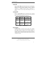
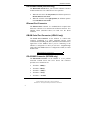
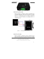
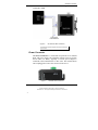
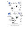
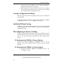
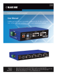
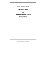
Models: LES41A, LES42A Modbus TCP to Modbus ASCII / RTU Converters Manual Documentation Number: LES4xA-2106m PN7925-rev000 Black Box Corporation - 1000 Park Drive - Lawrence, PA 15055-1018 www.blackbox.com -- Tech Support and Ordering: 724-746-5500 - Fax: 724-746-0746 i Manual Documentation Number: MES1A/MES1B-2106m PN7138-rev001 Black Box Corporation - 1000 Park Drive - Lawrence, PA 15055-1018 www.blackbox.com -- Tech Support and Ordering: 724-746-5500 - Fax: 724-746-0746 ii Table of Contents CHAPTER 1: INTRODUCTION ............................................................................. 1 ABOUT THIS MANUAL ............................................................................................... 1 SUPPORT .................................................................................................................... 1 ABOUT YOUR LES4XA CONVERTER ........................................................................ 1 FEATURES .................................................................................................................. 2 CHAPTER 2: HARDWARE OVERVIEW ............................................................. 3 PACKAGE CHECKLIST ................................................................................................ 3 INDICATORS, SWITCHES AND CONNECTORS............................................................... 3 Power LED ........................................................................................................... 3 Link LED ............................................................................................................... 4 Activity LED .......................................................................................................... 4 RS-422/485 Switch (LES42A only)........................................................................ 4 Ethernet Port Connector ....................................................................................... 5 DB-9M Serial Port Connector (LES41A only) ...................................................... 5 RS-422/485 Connector (LES42A only) ................................................................. 5 Power Connector .................................................................................................. 7 CONNECTING THE HARDWARE .................................................................................. 8 CHAPTER 3: GETTING STARTED .................................................................... 11 QUICKSTART ........................................................................................................... 11 1. Check the contents of your LES4XA package. It should contain… ............. 11 2. Set up the Hardware ................................................................................... 11 3. Software Installation ................................................................................... 11 4. Discover the LES4XA on the Network......................................................... 12 5. Configure the LES4XA ................................................................................ 12 6. Modbus Device Installation ........................................................................ 12 USING THE DEVICE INSTALLER SOFTWARE ............................................................. 13 System Requirements .......................................................................................... 13 Installing the Device Installer ............................................................................. 13 Starting the Device Installer ............................................................................... 14 Discovering Devices ........................................................................................... 14 Manual Documentation Number: LES4xA-2106m PN7925-rev000 Black Box Corporation - 1000 Park Drive - Lawrence, PA 15055-1018 www.blackbox.com -- Tech Support and Ordering: 724-746-5500 - Fax: 724-746-0746 iii Getting Device Details ........................................................................................ 15 Connecting to the LES4XA.................................................................................. 16 CHAPTER 4: CONFIGURING THE LES4XA .................................................... 19 NAVIGATING THE CONFIGURATION MENU .............................................................. 20 1) NETWORK/IP SETTINGS ....................................................................................... 22 IP Address ........................................................................................................... 22 Default Gateway ................................................................................................. 23 Netmask............................................................................................................... 24 Telnet Configuration Password .......................................................................... 24 2) SERIAL AND MODE SETTINGS .............................................................................. 25 Protocol .............................................................................................................. 25 Serial Interface.................................................................................................... 26 3) MODEM/CONFIGURABLE PIN SETTINGS............................................................... 28 4) ADVANCED MODBUS PROTOCOL SETTINGS ........................................................ 28 Slave Address / Unit ID Source........................................................................... 29 Allow Modbus Broadcasts .................................................................................. 30 Use MB/TCP 00BH/00AH Exception Responses ................................................ 30 Disable Modbus/TCP Pipeline............................................................................ 31 Character Timeout .............................................................................................. 31 Message Timeout ................................................................................................ 32 Serial TX Delay after RX .................................................................................... 32 Swap 4x/0H to Get 3x/1x..................................................................................... 32 5) UNIT ID TO IP ADDRESS LOOKUP TABLE SETTINGS ............................................ 32 Close Idle TCP Sockets After .............................................................................. 33 Redundant Entry Retries After ............................................................................ 33 Add, Delete, Exit - Select Function .................................................................... 33 Modbus Address From/To ................................................................................... 34 Slave IP Address ................................................................................................. 34 CHAPTER 5: USING OTHER DEVICE INSTALLER FEATURES ................ 35 MANAGING DEVICE LISTS ....................................................................................... 35 Creating a New Device List ................................................................................ 35 Saving Device Lists ............................................................................................. 36 Opening Device Lists .......................................................................................... 36 Device List Display Options ............................................................................... 36 Adding a Device Manually.................................................................................. 37 ASSIGNING AN IP ADDRESS (USING DEVICE INSTALLER)......................................... 38 Using Device Installer to Assign an IP Address ................................................. 38 USING THE DEVICES DETAILS TAB .......................................................................... 39 Manual Documentation Number: MES1A/MES1B-2106m PN7138-rev001 Black Box Corporation - 1000 Park Drive - Lawrence, PA 15055-1018 www.blackbox.com -- Tech Support and Ordering: 724-746-5500 - Fax: 724-746-0746 iv UPGRADING FIRMWARE ........................................................................................... 40 INSTALLING PRE-SAVED CONFIGURATION FILES ..................................................... 41 Saving Setup Records .......................................................................................... 42 Installing Setup Records ..................................................................................... 42 LOGGING SEARCH AND UPGRADE DATA ................................................................. 44 USING PING ............................................................................................................. 45 USING HELP ............................................................................................................. 45 CHAPTER 6: MODBUS BASICS .......................................................................... 47 MODBUS ASCII/RTU .............................................................................................. 47 MODBUS/TCP.......................................................................................................... 48 HINTS AND TIPS ....................................................................................................... 49 APPENDIX A: DEFAULT CONFIGURATION SETTINGS .............................. 51 APPENDIX B: PRODUCT SPECIFICATIONS .................................................. 53 APPENDIX C: DIMENSIONAL DIAGRAMS ..................................................... 55 APPENDIX D: SERIAL CONNECTIONS ........................................................... 58 APPENDIX E: NETWORK CONNECTIONS ..................................................... 60 Manual Documentation Number: LES4xA-2106m PN7925-rev000 Black Box Corporation - 1000 Park Drive - Lawrence, PA 15055-1018 www.blackbox.com -- Tech Support and Ordering: 724-746-5500 - Fax: 724-746-0746 v Manual Documentation Number: LES4xA-1207m PN7925-rev000 Black Box Corporation - 1000 Park Drive - Lawrence, PA 15055-1018 www.blackbox.com -- Tech Support and Ordering: 724-746-5500 - Fax: 724-746-0746 iv Introduction Chapter 1: Introduction Thank you for purchasing an LES41A or LES42A Modbus TCP to Modbus ASCII/RTU Converter! Like all B&B Electronics products, this product has been manufactured to the highest standards of quality and performance to ensure your complete satisfaction. About this Manual This manual has been created to assist you in installing, configuring and using the LES4XA. Please read it carefully and follow the instructions to achieve best results. Support For additional information on this and other B&B products, and for technical support, call 815.433.5100 option 3, or access B&B Electronics’ website at: www.bb-elec.com About Your LES4XA Converter LES41A and LES42A Modbus TCP to Modbus ASCII/RTU Converters are easy-to-use, cost-effective solutions for connecting new and existing Modbus ASCII/RTU serial devices to TCP/IP networks. The LES41A provides this connection for Modbus devices with RS-232 interfaces; the LES42A facilitates Modbus devices with RS-422 four-wire point-to-point interfaces, or RS-485 four or two-wire multi-drop bus connections. Manual Documentation Number: LES4xA-1207m PN7925-rev000 Black Box Corporation - 1000 Park Drive - Lawrence, PA 15055-1018 www.blackbox.com -- Tech Support and Ordering: 724-746-5500 - Fax: 724-746-0746 1 Introduction Figure 1. LES41A and LES42A Converters LES41A Converters allow new and legacy Modbus ASCII/RTU slave devices with RS-232 serial ports to operate on a TCP/IP network as full Modbus TCP slaves. All Modbus TCP devices on the network can share access to the Modbus ASCII/RTU device. LES42A Converters allow Modbus/RTU slave devices with RS-422/485 interfaces to operate on a TCP/IP network as full Modbus TCP slaves. All Modbus devices on an RS-485 bus can be connected to the TCP/IP network via the LES42A, allowing them all to be accessed by Modbus TCP/IP devices on the network. Traditional Modbus ASCII/RTU master devices also can be connected to TCP/IP networks using the LES4XA, making the device appear to be a full Modbus TCP master on the network. It can directly access Modbus TCP slave devices. It also can access other Modbus ASCII/RTU slaves that are connected to the network via other LES4XA Converters, as if it is talking directly to a Modbus ASCII/RTU slave. Features • Converts Modus ASCII/RTU to Modbus/TCP • Small, economical and configurable • LES41A supports TD, RD and GND RS-232 lines • LES42A supports TDA(-), TDB(+), RDA(-), RDB(+) RS-422/485 lines • LEDs on network connection indicate link integrity and data transfer activity • 10/100 Mbps auto-detecting operation • Removable screw terminal strips for power supply • Removable screw terminal strips for RS-422/485 connection (LES42A) • Device Installer user interface software included • DIN rail mountable Manual Documentation Number: LES4xA-1207m PN7925-rev000 Black Box Corporation - 1000 Park Drive - Lawrence, PA 15055-1018 www.blackbox.com -- Tech Support and Ordering: 724-746-5500 - Fax: 724-746-0746 2 Hardware Overview Chapter 2: Hardware Overview Package Checklist LES4XA Modbus ASCII/RTU to Modbus TCP Converters are shipped with the following items included: 9 9 9 9 the LES41A or LES42A module a printed version of this user manual a printed version of the LES4XA Quick Start Guide a CD-ROM disc with o Device Installer software o this manual in pdf format o a Quick Start guide in pdf format Indicators, Switches and Connectors Power LED The Power LED illuminates (red) immediately on power up indicating that 10 VDC to 30 VDC power is present on the Power Supply terminals. (Typically 12 VDC is used.) Figure 2. LED Indicators on the LES41A Manual Documentation Number: LES4xA-1207m PN7925-rev000 Black Box Corporation - 1000 Park Drive - Lawrence, PA 15055-1018 www.blackbox.com -- Tech Support and Ordering: 724-746-5500 - Fax: 724-746-0746 3 Hardware Overview Link LED When the Link LED located on the Ethernet jack is illuminated it indicates that a connection (link integrity) has been established between the converter and the network. Its color is green if connected to a 100BaseT network; orange if connected to a 10BaseT network. It turns orange briefly during the power up process. Activity LED When the Activity LED located on the Ethernet jack is flashing (green) it indicates data is being sent across the network. This LED turns orange briefly during the power up process. LED Color/Status Function Power Red Power applied Orange Bootup, 10BaseT Green 100BaseT Green (Blinking) Data on the network Orange Bootup Link Activity Figure 3. LED Status Table Reset Switch The Reset switch is accessible on the top edge of the LES4XA (same edge as the power supply connector) through a small hole in the LES4XA enclosure. It allows you to reset the LES4XA by inserting a small tool through the hole and pressing the momentary switch for about 1 second. The LES4XA restarts with its last saved configuration settings. Manual Documentation Number: LES4xA-1207m PN7925-rev000 Black Box Corporation - 1000 Park Drive - Lawrence, PA 15055-1018 www.blackbox.com -- Tech Support and Ordering: 724-746-5500 - Fax: 724-746-0746 4 Hardware Overview RS-422/485 Switch (LES42A only) The RS-422/485 switch allows you to set the LES42A Converter for RS-422/485 four-wire or RS-485 two-wire operation. • When the switch is in the left position, the LES42A operates in RS-422/485 four-wire mode. • When the switch is in the right position, the LES42A operates in the RS-485 two-wire mode. Ethernet Port Connector The Ethernet Port connector is a standard RJ-45 receptacle that allows the converter to be connected to an Ethernet network. Two indicator LEDs (described above) are built into the RJ-45 connector. DB-9M Serial Port Connector (LES41A only) The Serial Port Connector on the LES41A is a DB-9 male connector (configured as a DTE) supporting RS-232 serial communications including TD (Pin 3), RD (Pin 2) and GND (Pin 5) signal lines. If the Modbus device you are connecting to the LES41A is configured as a DCE you will use a straight-through serial cable. If the Modbus device is configured as a DTE, use a null modem cable. Refer to Appendix D for connection pin-outs. RS-422/485 Connector (LES42A only) The RS-422/485 connector on the LES42A is a five position removable terminal block with screw downs. The connector provides screw connections for: • Terminal 1 - RDB(+) • Terminal 2 - RDA(-) • Terminal 3 - TDB(+) • Terminal 4 - TDA(-) • Terminal 5 – Ground Manual Documentation Number: LES4xA-1207m PN7925-rev000 Black Box Corporation - 1000 Park Drive - Lawrence, PA 15055-1018 www.blackbox.com -- Tech Support and Ordering: 724-746-5500 - Fax: 724-746-0746 5 Hardware Overview Figure 4. LES42A Serial Connector RS-422/485 Four-Wire Mode When the LES42A is configured to operate in RS-422/485 fourwire mode (RS-422/485 switch in the left position) its receive terminals are connected to the transmit terminals of the Modbus device it is communicating with. Its transmit terminals are connected to the receive terminals of the Modbus device it is communicating with. Figure 5. RS-422/485 Four-Wire Connection RS-485 Two-Wire Mode When the LES42A is configured to operate in RS-485 two-wire mode (RS-422/485 switch in the right position) the two-wire RS485 two-wire communications cable pair is connected to Terminals Manual Documentation Number: LES4xA-1207m PN7925-rev000 Black Box Corporation - 1000 Park Drive - Lawrence, PA 15055-1018 www.blackbox.com -- Tech Support and Ordering: 724-746-5500 - Fax: 724-746-0746 6 Hardware Overview TDB and TDA. The communications cable ground/shield is connected to GND. Figure 6. RS-485 Two-Wire Connection No jumpers are required to bridge the transmit and receive lines in two-wire mode. Power Connector The Power Connector is a removable two-position screw terminal block with screw down. The LES4XA requires between 10 VDC and 30 VDC (3.6 Watts). Typically a 12 VDC power adapter is connected to the terminal block via bare wires. The terminal block can be unplugged to remove the converter from service. Figure 7. LES4XA Power Connector Manual Documentation Number: LES4xA-1207m PN7925-rev000 Black Box Corporation - 1000 Park Drive - Lawrence, PA 15055-1018 www.blackbox.com -- Tech Support and Ordering: 724-746-5500 - Fax: 724-746-0746 7 Hardware Overview Connecting the Hardware The LES41A is connected to its Modbus device via a DB-9M connector and an RS-232 cable. The LES41A is configured as a DTE. If the connected Modbus device is configured as a DCE, use a straight-through cable. If the connected Modbus device is configured as a DTE, use a null modem cable. Always check the interface specifications of the Modbus device to determine whether it is a DTE or DCE before connecting. The LES42A is connected to its Modbus device via the RS-422/485 terminal block. In RS-422/485 four-wire mode a cable containing two pairs and a ground/shield is used. In RS-485 two-wire mode a cable containing one pair and a ground/shield is used. Power is supplied to the converter via the power supply terminal block. Typically, the LES4XA is connected to the network via a hub switch or router using standard straight-through CAT-5 cable. (If you are connecting the LES4XA directly to a PC’s network interface a crossover Ethernet cable is required.) Manual Documentation Number: LES4xA-1207m PN7925-rev000 Black Box Corporation - 1000 Park Drive - Lawrence, PA 15055-1018 www.blackbox.com -- Tech Support and Ordering: 724-746-5500 - Fax: 724-746-0746 8 Hardware Overview Figure 8. LES41A Connections Figure 9. LES42A Connections Manual Documentation Number: LES4xA-1207m PN7925-rev000 Black Box Corporation - 1000 Park Drive - Lawrence, PA 15055-1018 www.blackbox.com -- Tech Support and Ordering: 724-746-5500 - Fax: 724-746-0746 9 Hardware Overview Manual Documentation Number: LES4xA-1207m PN7925-rev000 Black Box Corporation - 1000 Park Drive - Lawrence, PA 15055-1018 www.blackbox.com -- Tech Support and Ordering: 724-746-5500 - Fax: 724-746-0746 10 Getting Started Chapter 3: Getting Started QuickStart The following section is a quick, step-by-step procedure that will assist you to get started configuring the LES4XA. Additional details on how to use the Device Installer software to discover and connect to devices is included in the section following this one. LES4XA configuration details are included in Chapter 4. 1. Check the contents of your LES4XA package. It should contain… The LES41A or LES42A unit A printed version of this user manual A printed version of the LES4XA Quick Start Guide Software CD with Device Installer software, this manual, Quick Start guide 2. Set up the Hardware Connect the LES4XA to the network using an Ethernet cable. Connect your PC to the network Connect a 12 VDC power supply (not included) to the LES4XA and apply power. (10 to 30 VDC, 3.6 Watts.) 3. Software Installation Insert the software CD and it should auto-start into the installation wizard. Follow the on-screen installation wizard to install the Device Installer software. Manual Documentation Number: LES4xA-1207m PN7925-rev000 Black Box Corporation - 1000 Park Drive - Lawrence, PA 15055-1018 www.blackbox.com -- Tech Support and Ordering: 724-746-5500 - Fax: 724-746-0746 11 Getting Started 4. Discover the LES4XA on the Network Open the Device Installer software. It should detect the LES4XA and display XPort in the third level of the Devices Tree. Expand the Devices Tree and click the device IP Address. Select the Telnet Configuration tab, then click Connect. When the Modbus/TCP to RTU Bridge, MAC address and Software version information appears, Press Enter to go into Setup Mode. 5. Configure the LES4XA To change the IP Address, Default Gateway or Netmask, type 1. To configure Master/Slave and serial Interface settings, type 2. Do not change any configuration settings in section 3. To configure Modbus/TCP settings, type 4. To configure Modbus Master settings, type 5. To save your settings to the LES4XA, type S. 6. Modbus Device Installation Connect the Modbus device to the serial interface on the LES4XA using the correct cabling: LES41A is a DTE: Use a straight through serial cable if the Modbus device is a DCE; null modem if device is DTE. LES42A: Four-wire for RS-422, Two-wire for RS-485, Set RS-422/485 switch. Your Modbus device should now be operational on the network. Note: The LES4XA can be reset (rebooted) by pressing the Reset switch for one second. Reset switch is accessed through a small hole in the top of the enclosure. Manual Documentation Number: LES4xA-1207m PN7925-rev000 Black Box Corporation - 1000 Park Drive - Lawrence, PA 15055-1018 www.blackbox.com -- Tech Support and Ordering: 724-746-5500 - Fax: 724-746-0746 12 Getting Started Using the Device Installer Software This section provides more detailed information on how to install and use the Device Installer software. Device Installer is used to set up and configure the LES4XA on a network. It detects all LES4XAs on the network and allows you to configure the network and serial port settings. It also allows you to monitor the LES4XA and verify its status. System Requirements • Windows XP, Windows 2000, Windows NT4.0 (with service pack 6.0a or later), Windows ME, or Windows 98 • Internet Explorer 5.01 or later • 30 MB hard drive space • 64 MB RAM Installing the Device Installer Note: Device Installer requires Microsoft .NET software to operate. To install the Device Installer software: 1. Insert the CD included with your LES4XA into the CD ROM drive of your PC. 2. The installation should launch automatically. If not: a. Click Start on the Task Bar and select Run b. Type in [CD drive letter]:\Launch.exe 3. When the Device Installer Setup Wizard dialog box appears, click Next to open the Select Installation Folder dialog box. 4. Accept the suggested installation folder or click Browse… to select a different installation folder. 5. Click Next to open the Confirm Installation dialog box. Manual Documentation Number: LES4xA-1207m PN7925-rev000 Black Box Corporation - 1000 Park Drive - Lawrence, PA 15055-1018 www.blackbox.com -- Tech Support and Ordering: 724-746-5500 - Fax: 724-746-0746 13 Getting Started 6. Click Next to begin the installation. When finished, the Installation Complete dialog box appears. Starting the Device Installer Run the Device Installer from the Start, Programs, Lantronix, DeviceInstaller menu. Discovering Devices When Device Installer opens it automatically scans the network for LES4XA devices. Any of the following steps will initiate a manual search for devices: • Click the Search icon • On the Device menu, click Search • Press the F5 function key When discovered for the first time, any LES4XA devices present are listed in the Devices Tree pane and Device List pane as XPort and XPort IAP respectively. (XPort is the name of the internal module of the LES4XA.) The Devices Tree shows a hierarchy including any network bridges under which the LES4XA is found. The Device List pane is a table showing: • Device Type • Device Name • Group • IP Address • Hardware (MAC) Address • Status Manual Documentation Number: LES4xA-1207m PN7925-rev000 Black Box Corporation - 1000 Park Drive - Lawrence, PA 15055-1018 www.blackbox.com -- Tech Support and Ordering: 724-746-5500 - Fax: 724-746-0746 14 Getting Started Figure 10. The Device Installer Main Window Getting Device Details The Device Installer provides a variety of information about the LES4XA under the Device Details tab. To access the Device Details tab: 1. Expand the Device Tree by clicking the + symbol next to XPort. Keep expanding until the IP Address of the LES4XA appears. 2. Click the IP Address on the Device Tree. The Device Details tab appears where the Device List was. Figure 11. Device Details Tab Manual Documentation Number: LES4xA-1207m PN7925-rev000 Black Box Corporation - 1000 Park Drive - Lawrence, PA 15055-1018 www.blackbox.com -- Tech Support and Ordering: 724-746-5500 - Fax: 724-746-0746 15 Getting Started Note: The Web Configuration tab is not used with the LES4XA. Connecting to the LES4XA Before configuration can occur you must set up a telnet connection with the LES4XA to access the Configuration Menu. You can access the Configuration Menu using a standard telnet window, or use the telnet implementation within the Device Installer software. The Device Installer option provides an all-in-one user interface for working with the LES4XA To connect: 3. Select the Telnet Configuration tab. The tab shows the IP Address of the LES4XA and the Port Number used to communicate with it via telnet. The rest of the window is blank. 4. Click Connect to connect to the LES4XA. When a connection is established the following window appears, which contains information on the MAC address and Software version of the LES4XA. Figure 12. Press Enter to go into Setup Mode The background color of the window remains white for five seconds, then changes to gray when it times out. 5. Press the Enter key within five seconds to go into Setup Mode or it will time out (and you will have to click Clear and repeat the process). The LES4XA Configuration Menu appears. Manual Documentation Number: LES4xA-1207m PN7925-rev000 Black Box Corporation - 1000 Park Drive - Lawrence, PA 15055-1018 www.blackbox.com -- Tech Support and Ordering: 724-746-5500 - Fax: 724-746-0746 16 Getting Started Figure 13. Telnet Configuration Tab with Settings Refer to Chapter 4 for configuration details. Manual Documentation Number: LES4xA-1207m PN7925-rev000 Black Box Corporation - 1000 Park Drive - Lawrence, PA 15055-1018 www.blackbox.com -- Tech Support and Ordering: 724-746-5500 - Fax: 724-746-0746 17 Getting Started Manual Documentation Number: LES4xA-1207m PN7925-rev000 Black Box Corporation - 1000 Park Drive - Lawrence, PA 15055-1018 www.blackbox.com -- Tech Support and Ordering: 724-746-5500 - Fax: 724-746-0746 18 Configuring the LES4XA Chapter 4: Configuring the LES4XA Configuration of the LES4XA is accomplished from the Configuration Menu, which is accessed via a standard telnet window, or through the telnet implementation within the Device Installer software. Note: The Web Configuration tab is not used with the LES4XA. Figure 14. Telnet Configuration Tab Manual Documentation Number: LES4xA-1207m PN7925-rev000 Black Box Corporation - 1000 Park Drive - Lawrence, PA 15055-1018 www.blackbox.com -- Tech Support and Ordering: 724-746-5500 - Fax: 724-746-0746 19 Configuring the LES4XA Navigating the Configuration Menu On initial power-up there are four sections in the LES4XA configuration menu. A fifth menu item appears if you are configuring a Modbus Master device. The menu items are: 6. Network/IP Settings 7. Serial & Mode Settings 8. Modem/Configurable Pin Settings 9. Advanced Modbus Protocol Settings The following menu item 5) appears if the LES4XA is configured as a Modbus Master in section 2) Serial Protocol 10. Unit ID to IP Address Table Each section of the configuration menu includes several parameters. 11. Begin the configuration by typing the menu section number at the Select Command or parameter set (1..4) to change: prompt. The first configuration parameter of the section will appear at the bottom of the pane. The current setting is shown in brackets. Example: Figure 15. Setting the IP Address Manual Documentation Number: LES4xA-1207m PN7925-rev000 Black Box Corporation - 1000 Park Drive - Lawrence, PA 15055-1018 www.blackbox.com -- Tech Support and Ordering: 724-746-5500 - Fax: 724-746-0746 20 Configuring the LES4XA 12. To change the parameter, type in a new value, then press Enter. If you wish to leave the parameter as it was, simply press Enter. A prompt for the next parameter will appear. 13. When all parameters in the currently selected section are complete you will again be prompted to select a menu item. Select another section and continue the configuration process. Saving Configuration Settings When all categories have been configured you must save your configuration to the LES4XA. To Save the configuration settings to the LES4XA, at the Select Command or parameter set (1..4) to change: prompt type S. Quitting Without Saving To Quit the configuration session without saving, type Q. The background color will change to gray and the LES4XA will re-start without updating the configuration settings. Reconfiguring to Factory Settings The LES41A and LES42A come from the factory preconfigured for correct operation with their respective interfaces. The following procedure describes how you can return the LES41A and LES42A to their original factory settings. To Reconfigure the LES41A to Factory Settings: Type D at the Select Command or parameter set (1..4) to change: prompt. The Configuration Menu is updated with the new settings displayed. To Reconfigure the LES42A, to Factory Settings: 14. Type D at the Select Command or parameter set (1..4) to change: prompt. Manual Documentation Number: LES4xA-1207m PN7925-rev000 Black Box Corporation - 1000 Park Drive - Lawrence, PA 15055-1018 www.blackbox.com -- Tech Support and Ordering: 724-746-5500 - Fax: 724-746-0746 21 Configuring the LES4XA 15. Type 2 to enter the Serial & Mode Settings section and set the Serial Mode for RS-485 Two-Wire (see the next section for details). 16. Type 3 to enter the Modem/Configurable Pin Settings section and set CP1 to RS-485 Enable Wire (see the next section for details).. See the following sections for details on how to set Serial & Mode Settings and Modem/Configurable Pin Settings. 1) Network/IP Settings In the Network/IP Settings section of the Configuration Menu you can configure: • IP Address of the LES4XA • Default Gateway • Netmask • Telnet Configuration Password IP Address Every device connected to a TCP/IP network must have a unique IP Address. This includes every LES4XA. However, there is more than one way to set up an IP address for the LES4XA DHCP The LES4XA is shipped with a default IP address of 0.0.0.0. This configures the converter to obtain an IP address via DHCP (Dynamic Host Configuration Protocol) from a DHCP server on the network when the LES4XA boots up. If a DHCP server is available to respond to the DHCP request, the LES4XA will receive an IP address, gateway address and subnet mask from the server. A DHCP-generated IP address will appear in the Device Tree, Device List and at the top of the Telnet Configuration tab, but it will not be displayed in the IP Address field of the Network/IP Settings section of the Configuration Menu. Manual Documentation Number: LES4xA-1207m PN7925-rev000 Black Box Corporation - 1000 Park Drive - Lawrence, PA 15055-1018 www.blackbox.com -- Tech Support and Ordering: 724-746-5500 - Fax: 724-746-0746 22 Configuring the LES4XA Figure 16. Network/IP Settings Menu Auto-IP If a DHCP server is NOT available on the network, the LES4XA will revert to Auto-IP and generate its own IP address in the 169.254.xxx.xxx range. Static IP Address The IP address of the LES4XA can be changed via the Telnet Configuration Menu interface. To determine an appropriate static IP address, consult your network administrator. The Device Installer Help feature also provides some useful information related to IP addressing. 17. At the Select Command or parameter set (1..4) to change: prompt, type 1. 18. At the IP Address (000)prompt o o To keep the current setting, press Enter To change the IP address, type the first octet Press Enter to accept the change Repeat for all octets 19. Press Enter to accept the new IP address After the new settings have been accepted they will appear in the Configuration Menu. After the Configuration has been saved to the LES4XA, the new settings will appear in the Device Details tab. The IP Address can also be changed from the Device Installer menu. See Chapter 5 for details. Default Gateway A Default Gateway address is only required if your LES4XA must communicate with devices on remote TCP/IP networks through a router or gateway. The default value for this parameter is ---not set---. Manual Documentation Number: LES4xA-1207m PN7925-rev000 Black Box Corporation - 1000 Park Drive - Lawrence, PA 15055-1018 www.blackbox.com -- Tech Support and Ordering: 724-746-5500 - Fax: 724-746-0746 23 Configuring the LES4XA • If you DO NOT require remote communication, type N or just press Enter at the Set Gateway IP Address (N) prompt. • If you DO require remote communication through a router or gateway, type Y. The Gateway IP Address: (000) prompt appears. Enter the IP address of the default gateway within your local network by typing each address octet followed by pressing Enter. After the new settings have been accepted they will appear in the Configuration Menu. After the Configuration has been saved to the LES4XA, the new settings will appear in the Device Details tab. Netmask Typically you will type N, or just press Enter to cause the LES4XA to automatically use the standard Netmask appropriate for the IP address being used. The default value for this parameter is ---not set---. To change the Netmask setting 20. Press Enter to keep the current setting 21. Press Y to change the setting 22. At the prompt type in four octets representing the new Netmask. After the new settings have been accepted they will appear in the Configuration Menu. After the Configuration has been saved to the LES4XA, the new settings will appear in the Device Details tab. For more information or direction on the netmask you may require, consult your network administrator. Telnet Configuration Password You can set up a Telnet Configuration Password to control unauthorized access to the Telnet Configuration interface. 23. Type Y. The Enter New Password: prompt appears. 24. Type in a password. The words Telnet config password set appears in the 1) section of the configuration menu. The default value for this parameter is N (for Not Set). Manual Documentation Number: LES4xA-1207m PN7925-rev000 Black Box Corporation - 1000 Park Drive - Lawrence, PA 15055-1018 www.blackbox.com -- Tech Support and Ordering: 724-746-5500 - Fax: 724-746-0746 24 Configuring the LES4XA Warning: Do not forget your password if used. There is no easy way to get into the unit for configuration once you forget your password. 2) Serial and Mode Settings In the Serial and Mode Settings section of the Configuration Menu you can configure: • the serial Protocol to be used with your Modbus device • the Serial Interface type and communications parameters Figure 17. Serial & Mode Settings Menu To configure Serial and Mode Settings, type 2 at the Select Command or parameter set (1..4) to change: prompt. The Attached Device prompt appears. Protocol Protocol parameters must be set to match the type of Modbus device (master or slave) connected to the serial side of the LES4XA device, and the type of Modbus protocol (ASCII or RTU) that will be used. Attached Device Modbus devices operate as either Masters (polling Slaves) or Slaves (responding to polls from Masters). An example of a Modbus master is a computer running HMI (human machine interface) software. Examples of Modbus slaves are controllers, remote terminal units (RTU) or programmable logic controllers (PLC). To configure the type of Attached Device: 25. At the Attached Device (1=Slave 2=Master)(1) prompt o o o To keep the current setting, press Enter To select Slave, type 1 To select Master, type 2 Manual Documentation Number: LES4xA-1207m PN7925-rev000 Black Box Corporation - 1000 Park Drive - Lawrence, PA 15055-1018 www.blackbox.com -- Tech Support and Ordering: 724-746-5500 - Fax: 724-746-0746 25 Configuring the LES4XA 26. To accept changes, press Enter Note: When Master mode is selected a fifth item (Unit ID -> IP Address Table is added to the Configuration Menu. Serial Protocol Modbus devices communicate in either of two Serial Protocols: ASCII or RTU. Modbus/ASCII protocol is slower and uses two ASCII characters to represent each 8 bit data byte. Modbus/RTU uses 8 bit binary data characters. The LES4XA must be configured to use the same protocol used by the attached Modbus device. To configure the type of Serial Protocol 27. At the Serial Protocol (1=Modbus/RTU 2=Modbus/ASCII) (1) prompt o o o To keep the current setting, press Enter To select Modbus/RTU, type 1 To select Modbus/ASCII, type 2 28. To accept changes, press Enter Serial Interface Serial Interface parameters include the type of interface and the data rate/format of the data. The LES4XA must use the same type of interface and serial parameters as that of the Modbus device it is connected to. LES41A Serial Interface Since the LES41A is designed with an RS-232 interface, its default Interface Type is RS-232. Although RS-422/485 four-wire and RS-485 two-wire options are given in the configuration menu, reconfiguring the LES41A for anything other than RS-232 will prevent the device from operating correctly. LES42A Serial Interface The LES42A is designed with an RS-422/485 interface and can be configured for four-wire operation or two-wire operation. Manual Documentation Number: LES4xA-1207m PN7925-rev000 Black Box Corporation - 1000 Park Drive - Lawrence, PA 15055-1018 www.blackbox.com -- Tech Support and Ordering: 724-746-5500 - Fax: 724-746-0746 26 Configuring the LES4XA Although RS-232 option is provided in the configuration menu, reconfiguring the LES42A for RS-232 will prevent the device from operating correctly. To configure Interface Type parameters: 29. At the Interface Type (1=RS232 2=RS422/RS485+4-wire 3=RS485+2-wire) (3) prompt: o o o To keep the current setting, press Enter To select RS-422/RS-485 four-wire, type 2 To select RS-485 two-wire, type 3 30. To accept changes, press Enter When RS-422/485 four-wire operation is selected: When RS-422/485 four-wire operation is selected the RS-422/485 switch on the LES42A must be in the left position. When RS-485 two-wire operation is selected: • CP1 (configured in the next section under Modem/Configurable Pin Settings) must be enabled to ensure Send Data control is implemented. • The RS-422/485 switch on the LES42A must be in the right position. • The multidrop bus is connected to Terminals 3 [DataB(+) to TDB(+) terminal] and 4 [DataA(-) to TDA(-) terminal]. • No jumpers are required to bridge transmit and receive lines on the terminal block Serial Parameters LES4XA Serial Parameters must be set up to match the parameters of the Modbus device connected to its serial interface. LES4XA Serial Parameter options include: • Data rates from 300 bps to 115200 bps • 7 or 8 data bits • No, Even or Odd parity • 1 or 2 stop bits. To configure Serial Parameters: Manual Documentation Number: LES4xA-1207m PN7925-rev000 Black Box Corporation - 1000 Park Drive - Lawrence, PA 15055-1018 www.blackbox.com -- Tech Support and Ordering: 724-746-5500 - Fax: 724-746-0746 27 Configuring the LES4XA 31. At the Enter serial parameters (9600,8,N,1)prompt o o To keep the current setting, press Enter To change the serial parameters, type in new parameters in the format 9600,8,N,1 32. To accept changes, press Enter 3) Modem/Configurable Pin Settings There is only one configurable setting required in the Modem/Configurable Pin Settings section of the Configuration Menu. When configuring an LES42A for RS-485 two-wire operation, the CP1 parameter must be set for RS485 Enable to ensure Send Data Control is implemented. No configuration is required in this section for LES41A converters. To configure RS485 Enable in the Modem/Configurable Pin Settings section: 33. Type 3 at the Select Command or parameter set (1..4) to change: prompt. The CP1 Function prompt appears. 34. Type 4 to select RS485 Enable 35. To accept the change, press Enter 36. Press Enter three more times to exit the Modem/Configurable Pin Settings section of the Configuration Menu. 4) Advanced Modbus Protocol Settings In the Advanced Modbus Protocol Settings section of the Configuration Menu you can configure: • whether the Slave Address is fixed or used as received • whether to Allow Modbus Broadcasts • whether to Use MB/TCP 00BH/00AH Exception Responses • whether to Disable Modbus/TCP Pipeline • Character Timeout values • Message Timeout values Manual Documentation Number: LES4xA-1207m PN7925-rev000 Black Box Corporation - 1000 Park Drive - Lawrence, PA 15055-1018 www.blackbox.com -- Tech Support and Ordering: 724-746-5500 - Fax: 724-746-0746 28 Configuring the LES4XA • Serial TX delay after RX values • whether to Swap 4x/0H to get 3x/1x register conversions Figure 18. Advanced Modbus Protocol Settings Menu Slave Address / Unit ID Source All devices connected to a TCP/IP network require a unique IP address. Each LES4XA Converter has a unique IP address on the network, allowing messages to be directed to it. However, when multiple Modbus/RTU devices are connected to the RS-485 bus of an LES42A there must be a way to address them individually. Standard Modbus/RTU fields are encapsulated inside Modbus/TCP messages. Modbus/RTU’s Slave Address field is called the Unit ID in Modbus/TCP. The Unit ID is used to specify a particular Modbus/RTU device on the serial side of the LES4XA. When the LES4XA receives a message (sent to its IP address), it looks at the Unit ID field of the message and passes the message to the specified slave. 0 for Auto Setting the Slave Address field to 0 allows the LES4XA to use the Unit ID received from a Modbus master to direct messages to a specific slave address. The LES4XA receives the Unit ID number on the Modbus/TCP side and passes it along as the Slave Address on the serial side of the converter. 1…255 Unfortunately, some early Modbus/TCP products assumed that each IP address would have only one slave. These products always set their Unit ID to 0 (relying on the IP address only to address the slave). The lack of an appropriate Unit ID presents a problem for the LES42A. It must include a Slave Address in its messages to Modbus/RTU slaves. To overcome this problem, the LES4XA Slave Address field can be set to the address of one Modbus/RTU slave (any number in the range of 1 to 255). Manual Documentation Number: LES4xA-1207m PN7925-rev000 Black Box Corporation - 1000 Park Drive - Lawrence, PA 15055-1018 www.blackbox.com -- Tech Support and Ordering: 724-746-5500 - Fax: 724-746-0746 29 Configuring the LES4XA This limits the number of slaves that can be connected to the LES4XA to one, but ensures that when any message for the LES4XA’s IP address is received (regardless of its Unit ID), it is passed along to the slave. To configure the Slave Address field: • If Modbus TCP masters on your system use appropriate Unit ID addresses, select 0. You will be able to connect multiple Modbus/RTU slaves with RS-485 interfaces to an LES42A. • If any Modbus TCP masters on your system use 0 for all Unit ID fields, select a slave address that matches the Modbus/RTU slave attached to your LES4XA. You will not be able to connect multiple slaves to the RS-485 multidrop bus. Allow Modbus Broadcasts If you configured the Slave Address for any number between 1 and 255 the Allow Modbus Broadcasts does not appear in the menu. When a Modbus/RTU slave receives a slave address of 0 it interprets this as a broadcast message. All slaves accept the message. Setting the Allow Modbus Broadcasts (1=Yes, 2=No)to No reassigns a Unit ID of 0 from a Modbus TCP master as a slave address 1. This ensures that a Unit ID is not interpreted as a broadcast message. Use MB/TCP 00BH/00AH Exception Responses In Modbus/RTU, when a master initiates a query it expects to receive a response. If it does not receive one within an acceptable length of time it interprets the silence as an indication that a communications error has occurred. Because delays in TCP/IP networks are not predictable, problems can occur. To address this, Modbus/TCP defines two exception codes that can be enabled to be sent in the event of a communications failure. 1 = No If Use MB/TCP 00BH/00AH Exception Responses (1=No 2=Yes)is disabled (1=No), the LES4XA operates like a Modbus/RTU slave. It answers timeouts, un-configured slave addresses and CRC errors with silence. Manual Documentation Number: LES4xA-1207m PN7925-rev000 Black Box Corporation - 1000 Park Drive - Lawrence, PA 15055-1018 www.blackbox.com -- Tech Support and Ordering: 724-746-5500 - Fax: 724-746-0746 30 Configuring the LES4XA 2 = Yes If the Use MB/TCP 00BH/00AH Exception Responses (1=No 2=Yes)is enabled (2 = Yes), the LES4XA will return the following codes under any of the conditions described: 0A (hex) - Path Unavailable • If it receives a query from a Modbus master in which the Unit ID specifies a Slave Address not listed in the Unit ID to IP Mapping Table • If the TCP socket fails to open. 0B (hex) - Target Device Failed to Respond • If the slave did not answer, or the answer contained a CRC error • If a TCP socket is open, but no response is received within the defined message timeout period • If a TCP socket is open, but the remote Modbus TCP slave/server returned exception 0B (hex) Disable Modbus/TCP Pipeline Typically a Modbus master issues a query and waits for a response before issuing another. However, when using Modbus/TCP, multiple queries can be issued and the LES4XA will buffer them in a “pipeline”. The LES4XA can fetch each query one at a time, and respond. In some situations this is useful, but in others the sequence of query/response can get out of sync (especially if any queries or responses are lost). The Disable Modbus/TCP Pipeline setting allows you to decide how you want the system to operate. • Setting this field to 1 = No configures the LES4XA to allow pipeline operation. This is considered the safest default setting. It is recommended that you choose this option unless you are experiencing problems. • Setting this field to 2 = Yes configures the LES4XA to always fetch the latest request from the TCP buffer (discarding all older requests). Character Timeout Although Modbus/RTU specifies a 3.5 character time out period between characters, the Character Timeout field allows you to set a custom value for this field. Manual Documentation Number: LES4xA-1207m PN7925-rev000 Black Box Corporation - 1000 Park Drive - Lawrence, PA 15055-1018 www.blackbox.com -- Tech Support and Ordering: 724-746-5500 - Fax: 724-746-0746 31 Configuring the LES4XA • If you set this field to 0, the LES4XA will automatically calculate a minimum timeout based on the baud rate being used. • Although you can set this field to any value between 1 milliseconds and 6959 milliseconds, a recommended safe value for general use is about 50 milliseconds (which is the default value). Message Timeout The Message Timeout field allows you to set the timeout period for responses from a connected slave to any value between 200 milliseconds and 65000 milliseconds. The default value is 5000 milliseconds. Serial TX Delay after RX When the LES4XA receives a request from a master it relays the request to the Modbus slave connected to the LES4XA’s serial connection. When the slave responds a timer is triggered and, after the delay time configured in the Serial TX Delay after TX field, the next master request is allowed to pass through the serial connection to the slave. When using 2-wire RS-485 connections, this delay value can be set to ensure that RS-485 devices have time to disable their drivers and enable their receivers to receive the next request. Typically this is not a concern and the default value is 0. The delay can be set to a maximum of 1275 milliseconds. Swap 4x/0H to Get 3x/1x This field allows you to configure the LES4XA to convert holding register (4x) data to input register (3x) data, and convert coil (0x) data to contact (1x) data. This is useful when connecting to Modicon I/O scanners. 5) Unit ID to IP Address Lookup Table Settings The Configuring Unit ID to IP Address Table Settings section of the Configuration Menu becomes available if the LES4XA has been configured as a Modbus Master in Configuration Menu section 2). From Configuration Menu section 5) you can configure: • whether to Close Idle TCP Sockets after a specified number of seconds • whether to enable Redundant entry retries after a specified number of seconds Manual Documentation Number: LES4xA-1207m PN7925-rev000 Black Box Corporation - 1000 Park Drive - Lawrence, PA 15055-1018 www.blackbox.com -- Tech Support and Ordering: 724-746-5500 - Fax: 724-746-0746 32 Configuring the LES4XA • the Unit ID to IP Address Lookup Table Figure 19. Unit ID -> IP Address Table Settings Menu Close Idle TCP Sockets After The Close Idle TCP Sockets After field allows you to configure whether a socket is held open, or the number of seconds to hold the last socket open. • If you configure this field for 0 it hold a single socket open to the last remote Modbus TCP slave accessed • If you configure this field for any value between 3 and 60 seconds, it will close the last socket after the configured length of idle time. Redundant Entry Retries After The Redundant Entry Retries After field allows you to disable redundant retries or set a maximum length of time for retries. • If you configure this field for 0 is disables the feature. • If you configure this field for any value between 15 seconds and 60 seconds it will set the retry period to the configure time. Add, Delete, Exit - Select Function The Add, Delete, Exit - Select Function field is the starting point for managing entries in the IP Address Table. • Type A to add an entry. The Modbus addr from prompt appears. • Type D to delete an entry. The Delete entry number prompt appears. • Type E to exit. Manual Documentation Number: LES4xA-1207m PN7925-rev000 Black Box Corporation - 1000 Park Drive - Lawrence, PA 15055-1018 www.blackbox.com -- Tech Support and Ordering: 724-746-5500 - Fax: 724-746-0746 33 Configuring the LES4XA Modbus Address From/To Configuring these fields sets up the range of Modbus slave addresses that will be forwarded to the IP address (that you will configure in the next step). The prompt: Modbus addr from (1) indicates that no slave addresses have been added to the list so far. If other slave addresses have already been configured, the number will reflect the first available slave address number. 37. Press Enter to accept (1) as the first slave address number, or type in the number you prefer. After you press Enter, the Modbus Address To prompt appears. 38. Type in an slave address number that reflects the range of slaves that will be found at the IP address that will be entered in the next step. When you press Enter the Slave IP address prompt appears. Slave IP Address Type in the four octets of the IP address of the slaves being addressed. • If you configure the last octet as 000 the LES4XA will use the Slave Address/Unit ID of the slave as part of the IP address. This allows a Modbus/RTU master (connected through the LES4XA) to access up to 255 remote Modbus TCP slaves. • If you configure the last octet for a number between 1 and 254, all slave polls in this group will be sent to the same IP address. Manual Documentation Number: LES4xA-1207m PN7925-rev000 Black Box Corporation - 1000 Park Drive - Lawrence, PA 15055-1018 www.blackbox.com -- Tech Support and Ordering: 724-746-5500 - Fax: 724-746-0746 34 Using Other Device Installer Features Chapter 5: Using Other Device Installer Features In addition to the capabilities already mentioned, the Device Installer software provides other important and useful features. This section provides a brief overview of those features. For more information, access the Help files from the main menu. Device Installer features which are not used or supported by the LES4XA include: • Console Mode (via Serial port) configuration • Recover Firmware (Tools menu, Advanced selection) • Web Configuration Managing Device Lists This section included information on how to: • Create a New Device List • Save a Device List • Open a Device List • Configure Device List Display Options Creating a New Device List To create a new Device List, on the File menu, select New. The Device Installer software will create a new list but will not initiate a search to discover devices on the network. To initiate a search, select Search On the Device menu, click the Search Icon or press F5. Manual Documentation Number: LES4xA-1207m PN7925-rev000 Black Box Corporation - 1000 Park Drive - Lawrence, PA 15055-1018 www.blackbox.com -- Tech Support and Ordering: 724-746-5500 - Fax: 724-746-0746 35 Using Other Device Installer Features Saving Device Lists After a list of LES4XA devices has been discovered on the network, you can save the list, including details such as the Device Name, Group, Comments and IP Address. To save a Device List, On the File menu, select Save or Save As, type in a file name of your choice and click Save. Note: The configuration of the LES4XA is NOT saved using this method. To store the configuration in the LES4XA, on the Telnet Configuration Menu, set up the configuration, then type S at the Default settings, Save, Quit without Save prompt. To store the configuration in a Setup Record file see the procedure later in this chapter. Opening Device Lists To open an existing Device List, on the File menu, select Open. In the Open dialog box that appears, select or type in a file name and click Open. The LES4XA will search for all devices listed in the Device List file and display them in the Devices Tree. Devices not listed in the Device List file will not be shown. To discover other devices not already on the list you must initiate a search. Device List Display Options Device Installer provides several options for displaying devices in the Device Tree and List. Display Devices Using Icons • On the View menu, select Device List, then select Icons. Figure 20. Device List Icon View Manual Documentation Number: LES4xA-1207m PN7925-rev000 Black Box Corporation - 1000 Park Drive - Lawrence, PA 15055-1018 www.blackbox.com -- Tech Support and Ordering: 724-746-5500 - Fax: 724-746-0746 36 Using Other Device Installer Features Display the Hardware (MAC) Address • On the View menu, select Device Node Text, then select Hardware Address. Figure 21. Device Node Hardware Address View Display the Device Name • On the View menu, select Device Node Text, then select Name. Figure 22. Device Node Name View Adding a Device Manually Although you will typically discover LES4XA devices on the network using the Search tool, you can also add a device to the network manually. To do so you must know the IP address of the device. Manual Documentation Number: LES4xA-1207m PN7925-rev000 Black Box Corporation - 1000 Park Drive - Lawrence, PA 15055-1018 www.blackbox.com -- Tech Support and Ordering: 724-746-5500 - Fax: 724-746-0746 37 Using Other Device Installer Features Figure 23. Add Device Dialog Box To manually add a device to the Device List: 39. On the Device menu, select Add Device. 40. In the Add Device dialog box, type the IP address of the device. 41. Click OK • If a device with that IP address is not found on the network a dialog box will appear indicating Device at [IP address] was not found! • If a device is found it will be listed in the Device Tree and the Device Details tab for the device appears. Assigning an IP Address (using Device Installer) The LES4XA can obtain its IP address in several ways: • Via DHCP when it is first connected to the network (See Chapter 4) • By changing the IP address from the Telnet Configuration Menu (See Chapter 4) • Using the Assign IP feature of the Device Installer software Using Device Installer to Assign an IP Address To use Device Installer to Assign an IP address: 42. Click the Assign IP icon, press F7, or on the Device menu, select Assign IP Address. The Assign IP Address wizard appears. If a specific LES4XA device is not selected in the Devices Tree, the first page of the wizard will ask for the Hardware (MAC) Address of the device to be configured. You will find the Hardware Address of your particular LES4XA on a sticker attached to the device. Type the Hardware Address into the wizard and click next. 43. Since the LES4XA is pre-configured to use DHCP (its IP address is pre-configured for 0.0.0.0 which causes it to use DHCP). Therefore, do not use the Obtain an IP address automatically option in the wizard. Manual Documentation Number: LES4xA-1207m PN7925-rev000 Black Box Corporation - 1000 Park Drive - Lawrence, PA 15055-1018 www.blackbox.com -- Tech Support and Ordering: 724-746-5500 - Fax: 724-746-0746 38 Using Other Device Installer Features 44. If you wish to assign a different IP address to the LES4XA, select Assign a specific IP address and click Next. The IP Settings page of the wizard appears. 45. Type the desired IP address into the appropriate text box. 46. If required, type the Subnet Mask and Default Gateway addresses into the appropriate text boxes. 47. Click Next. The Assignment page of the wizard appears. 48. Click Assign. A Progress of task bar graph appears. When the process is Completed successfully, click Finish. 49. The new IP address appears in the Devices Tree, Device Details tab and Telnet Configuration tab. Using the Devices Details Tab The Device Details tab provides useful information about the LES4XA currently selected in the Device List. Figure 24. Device Details Tab Manual Documentation Number: LES4xA-1207m PN7925-rev000 Black Box Corporation - 1000 Park Drive - Lawrence, PA 15055-1018 www.blackbox.com -- Tech Support and Ordering: 724-746-5500 - Fax: 724-746-0746 39 Using Other Device Installer Features Although most fields in are fixed, the Name, Group and Comments fields are user configurable, allowing you to add information specific to your application. To change any of these fields, double-click the field, then type your text into the text box that appears. Figure 25. Adding Info to the Device Details Tab Upgrading Firmware From time to time updated firmware versions for the LES4XA may become available. Device Installer provides a Device Upgrade Wizard which can be used to install updated firmware into the LES4XA. To install firmware in the LES4XA: On the Device menu, select Upgrade…, or click the Upgrade icon. The Device Upgrade Wizard – Step 1 of 5 dialog box appears. Figure 26. Device Upgrade Wizard Step 1 50. If an Installation File (lxi) has already been created, select Use a specific installation file (LXI) (previously saved by user) Manual Documentation Number: LES4xA-1207m PN7925-rev000 Black Box Corporation - 1000 Park Drive - Lawrence, PA 15055-1018 www.blackbox.com -- Tech Support and Ordering: 724-746-5500 - Fax: 724-746-0746 40 Using Other Device Installer Features 51. If an Installation File has not been created, select Create a custom installation by specifying individual files (Typical) and then click Next. 52. In the Device Upgrade Wizard – Step 2 of 5 dialog box, browse to find the Firmware (ROM, SYS & SPB) File, then click Next. 53. In the Device Upgrade Wizard – Step 3 of 5 dialog box, select No other files to install (typical), then browse and select the previously saved Setup file. 54. In the Device Upgrade Wizard – Step 4 of 5 dialog box, click Next. The Device Upgrade Wizard – Step 5 of 5 dialog box appears and displays a bar graph indicating progress. Succeeded appears next to a listing of each step as it is accomplished. Figure 27. Device Upgrade Wizard – Step 5 of 5 Installing Pre-Saved Configuration Files The same wizard can be used to install previously saved configuration settings (Setup Records) into the LES4XA. This can be useful if you want to configure multiple LES4XAs with the same settings, or if you must replace an LES4XA and want to load identical settings into the new unit. To use the Upgrade Wizard to install configuration setting in an LES4XA you must first save the settings in the form of a Setup Record. Manual Documentation Number: LES4xA-1207m PN7925-rev000 Black Box Corporation - 1000 Park Drive - Lawrence, PA 15055-1018 www.blackbox.com -- Tech Support and Ordering: 724-746-5500 - Fax: 724-746-0746 41 Using Other Device Installer Features Saving Setup Records To save the Setup Records for a particular device (LES4XA) 55. Select the device in the Device List. 56. On the File menu, select Save Setup Records. The Save Setup Records dialog box appears. Figure 28. Save Setup Records Dialog Box 57. Select a Setup Record from the list and click Save. The Save As dialog box appears. 58. Create a filename and click Save. Installing Setup Records To install a Setup Record in the LES4XA: 59. On the Device menu, select Upgrade…, or click the Upgrade icon. The Device Upgrade Wizard – Step 1 of 5 dialog box appears. Manual Documentation Number: LES4xA-1207m PN7925-rev000 Black Box Corporation - 1000 Park Drive - Lawrence, PA 15055-1018 www.blackbox.com -- Tech Support and Ordering: 724-746-5500 - Fax: 724-746-0746 42 Using Other Device Installer Features Figure 29. Device Upgrade Wizard Step 1 60. Select Create a custom installation by specifying individual files (Typical) and then click Next. 61. In the Device Upgrade Wizard – Step 2 of 5 dialog box, click Next. 62. In the Device Upgrade Wizard – Step 3 of 5 dialog box, select Install setup records from a file, then browse and select the previously saved Setup file. 63. In the Device Upgrade Wizard – Step 4 of 5 dialog box, click Next. The Device Upgrade Wizard – Step 5 of 5 dialog box appears and displays a bar graph indicating progress. Succeeded appears next to a listing of each step as it is accomplished. Figure 30. Device Upgrade Wizard – Step 5 of 5 Manual Documentation Number: LES4xA-1207m PN7925-rev000 Black Box Corporation - 1000 Park Drive - Lawrence, PA 15055-1018 www.blackbox.com -- Tech Support and Ordering: 724-746-5500 - Fax: 724-746-0746 43 Using Other Device Installer Features Configuration settings stored in the Setup file will now appear in the Telnet Configuration Menu. Logging Search and Upgrade Data Device Installer provides a logging feature that can be used to record and store information on the process of searching for devices or upgrading the LES4XA. 64. To enable logging select Options… on the Tools menu. The Options dialog box opens. Figure 31. Options Window, Customization Tab 65. On the Customization tab, select Activate logging during upgrading and Activate logging during searching. (Both must be selected to allow logging during search.) 66. In the Log File text box, type the path and name of the log file, or browse and create a file name in the folder of your choice. 67. Click OK to accept the changes and close the Options dialog box. 68. Click the Search icon to initiate a Search for devices on the network. 69. When the search is complete, select Log File on the View menu. Notepad opens and displays the log file. The log file contains the date and time for each entry. Manual Documentation Number: LES4xA-1207m PN7925-rev000 Black Box Corporation - 1000 Park Drive - Lawrence, PA 15055-1018 www.blackbox.com -- Tech Support and Ordering: 724-746-5500 - Fax: 724-746-0746 44 Using Other Device Installer Features Figure 32. Log File in Notepad Using Ping Device Installer provides the convenience of implementing the Ping network utility from within the Device Installer window. Ping provides the option of checking to see whether messages can be sent to and received from a device on the network at a specified IP address. It also provides information on the time required for responses from the device. To open the Ping Device window, select Ping on the Tools menu, or press F4. Type the IP address of the network device you want to ping, then press Enter or click the Ping button. Click the Clear Status button to clear the Status area. Figure 33. Ping Device Window Using Help You can access Device Installer Help files by selecting Contents on the Help menu. Manual Documentation Number: LES4xA-1207m PN7925-rev000 Black Box Corporation - 1000 Park Drive - Lawrence, PA 15055-1018 www.blackbox.com -- Tech Support and Ordering: 724-746-5500 - Fax: 724-746-0746 45 Using Other Device Installer Features Figure 34. Device Installer Help Manual Documentation Number: LES4xA-1207m PN7925-rev000 Black Box Corporation - 1000 Park Drive - Lawrence, PA 15055-1018 www.blackbox.com -- Tech Support and Ordering: 724-746-5500 - Fax: 724-746-0746 46 Modbus Basics Chapter 6: Modbus Basics If you are reading this manual you are probably in the process of interfacing legacy Modbus ASCII/RTU devices to a network. Chances are you already have some knowledge and familiarity with Modbus ASCII/RTU but possibly somewhat less knowledge of Modbus/TCP and/or networking in general. Most likely your biggest questions relate to what is involved in bringing the two together. This section provides: • a basic introduction to Modbus • some information on Modbus/TCP • some tips and suggestions for ensuring success Modbus ASCII/RTU The Modbus protocol emerged in the mid-1970s as an early protocol for linking terminals with Modicon PLCs using a master/slave (sometimes called a master/client) relationship. A simple, open, message-based protocol, it caught on quickly and became a defacto standard in the industry. It supports asynchronous point-to-point and multidrop communications and can be used with a variety of serial interfaces (RS-232, RS-422, RS-485, modems, etc). The original Modbus specification included two possible transmission modes: ASCII and RTU. Modbus RTU mode is the most common implementation, using binary coding and CRC error-checking. Modbus ASCII messages, though somewhat more readable because they use ASCII characters, is less efficient and uses less effective LRC error checking. ASCII mode uses ASCII characters to begin and end messages whereas RTU uses time gaps (3.5 character times) of silence for framing. The two modes are incompatible so a device configured for ASCII mode cannot communicate with one using RTU. All Modbus communications are initiated by Modbus masters using a polling, query/response format. The master can send broadcast messages Manual Documentation Number: LES4xA-1207m PN7925-rev000 Black Box Corporation - 1000 Park Drive - Lawrence, PA 15055-1018 www.blackbox.com -- Tech Support and Ordering: 724-746-5500 - Fax: 724-746-0746 47 Modbus Basics (using a slave address of 0), which all slaves accept, but do not reply to. More commonly the master polls individual slaves sequentially. In each poll it sends a message containing a device address, followed by a function code, any data that maybe required, and an error check field. The addressed slave responds with a similar message structure. Typically it repeats back its address and the function code, and then sends a field indicating the number of bytes of data it is sending, followed by the data and the error check field. Slave addresses can range from 1 to 247. Function codes include several common ones typically used in all applications, and additional ones that may be implemented in specific cases. Common function codes include: Read Coil Status (01), Read Input Status (02), Read Holding Registers (03) and Read Input Registers (04). When a master sends a message to a slave it expects to receive a valid response within certain length of time. If the slave does not receive the message, or if the slave receives the message but an error is detected, it does not respond. If the slave cannot respond appropriately for some other reason (e.g. it does not recognize the function code), it will return a message containing an exception response. Modbus/TCP Modbus/TCP is a much more recent development, created to allow Modbus ASCII/RTU protocol to be carried over TCP/IP-based networks. Modbus/TCP embeds Modbus messages inside TCP/IP frames. Although the implementation is fairly simple, characteristics associated with networking add some challenges. For example, because Modbus masters expect and require responses to their polls within a certain time frame, the nondeterministic (and other) aspects of TCP/IP networks have to be considered. Modbus/TCP sets up connections between nodes on the network, sending requests via TCP in a half-duplex fashion. TCP allows multiple requests to be ‘pipelined’, or queued in a buffer waiting to be serviced. Modbus/TCP has the capability to use transaction identifiers (sequence numbers), but some early manufacturers of Modbus/TCP equipment did not use them. In some cases this can create problems for Modbus/RTU devices connected to the network through interfaces. If a request from a master is lost, or contains an improper function code, the slave does not respond. The master may reinitiate the request, or there may be other requests in the pipeline. Responses to later, or other, requests may become out of sync and the master may match Manual Documentation Number: LES4xA-1207m PN7925-rev000 Black Box Corporation - 1000 Park Drive - Lawrence, PA 15055-1018 www.blackbox.com -- Tech Support and Ordering: 724-746-5500 - Fax: 724-746-0746 48 Modbus Basics the wrong response with a request. The resulting symptoms could range from appearing to receive wrong data from a slave, to slaves going off-line, to a gradually slowing down of response time. Another aspect of Modbus/TCP that must be considered relates to the Unit ID field. Modbus/RTU incorporates the slave address field but Modbus/TCP replaces the slave address field with a Unit ID field. TCP/IP uses IP addresses to find specific nodes on the network. By using the IP address to specify the node, and the Unit ID to specify a Modbus/RTU device attached to that node, multiple slaves can be located at a single IP address. Unfortunately, some manufacturers of early Modbus/TCP systems assumed only one slave per IP address and always used a Unit ID of 00. If this early equipment is used, only one Modbus/RTU slave can be connected to an LES4XA. (The LES42A is capable of RS-485 multidrop, allowing multiple slaves.) Hints and Tips A few simple suggestions that may assist you if your system is experiencing problems include: • Slow down the polling rate. • Try the Disable Pipeline option in the LES4XA configuration menu. • Make sure your Modbus/TCP equipment uses sequence and Unit ID numbers. Manual Documentation Number: LES4xA-1207m PN7925-rev000 Black Box Corporation - 1000 Park Drive - Lawrence, PA 15055-1018 www.blackbox.com -- Tech Support and Ordering: 724-746-5500 - Fax: 724-746-0746 49 Modbus Basics Manual Documentation Number: LES4xA-1207m PN7925-rev000 Black Box Corporation - 1000 Park Drive - Lawrence, PA 15055-1018 www.blackbox.com -- Tech Support and Ordering: 724-746-5500 - Fax: 724-746-0746 50 Default Configuration Settings Appendix A: Default Configuration Settings IP Address: 0.0.0.0 /DHCP/BOOTP/AutoIP Gateway IP Address: Not set Netmask: Not set Telnet Configuration Password: Not set Attached Device: Slave Serial Protocol: Modbus/RTU, Slave Interface Type: LES41A – RS-232 LES42A – RS-422/485 Serial Parameters: 9600, 8, N, 1 CP1 Function: LES41A - Not used LES42A – RS-485 Enabled CP2 Function: Not used CP3 Function: Not used Slave Address: Allow Modbus Broadcasts: 0 (auto maps to 1) 2 (no) Use MB/TCP 00BH/00AH Exception Responses: 2 (yes) Disable Modbus/TCP pipeline: Character Timeout: Message Timeout: 1 (no) 50 milliseconds 5000 milliseconds Serial TX delay after RX: 0 milliseconds Swap 4x/0H to get 3x/1x: No Manual Documentation Number: LES4xA-1207m PN7925-rev000 Black Box Corporation - 1000 Park Drive - Lawrence, PA 15055-1018 www.blackbox.com -- Tech Support and Ordering: 724-746-5500 - Fax: 724-746-0746 51 Default Configuration Settings Manual Documentation Number: LES4xA-1207m PN7925-rev000 Black Box Corporation - 1000 Park Drive - Lawrence, PA 15055-1018 www.blackbox.com -- Tech Support and Ordering: 724-746-5500 - Fax: 724-746-0746 52 Product Specifications Appendix B: Product Specifications Models: LES41A, LES42A Manual: Paper copy of this manual, PDF available CD-ROM disc: Operating Systems supported Dimensions Power Supply Requirements: Power Supply: Power Connector: Power Consumption: Operating Temperature: Storage Temperature: XPort Device Installer software PDF of LES41A/LES42A User Manual PDF of Quick Start guide Windows 98/ME/2000/XP/NT 4.0 LES41A/LES42A – 1.25 x 4.5 x 4.75 in (3.2 x 11.3 x 12.2 cm) 10 VDC to 30VDC (3.6 Watts) Not included Removable screw terminal (2) block with screw down 3.6 Watts (12VDC @ 300 mA) -20 to 80 °C (-4 to 176 °F) −40 to 85 °C (−40 to 185 °F) Humidity: 10% to 90% R.H. non-condensing Approvals: CE, FCC Class B Link Integrity Indicator: Green/Orange LED (on Ethernet connector) Activity Indicator: Green/Orange LED (on Ethernet connector) Power Indicator: Reset Switch Ethernet Connector: Ethernet Standards Supported: Protocols Supported: Red LED Recessed momentary switch, press for 1 second to reboot (hardware reset) Single RJ-45 female (with built-in LED indicators) IEEE 802.3 10/100 Mbps auto-detecting, 10BaseT, 100BaseTX TCP, UDP, DHCP, SNMP, TELNET, ICMP, ARP, TFTP, Modbus ASCII, Modbus RTU, Modbus/TCP Serial Protection: 12V TVS for LES41A 5 V TVS for LES42A Serial Connector: LES41A - 9 pin D-type male (DB-9M) LES42A – removable screw terminal (5) block with screw down Manual Documentation Number: LES4xA-1207m PN7925-rev000 Black Box Corporation - 1000 Park Drive - Lawrence, PA 15055-1018 www.blackbox.com -- Tech Support and Ordering: 724-746-5500 - Fax: 724-746-0746 53 Product Specifications Interface Lines Supported: Serial Data Rates: Parity: LES41A – RS-232 TD, RD, GND LES42A – RS-422/485 TDA(-), TDB(+), RDA(-), RDB(+), GND 300, 600, 1200, 2400, 3600, 4800, 9600, 19200, 38400, 57600, 115200 bps None, Even, Odd Data Bits: 7 or 8 Stop Bits: 1, 2 Flow control: Configuration Modes: Device Management: IP Address Assignment: Accessories: None Telnet, XPort Device Installer with integrated Telnet SNMP – RFC 1213/1215/1316/131 Static IP or DHCP (IP is set to 0.0.0.0) DIN/Panel mount bracket Manual Documentation Number: LES4xA-1207m PN7925-rev000 Black Box Corporation - 1000 Park Drive - Lawrence, PA 15055-1018 www.blackbox.com -- Tech Support and Ordering: 724-746-5500 - Fax: 724-746-0746 54 Dimensional Diagrams Appendix C: Dimensional Diagrams Figure 35. Dimensional Diagram of the LES41A Manual Documentation Number: LES4xA-1207m PN7925-rev000 Black Box Corporation - 1000 Park Drive - Lawrence, PA 15055-1018 www.blackbox.com -- Tech Support and Ordering: 724-746-5500 - Fax: 724-746-0746 55 Dimensional Diagrams Figure 36. Dimensional Diagram of the LES42A Manual Documentation Number: LES4xA-1207m PN7925-rev000 Black Box Corporation - 1000 Park Drive - Lawrence, PA 15055-1018 www.blackbox.com -- Tech Support and Ordering: 724-746-5500 - Fax: 724-746-0746 56 Dimensional Diagrams Manual Documentation Number: LES4xA-1207m PN7925-rev000 Black Box Corporation - 1000 Park Drive - Lawrence, PA 15055-1018 www.blackbox.com -- Tech Support and Ordering: 724-746-5500 - Fax: 724-746-0746 57 RS-232 Connections Appendix D: Serial Connections DB-9M Signal RS-232 DTE 2 Receive Data RXD In 3 Transmit Data TXD Out 5 Signal Ground GND --- Pin Figure 37. RS-232 Connections for DB-9 Connector Manual Documentation Number: LES4xA-1207m PN7925-rev000 Black Box Corporation - 1000 Park Drive - Lawrence, PA 15055-1018 www.blackbox.com -- Tech Support and Ordering: 724-746-5500 - Fax: 724-746-0746 58 RS-232 Connections Signal Name Label Direction Terminal Receive Data (+) RDB(+) In 1 Receive Data (-) RDA(-) In 2 Transmit Data (+) TDB(+) Out 3 Transmit Data (-) TDA(-) Out 4 Signal Ground GND --- 5 Figure 38. LES42A Terminal Block Pin-out for RS-422/485 Four-Wire Operation Signal Name Label Direction Terminal Not used Not used - 1 Not used Not Used - 2 DataB (+) TDB(+) In/Out 3 DataA (-) TDA(-) In/Out 4 Signal Ground GND --- 5 Figure 39. LES42A Terminal Block Pin-out for RS-485 Two-Wire Operation Manual Documentation Number: LES4xA-1207m PN7925-rev000 Black Box Corporation - 1000 Park Drive - Lawrence, PA 15055-1018 www.blackbox.com -- Tech Support and Ordering: 724-746-5500 - Fax: 724-746-0746 59 Appendix E: Network Connections RJ-45 Pin Signal Wire Color RJ-45 Pin 1 TX+ White-Green 1 2 TX+ Green 2 3 RX+ White-Orange 3 4 Not used Blue 4 5 Not used White-Blue 5 6 RX- Orange 6 7 Not used White-Brown 7 8 Not used Brown 8 Figure 40. Pin-out for a Standard Ethernet Cable Manual Documentation Number: LES4xA-1207m PN7925-rev000 Black Box Corporation - 1000 Park Drive - Lawrence, PA 15055-1018 www.blackbox.com -- Tech Support and Ordering: 724-746-5500 - Fax: 724-746-0746 60