1
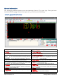
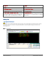
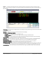
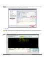
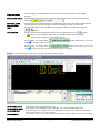
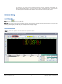
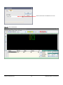
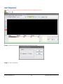
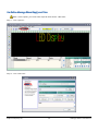
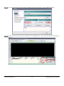
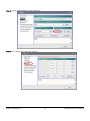
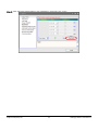
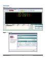
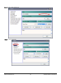
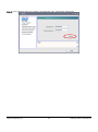
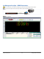
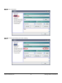
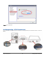
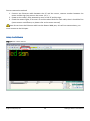
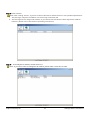
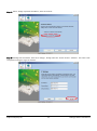
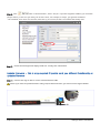
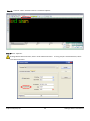
LED Displays
User Manual
V1.0
Spectra Displays Ltd
www.spectra-displays.co.uk
Index
GENERAL INFORMATION
Screen Layout and Overview
EDITING TEXT
Get System Information
Create Text
ADVANCED EDITING
Insert Bitmap File
Insert Real-Time Clock
Insert Countdown
Insert Temperature
Pre-Define Message Show Day(s) and Time
Pre-Define Power On/Off
Adjust Brightness
Set Password
Send Messages to Sign (RS232 Communication)
Send Messages to Group of Signs - 1(RS485
Communication)
Send Messages to Sign - 2 (TCP/IP Communication)
Set Up the Software
Update Firmware
©Spectra Displays Ltd
2
3
3
4
4
6
8
8
8
11
13
14
17
19
22
25
26
29
30
33
LED Signs Editor User Manual
General Information
The messaging software allows you to send messages from a PC to your sign. Once you have
installed the Messaging Software and opened it, you will see the following:
Screen Layout and Overview
D C
R Q O
K
A
P
B
M
E
F
J
G
H
I
AE
N
S
V
W
X
Y
Z
U
AB
A - Font: From five to 31 rows in height
E - Insert Bitmap: Insert graphics created in “Image
Edit”
F - Insert date/time: Insert real-time clock
G - Insert countdown: Insert countdown time and
date
H - Insert temperature: Insert temperature. Please
note; the display must have a temperature sensor to
use this mode
I - Insert variable: Insert variable
J - Insert symbol: Insert pre-defined symbols
K - Tool: Includes: “Xport Search”: Use to search for
or edit the IP address of the sign
M - About: Get information about this software
N - New Line: Click here to start a new line. Please
note; you must set this function under “Environment
Setup” in “Options”
V - Mode: 28 modes available
W - Speed: There are 5 speeds available
X - Stop Time: 10 stop times available
B - Colour: 12 colours available
C - Functions: Includes the following:
“Preview”; to preview the message on the sign
“Fonts”; you can select the font the message will be
displayed in
“Language”; you can select the language of software
“GPRS Admin”; used for GPRS communications
“Download Fonts”; 8 fonts available. Please note:
after updating firmware or creating new fonts with
this software, you must click on it to select it
D - Options: This allows you to set parameters, such as
communication mode, brightness, power on/off time,
password, screen number, etc.
O - Align: Options include: Align Left/Right/Centre
P - Download: This allows you to send your messages to
the sign
©Spectra Displays Ltd
AC AD
3
LED Signs Editor User Manual
Q - Save as: Save *.mld file created on this software
onto PC
R - Open: Open *.mld file created on this software
from PC
S - Messaging window: Type messages here
Y - Cycle: Defines how many times the message is
repeated
AB - Prior/Next record: To switch between message
files
AC - Insert/cancel record: Insert or delete message
files
AD - Post/cancel edit: Save or cancel the message
file onto the software
AE - Insert Extra Text: Allows you to show messages
in different fonts, it creates a bitmap from text you
enter, so you can use corporate fonts or extended
character sets
T - Align line: Allows you to see whether your
message is longer than the actual length of the sign
U - Start Show Time/End Show Time: Pre-define
message start and end time. Please note, you will need
to set up the “expand mode” under “Led mode” and “
play on time” under “ select play mode” in “Option”
Editing Text
Get System Information
NOTE: You can obtain information about your sign, such as pixel height and width, firmware versions
and model number etc., from the “Get System Information” tab of the option settings as outlined in the
following process.
Step 1 – Click ‘About’
©Spectra Displays Ltd
4
LED Signs Editor User Manual
Step 2 – To obtain information about the connection between the sign(s) and the PC, follow the steps
below. Start by clicking on ‘Options’. The options available are listed below along with a brief description of
their function.
Adjust Time – this allows you to adjust the time, for example you may wish the sign to be set to the same time
as that of your PC
Password – allows you to set your personal password for the display
LED state – advanced user options
LED Beep - beeps when you send a message, or not
Set Sign Number – this is used to set the sign number if the sign has RS485 comms
LED Mode - the base mode play all text while the expand mode plays text based on the time settings
Power ON/OFF – pre-define the power on/off time for your sign
Brightness – adjust the brightness of your sign. Please note: this option only works on ultrabright displays
Screen Number – use this to select a group of signs when you are using RS485 communications
Get System Information – gives information on the connection between the sign(s) and the PC
Setting User Information – Set the memo message when the sign is powered on
Environment Setup – various settings to control how the software functions, including settings to allows you
to continue your message on a new line by pressing ‘Enter’ on the keyboard, change LED colours etc
Communication – select the method of communication to the sign, e.g. RS232, RS485, TCP/IP, GSM, GPRS
©Spectra Displays Ltd
5
LED Signs Editor User Manual
Step 3 – select ‘Communication’ and ensure that the communication method selected is correct for your
display. Once you have done this, click on ‘Setup’ and then click ‘Close’.
Create Text
Note: Prior to creating your message, you should select “Download Fonts”. This only needs to be done
after updating the firmware or saving new fonts in the software.
Step 1 – Type your message into the editor window, for example the message “LED DISPLAY” is shown below.
©Spectra Displays Ltd
6
LED Signs Editor User Manual
Copy and paste:
Set font and colour:
You can copy content from Word or Excel documents and paste into the editor
window
Highlight the text, then set the font size and character colour using the drop down
Set mode, speed
and stop time:
Align:
options
and
Set the mode (how the message is revealed onto the screen), the speed (how fast the
reveal happens) and how long you want the message to stay on the screen
You can align the text to the right, left or justify the position of the text using the
buttons.
Add new line:
There are two options; either press enter on the keyboard or use the
button.
Note; prior to adding a new line, you should make a selection under
“Environment Options” in the “Setup” menu.
For example, you could select
click
, which means that, once you
a new line of text is formed.
Alternatively, you could select
click
which means that, even if you
in the software, no new lines are shown on the sign.
Step 2 – Click “Download” and select the appropriate download option
Download Current:
Download Variable:
Download Text:
Download All:
©Spectra Displays Ltd
Downloads the current message only
If you have used variables in your message, you can download these here.
If the message is text only, then select this option. Please note; symbols, countdown,
time, temperature etc. are all text items.
This option allows you to download text and bmp pictures from your PC to your sign.
7
LED Signs Editor User Manual
For pictures, you only need to download them once by selecting “Download All”.
When downloading again, you only need to select “Download Text” as the picture
has already been stored on the software and is viewed as text by the system.
Advanced Editing
Insert Bitmap File
Step 1 – Click
Open new BMP file
Step 2 – select the file you wish to display (keep in mind that the image is shown pixel for pixel, so if your sign
is only 7 pixels high, you will only see a small part of a larger image)
Insert Real-Time Clock
Step 1 – Click the ‘Options’ tab and select the ‘Options’ menu
©Spectra Displays Ltd
8
LED Signs Editor User Manual
Step 2 – Adjust the time and date as required. Then click “Download Time”. Finally, click on “Close”
Step 3 – Click
©Spectra Displays Ltd
9
LED Signs Editor User Manual
Step 4 - Select time format you require and then click “OK”.
Step 5 - Click “Download”
©Spectra Displays Ltd
10
LED Signs Editor User Manual
Insert Countdown
Step 1 - Click
Step 2 - Select countdown time or date format, then click “OK”
Select
when
to
start
the
countdown. Alternatively, you can
start to countdown from the
current time.
Select how long the countdown is to last
for.
©Spectra Displays Ltd
11
LED Signs Editor User Manual
Select when the countdown is to end.
Step 3 - Click “Download”
©Spectra Displays Ltd
12
LED Signs Editor User Manual
Insert Temperature
Note: This function only works on signs fitted with a temperature sensor
Step 1 - Click
Step 2 - Select the desired temperature format and then click “OK”
Step 3 - Click “Download”
©Spectra Displays Ltd
13
LED Signs Editor User Manual
Pre-Define Message Show Day(s) and Time
Note: In this option, you must select expand mode under “LED State”.
Step 1 - Click “Options”
Step 2 - Click “LED State”
©Spectra Displays Ltd
14
LED Signs Editor User Manual
Step 3 - Select “Play On Time” under “Select Play Mode”, then click “Setting”. Close “Options” window
Step 4 - Select the week(s) and days the message is to be displayed on. Then, select the times the message is
to be shown at.
©Spectra Displays Ltd
15
LED Signs Editor User Manual
Step 5 - Click
to set the start and end dates.
Step 6 - Click
to set the start and end times.
Step 7 - Click “Download”
©Spectra Displays Ltd
16
LED Signs Editor User Manual
Pre-Define Power On/Off
Note: In this option, you must select expand mode under “LED State”.
Step 1 - Click “Options”
Step 2 - Click “LED State”
©Spectra Displays Ltd
17
LED Signs Editor User Manual
Step 3 - Select “Expand Mode” under “LED Mode”
Step 4 - Click “Power ON/OFF”. Next, set the power on/off times you require, click on “Download ON/OFF”
and click “Close”. Finally click “Download”
©Spectra Displays Ltd
18
LED Signs Editor User Manual
Adjust Brightness
Note: This option is only available for Spectra’s ultrabright and outdoor LED displays. To adjust the
brightness you must select the “Expand Mode” under “LED State”.
Step 1 - Click “Options”
Step 2 - Click “LED State”
©Spectra Displays Ltd
19
LED Signs Editor User Manual
Step 3 - Select “Expand Mode”, under “LED State”
Step 4 - Click “Brightness”, then click “Setting”
©Spectra Displays Ltd
20
LED Signs Editor User Manual
Step 5 - After adjusting the brightness, click “Brightness” and finally click “Close”.
©Spectra Displays Ltd
21
LED Signs Editor User Manual
Set Password
Step 1 - Select “Options”
Step 2 - Click “LED State”
©Spectra Displays Ltd
22
LED Signs Editor User Manual
Step 3 - Click “Allow Password”
Step 4 - Click “Password”
©Spectra Displays Ltd
23
LED Signs Editor User Manual
Step 5 - Click password, then click “Setting” and then click “OK”. Finally click “Download”
©Spectra Displays Ltd
24
LED Signs Editor User Manual
Send Messages to Sign (RS232 Communication)
Connect the sign to the PC as per the image below:
©Spectra Displays Ltd
25
LED Signs Editor User Manual
Send Messages to Group Signs - 1 (RS485 Communication)
Note: In this instance, each sign in the group will receive the same message as all the others.
Step 1 – Connect the signs and set up the sign number as per the image shown below.
Step 2 – Click “Options”
©Spectra Displays Ltd
26
LED Signs Editor User Manual
Step 3 – Click “LED State”
Step 4 – Set the sign number, then click “Setting”
©Spectra Displays Ltd
27
LED Signs Editor User Manual
Step 5 – Click “Yes”
Step 6 - Click “CTRL+F3”. Make sure the sign is set for RS485 under the CTRL+F3 settings, if you do not know
what these settings should be, please contact Spectra immediately for assistance – altering these settings can
stop your sign from functioning correctly!
Step 7 – Once you have set the equipment number for every sign, you should connect the signs together. For
example: for two signs to be connected select the number of signs (2), then click “OK”. Please note: the same
protocol should be followed even when there are more than two signs.
Click “Download to All LED” if you want to send messages to all signs.
Once you choose a group, messages from the PC would be downloaded to the selected group of displays.
Prior to setting the “Screen Number”, you must set “Group number”. For example: if you want to display on
screen number 20, the first step is to set “Group 16-31” as display number 20 falls within this group.
©Spectra Displays Ltd
28
LED Signs Editor User Manual
Step 8 – Click “Download”
Send Messages to Sign - 2 (TCP/IP Communication)
Signs connection: For example: one PC, one Router, one led sign with X-port, two Ethernet cables. Connect as
below:
©Spectra Displays Ltd
29
LED Signs Editor User Manual
Correct connection method:
1. Connect one Ethernet cable between the PC and the router, connect another between the
router and the sign (any port on the router 1,2,3...)
2. Power on the router; once powered up turn on the PC and the sign.
3. Check the routers lights, if we one is lit and the other blinks for each cable, then it should be fine
(some routers are different, so please refer to the router manual)
Note: do not insert the Ethernet cable into the Router WAN port, this will not communicate, you
must connect to the LAN port.
Setup the Software
Step 1 – Click “XPort Search”
©Spectra Displays Ltd
30
LED Signs Editor User Manual
Step 2 – Click “Search”
Note: after clicking "Search”, if you are unable to find the IP address there are two possible explanations:
1. The LED sign, computer and Router are incorrectly connected, OR
2. The LED sign has no assigned IP address, so you should use the Router's DHCP dynamic IP address
function. (Please refer to the Router’s operating instructions).
Step 3 - To modify the IP address; double click on it.
Note: If you don’t want to change the IP address, please make a note of it for later.
©Spectra Displays Ltd
31
LED Signs Editor User Manual
Step 4 - Select “Assign a specific IP address”; then click “Next”
Step 5 - Modify the IP Address, then click “Assign”, finally close the “X-Port Search” window. You have now
completed setting the signs IP address.
©Spectra Displays Ltd
32
LED Signs Editor User Manual
Step 6 - Click
select” Communication", select "TCP/IP". Input the original IP address you recorded
(Step 3 above), or the one you have just set into "Host”, for example, at step 4, you got the IP address
"192.168.0.30", then enter it as shown, then click try to connect, if that is successful then finally "OK".
Step 7 - Check the messages and display mode etc. Finally click “Download”.
Update Firmware – This is only required if Spectra send you different functionality or
updated firmware
Step 1 - Connect the sign to the PC via the communication cable.
Note: If you want to update firmware using TCP/IP communication, you must connect sign to Router.
©Spectra Displays Ltd
33
LED Signs Editor User Manual
Step 2 - Click on “Tools” and then click on “Firmware Update”
Step 3 - Click “Options”
If using RS232 communication, select “Serial Communication”. If using TCP/IP communications, select
“TCP communication”.
©Spectra Displays Ltd
34
LED Signs Editor User Manual
Step 4 - Click “Browse” open new firmware
Step 4 - Click “Update”
©Spectra Displays Ltd
35
LED Signs Editor User Manual
Sign Settings
Please uses with caution, if you don’t know what the setting should be, then do not adjust this without
speaking to an engineer first. It is possible to stop your sign working by setting the wrong parameters. The
values already set can be read in the System Information control under Options.
Sign Settings – press Ctrl+F3 on the keyboard and the LED Parameter Setup box will appear (as shown
below):
Storage Location
Colour
Font Width
Remote Control
LED Width
Communication
SignLogo
Circle
Character Space
©Spectra Displays Ltd
If you update your messages frequently, select RAM (i.e. every few minutes). The RAM
option only stores the last message displayed. Alternatively, if you update your
messages infrequently and like to have all the messages you have used saved, then
select FLASH.
If your sign is tri-colour, you can show messages in tricolor (select TRICOLOUR) or in
mono-colour (select MONO-COLOUR). Please note: if your display is a mono-colour
product, it doesn’t matter which option you select as your messages will always
appear as a single colour.
If you choose EQUAL, each character will have the same width. If you select
VARIABLE, the character width will vary.
You can select whether to program the sign using the remote control if you wish to.
This option allows you to set the width of the display area of the sign.
When using a serial port, select RS232/TCP or RS485 according to the
communications type of your sign.
Displays a power on message when you turn the sign on.
This option allows you to cycle the message if you wish to.
This allows you to set the space between characters. The default space is one dot.
36
LED Signs Editor User Manual