1
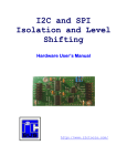
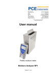
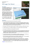
MDW-45
6617-2202
Converter
RS-232 – RS-422/485
www.westermo.com
© Westermo Teleindustri AB • 2005
User Guide
Safety
!
Before using this unit:
Read this manual completely and gather all information on the unit. Make sure
that you understand it fully. Check that your application does not exceed the safe
operating specifications for this unit.
Hazardous voltage may occur within this unit when connected to power supply
or TNV circuits.
Prevent access to hazardous voltage by disconnecting the unit from power supply
and all other electrical connections.
Prevent damage to internal electronics from electrostatic discharges (ESD) by
discharging your body to a grounding point (e.g. use of wrist strap).
!
Before installation:
This unit should only be installed by qualified personnel.
This unit should be built-in to an apparatus cabinet, or similar, where access is
restricted to service personnel only.
The power supply wiring must be sufficiently fused, and if necessary it must be
possible to disconnect manually from the power supply. Ensure compliance to
national installation regulations.
This unit uses convection cooling.To avoid obstructing the airflow around the unit,
follow the spacing recommendations (see Installation section).
Maintenance
No maintenance is required, as long as the unit is used as intended within the specified
conditions.
2
6617-2202
Introduction
The MDW-45 is an RS-422/485 to RS-232 converter.This device can be used in multidrop and point to point applications to connect devices like PCs, PLCs, drives and other
automation equipment.
In 2-wire half duplex applications (RS-485) the MDW-45 can automatically control the
state of the data bus based just on the data it receives.This allows the unit to be used
with equipment that has no handshaking signal.The maximum transmission rate possible
is 115.2 kbit/s.
RS-232
RS-422/485
TD LED
TD
3
3
RTS LED
RTS
CTS
4
S2:4
7
T+
T–
S2:3
CTS
LED
+5V
8
B
Bus termination
0V
B
MCU
DSR
6
+5V
B
Bus termination
+5V
S2:2
0V
B
RDŁ
LED
S2:1
RD
SG
2
5
S1:6
1
0VA
2
R+
R–
+5VA
0VA
Power
supply
6617-2202
F1
Isolated power supply
+5V
B
0VB
3
Field of application
Agency approvals and standards compliance
Type
EMC
Safety
Approval / Compliance
EN 61000-6-2
EN 55024
EN 61000-6-3
FCC part 15
EN 50121-4
IEC 62236-4
EN 60950
FCC Part 15.105 Notice:
4
Immunity industrial environments
Immunity IT equipment
Emission residential environments
Class B
Railway signalling and telecommunications apparatus
Railway signalling and telecommunications apparatus
IT equipment
This equipment has been tested and found to comply with
the limits for a Class B digital device, pursuant to Part 15 of
the FCC Rules.These limits are designed to provide reasonable protection against harmful interference in a residential
installation.This equipment generates, uses and can radiate
radio frequency energy and, if not installed and used in
accordance with the instructions, may cause harmful interference to radio communications. However, there is no
guarantee that interference will not occur in a particular
installation. If this equipment does cause harmful interference to radio or television reception, which can be determined by turning the equipment off and on, the user is
encouraged to try to correct the interference by one or
more of the following measures:
… Reorient or relocate the receiving antenna.
… Increase the separation between the equipment and
receiver.
… Connect the equipment into an outlet on a circuit
different from that to which the receiver is connected.
… Consult the dealer or an experienced radio/TV technician for help.
6617-2202
Declaration of Conformity
6617-2202
5
Type tests and environmental conditions
Electromagnetic Compatibility
Phenomena
Test
ESD
EN 61000-4-2
RF field AM modulated IEC 61000-4-3
RF field 900 MHz
Fast transient
ENV 50204
EN 61000-4-4
Surge
EN 61000-4-5
RF conducted
EN 61000-4-6
Magnetic field,
power freq.
Pulse Magnetic field
Voltage dips and
interruption
EN 61000-4-8
Description
Enclosure contact
Enclosure air
Enclosure
Enclosure
Signal ports
Power ports
Signal ports unbalanced
Signal ports balanced
Power ports
Signal ports
Power ports
Enclosure
EN 61000-4-9 Enclosure
EN 61000-4-11 AC power ports
Mains freq. 50 Hz
Mains freq. 50 Hz
Voltage dips
and interruption
EN 61000-4-16 Signal ports
SS 436 15 03
Signal ports
EN 61000-4-29 DC power ports
Radiated emission
EN 55022
FCC part 15
EN 55022
FCC part 15
EN 55022
Conducted emission
Dielectric strength
Environmental
Temperature
Humidity
Altitude
Service life
Vibration
Shock
Packaging
Phenomena
Enclosure
Dimension W x H x D
Weight
Degree of protection
Cooling
Mounting
6
IEC 60068-2-6
Enclosure
AC power ports
AC power ports
DC power ports
Signal port to all other
Power port to all other
Operating
Storage & Transport
Operating
Storage & Transport
Operating
Operating
Operating
IEC 60068-2-27 Operating
Test
UL 94
Description
PC / ABS
IEC 529
Enclosure
Level
± 6 kV
± 8 kV
10 V/m 80% AM (1 kHz), 80 – 1 000 MHz
20 V/m 80% AM (1 kHz), 800 – 960 MHz
20 V/m 80% AM (1 kHz), 1 400 – 2 000 MHz
20 V/m pulse modulated 200 Hz, 900 ± 5 MHz
± 2 kV
± 2 kV
± 2 kV line to earth, ± 2 kV line to line
± 2 kV line to earth, ± 1 kV line to line
± 2 kV line to earth, ± 2 kV line to line
10 V 80% AM (1 kHz), 0.15 – 80 MHz
10 V 80% AM (1 kHz), 0.15 – 80 MHz
100 A/m, 50 Hz, 16.7 Hz & 0 Hz
300 A/m, 6.4 / 16 ms pulse
10 & 5 000 ms, interruption
10 & 500 ms, 30% reduction
100 & 1 000 ms, 60% reduction
100 V 50 Hz
250 V 50 Hz
10 & 100 ms, interruption
10 ms, 30% reduction
10 ms, 60% reduction
+20% above & –20% below rated voltage
Class B
Class B
Class B
Class B
Class B
2 kVrms 50 Hz 1min
3 kVrms 50 Hz 1min
2 kVrms 50 Hz 1min (@ rated power < 60V)
–40 to +70°C
–40 to +70°C
5 to 95% relative humidity
5 to 95% relative humidity
2 000 m / 70 kPa
10 year
7.5 mm, 5 – 8 Hz
2 g, 8 – 500 Hz
15 g, 11 ms
Level
Flammability class V-1
35 x 121 x 119 mm
0.19 kg
IP 21
Convection
Horizontal on 35 mm DIN-rail
6617-2202
Interface specifications
Power
Rated voltage
MDW-45 LV
12 to 48 VDC
Operating voltage
9.6 to 57.6 VDC
Rated current
95 mA @ 12 VDC
35 mA @ 48 VDC
DC
Reverse polarity protected
Detachable screw terminal
0.2 – 2.5 mm2 (AWG 24-12)
Rated frequency
Polarity
Connection
Connector size
MDW-45 HV
95 to 240 VAC
110 to 250 VDC
85.5 to 264 VAC
88 to 300 VDC
21 mA @ 95 VAC
10 mA @ 110 VDC
48 – 62 Hz / DC
Polarity independent
Detachable screw terminal
0.2 – 2.5 mm2 (AWG 24-12)
RS-422/485
Electrical specification
Data rate
Data format
Connection
Connector size
Transmission range
Settings
Protection
RS-485
1 200 bit/s – 115.2 kbit/s
7 or 8 data bit, Odd, even or none parity, 1 or 2 stop bit
Detachable screw terminal
0.2 – 2.5 mm2 (AWG 24-12)
In accordance with EIA RS-485
≤1200 m, depending on data rate and cable type
120 Ω termination and failsafe biasing 680 Ω, by DIP-switch
Installation Fault Tolerant (up to ±60 V)
RS-232
Electrical specification
Data rate
Data format
Connection
Transmission range
6617-2202
RS-232
1 200 bit/s – 115.2 kbit/s
7 or 8 data bit, Odd, even or none parity, 1 or 2 stop bit
9-pin D-sub female DCE
15 m
7
Mounting
This unit should be mounted on 35 mm DIN-rail, which is
horizontally mounted inside an apparatus cabinet, or similar.
Snap on mounting, see figure.
CLICK!
Cooling
This unit uses convection cooling.To avoid obstructing the airflow around the unit, use the following spacing rules. Minimum
spacing 25 mm (1.0 inch) above /below and 10 mm (0.4 inches)
left /right the unit. Spacing is recommended for the use of unit
in full operating temperature range and service life.
10 mm *
(0.4 inches)
25 mm
* Spacing (left/right) recommended
for full operating temperature range
25 mm
Removal
Press down the black support at the top of the unit. See figure.
LED Indicators
LED
PWR
TD
RD
RTS
CTS
8
Status
ON
OFF
ON
OFF
ON
OFF
ON
OFF
ON
OFF
Description
In service
Out of service
Transmitted Data: Displays data received from the local RS-232 port
No data
Received Data: Displays data leaving the modem on the RS-232 port
No data
Status of RTS from the RS-232 interface
No RTS
Status of CTS from the RS-232 interface
No CTS
6617-2202
Connections
S1 DIP-switch under lid
(for details see page 10)
LED indicators
(for details see page 8)
S2 DIP-switch
Termination
(for details see page 11)
RS-422/485 interface
screw terminal
4-position Direction*
No. 1
In
No. 2
In
No. 3
In/Out
No. 4
In/Out
Description
R+
line RS-422
R–
line RS-422
T+
line RS-422/485
T–
line RS-422/485
Power connection, LV
screw terminal
2-position
No. 1
No. 2
Description
0 VDC
12 – 48 VDC
Power connection, HV
screw terminal
2-position Description Product marking
No. 1
AC: Neutral
DC: –Voltage N/–
No. 2
AC: Line
DC: +Voltage L/+
RS-232 (DCE)
9-position Direction Description
No. 1
–
No. 2
Out
Received Data (RD)
No. 3
In
Transmitted Data (TD)
No. 4
–
No. 5
–
Signal Ground (SG)
No. 6
Out
Data Set Ready (DSR)
No. 7
In
Request To Send (RTS)
No. 8
Out
Clear To Send (CTS)
No. 9
–
6617-2202
Railway installation
close to the rails
(RS-232, RS-422/485)
For a cable located inside 3 m boundary and
connected to this port, the use of shielded
cable is recommended, this to minimize the
risk of interference.The cable shield should
be properly connected (360°) to an earthing
point within 1 m from this port.This earthing point should have a low impedance connection to the conductive enclosure of the
apparatus cabinet, or similar, where the unit
is built-in.This conductive enclosure should
be connected to the earthing system of an
installation and may be directly connected
to the protective earth.
9
DIP-switch settings
Before DIP-switch settings:
!
Prevent damage to internal electronics from electrostatic discharges (ESD)
by discharging your body to a grounding point (e.g. use of wrist strap).
S1
Selection of data format
Selection of data rate
ON
S1
ON
1200 bit/s
S1
1 2 3 4 5 6 7 8
ON
S1
ON
2400 bit/s
S1
1 2 3 4 5 6 7 8
ON
4800 bit/s
S1
1 2 3 4 5 6 7 8
11 bit format*
1 2 3 4 5 6 7 8
ON
S1
10 bit format*
1 2 3 4 5 6 7 8
ON
S1
9 bit format*
1 2 3 4 5 6 7 8
ON
9600 bit/s
S1
1 2 3 4 5 6 7 8
12 bit format*
1 2 3 4 5 6 7 8
ON
S1
19.2 kbit/s
Supervision table when selecting data format
1 2 3 4 5 6 7 8
7 bit
ON
S1
38.4 kbit/s
1 2 3 4 5 6 7 8
No parity
Parity
ON
S1
8 bit
57.6 kbit/s
1 stop bit
1 2 3 4 5 6 7 8
2 stop bit
ON
S1
115.2 kbit/s
Number of bit
ON
10
10
11
11
11
12
ON
2-wire RS-485
S1
1 2 3 4 5 6 7 8
Data control
1 2 3 4 5 6 7 8
ON
ON
4-wire RS-422
S1
1 2 3 4 5 6 7 8
In RTS-control and Transmitter always active.The
switches for data rate and number of bits has no
effects.
10
10
Selection of bus control
Selection of bus format
S1
9
* See Supervision table when selecting data bits.
Turning time 1 – 1.5 bit time
1 2 3 4 5 6 7 8
S1
• • • •
• • • •
• • • •
• • • •
•
• • •
•
• • •
RTS-control
1 2 3 4 5 6 7 8
ON
S1
1 2 3 4 5 6 7 8
Transmitter
always active
6617-2202
S2 Below panel, RS-422/485 termination
ON
No termination and fail-safe
1 2 3 4
ON
Termination with fail-safe (2-wire)
1 2 3 4
ON
Termination with fail-safe (4-wire)
1 2 3 4
Note! DIP-switch alterations are only effective after a power on.
Factory settings
S1
ON
1 2 3 4 5 6 7 8
6617-2202
Data rate – 9600 bit/s, data format – 10 bit
Bus format, 2-wire
Note: Switch 1:8 is not used
ON
S2
1 2 3 4
No termination
and fail-safe
11
Unit specific description
When the converter is set to data-control mode the transmitter is activated by data on
TD (RS-232).The time the transmitter stays active corresponds to one character-time
plus the turning time for the set data rate and number of bits. If more data arrives on
TD before the turning time has expired the transmitter stays active for an additional
one character time and so on. In RTS-control mode the transmitter is activated by the
RS-232 RTS-signal. In this mode the dip-switches for data rate and number of bits have
no effect.The LED indicators show the status of the data signals.The fail-safe termination
ensures that the signal level at the receiver is in ‘mark state’ (differential>0.2 Volts) when
there is no data on the RS-485 bus. Full duplex is only possible if 4-wires are used.
Field of application
RS-422 and RS-485 were both designed for multidrop applications.When a system is
installed it should always form a bus structure (see diagrams). Star shaped networks
should never be created; there are other Westermo products that can be used to create
star net applications.To install a system according to the RS-422/485 specification it is
very important that the line is terminated at the correct points.The recommendation is
to terminate the receiver on the master unit and the final bus slave unit. See diagrams for
details of how this is done with RS-485 (2-wire) and RS-422 (4-wire).
Max 1 200 metres
T+
T–
Max 0.3 metre
T– T+
T– T+
=Termination
T– T+
Max 32 connections
R+
R–
T+
T–
R– R+ T– T+ R– R+ T– T+
=Termination
R– R+ T– T+
Max 32 connections
N.B. R+/R–,T+/T– definitions are not standard, it can help to shift + and –
if the unit does not work.
12
6617-2202
Line connection
4-wire
2-wire
MDW-45
Receiver
RS-422/485
equipment
Twisted pairs
1
R+
T+
R–
T–
2
Transmitter
Twisted pairs
3
Transmitter
4
T+
R+
T–
R–
RS-422/485
equipment
MDW-45
Receiver
3
Transmitter/ T+/R+
Receiver 4
T–/R–
T+/R+ Transmitter/
Receiver
T–/R–
*) If shielded cable is used, connect the shield only at one end to avoid ground currents.
Care recommendations
Follow the care recommendations below to maintain full operation of unit and to fulfil
the warranty obligations.
… This unit must not be operating with removed covers or lids.
… Do not attempt to disassemble the unit.
… There are no user serviceable parts inside.
… Do not drop, knock or shake the unit, rough handling above the specification may
cause damage to internal circuit boards.
… Do not use harsh chemicals, cleaning solvents or strong detergents to clean the
unit.
… Do not paint the unit. Paint can clog the unit and prevent proper operation.
… Do not expose the unit to any kind of liquids (rain, beverages, etc).
The unit is not waterproof. Keep the unit within the specified humidity levels.
… Do not use or store the unit in dusty, dirty areas, connectors as well as other
mechanical part may be damaged.
If the unit is not working properly, contact the place of purchase, nearest Westermo
distributor office or Westermo Tech support.
6617-2202
13
Application example
RS-232
RS-422/485
RS-232
RS-232
RS-232
Subsidiaries
Westermo Data Communications Ltd
Talisman Business Centre • Duncan Road
Park Gate, Southampton • SO31 7GA
Phone: +44(0)1489 580 585 • Fax.:+44(0)1489 580586
E-Mail: [email protected]
Westermo Data Communications GmbH
Goethestraße 67, 68753 Waghäusel
Tel.: +49(0)7254-95400-0 • Fax.:+49(0)7254-95400-9
E-Mail: [email protected]
Westermo Data Communications S.A.R.L.
9 Chemin de Chilly 91160 CHAMPLAN
Tél : +33 1 69 10 21 00 • Fax : +33 1 69 10 21 01
E-mail : [email protected]
Westermo Teleindustri AB have distributors in several
countries, contact us for further information.
REV.A • 6617-2202
Westermo Teleindustri AB • SE-640 40 Stora Sundby, Sweden
Phone +46 16 42 80 00 Fax +46 16 42 80 01
E-mail: [email protected]
Westermo Web site: www.westermo.com
05.03 Mälartryck AB, Eskilstuna, Sweden
RS-232