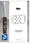
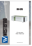
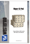
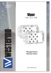
1
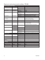
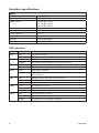
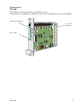
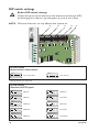
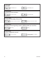
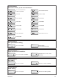
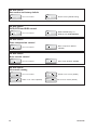
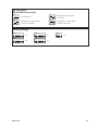
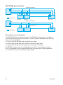
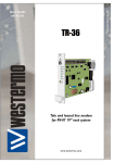
6614-2210
TR-36B
Tele and leased line modem
for RV-07 19” rack system
www.westermo.com
© Westermo Teleindustri AB
User Guide
Legal information
The contents of this document are provided “as is”. Except as required by applicable
law, no warranties of any kind, either express or implied, including, but not limited to,
the implied warranties of merchantability and fitness for a particular purpose, are made
in relation to the accuracy and reliability or contents of this document. Westermo
reserves the right to revise this document or withdraw it at any time without prior
notice.
Under no circumstances shall Westermo be responsible for any loss of data or income
or any special, incidental, and consequential or indirect damages howsoever caused.
More information about Westermo can be found at the following Internet address:
http://www.westermo.com
2
6614-2210
Safety
!
!
Before installation:
Read this manual completely and gather all information on the unit. Make sure that
you understand it fully. Check that your application does not exceed the safe operating specifications for this unit.
This unit should only be installed by qualified personnel.
This unit should be built-in to an apparatus cabinet, or similar, where access is
restricted to service personnel only.
The power supply wiring must be sufficiently fused, and if necessary it must be
possible to disconnect manually from the power supply. Ensure compliance to
national installation regulations.
This unit uses convection cooling. To avoid obstructing the airflow around the unit,
follow the spacing recommendations (see Cooling section).
Before mounting, using or removing this unit:
Prevent access to hazardous voltage by disconnecting the unit from power supply
and all other electrical connections.
Warning! Do not open connected unit. Hazardous voltage may occur within this
unit when connected to power supply or TNV circuits.
Care recommendations
Follow the care recommendations below to maintain full operation of unit and to
fulfil the warranty obligations.
This unit must not be operating with removed covers or lids.
Do not attempt to disassemble the unit. There are no user serviceable parts inside.
Do not drop, knock or shake the unit, rough handling above the specification may cause
damage to internal circuit boards.
Do not use harsh chemicals, cleaning solvents or strong detergents to clean the unit.
Do not paint the unit. Paint can clog the unit and prevent proper operation.
Do not expose the unit to any kind of liquids (rain, beverages, etc). The unit is not waterproof. Keep the unit within the specified humidity levels.
Do not use or store the unit in dusty, dirty areas, connectors as well as other mechanical
part may be damaged.
If the unit is not working properly, contact the place of purchase, nearest Westermo distributor office or Westermo Tech support.
Maintenance
No maintenance is required, as long as the unit is used as intended within the specified
conditions.
6614-2210
3
Agency approvals and standards compliance, TR-36B
Type
EMC
Safety
Approved
Agency/ W-mo
W-mo
EN 61000-6-2, Immunity industrial environments
W-mo
EN 55024, Immunity IT equipment
W-mo
EN 61000-6-4, Emission industrial environments
W-mo
FCC part 15 Class A
W-mo
EN 50121-4, Railway signalling and telecommunications apparatus
W-mo
IEC 62236-4, Railway signalling and telecommunications apparatus
W-mo
EN 60950-1, IT equipment
PSTN
FCC Part 15.105 Notice:
4
Approval / Compliance
ETSI TS103 021-1, ETSI TS103 021-2, ETSI TS103 021-3
This equipment has been tested and found to comply with the limits for a
Class A digital device, pursuant to Part 15 of the FCC Rules. These limits
are designed to provide reasonable protection against harmful interference
in a industrial installation. This equipment generates, uses and can radiate
radio frequency energy and, if not installed and used in accordance with
the instructions, may cause harmful interference to radio communications.
However, there is no guarantee that interference will not occur in a particular installation. If this equipment does cause harmful interference to radio
or television reception, which can be determined by turning the equipment
off and on, the user is encouraged to try to correct the interference by
one or more of the following measures:
… Reorient or relocate the receiving antenna
… Increase the separation between the equipment and receiver
… Connect the equipment into an outlet on a circuit different from that to
which the receiver is connected
… Consult the dealer or an experienced radio/TV technician for help.
6614-2210
Declaration of Conformity
Westermo Teleindustri AB
Declaration of conformity
The manufacturer
Westermo Teleindustri AB
SE-640 40 Stora Sundby, Sweden
Herewith declares that the product(s)
Type of product
Model
Art no
Rack mounted Tele and Leased Line modem
TR-36B
3614-0510
is in conformity with the following EC directive(s).
No
Short name
2004/108/EC
1999/5/EC
Electromagnetic Compatibility (EMC)
Radio and telecommunications terminal equipment (R&TTE)
References of standards applied for this EC declaration of conformity.
No
Title
Issue
EN 61000-6-2
EN 61000-6-4
EN 50121-4
Immunity for industrial environments
Emission standard for industrial environments.
Railway applications – Electromagnetic compatibility
– Emission and Immunity of the signalling and
telecommunications apparatus
Railway signalling and telecommunications apparatus
Information technology equipment – Immunity
2005
2007
2006
IEC 62236-4
EN 55024
The last two digits of the year in which the CE marking was affixed:
2003
1998
+ A1:2001
+ A2:2003
08
Pierre Öberg
R&D Manager
14th October 2008
Postadress/Postal address
Tel.
Telefax
Postgiro
Bankgiro
Org.nr/
Corp. identity number
Registered office
S-640 40 Stora Sundby
Sweden
016-428000
Int+46 16428000
016-428001
Int+46 16428001
52 72 79-4
5671-5550
556361-2604
Eskilstuna
6614-2210
5
Type tests and environmental conditions, TR-36B
Electromagnetic Compatibility
Phenomena
Test
ESD
EN 61000-4-2
RF conducted
EN 61000-4-6
Voltage dips and
interruption
EN 61000-4-11
Description
Enclosure contact
Enclosure air
Enclosure
Signal ports
Power ports
Signal ports
unbalanced
Signal ports balanced
Power ports
Signal ports
Power ports
AC power ports
Mains freq. 50 Hz
Mains freq. 50 Hz
Voltage dips and
interruption
EN 61000-4-16
SS 436 15 03
EN 61000-4-29
Signal ports
Signal ports
DC power ports
Radiated emission
EN 55022
FCC part 15
EN 55022
FCC part 15
EN 55022
EN 60950
Enclosure
RF field AM modulated
Fast transient
IEC 61000-4-3
EN 61000-4-4
Surge
EN 61000-4-5
Conducted emission
Dielectric strength
Environmental
Temperature
Humidity
Altitude
Reliability prediction
(MTBF)
Service life
Packaging
Dimension W x H x D
Weight
Degree of protection
Cooling
Mounting
6
MIL C217F2
IEC 529
AC power ports
AC power ports
DC power ports
Signal port to other
isolated ports
Power port to other
isolated ports
Test levels
± 6 kV
± 8 kV
20 V/m 80% AM (1 kHz), 80 – 2 700 MHz
± 2 kV
± 2 kV
± 2 kV line to earth, ± 2 kV line to line
± 2 kV line to earth, ± 1 kV line to line
± 2 kV line to earth, ± 2 kV line to line
10 V 80% AM (1 kHz), 0.15 – 80 MHz
10 V 80% AM (1 kHz), 0.15 – 80 MHz
10 & 5 000 ms, interruption
10 & 500 ms, 30% reduction
100 & 1 000 ms, 60% reduction
100 V 50 Hz line to earth
250 V 50 Hz line to line
10 & 100 ms, interruption
10 ms, 30% reduction
10 ms, 60% reduction
+20% above & –20% below rated voltage
Class A
Class A
Class B
Class B
Class B
2 kVrms 50 Hz 1 min
3 kVrms 50 Hz 1 min
2 kVrms 50 Hz 1 min (@ rated power <60 V)
Operating
Storage & Transport
Operating
Storage & Transport
Operating
Operating
-40 to +70ºC
–40 to +70ºC
5 to 95% relative humidity.
5 to 95% relative humidity.
2 000 m / 70 kPa
676000 h @ 25ºC
Operating
10 year
Enclosure
20 x 100 x 175 mm
0.14 kg
IP 20
Convection
RV07B 19” rack
6614-2210
Description
The TR-36B is a rack mount analogue V.34 PSTN and 2- or 4-wire leased line modem.
It supports data rates of up to 115.2 kbit/s on the terminal side and modem modulation
speeds of up to 33.6 kbit/s on the line side. The modem is designed to harsh industrial
standards for applications where a number of modems are required in the same location. The unit has passed extensive approvals testing by both Westermo and external test
houses, showing the modem can operate in environments with a high level of electromagnetic interference.
The TR-36B features a number of security functions such as password protection, dialback security and caller ID answering making the modem ideal for critical industrial applications. The TR-36B can also be remotely configured making it ideal for use in unmanned
installations.
The modem is designed to be prepared for unexpected faults. The modem is equipped
with transient protection on the line side and a watchdog function that monitors and
automatically resets the modem in the event of a fault. In case of a leased line failure, a
PSTN dial backup facility can be configured for additional reliability.
The TR-36 is configurable via its serial interface using standard terminal emulation software using Hayes AT commands or the Westermo TD-Tool modem configuration utility.
Additionally many functions of the TR-36B can be configured via the onboard
DIP-switches.
The modem is designed for use in the Westermo RV-07B 19" rack, which can hold up to
16 cards as well as two PS-20 power supplies. The modems slide into the chassis from
the front with all line connections terminating onto the backplane. The rack can hold up
to 16 TR-36B modems and can also be externally powered by a 24 V supply.
… Data rate up to 33.6 kbit/s with
Fast Connect
… Terminal rate up to 115.2 kbit/s
… 2- and 4-wire leased line
… V.23 HDX with multidrop
… DTR and incoming data dialling
… DIP-switch configuration
… Watchdog
… Secure call back and access
… Industrial environment transient
protection on all interfaces
6614-2210
… Up to 11 bits
… Tri-Galvanic isolation
(interface/line/supply)
… Caller ID presentation
and answering
… Remote configuration
… RS-422 / RS-485 interface
… Dial backup for PSTN
and Leased Line
7
Interface specifications
Power
Rated voltage
Operating voltage
Rated current
Rated frequency
Power consumption
Inrush current l2t
Startup current
Polarity
Connection
12 to 48 VDC
10 to 60 VDC
130 mA @ 12 VDC
63 mA @ 24 VDC
40 mA @ 48 VDC
DC
2W
6 mA2 S
0.22 Apeak
Polarity dependent
32-pin Europe connector
LED indicators
LED
RTS
RD
TD
DCD
REL
LINE
PWR
8
Status
OFF
ON
OFF
FLASH
OFF
FLASH
OFF
ON
OFF
ON
FLASH
OFF
ON
FLASH
OFF
ON
FLASH
Indication of
RTS signal is inactive
RTS signal is active
No data
The modem transmitting data on the DTE interface
No data
The modem receiving data on the DTE interface
DCD signal is inactive
DCD signal is active, modem has detected a carrier or the signal is
set to always on
Reliable mode is off, direct or normal mode
Reliable mode is on
Reliable mode with error correction and compression
The modem is on-hook
The modem is off-hook with a established connection
Line backup interface in use
The modem has no power
The modem is up and running
The modem is in the power-on selftest
6614-2210
Connections
TR-36B
TR-36B have 1 Europe connector angled 32-pin male.
The connector has Westermo specific pin-out and is intended to be insert into RV-07B.
LED Status Indicators
32-pin male
connector
Jack socket
6614-2210
9
DIP-switch settings
!
NOTE
Before DIP-switch settings:
Prevent damage to internal electronics from electrostatic discharges (ESD)
by discharging your body to a grounding point (e.g. use of wrist strap).
DIP-switch alterations are only effective after a power on.
S1
S2
S3
S4
S5
S1 DIP-switch
Stored values / Auto detect
ON
ON
Use stored values
1 2 3 4 5 6 7 8
Auto detect*
1 2 3 4 5 6 7 8
* 300 and 600 bit/s not supported
S1 DIP-switch
Selection of DTE speed
ON
ON
300 bit/s
1 2 3 4 5 6 7 8
9600 bit/s
1 2 3 4 5 6 7 8
ON
ON
600 bit/s
1 2 3 4 5 6 7 8
19.2 kbit/s
1 2 3 4 5 6 7 8
ON
ON
1200 bit/s
1 2 3 4 5 6 7 8
38.4 kbit/s
1 2 3 4 5 6 7 8
ON
ON
2400 bit/s
1 2 3 4 5 6 7 8
57.6 kbit/s
1 2 3 4 5 6 7 8
ON
ON
4800 bit/s
1 2 3 4 5 6 7 8
10
115.2 kbit/s
1 2 3 4 5 6 7 8
6614-2210
S1 DIP-switch
Selection of DTE format
ON
ON
7E 1S
1 2 3 4 5 6 7 8
7N 2S
1 2 3 4 5 6 7 8
ON
ON
7O 1S
1 2 3 4 5 6 7 8
7E 2S
1 2 3 4 5 6 7 8
ON
ON
8N 1S
1 2 3 4 5 6 7 8
7O 2S
1 2 3 4 5 6 7 8
ON
ON
8E 1S
1 2 3 4 5 6 7 8
8N 2S
1 2 3 4 5 6 7 8
ON
ON
8O 1S
1 2 3 4 5 6 7 8
ON
1 2 3 4 5 6 7 8
ON
1 2 3 4 5 6 7 8
8E 2S
1 2 3 4 5 6 7 8
Direct mode 8E1 or 8O1
8O1 in command mode
ON
8O 2S
1 2 3 4 5 6 7 8
Direct mode 7E1 or 7O1
8N1 in command mode
S2 DIP-switch
Leased Line Mode selection
ON
1 2 3 4 5 6 7 8
ON
1 2 3 4 5 6 7 8
Leased line disable,
PSTN enable
ON
Leased line V.23 multidrop
For V.23 Multidrop settings,
see selection below.
ON
Leased line answering
1 2 3 4 5 6 7 8
Leased line calling
1 2 3 4 5 6 7 8
S2 DIP-switch
DTE interface Selection
ON
1 2 3 4 5 6 7 8
6614-2210
RS-422/485 disable,
RS-232 enable
ON
1 2 3 4 5 6 7 8
RS-422/485 enable,
RS-232 disable
11
S2 DIP-switch
RS-422/485
ON
ON
RS-422/485, 2-wire
1 2 3 4 5 6 7 8
RS-422/485, 4-wire
1 2 3 4 5 6 7 8
S2 DIP-switch
Leased line 2/4 wire selection
ON
ON
Leased line 2-wire
1 2 3 4 5 6 7 8
Leased line 4-wire
1 2 3 4 5 6 7 8
S2 DIP-switch
Selection PSTN backup of Leased line
ON
ON
Backup of leased line disabled
1 2 3 4 5 6 7 8
Backup of leased line enabled
1 2 3 4 5 6 7 8
S2 DIP-switch
Selection of answering/calling mode for PSTN backed up Leased Line
ON
ON
Answering
1 2 3 4 5 6 7 8
Calling
1 2 3 4 5 6 7 8
S2 DIP-switch
Remote configuration control
ON
ON
Use stored values
1 2 3 4 5 6 7 8
12
1 2 3 4 5 6 7 8
Remote configuration disabled
(AT*WRCA=0)
6614-2210
S3 DIP-switch
Selection of line speed and modulation
ON
1 2 3 4 5 6 7 8
Use saved parameters
defined by AT+MS
ON
ON
Auto V.32bis V32/V34
1 2 3 4 5 6 7 8
ON
V.21 300
1 2 3 4 5 6 7 8
V.32bis 14400
1 2 3 4 5 6 7 8
ON
ON
V.23 1200 hdx
1 2 3 4 5 6 7 8
V.34 19200
1 2 3 4 5 6 7 8
ON
ON
V.22 1200
1 2 3 4 5 6 7 8
V.34 24000
1 2 3 4 5 6 7 8
ON
ON
V.22bis 2400
1 2 3 4 5 6 7 8
V.34 28 800
1 2 3 4 5 6 7 8
ON
ON
V.32bis 4800
1 2 3 4 5 6 7 8
V.34 33600
1 2 3 4 5 6 7 8
ON
ON
Auto V.32/V32bis
1 2 3 4 5 6 7 8
Automatic line speed
1 2 3 4 5 6 7 8
ON
V.32bis 9600
1 2 3 4 5 6 7 8
S3 DIP-switch
PLC parameter setting
ON
ON
Use stored values
1 2 3 4 5 6 7 8
1 2 3 4 5 6 7 8
PLC settings
(ATQ1E0&C1&K0&A1)
S3 DIP-switch
Flow control DTE interface
ON
ON
Use stored value for AT&Kn
1 2 3 4 5 6 7 8
1 2 3 4 5 6 7 8
RTS/CTS flow control enable
(AT&K3)
S3 DIP-switch
Dial abort
ON
ON
Use stored values
1 2 3 4 5 6 7 8
Dial abort disabled (AT&A1)
1 2 3 4 5 6 7 8
S3 DIP-switch
Blind dialing
ON
ON
Use stored values
1 2 3 4 5 6 7 8
6614-2210
Enable blind dialling (ATX3)
1 2 3 4 5 6 7 8
13
S4 DIP-switch
Set modem to factory default
ON
ON
Use stored values
1 2 3 4 5 6 7 8
Restore factory default setting*
1 2 3 4 5 6 7 8
Don’t leave S4:1 in ON position if not intended to restore factory setting at every power on.
S4 DIP-switch
DCD, DTR and DSR control
ON
ON
Use stored values
1 2 3 4 5 6 7 8
1 2 3 4 5 6 7 8
DCD and DSR always on,
DTR ignored (AT&C0&D0&S0)
S4 DIP-switch
Data compression control
ON
ON
Use stored values
1 2 3 4 5 6 7 8
1 2 3 4 5 6 7 8
Data compression disabled
(AT%C0)
S4 DIP-switch
Auto retrain control
ON
ON
Use stored values
1 2 3 4 5 6 7 8
Auto retrain disabled (AT%E0)
1 2 3 4 5 6 7 8
S4 DIP-switch
Line mode setting
ON
ON
Use stored values
1 2 3 4 5 6 7 8
Reliable mode enable (AT\N2)
1 2 3 4 5 6 7 8
ON
ON
Buffer mode enabled (AT\N0)
1 2 3 4 5 6 7 8
14
Direct Mode enabled (AT\N1)
1 2 3 4 5 6 7 8
6614-2210
S5 DIP-switch
RS-422/485 termination
ON
ON
No termination
1 2 3 4
ON
1 2 3 4
1 2 3 4
ON
Termination of both T and R
in 2-wire connection
1 2 3 4
Termination of R in 4-wire
connection
Termination of both T and R
in 4-wire connection
Factory settings
ON
ON
S1
1 2 3 4 5 6 7 8
1 2 3 4 5 6 7 8
ON
6614-2210
S5
1 2 3 4
ON
S2
1 2 3 4 5 6 7 8
ON
S3
S4
1 2 3 4 5 6 7 8
15
V.23 2- / 4-wire HDX- / FDX-leased line settings
S1 DIP-switch
Selection of DTE speed
ON
1200 bit/s
1 2 3 4 5 6 7 8
S1 DIP-switch
Selection of DTE-format
ON
1 2 3 4 5 6 7 8
8E1, 8O1,
8O1 in command mode
ON
1 2 3 4 5 6 7 8
7E1, 7O1, 8N1,
8N1 in command mode
S2 DIP-switch
Leased line mode selection
ON
1200 bit/s leased line /mulidrop
1 2 3 4 5 6 7 8
S2 DIP-switch
Leased line 2/4-wire selection
ON
ON
2-wire leased line
1 2 3 4 5 6 7 8
4-wire leased line
1 2 3 4 5 6 7 8
S3 DIP-switch
V.23 line modulation
ON
V.23 1200 HDX/FDX
1 2 3 4 5 6 7 8
S3 DIP-switch
Carrier active using RTS or incoming data
ON
ON
Incoming data
1 2 3 4 5 6 7 8
RTS controlled
1 2 3 4 5 6 7 8
S4 DIP-switch
Permanent carrier control
ON
ON
Disabled
1 2 3 4 5 6 7 8
16
Enabled
1 2 3 4 5 6 7 8
6614-2210
Termination recommandations of Leased lines
and Dial-up connections
In some connections the communication line (Leased Line or PSTN) must be
terminated. The table below shows the right way to activate the termination
for different usages. As a standard, the receiver in multidrop systems at the end
points shall be terminated.
S4 DIP-switch
Termination recomendations for TR-36B
ON
ON
Multidrop
1 2 3 4 5 6 7 8
V23 2-wire – endunit
PSTN
1 2 3 4 5 6 7 8
ON
PSTN
ON
Multidrop
1 2 3 4 5 6 7 8
Backup
1 2 3 4 5 6 7 8
V23 2-wire – dropunit
ON
2-wire
ON
Multidrop
1 2 3 4 5 6 7 8
Leased Line
1 2 3 4 5 6 7 8
V23 4-wire – endunit
ON
4-wire
ON
Multidrop
1 2 3 4 5 6 7 8
Leased Line
1 2 3 4 5 6 7 8
V23 4-wire – dropunit
6614-2210
17
RS-422/485 general advice
4-wire termination
R+
R–
T+
T–
R– R+ T– T+ R– R+ T– T+
TR-36 485
B’ A’ B
A
=Termination
Slave unit
Slave unit
Slave unit
2-wire termination
T+
T–
Max 0.3 metre
TR-36 485
T- T+
T- T+
B
A
=Termination
Slave unit
Slave unit
Slave unit
Termination recommendations
The RS-422/485 line must be terminated. In the TR-36B, the termination is combined
with fail-safe functionality. The termination is used to prevent undefined states when the
bus is in tri-state condition.
… Using 2-wire RS-485 both ends should be terminated.
… Using 4-wire RS-485 both pairs shall be terminated at both ends.
… Using 4-wire RS-422 it’s only necessary to terminate the receivers.
RS-422/485 connection pins can be differently named. For some equipment brands
the T+ corresponds to A, but other brands might use some other naming convention.
If a unit does not work it can help to swap A and B.
18
6614-2210
Mounting /Removal
Before mounting or removing the unit:
Make sure that the RV-07B modem rack
has been installed according to
instructions.
Mounting
The TR-36 is designed to fit
into the RV-07B rack. The
modem is installed by sliding
the card along the slot guides.
Ensure the card is the correct way up, the handle will be at
the
bottom of the card. Press firmly but carefully until full connection between the modems
32 pin male connector and the connector on the backplane is achieved.
To ensure proper galvanic connection between front panels, do not leave empty slots
between modems. Always add modems from one side in the rac
6614-2210
19
Westermo Teleindustri AB • SE-640 40 Stora Sundby, Sweden
Phone +46 16 42 80 00 Fax +46 16 42 80 01
E-mail: [email protected]
Westermo Web site: www.westermo.com
Westermo Data Communications AB
SE-724 81 Västerås
Phone: +46 (0)16 42 80 00 • Fax: +46 (0)21 35 18 50
[email protected]
Westermo Data Communications S.A.R.L.
9 Chemin de Chilly 91160 CHAMPLAN
Tél : +33 1 69 10 21 00 • Fax : +33 1 69 10 21 01
E-mail : [email protected]
Westermo Data Communications Ltd
Talisman Business Centre • Duncan Road
Park Gate, Southampton • SO31 7GA
Phone: +44(0)1489 580-585 • Fax.:+44(0)1489 580586
E-Mail: [email protected]
Westermo Data Communications Pte Ltd
2 Soon Wing Road #08-05
Soon Wing Industrial Building
Singapore 347893
Phone +65 6743 9801 • Fax +65 6745 0670
E-mail: [email protected]
Westermo Data Communications GmbH
Goethestraße 67, 68753 Waghäusel
Tel.: +49(0)7254-95400-0 • Fax.:+49(0)7254-95400-9
E-Mail: [email protected]
Westermo Teleindustri AB have distributors in several countries, contact us for further information.
REV.A 6614-2210 2008.09 Mälartryck AB, Eskilstuna, Sweden
Subsidiaries