1
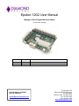
Epsilon-12G2 User Manual
Managed 14-Port Gigabit Ethernet Switch
Part Number 7460440
Revision
Date
A.00
11/27/2013
Initial release
A.01
9/3/2014
Minor update
FOR TECHNICAL SUPPORT
PLEASE CONTACT:
[email protected]
Comment
Copyright 2014
Diamond Systems Corporation
555 Ellis Street
Mountain View, CA 94043 USA
Tel 1-650-810-2500
Fax 1-650-810-2525
www.diamondsystems.com
CONTENTS
1.
2.
Important Safe Handling Information .............................................................................................................3
Introduction .......................................................................................................................................................4
2.1 Main Feature List ...........................................................................................................................................4
2.2 Mechanical and Environmental .....................................................................................................................5
2.3 Products .........................................................................................................................................................5
2.4 Cable List .......................................................................................................................................................5
3. Functional Overview .........................................................................................................................................6
3.1 Functional Block Diagram ..............................................................................................................................6
4. Board Outline and Layout ................................................................................................................................7
5. Connector and Jumper List .............................................................................................................................8
5.1 Connector List................................................................................................................................................8
5.2 Jumper Block .................................................................................................................................................8
6. Connector Pinout and Pin Description ...........................................................................................................9
6.1 Ethernet (J1-J12) ...........................................................................................................................................9
6.2 Serial Interface (J13) .....................................................................................................................................9
6.3 SFP Socket (J15)...........................................................................................................................................9
6.4 LED Status Signals (J17) ........................................................................................................................... 10
6.5 Input Power (J18) ....................................................................................................................................... 11
7. Software Interfaces ........................................................................................................................................ 12
7.1 Command Line Interface ............................................................................................................................ 12
7.1.1
Making an Initial Connection .............................................................................................................. 12
7.1.2
General Command Groups ................................................................................................................ 12
7.1.3
System Commands............................................................................................................................ 13
7.1.4
IP Commands .................................................................................................................................... 13
7.1.5
Port Commands ................................................................................................................................. 14
7.1.6
MAC Commands ................................................................................................................................ 14
7.1.7
VLAN Commands .............................................................................................................................. 14
7.1.8
PVLAN Commands ............................................................................................................................ 14
7.1.9
Security Commands........................................................................................................................... 15
7.1.10 STP Commands ................................................................................................................................. 15
7.1.11 Aggr Commands ................................................................................................................................ 15
7.1.12 LACP Commands .............................................................................................................................. 15
7.1.13 LLDP Commands ............................................................................................................................... 16
7.1.14 GreenEthernet Commands ................................................................................................................ 16
7.1.15 Thermal Commands .......................................................................................................................... 16
7.1.16 QoS Commands ................................................................................................................................ 16
7.1.17 Mirror Commands .............................................................................................................................. 17
7.1.18 Firmware Commands......................................................................................................................... 17
7.1.19 Loop Protect Commands ................................................................................................................... 17
7.1.20 IPMC Commands ............................................................................................................................... 17
7.1.21 Debug Commands ............................................................................................................................. 18
7.2 Web Interface ............................................................................................................................................. 20
8. Specifications................................................................................................................................................. 21
Appendix A
Supported MIBs ........................................................................................................................... 22
Epsilon-12G2 User Manual Revision A.01
www.diamondsystems.com
Page 2
1.
IMPORTANT SAFE HANDLING INFORMATION
WARNING!
ESD-Sensitive Electronic Equipment
Observe ESD-safe handling procedures when working with this product.
Always use this product in a properly grounded work area and wear appropriate
ESD-preventive clothing and/or accessories.
Always store this product in ESD-protective packaging when not in use.
Safe Handling Precautions
The Epsilon-12G2 board contains a high density connector with many connections to sensitive electronic
components. This creates many opportunities for accidental damage during handling, installation and connection
to other equipment. The list here describes common causes of failure found on boards returned to Diamond
Systems for repair. This information is provided as a source of advice to help you prevent damaging your
Diamond (or any vendor’s) boards.
ESD damage – This type of damage is usually almost impossible to detect, because there is no visual sign of
failure or damage. The symptom is that the board eventually simply stops working, because some component
becomes defective. Usually the failure can be identified and the chip can be replaced. To prevent ESD damage,
always follow proper ESD-prevention practices when handling computer boards.
Damage during handling or storage – On some boards we have noticed physical damage from mishandling. A
common observation is that a screwdriver slipped while installing the board, causing a gouge in the PCB surface
and cutting signal traces or damaging components.
Another common observation is damaged board corners, indicating the board was dropped. This may or may not
cause damage to the circuitry, depending on what is near the corner. Most of our boards are designed with at
least 25 mils clearance between the board edge and any component pad, and ground / power planes are at least
20 mils from the edge to avoid possible shorting from this type of damage. However these design rules are not
sufficient to prevent damage in all situations.
A third cause of failure is when a metal screwdriver tip slips, or a screw drops onto the board while it is powered
on, causing a short between a power pin and a signal pin on a component. This can cause overvoltage / power
supply problems described below. To avoid this type of failure, only perform assembly operations when the
system is powered off.
Sometimes boards are stored in racks with slots that grip the edge of the board. This is a common practice for
board manufacturers. However our boards are generally very dense, and if the board has components very close
to the board edge, they can be damaged or even knocked off the board when the board tilts back in the rack.
Diamond recommends that all our boards be stored only in individual ESD-safe packaging. If multiple boards are
stored together, they should be contained in bins with dividers between boards. Do not pile boards on top of each
other or cram too many boards into a small location. This can cause damage to connector pins or fragile
components.
Power supply wired backwards – Our power supplies and boards are not designed to withstand a reverse
power supply connection. This will destroy each IC that is connected to the power supply (i.e. almost all ICs). In
this case the board will most likely will be unrepairable and must be replaced. A chip destroyed by reverse power
or by excessive power will often have a visible hole on the top or show some deformation on the top surface due
to vaporization inside the package. Check twice before applying power!
Overvoltage on analog input – If a voltage applied to an analog input exceeds the design specification of the
board, the input multiplexor and/or parts behind it can be damaged. Most of our boards will withstand an
erroneous connection of up to 35V on the analog inputs, even when the board is powered off, but not all boards,
and not in all conditions.
Overvoltage on analog output – If an analog output is accidentally connected to another output signal or a
power supply voltage, the output can be damaged. On most of our boards, a short circuit to ground on an analog
output will not cause trouble.
Overvoltage on digital I/O line – If a digital I/O signal is connected to a voltage above the maximum specified
voltage, the digital circuitry can be damaged. On most of our boards the acceptable range of voltages connected
to digital I/O signals is 0-5V, and they can withstand about 0.5V beyond that (-0.5 to 5.5V) before being damaged.
However logic signals at 12V and even 24V are common, and if one of these is connected to a 5V logic chip, the
chip will be damaged, and the damage could even extend past that chip to others in the circuit.
Epsilon-12G2 User Manual Revision A.01
www.diamondsystems.com
Page 3
2.
INTRODUCTION
Epsilon-12G2 is a managed, 14-Port Gigabit Ethernet Switch with wide power supply voltage input and a serial
management port. Epsilon-12G2 offers twelve 10/100/1000Mbps copper twisted pair ports, one 1G SFP socket,
and one 2.5G SFP socket on a COM Express format board. The board is standalone, so no bus connectors are
required. An RS-232 interface is provided to enable communication between the on-board management
microcontroller and a host processor through a command line interface (CLI). A wide-range DC power supply is
built into the board to allow it to be used with industrial power sources as well as the typical embedded +5V
supply.
Highly Advanced Gigabit Ethernet Switch
Epsilon-12G2 is a standalone 14-port Gigabit Ethernet managed switch in the COM Express form factor. It delivers
a comprehensive, end-to-end carrier Ethernet solution supporting MEF service delivery and timing over packet
solutions for IEEE 1588 and synchronous Ethernet.
Layer 2+ Managed Switch
Epsilon-12G2’s Ethernet switch chip includes a built-in microcontroller for configuration and management. It can
be accessed either through the on-board RS-232 port or one of the Ethernet ports.
Wide Power DC/DC Power Supply
Epsilon-12G2 can be powered through a wide voltage +5-40V DC/DC power supply input.
Rugged Design
Extended temperature operation of -40°C to +85°C is tested and guaranteed. Epsilon-12G2 was designed with
harsh applications in mind. Latching connectors provide increased reliability.
Software Support
The Epsilon-12G2 switch is ready to plug into your application without any driver installation or firmware
upgrades. An intuitive GUI web interface and a command line interface provide means for configuring and
managing the switch.
2.1
Main Feature List
12 10/100/1000Mbps copper Ethernet ports with nonblocking wire-speed performance
1 1G SFP socket and 1 2.5G SFP socket
Dual leaky bucket policers with remarking and statistics
Jumbo frame support at all speeds
8K MAC addresses and 4K VLANs (IEEE 802.1Q), as well as 8K IPv4 and IPv6 multicast group support
Flexible link aggregation support based on Layer-2 through Layer-4 information (IEEE 802.3ad)
Multicast and broadcast storm control, as well as flooding control
RSTP and MSTP
8 priorities and 8 QoS queues per port with scheduling
Shaping/policing per queue and per port
Multiple protocol support: IEEE 802.1d, IEEE 802.1w, IEEE 802.1s, and IEEE 802.1X
Built-in 416MHz MIPS 24KEC microcontroller for configuration and management
RS-232 serial port provides out-of-band management interface
Can operate autonomously or in conjunction with a host SBC
Wide input voltage range: +5-40VDC input
COM Express form factor (95 x 125mm)
Epsilon-12G2 User Manual Revision A.01
www.diamondsystems.com
Page 4
2.2
Mechanical and Environmental
COM Express compliant form factor including:
Board dimensions
Mounting holes
Component height
-40°C to +85°C ambient operating temperature
2.3
Products
The table below lists the model number and description for the Epsilon-12G2 and its associated cable kit.
Model Number
Description
14-Port Gigabit Ethernet Switch, COM Express form factor,
-40°C to +85°C operating temperature
Epsilon-12G2 Cable Kit
EPS-12G2
CK-EPS12G2
2.4
Cable List
The contents of the Epsilon-12G2 Cable Kit, CK-EPS12G2, are shown below.
Number
1
2
3
Part Number
Quantity
6981050
6981052
6981053
1
12
1
Description
Serial cable
Ethernet cable (1 per port)
Power cable
All trademarks are the property of their respective owners.
Epsilon-12G2 User Manual Revision A.01
www.diamondsystems.com
Page 5
3.
3.1
FUNCTIONAL OVERVIEW
Functional Block Diagram
Figure 1. Functional Block Diagram
Epsilon-12G2 is an 14-Port managed Gigabit Ethernet switch module offering 10/100/1000Mbps copper twisted
pair ports, one 1G SFP socket, and one 2.5G SFP socket on a COM Express form factor board. Epsilon-12G2
operates standalone, requiring no connection to a single board computer in the stack.
Epsilon-12G2 is a Layer 2+ managed Ethernet switch with built-in microcontroller and memory for configuration
and management. The Flash memory holds dual application images along with the boot code, The SRAM is used
for program execution and storing the MAC addresses. The EEPROM holds the configuration parameters. .
An RS-232 interface is provided to enable communication between the on-board management microcontroller
and a host processor through a CLI interface. The microcontroller is also accessible through one of the Ethernet
ports via a web management interface.
Power is provided through the +5-40VDC wide-range DC power supply built into the board, enabling use with
industrial power sources.
Epsilon-12G2 User Manual Revision A.01
www.diamondsystems.com
Page 6
4.
BOARD OUTLINE AND LAYOUT
The following image shows the locations for all connectors and jumpers which are described in the next sections.
J8
J7
J6
J5
J4
J3
J2
J1
J19
J9
J10
J11
J12
J15
J13
J17
J18
Figure 2. Epsilon-12G2 (Connectors and Jumpers)
Epsilon-12G2 User Manual Revision A.01
www.diamondsystems.com
Page 7
5.
5.1
CONNECTOR AND JUMPER LIST
Connector List
The following table summarizes the functions of Epsilon-12G2’s interface connectors. Refer to the Figure 2 for the
locations of these connectors on Epsilon-12G2. Signal functions relating to all of Epsilon-12G2’s interface
connectors are discussed in greater detail in Section 6 of this document. Other connectors and jumper blocks on
Epsilon-12G2 are reserved for Diamond Systems’ use only.
Connector
J1-J12
J13
J15
J17
J18
5.2
Function
Gigabit Ethernet (x12)
RS-232 Serial Interface
Dual SFP Ethernet sockets
LED Status Signals and Resets
Power In
Jumper Block
The following table summarizes the functions of Epsilon-12G2’s jumper block, J19. Refer to the drawing in
Section 4 for the location of this jumper block on Epsilon-12G2.
Jumper
J19 Pins
1&2
Function
Reset: Install jumper and apply power to reset the switch
Epsilon-12G2 User Manual Revision A.01
www.diamondsystems.com
Page 8
6.
6.1
CONNECTOR PINOUT AND PIN DESCRIPTION
Ethernet (J1-J12)
Epsilon-12G2 contains twelve right-angle, locking pin headers for the twelve Ethernet ports. Each port has the
same style and pinout. Each signal is associated with a particular color inside of the Diamond Systems’ cable
part number 6981502. The color coding for this cable follows the TIA/EIA 568B standard.
DD+
DC+
DB+
DA+
Ground
1
3
5
7
9
2
4
6
8
10
DDDCDBDAGround
Connector Type: 2mm dual row right-angle, locking pin header with tin plating
Mating Connector: JST Sales America PUDP-10V-S housing with SPUD-002T-P0.5 terminals
6.2
Serial Interface (J13)
Epsilon-12G2 contains an RS-232 connector, J12 that connects the on-board MIPS 24KEC microcontroller to an
external serial port.
1
2
3
Ground
TxD Out
RxD In
Connector Type: 2mm single row right-angle, locking pin header with tin plating
Mating Connector: Molex Connector 35507-0300 housing with 50212-8100 terminals
6.3
SFP Socket (J15)
Connector J15 offers one dual SFP stacking socket. This socket provides two industry standard SerDes
interfaces for two additional 1G or 2.5G copper or optical SFP Ethernet ports. The 1G port is the top port in the
socket and the 2.5G port is the bottom port.
Epsilon-12G2 User Manual Revision A.01
www.diamondsystems.com
Page 9
6.4
LED Status Signals (J17)
Connector J17 provides access to the Ethernet LED signals for each of the twelve ports. LEDs may be directly
connected to these signals without requiring any current-limiting resistors. The 3.3V supply required for the LEDs
is also provided by the connector. The control signals pull the LED pin low to turn it on. To use J17 to operate an
LED externally to Epsilon-12G2, connect the LED’s anode (+) to the 3.3V pin (J17 pin 25). Connect the LED’s
cathode (-) to the corresponding control signal on connector J17.
The on board activity LED is a green LED (LTST-C190GKT) with a typical forward voltage of 2.1V and a
maximum of 2.6V with a 20mA If. The on board speed LED is a Yellow LED (LTST-C190YKT) with the same
characteristics. The control signal is capable of sinking a maximum of 18mA. The series resistor is 330 ohms,
which gives an If of about 3.6mA. When an LED is connected to connector J17, it is in parallel with the on board
LED. If the external LED has about the same forward voltage, the current will be cut in half. If the external LED
has a lower forward voltage, it will dominate the on-board LED and be brighter. Therefore, if the external LED is
not bright enough use an external LED with a lower forward voltage.
Port0_LED1
Port1_LED1
Port2_LED1
Port3_LED1
Port4_LED1
Port5_LED1
Port6_LED1
Port7_LED1
Port8_LED1
Port9_LED1
Port10_LED1
Port11_LED1
+3.3V
1
3
5
7
9
11
13
15
17
19
21
23
25
2
4
6
8
10
12
14
16
18
20
22
24
26
Port0_LED2
Port1_LED2
Port2_LED2
Port3_LED2
Port4_LED2
Port5_LED2
Port6_LED2
Port7_LED2
Port8_LED2
Port9_LED2
Port10_LED2
Port11_LED2
GND
Connector Type: 2mm dual row right-angle, locking pin header with tin plating
Mating Connector: JST Sales America PUDP-26V-S housing with SPUD-002T-P0.5 terminals
Following is a diagram illustrating how to wire J17 to external LEDs.
Epsilon-12G2 User Manual Revision A.01
www.diamondsystems.com
Page 10
6.5
Input Power (J18)
Input power is supplied through connector J18. Epsilon-12G2 has a +5V to +40VDC wide voltage input. The
pinout for J14 is:
1
2
3
4
+Vin
+Vin
Ground
Ground
Connector Type: 2mm single row right-angle, locking pin header with tin plating
Mating Connector: JST Sales America PAP-04V-S housing with SPHD-001T-P0.5 terminals
Epsilon-12G2 User Manual Revision A.01
www.diamondsystems.com
Page 11
7.
7.1
SOFTWARE INTERFACES
Command Line Interface
The command line interface (CLI) is a modal, line-based interface with no screen editing features where
commands are executed immediately upon end-of-line. Privilege levels can be implemented for certain
operations where users have to have a certain privilege in order to exercise that operation. The CLI can be
accessed directly via the serial connection or over the network via telnet or ssh. The user must log in before CLI
commands can be executed. Multiple CLI sessions can co-exist at the same time, each providing separate
environments.
7.1.1 Making an Initial Connection
Serial line configuration:
115200 baud
8 bit data
No parity
1 stop bit
Login information:
Username: admin
Password: {none}
At CLI prompt, set up the IP address:
# configure terminal
(config) # interface vlan 1
(config-if-vlan) # ip address dhcp
(config-if-vlan) # end
Display the IP address to confirm:
# show ip interface brief
7.1.2 General Command Groups
The following groups of general commands are available in the command line interface (CLI).
System:
IP:
Port:
MAC:
VLAN:
PVLAN:
Security:
STP:
Aggr:
LACP:
LLDP:
GreenEthernet:
Thermal:
PoE:
QoS:
Mirror:
Firmware:
Loop Protec:
IPMC:
Debug:
System settings and reset options
IP configuration and Ping
Port management
MAC address table
Virtual LAN
Private VLAN
Security management
Spanning Tree Protocol
Link Aggregation
Link Aggregation Control Protocol
Link Layer Discovery Protocol
Power savings features
Thermal Protection
Power Over Ethernet
Quality of Service
Port mirroring
Download of firmware via TFTP
Loop Protection
MLD/IGMP Snooping
Switch debug facilities
Epsilon-12G2 User Manual Revision A.01
www.diamondsystems.com
Page 12
The following commands can be typed at the # prompt anytime.
Type ? gives a list of possible commands
Type '<group>' to enter command group, e.g. 'port'.
Type '<group> ?' to get list of group commands, e.g. 'port ?'.
Type '<command> ?' to get help on a command, e.g. 'port mode ?'.
7.1.3 System Commands
System Configuration [all | (port <port_list>)]
Parameters:
----------all
: Show all switch configuration, default: Show system configuration
port
: Show switch port configuration
<port_list>: Port list or 'all', default: All ports
System Log Configuration
System Version
System Log Server Mode [enable|disable]
System Name [<name>]
<name>: System name string. (1-255)
Use "" to clear the string
System name is a text string drawn from the alphabet (A-Za-z),
digits (0-9), minus sign (-).
No blank or space characters are permitted as part of a name.
The first character must be an alpha character, and the first or
last character must not be a minus sign.
System Contact [<contact>]
System Log Server Address [<ip_addr_string>]
System Location [<location>]
System Log Level [info|warning|error]
System Timezone [<offset>]
System Log Lookup [<log_id>] [all|info|warning|error]
System Log Clear [all|info|warning|error]
System Reboot
System Restore Default [keep_ip]
System Load
7.1.4 IP Commands
IP Address <vlan> <ip_ifaddr>
IP Address Delete <vlan> <ip_ifaddr>
IP Configuration
IP DHCP <vlan> [enable|disable]
IP DHCP fallback timeout <vlan> [<value>]
IP DHCP retry <vlan>
IP Interface add <vlan_list>
IP Interface delete [<vlan_list>]
IP Interface list [<vlan_list>]
IP Neighbour Clear
IP Neighbour List
IP Ping <ip_target> [(Length <ping_length>)] [(Count <ping_count>)] [(Interval <ping_interval>)]
IP Route Add <ip_net> <ip_gateway>
IP Route Delete <ip_net> <ip_gateway>
IP Route List
IP SNTP Configuration
IP SNTP Mode [enable|disable]
IP SNTP Server Add <ip_addr_string>
IP SNTP Server Delete
Epsilon-12G2 User Manual Revision A.01
www.diamondsystems.com
Page 13
7.1.5 Port Commands
Port Configuration [<port_list>] [up|down]
Port Mode [<port_list>] [auto|10hdx|10fdx|100hdx|100fdx|1000fdx|2500fdx|sfp_auto_ams]
Port Flow Control [<port_list>] [enable|disable]
Port State [<port_list>] [enable|disable]
Port MaxFrame [<port_list>] [<max_frame>]
Port Excessive [<port_list>] [discard|restart]
Port Statistics [<port_list>] [<command>] [up|down]
Port VeriPHY [<port_list>]
Port SFP [<port_list>]
7.1.6 MAC Commands
MAC Configuration [<port_list>]
MAC Add <mac_addr> <port_list> [<vid>]
MAC Delete <mac_addr> [<vid>]
MAC Lookup <mac_addr> [<vid>]
MAC Agetime [<age_time>]
MAC Learning [<port_list>] [auto|disable|secure]
MAC Dump [<mac_max>] [<mac_addr>] [<vid>]
MAC Statistics [<port_list>]
MAC Flush
7.1.7 VLAN Commands
VLAN Configuration [<port_list>]
VLAN PVID [<port_list>] [<vid>|none]
VLAN FrameType [<port_list>] [all|tagged|untagged]
VLAN IngressFilter [<port_list>] [enable|disable]
VLAN tx_tag [<port_list>] [untag_pvid|untag_all|tag_all]
VLAN PortType [<port_list>] [unaware|c-port|s-port|s-custom-port]
VLAN EtypeCustomSport [<etype>]
VLAN Add <vid>|<name> [<ports_list>]
VLAN Forbidden Add <vid>|<name> [<port_list>]
VLAN Delete <vid>|<name>
VLAN Forbidden Delete <vid>|<name>
VLAN Forbidden Lookup [<vid>] [(name <name>)]
VLAN Lookup [<vid>] [(name <name>)] [combined|static|nas|all]
VLAN Name Add <name> <vid>
VLAN Name Delete <name>
VLAN Name Lookup [<name>]
VLAN Status [<port_list>] [combined|static|nas|mstp|all|conflicts]
7.1.8 PVLAN Commands
PVLAN Configuration [<port_list>]
PVLAN Add <pvlan_id> [<port_list>]
PVLAN Delete <pvlan_id>
PVLAN Lookup [<pvlan_id>]
PVLAN Isolate [<port_list>] [enable|disable]
Epsilon-12G2 User Manual Revision A.01
www.diamondsystems.com
Page 14
7.1.9 Security Commands
Command Groups
Switch:
Switch security
Network: Network security
AAA:
Authentication, Authorization and Accounting
7.1.10 STP Commands
STP Configuration
STP Version [<stp_version>]
STP Txhold [<holdcount>]
STP MaxHops [<maxhops>]
STP MaxAge [<max_age>]
STP FwdDelay [<delay>]
STP bpduFilter [enable|disable]
STP bpduGuard [enable|disable]
STP recovery [<timeout>]
STP Status [<stp_port_list>]
STP Bridge Priority [<priority>]
STP Port Configuration [<stp_port_list>]
STP Port Mode [<stp_port_list>] [enable|disable]
STP Port Edge [<stp_port_list>] [enable|disable]
STP Port AutoEdge [<stp_port_list>] [enable|disable]
STP Port P2P [<stp_port_list>] [enable|disable|auto]
STP Port RestrictedRole [<stp_port_list>] [enable|disable]
STP Port RestrictedTcn [<stp_port_list>] [enable|disable]
STP Port bpduGuard [<stp_port_list>] [enable|disable]
STP Port Statistics [<stp_port_list>] [clear]
STP Port Mcheck [<stp_port_list>]
STP Port Cost [<stp_port_list>] [<path_cost>]
STP Port Priority [<stp_port_list>] [<priority>]
7.1.11 Aggr Commands
Aggr Configuration
Aggr Add <port_list> [<aggr_id>]
Aggr Delete <aggr_id>
Aggr Lookup [<aggr_id>]
Aggr Mode [smac|dmac|ip|port] [enable|disable]
7.1.12 LACP Commands
LACP Configuration [<port_list>]
LACP Mode [<port_list>] [enable|disable]
LACP Key [<port_list>] [<key>]
LACP Prio [<port_list>] [<prio>]
LACP System Prio [<sysprio>]
LACP Role [<port_list>] [active|passive]
LACP Status [<port_list>]
LACP Statistics [<port_list>] [clear]
LACP Timeout [<port_list>] [fast|slow]
Epsilon-12G2 User Manual Revision A.01
www.diamondsystems.com
Page 15
7.1.13 LLDP Commands
LLDP Configuration [<port_list>]
LLDP Mode [<port_list>] [enable|disable|rx|tx]
LLDP Optional_TLV [<port_list>] [port_descr|sys_name|sys_descr|sys_capa|mgmt_addr] [enable|disable]
LLDP Interval [<interval>]
LLDP Hold [<hold>]
LLDP Delay [<delay>]
LLDP Reinit [<reinit>]
LLDP Statistics [<port_list>] [clear]
LLDP Info [<port_list>]
7.1.14 GreenEthernet Commands
GreenEthernet led timers [<start_hour>] [<end_hour>] [<intensity>]
GreenEthernet Port Power [<port_list>] [enable|disable|actiphy|perfectreach]
GreenEthernet led delete_timer <start_hour> <end_hour>
GreenEthernet Port EEE Configuration [<port_list>]
GreenEthernet led maintenance [<maintenance_time>] [on_at_errors|leave_at_errors]
GreenEthernet Port EEE Mode [<port_list>] [enable|disable]
GreenEthernet led configuration
GreenEthernet Port EEE Optimize [power|latency]
GreenEthernet Port EEE Urgent_queues [<port_list>] [<queue_list>]
GreenEthernet Port Status [<port_list>]
7.1.15 Thermal Commands
Thermal prio_temp [<prio_list>] [<shut_down_temp>]
Thermal port_prio [<port_list>] [<prio>]
Thermal status
Thermal configuration
7.1.16 QoS Commands
QoS Configuration [<port_list>]
QoS Port Classification Class [<port_list>] [<class>]
QoS Port Classification DPL [<port_list>] [<dpl>]
QoS Port Classification PCP [<port_list>] [<pcp>]
QoS Port Classification DEI [<port_list>] [<dei>]
QoS Port Policer Mode [<port_list>] [enable|disable]
QoS Port Policer Rate [<port_list>] [<rate>]
QoS Port Policer Unit [<port_list>] [kbps|fps]
QoS Port Policer FlowControl [<port_list>] [enable|disable]
QoS Port Scheduler Mode [<port_list>] [strict|weighted]
QoS Port Scheduler Weight [<port_list>] [<queue_list>] [<weight>]
QoS Port Shaper Mode [<port_list>] [enable|disable]
QoS Port Shaper Rate [<port_list>] [<bit_rate>]
QoS Port QueueShaper Mode [<port_list>] [<queue_list>] [enable|disable]
QoS Port QueueShaper Rate [<port_list>] [<queue_list>] [<bit_rate>]
QoS Port QueueShaper Excess [<port_list>] [<queue_list>] [enable|disable]
QoS Storm Unicast [enable|disable] [<packet_rate>]
QoS Storm Multicast [enable|disable] [<packet_rate>]
QoS Storm Broadcast [enable|disable] [<packet_rate>]
QoS QCL Add [<qce_id>] [<qce_id_next>]
[<port_list>]
[<tag>] [<vid>] [<pcp>] [<dei>] [<smac>] [<dmac_type>]
[(etype [<etype>]) |
(LLC [<DSAP>] [<SSAP>] [<control>]) |
(SNAP [<PID>]) |
Epsilon-12G2 User Manual Revision A.01
www.diamondsystems.com
Page 16
(ipv4 [<protocol>] [<sip>] [<dscp>] [<fragment>] [<sport>] [<dport>]) |
(ipv6 [<protocol>] [<sip_v6>] [<dscp>] [<sport>] [<dport>])]
[<class>] [<dp>] [<classified_dscp>]
QoS QCL Delete <qce_id>
QoS QCL Lookup [<qce_id>]
QoS QCL Status [combined|static|conflicts]
QoS QCL Refresh
QoS QCL Port Addr [<port_list>] [dmac_dip|smac_sip]
7.1.17 Mirror Commands
Mirror Configuration [<port_list>]
Mirror Port [<port>|disable]
Mirror Mode [<port_cpu_list>] [enable|disable|rx|tx]
7.1.18 Firmware Commands
Firmware Load <ip_addr_string> <file_name>
Firmware NetLoad <url>
Firmware Information
Firmware Swap
7.1.19 Loop Protect Commands
Loop Protect Configuration
Loop Protect Mode [enable|disable]
Loop Protect Transmit [<transmit-time>]
Loop Protect Shutdown [<shutdown-time>]
Loop Protect Port Configuration [<port_list>]
Loop Protect Port Mode [<port_list>] [enable|disable]
Loop Protect Port Action [<port_list>] [shutdown|shut_log|log]
Loop Protect Port Transmit [<port_list>] [enable|disable]
Loop Protect Status [<port_list>]
7.1.20 IPMC Commands
IPMC Configuration [igmp]
IPMC Mode [igmp] [enable|disable]
IPMC Flooding [igmp] [enable|disable]
IPMC VLAN Add [igmp] <vid>
IPMC VLAN Delete [igmp] <vid>
IPMC State [igmp] [<vid>] [enable|disable]
IPMC Querier [igmp] [<vid>] [enable|disable]
IPMC Fastleave [igmp] [<port_list>] [enable|disable]
IPMC Router [igmp] [<port_list>] [enable|disable]
IPMC Status [igmp] [<vid>]
IPMC Groups [igmp] [<vid>]
IPMC Version [igmp] [<vid>]
Epsilon-12G2 User Manual Revision A.01
www.diamondsystems.com
Page 17
7.1.21 Debug Commands
Debug PoE Backup_Supply [<supply_power>]
Debug ACL Add [<ace_id>] [<ace_id_next>] [(port <port_list>)] [(policy <policy> <policy_bitmask>)]
[<tagged>] [<vid>] [<tag_prio>] [<dmac_type>] [(ipv6_std [<next_header>] [<sip_v6>] [<ipv6_flags>]) |
(ipv6_icmp [<sip_v6>] [<icmp_type>] [<icmp_code>] [<ipv6_flags>]) |
(ipv6_udp [<sip_v6>] [<sport>] [<dport>] [<ipv6_flags>]) |
(ipv6_tcp [<sip_v6>] [<sport>] [<dport>] [<ipv6_flags>] [<tcp_flags>])| (sip_smac <sip> <smac>)]
[(permit) | (deny) | (filter <filter_port_list>)] [<rate_limiter>] [<por
t_redirect>] [<mirror>] [<logging>] [<shutdown>]
Debug ACL Delete [static|loop_protect|ipmc] <ace_id>
Debug ACL Lookup [static|loop_protect|ipmc] <ace_id>
Debug aggr
Debug API [<layer>] [<group>] [<port_list>] [full]
Debug APVLAN [<port>] [<port_list>]
Debug Assert <appl|os|except>
Debug Auth [console|http] <user_name> <password>
Debug Board [<mac_addr>] [<board_id>] [<board_type>]
Debug Chip [<chip_no>]
Debug Configuration Blocks [clear]
Debug Configuration ChangeDetect [enable|disable]
Debug Configuration Flash [enable|disable]
Debug Configuration Stack [enable|disable]
Debug Critd List [<module>] [detailed]
Debug Critd MaxLock [<module>] [clear]
Debug EEE PHY [<port_list>] [raw]
Debug EEE Rev_mode [mode_rev_a|mode_rev_b]
Debug EEE Status [<port_list>]
Debug EEE Wakeup_time [<port_list>] [rx|tx] [<wakeup_time>]
Debug Firmware Bootloader <ip_addr> <file_name>
Debug Firmware CheckSame [enable|disable]
Debug Firmware Load <flash_name> <ip_addr> <file_name>
Debug Firmware NetLoad <flash_name> <url>
Debug Firmware Pause [<integer>]
Debug Frame AFI Cancel <idx>
Debug Frame AFI Counting [enable|disable]
Debug Frame AFI List
Debug Frame AFI SeqOffset [<offset>]
Debug Frame TPID [<etype>]
Debug Frame Tx <port_none_list> [<afi_fps>] [<packet_length>] [<dmac>] [<smac>] [<vid>] [<etype>]
Debug Frame TxCnt [<tx_cnt>]
Debug Heap
Debug HTTPS Certificate
Debug HTTPS Generate Certificate [rsa|dsa]
Debug HTTPS Load Certificate <ip_addr_string> <file_name>
Debug HTTPS Session
Debug HTTPS Statistics
Debug I2C_Mux_Write <i2c_addr> <i2c_clk_sel> <i2c_data> [<i2c_data>] [<i2c_data>] [<i2c_data>] [<i2c_data>]
[<i2c_data>] [<i2c_data>]
Debug I2C_Read <i2c_addr> <i2c_bytes>
Debug I2C_Scan_rd
Debug I2C_Write <i2c_addr> <i2c_data> [<i2c_data>] [<i2c_data>] [<i2c_data>] [<i2c_data>] [<i2c_data>]
[<i2c_data>]
Debug Init <integer> [<integer>] [<integer>]
Debug Interrupt_Source_Hook <int_source> [enable|disable]
Debug IP KMem
Debug IP Log [<value>]
debug IP Route
Debug IP Sockets
Debug ip2 global interface table changed
Debug ip2 vlan ipv4 changed <vlan>
Epsilon-12G2 User Manual Revision A.01
www.diamondsystems.com
Page 18
Debug ip2 vlan ipv4 created <vlan>
Debug ip2 vlan ipv6 changed <vlan>
Debug ip2 vlan ipv6 created <vlan>
Debug IPMC Add <vid> <sip> <dip> <port_list> [ipv6]
Debug IPMC Delete <vid> <sip> <dip> [ipv6]
Debug IPMC PKT [igmp] <vid> <ipmc_pkt_type> <port_list> <ipmc_pkt_cnt> [group_addr]
Debug IPMC Profile [<profile_name>]
Debug IPMC RESET_PKT
Debug IPMC SFM [igmp] [<vid>] [<port_list>]
Debug IPMC Statistics
Debug IRQ [clear]
Debug LACP
Debug LED Usid [<sid>]
Debug MAC Del <mac_addr> <integer> [<vid>]
Debug MAC Dump [<mac_max>] [<mac_addr>] [<vid>]
Debug MAC Eat <mac_addr> <port_list> <integer> [<vid>]
Debug MAC stack dump
Debug MAC Voladd <mac_addr> <port_cpu_list> [<vid>]
Debug MAC Voldel <mac_addr>
Debug MAC Voleat <mac_addr> <port_list> <integer> [<vid>]
Debug Memory Dump <addr> [<item_cnt>] [<item_size>]
Debug Memory Fill <addr> <fill_val> [<item_cnt>] [<item_size>]
Debug Msg [<integer>] [<integer>] [<integer>] [<integer>] [<integer>] [<integer>]
Debug Packet Statistics [<integer>] [<integer>] [<integer>] [<integer>] [<integer>] [<integer>]
Debug Packet Throttle [<xtr_qu>] [<max_frms_per_sec>]
Debug PHY auto-neg config <port> [enable|disable] [<master>]
Debug PHY Clock Config <port> <clock> [serdes|copper|tclk|xtal|disable] [25m|125m|3125m] [<squelch>]
Debug PHY do_page_chk [enable|disable]
Debug PHY i2c_rd <port_list> <i2c_mux> <i2c_device_addr> <i2c_reg_addr>
Debug PHY i2c_wr <port_list> <i2c_mux> <i2c_device_addr> <i2c_reg_addr> <i2c_data>
Debug PHY ib_cterm <port_list> <ib_cterm_value> <ib_eq_mode>
Debug PHY instance [default|phy_inst]
Debug PHY Loopback [<port_list>] [far|near] [enable|disable]
Debug PHY MMD_Read <port_list> <devad> <mmd_reg_addr> [binary|decimal]
Debug PHY MMD_Write <port_list> <devad> <mmd_reg_addr> <value>
Debug PHY ob_post0 <port_list> <value>
Debug PHY patch_settings_get <port_list>
Debug PHY Read <port_list> <addr_list> [<page>] [binary|decimal]
Debug PHY Statistic [<port_list>]
Debug PHY Write <port_list> <addr_list> <value> [<page>]
Debug PoE Cap_Detection [enable|disable]
Debug PoE Firmware Load <ip_addr_string> <file_name>
Debug PoE Reg_Rd <port_list> <addr>
Debug PoE Reg_Wr <port_list> <addr> <data>
Debug PoE status
Debug Port Advertise [<port_list>] [10hdx|10fdx|100hdx|100fdx|1000fdx] [enable|disable]
Debug Port Capabilities [<port_list>] [up|down]
Debug Port Change [<port_list>] [up|down] [clear]
Debug Port Configuration [<port_list>] [up|down]
Debug Port Group [<port_list>] [<group_no>]
Debug Port Info
Debug Port NPI <port> <cpu_qmask> [enable|disable]
Debug Port Registrations [clear]
Debug Port Statistics [<port_list>] [<command>] [up|down]
Debug Port Tags [<port_list>] [none|one|two] [up|down]
Debug Prio [<thread_id>] [<thread_prio>]
Debug Prompt <prompt>
Debug Psec Port [<port_list>]
Debug Psec Shaper [<fill_level_min>] [<fill_level_max>] [<shaper_rate>] [<drop_age>]
Debug Psec Statistics [clear]
Debug Psec Switch [<port_list>]
Debug QoS Registrations [clear]
Epsilon-12G2 User Manual Revision A.01
www.diamondsystems.com
Page 19
Debug Radius [<integer>] [<integer>] [<integer>][<integer>] [<integer>] [<integer>]
Debug Register Read <tgt_list> <addr_list> [binary|decimal]
Debug Register Write <tgt_list> <addr_list> <value>
Debug Resume
Debug Ser_rd
Debug Ser_wr [<serial_data>] [<serial_data>] [<serial_data>] [<serial_data>]
Debug SFP_rd <i2c_addr> <i2c_bytes> <i2c_clk_sel> <sfp_reg_addr> [<sfp_reg_addr>]
Debug SFP_rd_phy [<port_list>] [<i2c_addr>]
Debug SPI_Transfer <spi_cs> <gpio_mask> <gpio_value> <no_of_bytes> [<value_list>]
Debug STP Port <integer>
Debug STP PState <integer>
Debug Suspend
Debug Sym Read <reg_syntax> [binary|decimal]
Debug Sym Write <reg_syntax> <value>
Debug Syslog Erase
Debug Syslo
7.2
Web Interface
The web interface offers an alternate user interface to the CLI. The web interface is in-band and requires use of
one of the Ethernet ports. This port provides simultaneous web management and normal usage. The same
commands with the same functionality can be accessed via either interface.
From the WEB interface it is possible to, among other things:
Set port mode
Enable/disable flow control
Configure simple port-based VLAN
Configure aggregation groups
Configure LACP parameters
Configure RSTP parameters
Configure QoS
Read and clear statistics counters
Monitor LACP status
Monitor RSTP status
Configure and monitor 802.1X
Configure and monitor IGMP snooping (if defined for switch device)
Configure source-IP address and DHCP server filter
Upgrade software
All operations are password protected. The password must be entered at login. The password is the same as is
being used in the command line interface.
The IP mode is disabled in the factory default configuration. To be able to use the WEB interface, the IP must be
enabled and configured via the command line interface. The IP address, mask and gateway must be set
according to your environment or you can enable IP and DHCP if your environment include a DHCP server.
Example of enabling the WEB interface via the command line interface:
>ip setup 10.10.129.189 255.255.252.0 10.10.128.14 1
>ip mode enable
There is an extensive on-line help facility available in the web interface that describes each command, what it
does and how to use it.
Epsilon-12G2 User Manual Revision A.01
www.diamondsystems.com
Page 20
8.
SPECIFICATIONS
The specifications for Epsilon-12G2 are summarized in the following table.
Ethernet switch
Number of ports
On-board memory
MEF
Frame buffer
VLAN
Multicast
Remarking
Classifier
Storm control
Link aggregation
Security
RSTP
Power management
Serial port
Indicator LEDs
Standalone Capable
Power Input
Power consumption
Form factor
Operating temp
Weight
RoHS
14-port, layer 2+ switch
Built-in 416MGz MIPS 24KEC microcontroller for configuration and management
12 10/100/1000Mbps copper Ethernet ports with non-blocking wire-speed performance
1 1G SFP socket
1 2.5G SFP socket
4Mb packet memory
Shared memory buffer with per-port and CoS memory management
Hierarchical MEF compliant policing and scheduling
MEF E-Lane, E-Line, and E-Tree services
Jumbo frame support at all speeds
IEEE 802.1Q VLAN switch with 8K MACs and 4K VLANs
Push/pop up to two VLAN tags
Independent and shared VLAN learning (IVL, SVL)
IPv4 and IPv6 multicast group support
Dual leaky bucket policers with remarking and statistics
8 priorities and 8 CoS queues per port with strict or deficit-weighted round robin
scheduling
Shaping/policing per queue and per port
Policing with storm control and MC/BC protection
IEEE 802.3ad
Advanced security and prioritization available though multistage TCAM engine
Rapid spanning tree protocol (IEEE 802.1W) and MTSP
ActiPHY and PerfectReach power management; VeriPHY cable diagnostics
1 RS-232 for host interface
28 status LEDs, 2 per port
2 GPIO
Can operate as a standalone network switch or in combination with a host computer
+5-40V DC/DC power supply
9.2W maximum with all ports active, approximately 0.26W less for each inactive port
COM Express (95mm x 125mm)
-40°C to +85°C (-40°F to +185°F)
4.9oz (138.9g) with heatsink
Compliant
The timing specifications for the board are summarized in the following table.
Time to Login and alive LED flashing after power-on, power cycle, or reboot
Time for ports to reconnect after power-on, power cycle, or reboot
Time for all ports to start passing data after power-on, power cycle, or reboot
Time for all ports to start passing data after restoring factory defaults
Epsilon-12G2 User Manual Revision A.01
www.diamondsystems.com
8 sec
15 sec
<30 sec. (typical 24-26 sec)
8 sec
Page 21
APPENDIX A
SUPPORTED MIBS
Epsilon-12G2 supports the following management information bases (MIBs). Each MIB contains definitions and
information regarding the properties of managed resources and the services that the agents support. Epsilon12G2 supports both WebStaX and CEServices MIBs as shown below.
WebStax 3.40 MIBs:
LLDP
RFC1213 Interfaces
RFC1213 IP
RFC1213 SNMP
RFC1213 System
RFC1213 TCP
RFC1213 UDP
RFC3635 Transmission
RFC4188 Dot1D
CEServices 3.40 MIBs:
IEEE 802.1X
LACP
LLDP
LLDP-MED
RFC1213 Interfaces
RFC1213 IP
RFC1213 SNMP
RFC1213 System
RFC1213 TCP
RFC1213 UDP
RFC2819 RMON Alarm
RFC2819 RMON Event
RFC2819 RMON History
RFC2819 RMON Statistics
RFC2863 IF
RFC3414 USMSTATS
RFC3414 USMUSER
RFC3415 VACMACCESSTABLE
RFC3415 VACMCONTEXTTABLE
RFC3415 VACMMIBVIEWS
RFC3415 VACMSECURITYTOGROUPTABLE
RFC3635 Transmission
RFC3636 MAU
RFC4133 ENTITY
RFC4188 Dot1D
RFC4668 RADIUS
RFC4670 RADIUS
RFC4878 LINK OAM
RFC5519 MGMD
Epsilon-12G2 User Manual Revision A.01
www.diamondsystems.com
Page 22