1
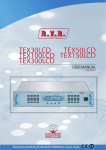
IBJECT12K10A & IBJECT12K10B User Manual Manufactured by Italy File Name: IBJECT12K10A_IBJECT12K10B_ING_1.0.indb Version: 1.0 Date: 06/02/2009 Revision History Date Version 06/02/2009 1.0 Reason First Edition Editor J. H. Berti IBJECT12K10A & IBJECT12K10B - User Manual Version 1.0 © Copyright 2009 R.V.R. Elettronica SpA Via del Fonditore 2/2c - 40138 - Bologna (Italia) Telephone: +39 051 6010506 Fax: +39 051 6011104 Email: [email protected] Web: www.rvr.it All rights reserved Printed and bound in Italy. No part of this manual may be reproduced, memorized or transmitted in any form or by any means, electronic or mechanic, including photocopying, recording or by any information storage and retrieval system, without written permission of the copyright owner. HD Radio™ Technology Manufactured Under License From iBiquity Digital Corp. U.S. and Foreign Patents. The HD Radio™ and HD Radio logo are proprietary trademarks of iBiquity Digital Corp. IBJECT12K10A & IBJECT12K10B Table of Contents 1. 2. 3. 3.1 3.2 4. 4.1 5. 5.1 6. 6.1 7. Preliminary Instructions Warranty First Aid Treatment of electrical shocks Treatment of electrical Burns Unpacking General Description Installation and configuration procedure Preparation External Description Front Panel Technical Specifications User Manual Rev. 1.0 - 06/02/09 1 1 2 2 2 3 3 4 4 7 6 7 IBJECT12K10A & IBJECT12K10B This page was intentionally left blank ii Rev. 1.0 - 06/02/09 User Manual IBJECT12K10A & IBJECT12K10B IMPORTANT The symbol of lightning inside a triangle placed on the product, evidences the operations for which is necessary gave it full attention to avoid risk of electric shocks. The symbol of exclamation mark inside a triangle placed on the product, informs the user about the presence of instructions inside the manual that accompanies the equipment, important for the efficacy and the maintenance (repairs). 1. Preliminary Instructions WIRING: This device has a connection to ground on the power cord and on the chassis. Check that they are correctly connected. • General foreword Operate with this device in a residential ambient can cause radio disturbs; in this case, it can be demanded to the user to take adequate measures. The equipment in object is to considering for uses, installation and maintenance from “trained” or “qualified” staff, they conscious of the risks connected to operate on electronic and electrical circuits electrical. The “trained” definition means staff with technical knowledge about the use of the equipment and with responsibility regarding the own safety and the other not qualified staff safety place under his directed surveillance in case of works on the equipment. The “qualified” definition means staff with instruction and experience about the use of the equipment and with responsibility regarding the own safety and the other not qualified staff safety place under his directed surveillance in case of works on the equipment. Specifications and informations contained in this manual are furnished for information only, and are subject to change at any time without notice, and should not be construed as a commitment by R.V.R. Elettronica SpA. The R.V.R. Elettronica SpA assumes no responsability or liability for any errors or inaccuracies that may appear in this manual, including the products and software described in it;and it reserves the right to modify the design and/or the technical specifications of the product and this manual without notice. • Warning regarding the use designated and the use limitations of the product. WARNING: The machine can be equipped with an ON/OFF switch which could not remove completely voltages inside the machine. It is necessary to have disconnected the feeding cord, or to have switched off the control panel, before to execute technical operations, making sure himself that the safety connection to ground is connected. The technical interventions that expect the equipment inspection with circuits under voltage must be carry out from trained and qualified staff in presence of a second trained person that it is ready to intervene removing voltage in case of need. R.V.R. Elettronica SpA doesn’t assume responsibility for injury or damage resulting from improper procedures or practices by untrained/unqualified personnel in the handling of this unit. This product is an transmitter radio indicated for the audio broadcasting service in frequency modulation. It uses working frequencies that are not harmonized in the states of designated user. The user of this product must obtain from the Authority for spectrum management in the state of designated user the appropriate authorization to use the radio spectrum, before putting in exercise this equipment. The working frequency, the transmitter power, let alone other specifications of the transmission system are subject to limitation and definited in the authorization obtained. 2. Warranty R.V.R. Electronics S.P.A. guarantees absence of manufacturing defect and the good operation for the products, within the provided terms and conditions. WARNING: The equipment is not water resistant and an infiltration could seriously compromise its correct operation. In order to prevent fires or electric shocks, do not expose the equipment to rain, infiltrations or humidity. Please read the terms carefully, because the purchase of the product or acceptance of order confirmation, constitutes acceptance of the terms and conditions. Please observe all local codes and fire protection standards during installation and use of this unit. Warranty will be void in cases of opened products, physical damage, misuse, modification, repair by unauthorised persons, carelessness and using the product for other purpose than its intended use. WARNING: The equipment has to its inside exposed parts to risk of electric shock, always disconnect power before opening covers or removing any part of this unit. Fissures and holes are supplied for the ventilation in order to assure a reliable efficacy of the product that for protect itself from excessive heating, these fissures do not have to be obstructed or to be covered. The fissures doesn’t be obstructed in no case. The product must not be incorporated in a rack, unless it is supplied with a suitable ventilation or that the manufacturer’s instructions are been followed. WIRING: This equipment can irradiate radio frequency energyand if it’s not installed following the instructions contained in the manual and local regulations it could generate interferences in radio communications. User Manual For the last legal terms and conditions, please visit our web site (WWW.RVR.IT) wich may also be changed, removed or updated for any reason without prior notice. In case of defect, proceed like described in the following: 1 Contact the dealer or distributor where you purchased the unit. Describe the problem and, so that a possible easy solution can be detected. Dealers and Distributors are supplied with all the information about problems that may occur and usually they can repair the unit quicker than what the manufacturer could do. Very often installing errors are discovered by dealers. 2 If your dealer cannot help you, contact R.V.R. Elettronica and explain the problem. If it is decided to return the unit to the factory, R.V.R. Elettronica will mail you a regular authorization with all the necessary instructions to send back the goods; 3 When you receive the authorization, you can return the unit. Pack it carefully for the shipment, preferably using the original packing and seal the package perfectly. The customer always assumes the risks of loss (i.e., Rev. 1.0 - 06/02/09 /8 IBJECT12K10A & IBJECT12K10B R.V.R. is never responsible for damage or loss), until the package reaches R.V.R. premises. For this reason, we suggest you to insure the goods for the whole value. Shipment must be effected C.I.F. (PREPAID) to the address specified by R.V.R.’s service manager on the authorization DO NOT RETURN UNITS WITHOUT OUR AUTHORIZATION AS THEY WILL BE REFUSED 4 Be sure to enclose a written technical report where mention all the problems found and a copy of your original invoice establishing the starting date of the warranty. Figure 5 Replacement and warranty parts may be ordered from the following address. Be sure to include the equipment model and serial number as well as part description and part number. R.V.R. Elettronica SpA Via del Fonditore, 2/2c 40138 BOLOGNA ITALY Tel. +39 051 6010506 3. First Aid 3.1.2 • In case of only one rescuer, 15 compressions alternated to two breaths. • If there are two rescuers, the rythm shall be of one brath each 5 compressions. • Do not interrupt the rythm of compressions when the second person is giving breath. • Call for medical assistance as soon as possible. If victim is responsive • Keep them warm. The personnel employed in the installation, use and maintenance of the device, shall be familiar with theory and practice of first aid. • Keep them as quiet as possible. • Loosen their clothing (a reclining position is recommended). 3.1 • Call for medical help as soon as possible. 3.1.1 Treatment of electrical shocks If the victim is not responsive Follow the A-B-C’s of basic life support. • Place victim flat on his backon a hard surface. • Open airway: lift up neck, push forehead back 3.2 3.2.1 (Figure 1). Treatment of electrical Burns Extensive burned and broken skin • Cover area with clean sheet or cloth. • Do not break blisters, remove tissue, remove adhered particles of clothing, or apply any salve or ointment. • Treat victim for shock as required. • Arrange transportation to a hospital as quickly as possible. • If arms or legs are affected keep them elevated. If medical help will not be available within an hour and the victim is conscious and not vomiting, give him a weak solution of salt and soda: 1 level teaspoonful of salt and 1/2 level teaspoonful of baking soda to each quart of water (neither hot or cold). Figure 1 • clear out mouth if necessary and observe for breathing • if not breathing, begin artificial breathing (Figure 2): tilt head, pinch nostrils, make airtight seal, four quick full breaths. Remember mouth to mouth resuscitation must be commenced as soon as possible. Allow victim to sip slowly about 4 ounces (half a glass) over a period of 15 minutes. Discontinue fluid if vomiting occurs. DO NOT give alcohol. 3.2.2 Less severe burns Figure 2 • Check carotid pulse (Figure 3); if pulse is absent, begin artificial circulation (Figure 4) depressing sternum (Figure 5). Figure 3 /8 • Apply cool (not ice cold) compresses using the cleansed available cloth article. • Do not break blisters, remove tissue, remove adhered particles of clothing, or apply salve or ointment. • Apply clean dry dressing if necessary. • Treat victim for shock as required. • Arrange transportation to a hospital as quickly as possible. • If arms or legs are affected keep them elevated. Figure 4 Rev. 1.0 - 06/02/09 User Manual IBJECT12K10A & IBJECT12K10B 4. Unpacking The package contains: 1 IBJECT12K10A o IBJECT12K10B 1 User Manual The following accessories are also available from Your R.V.R. Dealer: • Accessories, spare parts and cables 4.1 General Description The IBJECT12K10A and IBJECT12K10B, henceforth to commonly named IBJECT12K10, manufactured by R.V.R. Elettronica SpA, are injectors able to mix a digital signal (maximum power 2.5 kW) to an existing FM analog signal (maximum power 12.5 kW), using the same system of antenna and power cord. It meets all HD RADIO™ standards and, according to RVR’s philosophy, it has been made with rugged designs. The injector has been designed to perform an easy installation. User Manual Rev. 1.0 - 06/02/09 /8 IBJECT12K10A & IBJECT12K10B 5. Installation and configuration procedure This section provides a step-by-step description of equipment installation and configuration procedure. Follow these procedures closely upon first power-on and each time any change is made to general configuration, such as when a new transmission station is added or the injector is replaced. Once the desired configuration has been set up, no more settings are required for normal operation. The topics covered in this section are discussed at greater length in the next sections, with detailed descriptions of all hardware features and capabilities. Please see the relevant sections for additional details. IMPORTANT: When configuring and testing the injector in which the equipment is integrated, be sure to have the Final Test Table supplied with the equipment ready at hand throughout the whole procedure; the Final Test Table lists all operating parameters as set and tested at the factory. 5.1 Preparation 5.1.1 Preliminary checks Unpack the IBJECT12K10 and immediately inspect it for transport damage. Ensure that all connectors are in perfect condition. Provide for the following (applicable to operating tests and putting into service): √ Connection cable kit including: • Cables, with connector 1+5/8“ (not included), between IBJECT12K10 and sources of FM analog transmission, and between IBJECT12K10 and output in antenna. • Cables, with connector 7/16 DIN (not included), between IBJECT12K10A and sources of IBOC digital transmission, and between IBJECT12K10A and output in dummy load. If you are using the IBJECT12K10B version, use cable with connector 7/8 EIA. The IBJECT12K10 must be installed on a rack that includes an anti-strap device to prevent the possibility of accidental disconnection of feeding conductors. /8 Warning: Disconnect mains power supply before beginning these procedure. Rev. 1.0 - 06/02/09 User Manual IBJECT12K10A & IBJECT12K10B An example of connection is represented in the figure below: HD RADIO SIGNAL GENERATOR HD RADIO DRIVER & AMPLIFIER TDX-IBOC001 E2X LINK EXPORTER DJ50 DJ1000 ANALOG - DIGITAL COMBINER / INJECTOR ANALOGIC FM TRANSMITTING SOURCE IBJECT12K10 RVR’s transmitting Equipment used: ● PTX-DDSFamily ● PTX-LCDFamily ● TEX-LCDFamily DUMMY LOAD Figure 5.1: High level mixed signal NOTE with the addition in a system of IBJECT12K10 the analogic output is downgraded of 10% and the digital output of 90%. For example, an analog 10kW will provide in a antenna 9kW and a digital 1000W will supply 100W. User Manual Rev. 1.0 - 06/02/09 /8 IBJECT12K10A & IBJECT12K10B 6. External Description This section describes the components present on equipment. 6.1 Front Panel Figure 6.1 [1] ANALOG IN [2] REJECTED OUT [3] DIGITAL IN [4] ANTENNA OUT /8 RF input connector for analog FM source, 1+5/8” type. RF ouput connector of rejected power for dummy load, 7/16 DIN type (IBJECT12K10A version) or 7/8 EIA type (IBJECT12K10B version). RF input connector for digital IBOC source, 7/16 DIN type (IBJECT12K10A version) or 7/8 EIA type (IBJECT12K10B version). RF output connector for antenna, 1+5/8” type. Rev. 1.0 - 06/02/09 User Manual IBJECT12K10A & IBJECT12K10B 7. Technical Specifications Parameters Conditions IBJECT12K10A IBJECT12K10B U.M. Value Value Notes MHz W kg °C dB dB dB 87.5 ÷ 108 12.5 kW Analog and 2.5 kW Digital About 7 kg -50 to + 70 At least 38 10 At least 26 87.5 ÷ 108 12.5 kW Analog and 2.5 kW Digital About 7 kg -50 to + 70 At least 38 10 At least 26 Whithout condensing 1+5/8" EIA 50 7/16 DIN 50 1+5/8" EIA 50 7/8 EIA 50 1+5/8" EIA 50 7/16 DIN 50 1+5/8" EIA 50 7/8 EIA 50 GENERALS Frequency range Rated output power Weight Ambient working temperature Isolation Coupling Return Loss INPUTS Analog Intput Digital Input Connector Impedance Connector Impedance OUTPUTS Antenna Output Rejected output User Manual Connector Impedance Connector Impedance Ohm Ohm Ohm Ohm Rev. 1.0 - 06/02/09 /8 IBJECT12K10A & IBJECT12K10B This page was intentionally left blank /8 Rev. 1.0 - 06/02/09 User Manual