1
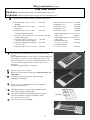
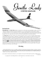
Instructions
Introduction. The Gentle Lady sailplane was designed to be a gentle trainer for the beginning R/C modeler, yet to possess
competition capability in the hands of the experienced glider pilot. As a very efficient machine, she reacts quickly to rising air
( called lift, or thermals). To stay in the thermal, she can circle very tightly without falling off. The model has good penetration into
the wind and can really “cruise” when desired. Before starting to build, read through these instructions and familiarize yourself with
the plans. If a 6-1/2 ft. wing will not fit into your car, you will want to build the wing version with removable tips.
The Gentle Lady can be flown a number of ways: hand tow, high-start, slope soar, or power. The simplest method is hand tow,
which resembles towing a kite into the air. High-start is a combination of elastic cord and tow line. When stretched, the high-start
will gently tow the model up to an altitude of several hundred feet from which a flight of three minutes or more in dead air ( no
Thermals) can be obtained. A variation of the high-start is the more expensive powered winch, popular with glider clubs. If you live
near unobstructed hills or ridges, slope soaring is easily possible, so long as you have a suitable landing area. Hand launching the
model off the upwind side of the slope, directly into the wind, will enable you, with practice, to soar back and forth along the slope
in the rising air for as long as the wind remains. Finally, the use of power is an excellent option, and this book and the plan show
typical installations. For the modeler who wishes to power fly the Gentle Lady at all times, nose mounting of engine is recommended. Pod mounting has two advantages: the power pod assembly can be easily removed for flying the model as a pure glider,
and engine oils are less likely to dirty the fuselage.
Warning
A radio-controlled model is not a toy. It is capable of causing serious bodily injury and property damage. It is the buyer’s responsibility to build this kit correctly and to properly install the motor, radio, and all other equipment. The first test flights should be made
only with the assistance of an experienced R/C flyer. The model must always be operated and flown in accordance with the safety
standards of the Academy of Model Aeronautilcs.
Per the Federal Communications Commission, you are required to use only those radio frequencies specified “for Model Aircraft.”
Pt. #2044- 2/97
© Copyright 1981 Carl Goldberg Products, P.O. Box818 Oakwood, Ga. 30566 Phone 678 450 0085
1
Items needed to complete this kit. Necessary Tools and Supplies.
1 Radio Guidance system( 2 channel
Miscellaneous Rubber Bands
minimum required)
2 Rolls covering material
Roll of waxed Paper
Modeling Knife and Single Edge Razor Blade
1 2oz. bottle CA glue
1 CA accelerator
Sandpaper( assorted grits, including Medium(150) and
Fine(220-320)
1 30 minute epoxy
Sanding Block
1 Tub Balsa-tinted CGP Model Magic™.
“T” Pins (at least 50)
1
Box #64 Rubber bands.
Building Board (24”x70”)
1
Servo mounting Tape
Electric Drill
1
1/4 x 8 x 12” CGP Foam Padding
1/16” Drill Bit
CGP Scuff Guard ( To Protect Bottom From
Scratching)
1/8” Drill Bit
Allen Wrench (.050 for #4 socket set screw)
For Removable Tip Option
1
1/8” x 3” x 18” Balsa Sheet
Small Screwdriver (1/8” Blade Tip)
1
Piece 3/32” Dia. x 6” Music Wire
Covering Iron and Heat Gun
Masking Tape
1 3/32” x 6” GCP Nylon Reinforcing Tape
For Engine Power
Pliers
Flexible Straight-Edge
Engine, Propeller, Mounting Screws, Nuts, and
Washers
30-60 Degree x 6” Triangle
For Servo Mounting
CGP #360 Pushrod Connectors
Pencil
Selecting Radio Control
Equipment
Limited Warranty
Carl Goldberg Models takes pride in the care and attention given
to the manufacture of components for its model airplane kits.
The company warrants replacement of any materials found to be
defective for their intended use, prior to their use in construction of the aircraft, provided the buyers requests such replacement within a one year period from the date of purchase and
provided the defective part is returned, if so requested by the
company.
No other warranty, expressed or implied, is made by the
company with respect to this kit. The buyer hereby assumes full
responsibility for the risk and all liability for personal or property damage or injury arising out of the buyer’s use of the components of this kit.
Radio sets are battery powered with either dry cells or the more
reliable, rechargeable nickel-cadmium (ni-cad) batteries.
Although ni-cad powered units are more expensive, the cost of
routinely replacing worn out batteries may be much higher in the
long run. Many of the radio systems now available feature
“servo reversing” switches which allow you to reverse the
response of the servo. This simplifies radio installation and is
worth considering. Exponential or dual rates are popular features
which , if used properly, can help smooth out the flight of a sensitive model. Your local hobby dealer should be able to help you
select the proper radio for your needs and skill level. And be
sure to get a system designed for aircraft, as only certain frequencies are available for model aircraft.
2
Using This Instruction Manual
Introduction
Before you start gluing and sanding, take some time to look
through this entire instruction booklet. It is designed to guide you
through the construction process step by step, so build in the order
given in this book. Radio selection and installation, covering, and
balancing and flying the model are all covered. Also spend time
becoming familiar with the plans.
Like a full-size airplane, the Gentle Lady is built from basic
structures (stablizer, fin, wing, etc.), which are then assembled
into the complete airplane.
Special procedures or comments will usually be explained
before a step, so you will be prepared. If a step begins with a
statement like “Note,” “Warning,” or “Important,” it is a good
idea to read through the step before doing it.
A check-off box appears at the beginning of each step. Check
these boxes as you build, so you can tell at a glance what steps
you have completed. Some steps require you to repeat them, as
in the case of the left and right wing panel.
Some of the instructions deal with general procedures. Boxes
are not needed for these sections.
How to read the plan
The plan shows the Fuselage ( Body), the Wing, and the Tail
Parts. Everything on the plan is drawn to full-size and shape
and shows how the finished parts fit together.
The plan is drawn to show the model completely assembled,
but as a result, the areas inside or underneath are covered up,
making it hard to understand how these parts fit together.
Therefore, for clarity, some parts are drawn with hidden lines ,
others with breakway views, and some are entirely removed
from the structure and shown separately.
For example, on the fuselage, the left side of the completed
model has been removed to show the details inside. Sometimes
a surface is broken away to reveal the detail behind or underneath. Dashed lines indicate details that are hidden behind or
under another part of the surface.
The model is made from four varieties of wood: balsa, bass,
birch, and various plywoods. Each kind of wood has its own
characteristic end grain pattern (as viewed from the end) which
has been drawn on the plan.You can easily use these end grain
patterns to identify what kind of wood is shown for a part, if
you are in doubt.
How to use the plan
The plan is used in several ways. The wings, stabilizer, and fin
are assembled directly over the plan. Each wood part is
matched over its corresponding location printed on the plan
and pinned in place. To prevent ruining your plan from gluing
your wings, etc. to it, cover the area you are working on with
waxed paper or plastic kitchen wrap.
The paper the plan is printed on can expand or contract slightly with changes in temperature or humidity. Because of this, a
preformed part such as the notched wing trailing edge may not
exactly match the plan. This is no problem, as slight deviations
in the outline or size will not noticeably affect flight performance.
Because the fuselage plugs together and is self-aligning, it is
not built directly over the plan. However, make sure the stabilizer and fin are mounted square and true to the fuselage. As
you assemble the fuselage, you will find the plan helpful in
identifying parts and how things fit together.
3
The plan also shows the installation of a typical radio, battery and
all remaining equipment and hardware needed to complete the
model. By referring to the examples shown, you should be able to
install your own radio, etc., even if it is not the same as what is
shown on the plan.
Identifying Parts
Parts for the wing are bundled together; likewise, parts for the tail
assembly are also grouped. Die-cut plywood and balsa sheets of
common sizes are bundled together, so they are less likely to be
damaged during shipping and handling.
The various screws, hinges, and fittings are packaged in plastic
bags.
Preparing For Assembly
Place a flat, warp-free pinning board on your work bench. Any
material that accepts pins, such as insulation board, soft plywood,
or dry-wall (sheet rock) will work. Important: any warps or
bends in the pinning board will result in wings or tail surfaces
that are also warped or bent, making your model more difficult
to fly. Make sure that the pinning board is flat by laying a straight
edge across it. You may be able to correct a warped board by shimming its low areas.
Position the area of the plan (such as the stabilizer) on which you
are going to build over the pinning board and tape it in place so the
plan lies flat and wrinkle free.
Place a sheet of waxed paper or plastic kitchen wrap over the work
area to prevent CA from sticking to your plan and ruining it.
Construction Tips
If you have never assembled a built-up model before, the following tips will prove helpful.
IMPORTANT: ALWAYS READ A FEW STEPS AHEAD. This
will alert you to coming instructions and will help you plan accordingly.
You may find it convenient to empty all of the small parts from the
hardware bags into a common container, such as a margarine tub.
This will help you find items quickly.
When drilling any 1/16” holes in balsa, you may find it easier to
twist the drill between your thumb and index finger. This procedure
allows more control in positioning the drill on the center mark.
Punch out only the die-cut (D/C) parts you need as you proceed.
This will help you keep track of parts, especially the small ones.
After completing each section of the aircraft, you may want to go
back and reglue the joints, just in case some area has been missed.
Be careful not to use too little glue, which will leave the model
weak or too much glue, which can make the model heavy.
Properly glued joints are important to the overall strength of the
model. CA is recommended for most parts of the assembly,
although epoxy may be used when more time is needed for careful
placement.
Wood Parts
About The Wood In The Kit
Be careful when removing parts (such as fuselage sides) from
the die-cut sheets. Long parts are fragile until glued into a structural unit. If necessary, use a razor knife or razor saw to assist in
the removal of parts from the sheet. Sometimes a little trimming
and sanding can improve parts, where desired. Save scrap until
the model is completed, in case a part is missing or damaged.
Also, scrap is used in some building steps. Solid lines indicate
die-cut parts; dashed lines indicate cuts to be made as described.
Some easily recognized pieces, such as nose block, are not
shown.
Parts Identification: Heavy lines indicate die-cut parts.
Dashed lines indicate cuts to be made as described in the instructions.
4
We strive to supply good quality materials in your kit. Wood
parts are inspected with regard to the function they will serve. If
an imperfection is spotted in a scrap corner of a die-cut sheet
and doesn’t affect actual parts, the sheet is considered acceptable. Also, internal stresses in wood are relieved as it is cut into
parts. These relieved stresses may cause some parts to bow.
Bows in wood parts (such as leading edges) readily straighten
out as they are glued into a structural unit.
Horizontal and Vertical Stabilizer Construction (6 Steps)
Important: This booklet has recently been revised. Therefore, some of the steps in the booklet may not match what is shown
on the plan. Whenever you find such a divergence, follow the instructions in this booklet.
1. Collect all of the items you will need to construct the HORIZONTAL STABILIZER. They include:
(1) D/C Sheet 6006 (3/16” Balsa)
Pt.#3455 (5) TAIL L.E. & T.E. (3/16” X1/4” X21”)
Includes: (1) STAB CENTER
(3) TAIL TRUSSES (5/64” X3/16” X24”)
(2) STAB TIPS
(1) RUDDER T.E. (3/16” X9/16” X8”)
(1) DORSAL
(1) ELEVATOR GUSSETS
(1) FIN BOTTOM
PT. #4697
PT. #4698
PT.#4701
PT#4696
Select strongest pieces for stab L.E. and T.E.
2.
Lie the horizontal stabilizer portion of the plan over the
building board and place the waxed paper over the plan.
The main members of the tail assembly are 3/16” x 1/4”
balsa strips. Check to see which strips are the strongest,
and use these for the stabilizer. Lighter ones can be used
in the fin and rudder.
Pin in position and glue at center joint.
Using die-cut stab tips, the center platform and 3/16” x 1/4”
balsa, assemble stab outline.
In cutting the diagonal trusses for the tail, trim them to fit
well. If a bit oversize, don’t force them in place. The
pieces should fit before gluing. It’s better to have them not
meet at the points than to force them in.
Let all parts dry thoroughly.
Fit trusses carefully. Don’t force in place.
Gussets
Assemble fin and rudder in same manner.
3.
Note: Trailing edge of rudder is tapered.-use 1/16” x12” wire
for shim as shown.
Add gussets and let dry throughly.
4.
Temporarily tack-cement elevator to stab, and rudder
to fin (to be removed later). Flat sand parts for uniform
smooth surfaces. Then sand edges, rounding corners and
blending surfaces. Important: Do Not sand the lower
2” of fin L.E. at this time.
Carefully separate elevator and rudder from main units.
5.
Lie the widest side of both 3/4” x 3/4” tri-strips down. Align
strips using a straight edge and separate them by about 3”.
Pin in position.
Position elevator so that its trailing edge rests on top of
tri-strips. Pin elevator in place.
Using a square cornered block, sand front surface of
elevator to match with view on plan.
6.
Bevelling Elevator
Pin down 3/4” wide side of one tri-strip. Position rudder so
it rests against angled side of tri-strip. Pin in place.
Sand front surface of rudder to match with view on plan.
Beveling Rudder
5
Wing Construction (13 steps)
Wing Terms Defined
Dihedral-The upward bend of the wings, which usually starts at wing center.
Polyhedral- Additional dihedral at the wing tips, often used with glider wings.
1.
Collect the items needed to construct the WING. They include:
(2) D/C Sheet 6001 (5/64” x3” x24”)
Wing Rib
(2) D/C Sheet 6002 (5/64” x3” x24”)
Wing Ribs
(1) D/C Sheet 6005 (1/16” x3” x24”)
PT.# 3450
PT# 3451
PT# 3454
Includes: Double Spar Spacers
(1) D/C Sheet 6008 (1/16”Ply x 2-7/16” x 15-3/16”) PT# 3457
Includes:Wing Joiners
(1) D/C Sheet 6009 (1/8” Ply x2” x17”)
PT# 3458
Includes: Wing Joiners and Braces
(1) Wing, Fuse Top & Bottom Sheeting
PT# 4686
(1/16” x3” x24”)
(2) Wing Sheeting (1/16” x 2-1/2” x24”)
PT#4687
2.
3
(2) Tri-strips (5/16” x5/16” x4”)
(2) Inboard T.E. (L)
(2) Outboard T.E. (S)
(2) Inboard L.E. (L)
(2) Outboard L.E. (S)
(2) Inboard Main Spar (1/4” x7/16” x20-3/4”)
(Bass wood)
PT#4692
(2) Inboard Rear Spar (1/8” x1/4” x20-3/4”
(Bass wood)
PT# 4693
(2) Outboard Main Spar
(1/4” x7/16” x17-5/8”)
PT# 4694
(2) Outboard Rear Spar
1/8” x1/4” x 17-5/8”)
PT# 4695
Place the plan on a building board or other flat surface. Working
over the
RIGHT INBOARD PANEL section of plan, pin inboard leading and
trailing edges (L.E. & T.E.) in place. Align notches in T.E. with
those shown on plan. Cut two pieces of bottom sheeting from 1/16”
x 2-1/2” x24” balsa. Then fit and trim one piece from 1/16” x3”
x24” balsa.
Assemble sheeting and glue to L.E. and T.E.
Glue ribs 6 and 7 to L. E. and T. E.
Position 1/8” ply spar brace in front slots, but DO NOT GLUE AT
THIS TIME.
Continuing to work on a flat surface, position and glue
remaining ribs 2 through 8.
Position 1/16” die-cut balsa spacers in rib slots, and glue to
bottom sheeting per sketch.
4.
Sand dihedral angle in one end of bass wood main and rear
spars, following angle indicated on plan.
Insert spars through ribs, with dihedral angle at wing center
joint. Use a flat block to sand spar ends flush with the
L.E. and T.E. at sheeted end.
Glue spars to ribs 5,6,7 and 8 Only.
6
PT# 4876
PT# 4688
PT# 4689
PT#4690
PT#4691
1/16” spacers
Stuff double thickness of wing rib scrap into rib slots as
shown in sketch to center spars in their respective slots.
Glue spar bottoms to spacers.
Glue spar brace firmly to spar. Let dry thoroughly.
5.
Using a square-cornered sanding block, lightly sand L.E.
and T.E. to match with spar angles.
6.
Pin RIGHT OUTBOARD L.E. and T.E. in place over
plan.
Position and glue ribs 10 through 18. Add gusset at corner
of rib 18 and T.E.
NOTE:IF YOU ARE MAKING THE WING WITH THE
REMOVABLE TIP OPTION, OMIT THE NEXT 3 BOXES AND
PROCEED DIRECTLY TO STEP 7.
Sand one end of spars for proper polyhedral angle shown
on plan.
Slide spars in place (angled ends at rib 9 position), but
do not yet glue.
Lightly sand L.E. and T.E. to conform to spar polyhedral
angles. Proceed directly to Step 8.
NOTE: Some people have wondered why we show an optional 3-piece
wing. The reason is that, in a 2-piece wing, the structural requirements
at the center are very high. This leads to a more difficult structure, and
a heavier one. Having removable outboard panels is much simpler and
lighter.
IMPORTANT
THIS STEP IS FOR THE REMOVABLE TIP OPTION ONLY!
7.
Cut four new #9 ribs from 1/8” hard balsa, using rib
pattern at upper right corner of plan labeled
“REMOVABLE TIP
OPTION.” Do not use die-cut rib #9.
Use SANDING ANGLE TEMPLATE (cut or copy
from
right corner of plan) and 1/8” ply scrap to establish
proper sanding block angle, as shown in sketch.
Slide outboard spars in place, but do not glue yet.
Gently sand polyhedral ends of spars, L.E.’s and T.E.’s
for uniform vertical surfaces.
7
Scrap material for spacing-Do not glue
Position outboard and inboard panels together at polyhedral
joint. Raise wing tip end of outboard panel 4” off work
surface. With outboard spars touching inboard spars, glue
outboard spars to ribs.
Position 3/32” x3” wire on back of spars as shown, and
mark wire location on spars. Carefully groove spars for wire
and brass tube respectively, as shown in TIP OPTION
detail on plan.
Tack-cement wire to outboard spar, and brass tube to
inboard spar. Plug wing panels together, re-check wing
tip height (4”), and observe that wing structures butt evenly
at polyhedral joint. If corrections are necessary, rework
grooves slightly, then reglue metal parts in place.
Position the #9 ribs on spars and plug wing panels together.
Butt these ribs at the polyhedral joint, tilting them slightly
towards the inboard panel, so that they match the spar
angles. Carefully glue ribs to their respective wing panels.
BE CAREFUL TO AVOID gluing the panels together.
Remove outboard panel. Using 3/4” wide nylon fabric and
CA or Epoxy, securely bond wire and brass tube
in place. Securely glue #9 ribs in place.
Add gussets.
NOTE: Later on, after wing parts have been covered, the
removable tip panels are fastened to inboard wing sections using
vinyl electrical tape. This tape holds firmly, yet can be removed without damaging covering material.
PROCEED DIRECTLY TO STEP 9.
NOTE: Some people have tried to get a slightly better glide with the
Gentle Lady by flattening the polyhedral of the wing somewhat.
Unfortunately, this degrades the turning ability of the ship and it is
no longer able to respond quickly. We recommend keeping the polyhedral measurements as indicated.
8.
9.
10.
Position rib #8 on inboard spars, and slide it over next to
rib #8.
Position outboard and inboard panels together at polyhedral
joint. Raise wing tip 4” off work surface. Join inboard to
outboard spars using 1/16” ply joiners. Clamp until dry.
Glue L.E. and T.E.’s together.
Glue rib #9 at polyhedral joint and add gussets.
Glue outboard spars to ribs.
Repeat steps 2 through 8 for left inboard and outboard
panels
Trim off excess spar material extending beyond ribs #18.
Glue balsa tri-strips in place on wing tips.
Carve and sand, following top contour of rib (see plan).
8
4”
11.
DO NOT USE GLUE YET. Temporarily join wing
panels, using 1/8” ply joiners. Observe and correct fit and
placement of parts for proper dihedral angle. (Each tip
should be about 6-3/8” above the work surface.) Separate
panels and remove joiners.
Now, permanently glue joiners into one side of wing.
Working carefully, apply a slow setting glue, such as
Slow ZAP, to joiners and slide them into position. Clamp
until dry.
Apply glue to joiners, ect., and join both wing halves.
Again check for correct dihedral-each wing tip should be
about 6-3/8” above the table. Clamp joiners and let wing
assembly dry thoroughly.
Glue ribs #2, 3 and 4 to spars and joiners. Turn wing
upside down and glue ribs #3 through #18 to spar
bottoms. Examine entire wing, top and bottom, for any
joints which still need to be glued.
From two 3/16”x1/4” strips
(not furnished)
cut 10-3/4” pieces
Glue two of rib 1 together to make double thickness rib.
Glue doubled rib 1 at dihedral joint.
NOTE: If you’re going to fly a lot in windy weather or use a
powerful winch, you may want to strengthen the wing as follows.
Before adding the sheeting in step 12, notch each rib from the top
down to the spar, on ribs #1,2,2,3, 4 and 5. Glue to the top of the
spar a strip of hard balsa 3/16”x1/4”x10-3/4” (not furnished),and
sand it lightly to match the rib curvature. When the sheeting is
glued in place, glue it also to the 3/16” strip.
12.
Balsa strip
Cut L.E. sheeting from 2-1/2” balsa. Glue sheeting
securely to L.E., ribs and center joint.
From 2-1/2” and 3” wide balsa, make remaining sheeting
pieces and glue in place.
13.
Cut and sand a recess in T.E. at dihedral joint for
rubber bands.
Flat sand entire wing smooth.
9
Typical Rib
Notching
FUSELAGE CONSTRUCTION (18 Steps)
1.
Collect all of the items you will need to construct the FUSELAGE. They include:
(1) D/C Sheet 6008 Front Bottom/Triplers
( 1/16”x2-7/16”x15-3/16” ply)
(1) D/C Sheet 6009 (1/8”plyx2”x17”)
Doublers/Servo rails
(1) D/C Sheet 6005 (1/16”x3”X24”)
Main fuse top/Middle fuse bottom
(2) D/C Sheet 6004 (5/64”x2-7/8”x18”)
Fuselage doubler
PT.#3457
PT#3458
PT#3454
PT#3453
(2) D/C 6003 (5/64”x2-7/8”x36”)
Fuselage Side 2 front and 2 rear
(1) D/C Sheet 6007 (1/8”x2-1/4”x14”)
Formers/Hatch
(1) Balsa sheet/Fuse top (1/16”x3”x24”)
(1) Firewall (1/8”x1-7/16”x1-9/16”ply)
(1) Nose Block
(4) Fuse longeron (1/8”SQ. x36”)
(2) Dowel (3/16”x3/4”)
PT#3452
PT#3456
PT#4686
PT#4685
PT#4704
PT#4705
PT#1746
Fuselage side construction
2.
3.
Locate the front and rear half of each fuselage side. They will need to be glued together at the finger joint
to form a complete side.
Trial fit the front and rear half of the fuselag sides.
Lay out a piece of wax paper over the plans long enough to cover the fuselage sideview.
Use the plans as a guide to make sure the fuselage sides are straight. When everything is aligned properly glue with
thin CA glue. You don’t have to take the sides apart, the thin CA will “wick” right into the joint.
After the glue has cured, use a sanding block and make sure the joint is smooth.
10
Fuselage
equal spacing
flush
Match up notches
Flush
4.
5.
set carefully in correct position and pressed down fimly,
the adhesive is squeezed into a very thin layer and
sets up almost instantaneously. (Epoxy allows more
time for application and adjustment.)
Glue rear pieces of fuselage (fuse) sides.
Temporarily position doublers and check for fit and
correct placement (flush along top edge).
Glue doublers to fuse sides using CA or epoxy.
Apply CA smoothly in a series of ribbons or
stripes to the doubler. Then, when the doubler is
Lie fuse sides over side view on plan and mark
locations of formers 2 and 3.
Refer to plan for locations, then glue 1/16” ply
tongue and balsa brace to hatch.
Glue balsa hole doubler to fuse top.
Glue the 1/16” ply triplers to formers 2 and 3. Then
glue the 1/8” ply doublers to the formers as shown.
Carefully drill 3/16” dowel holes through formers using
die cut holes in doublers as guides. When drilling, lay
formers on scrap wood to prevent break out.
11
6.
Refer to plan for correct location, then cut and glue 1/8”
square longerons to sides. Top longeron starts at former 3
and bottom longeron starts at fuse front. Both longerons
stop at notches in rear doubler.
Glue formers 2 and 3 to right side. Refer to plan to
see which way ply doublers face when properly installed.
Important: Make sure formers stand straight (not tilted) until dry.
Glue left fuse side to formers 2 and 3 and let dry
throughly. Make sure formers 2 and 3 are glued firmly to
fuse sides. Re-glue the joints for additional strength.
7.
From 1/8” die-cut sheet scrap, cut a spacer 1/2” square.
Position fuse assembly over top view outline on plan.
Pull fuse nose together, gluing former 1 in place. Use tape
to hold joint.
Pull tail end together with spacer tack-cemented between
(to be removed later). Spacer should be centered between
fuse top and bottom. Hold with tape.
8.
Position and glue hatch rests so that tops of spacing lugs
are flush with fuse top, and rear lugs butt against former 2.
spacer
When dry, trim spacing lugs off hatch rests.
9.
Glue 3/16” dowels securely in formers 2 and 3.
Glue front fuse top in place.
12
Glue main fuse top, and top rear doubler/stab platform in
place, and let fuse dry thoroughly. Note: Stab platform
fits between the fuse sides.
10.
11.
12.
Remove fuse from work surface, and glue 1/16” ply
bottom and main balsa bottom in place. If necessary,
spread sides in the hatch area to match the width of the
1/16” ply bottom.
From plan, locate the correct position for 1/8” ply tow hook
doubler, and glue securely in place inside fuse.
form
plat
uble
doo
From 1/8” square balsa cut two wing rails, and glue to
fuse sides as shown on plan. Note: front end of rails is
tapered.
Temporarily tack-cement hatch in place (it must be
removed later!)
Glue nose block to fuse front (unless, of course, you
intend to mount an engine there! In that case see next
step).
NOSE-MOUNTED ENGINE OPTION
Remove tank and rotate it 90 degrees so you can sidemount engine. Side-mounting helps to keep gunk off
model.
Center engine on 1/8” ply mount. Mark and drill 3/32”
holes for engine mounting screws.
Wing rest rails
Install engine on mount using screws, washers and nuts as
shown on the plan. Press mounted engine in position to
impress nut locations into former 1. Make recesses in
former 1 for nut clearance.
Gently sand fuse front to remove rough spots. Securely
glue engine mount to fuse front. Let dry.
Remove engine for easier sanding of fuse.
13.
ing
r
Rea
b
r/sta
From 1/16”x3”x18” balsa, cut rear top and bottom sheet(grain running across fuse). Glue sheeting in place.
13
This step for
nose mounted engine
installation only.
14.
Remove 1/2” square spacer from tail end of fuse.
Carefully drill or carve 1/4” hole at bottom of tail
opening for pushrod exit.
NOTE: AFTER SANDING in Step 13, harden pushrod exit area
using CA.
15.
Carve nose to shape as shown in top and side views.
Install wing, holding it in position with rubber bands.
Trim hatch rear to match wing dihedral, so hatch will be
held down by wing, yet can be slid back under wing 1/4”.
Flat sand hatch, nose and complete fuse. For easier
covering, keep nose flat surfaced, with minimal rounding of
corners. (Caution: excess sanding or trimming of stab
mounting area can alter the incidence angle which has
been die-cut on the fuse sides. Sand this area as little as
possible).
16.
Rubber band wing in place on fuse. Viewing model from
rear, see if stab sets level with respect to wing.
Sand stab platform area as may be necessary to provide a
good level fit for stab. Do not alter pre-set stab incidence
angle (exactly horizontal in side view).
Center stab on fuse using a tape measure to obtain equal
distance from side to side, and from nose to rear corner of
each stab tip. Pin in place. DO NOT GLUE AT THIS
TIME.
From 1/8” scrap make a stab leading edge fairing and glue
in place on fuse. (DO NOT GLUE TO STAB).
17.
With stab centered on fuse, mark through stab center hole.
Remove stab and cut hole in fuse top to receive fin trailing
edge.
Re-position stab on fuse and hold in place with pins. Insert
fin trailing edge in stab center hole. View model from front
and carefully align fin so it points exactly straight ahead.
Pin in position.
Mark location, then cut hole for fin leading edge in fuse top.
14
*For better understanding, see hatch
photo at bottom of
page 14
Trial fit fin in place. Glue dorsal fin to fin, but not to fuse.
When dry, watch grain and very carefully trim off die-cut
bumps. Finish sanding.
18.
For rudder pushrod, bend 10” threaded rod as
accurately as possibel over plan. Cut off excess,
leaving about 3/16” at right angle.
Cut 1/16”x12” wire into two 6” pieces.
Make 3/16” bend in one end of 1/16” wire “A”. Drill
holes near each end of balsa pushrod, and make a
groove to recess wires part way.
Glue wire “A” and threaded rod to balsa pushrod.
When dry, taper both ends of pushrod, and round
off corners. Bind with strong thread, and re-glue.
Repeat process for elevator pushrod (Note: it is longer).
HATCH OPERATION
The hatch is held in place by the ply tongue at the
front and by the wing at the rear. In order to open
the hatch without removing the wing, the hatch
rear is trimmed to allow it to slide back under the
wing, thus releasing the hatch front from the fuse
(see sketch below). After hatch is covered, a 1/4”
Push-Pull Screw is installed at the front for fingertip manipulation (after installing screw in hatch, file
point off bottom).
15
POWER POD OPTION
Make saddle from 1/16” ply x 2” x9-1/4”, grain going the
2” direction. Make center notches front and back for
centering with wing hold down bands. Position 1/16” ply
on wing with an approximately 1/4” overlap at leading
edge, and tape or band to curve of wing. While in this
position, add platform of 1/8” ply x 1-3/8” x1-3/4” with
1/8” ply or hard base wedge underneath front to provide
approximately 2 degrees upthrust. Center platform
directly over main spar and cement to saddle. Drill four
holes in base of power pod and screw to saddle platform.
After fuel-proofing, finish, etc. Add four pieces of
1/16” by 1/2” foam tape on underside of saddle to protect
top of wing surface.
COVERING
A good covering job should be preceded by careful sanding. Filling nicks and dents with MODEL MAGIC™, then more sanding.
Any irregularities in the wood surface will show on the covering, so a smooth sanding job is a must for appearance. A simple color
scheme, such as one main color plus some trim, is recommended for the novice.
COVERING THE WNG
1. First read the directions which are supplied with every roll of
covering. Cut a piece of covering slightly larger than one inboard
panel and remove backing.
TRUING WING AND SETTING WASHOUT
Truing the wing is an important step, and should not be
rushed or omitted. Also, “washout” (explained below)
improves the wing’s efficiency, and increases the glider’s
stability at slow speeds (prevents tip stalls).
2. Position covering on bottom of wing and, using a covering
iron (set at proper temperature), tack covering across center of
wing. Working outward, firmly tack the covering to all ribs, and
to the perimeter edges of the wing, gently smoothing out the larger wrinkles as you go. Besides sticking the film firmly to the end
of the panel, run some of the film down the vertical side of the
rib.
3. After sealing all edges, glide iron (or use a heat gun) over interior area to tighten the covering. Trim and iron edges.
4. When the bottom of the panel has been completed, repeat the
process on the top side. Follow the same procedure for all wing
panels.
Whenever overlapping one piece of the film on top of another,
make sure you have at least 1/8” of the top firmly stuck to the
one below for the full width of the joint. Otherwise, with little
carelessness in tightening, you can find yourself having developed an opening to be patched. Where two transparent colors
join, use CGM ColorStripe 1/4” wide to cover joint lines.
16
1. Set inboard panel on a flat surface to detect warp. To
counter any warp found, twist panel slightly in direction
opposite to the warp, and hold position while gliding iron
over covering to re-tension structure. Repeat process
until panel is true.
2. Follow same procedure with other inboard panel.
3. Check first panel and correct any change caused by truing
second panel.
4. Block up wing as shown so polyhedral break and outboard
panel leading edge are flat on table. As necessary, twist
wing while gliding iron over covering. Repeat process
untill 1/4” washout is achieved
5. Follow same procedure for other outboard panel.
Covering the Tail
The rudder and elevator can be hinged using the film covering
hinge technique. This combines covering and hinging into one
operation. Conventional hinges may be used if you perfer. In
that case, center beveling is recommended. The instructions
below apply to fin and rudder also.
1.
Make sure stab trailing edge and elevator leading edge
are perfectly straight. Otherwise binding will occur.
Position 1/32” thick cardboard spacer along top of stab
2.
trailing edge and at least 1/16” back from edge (to avoid
the film adhesive.
Apply covering to bottom of stab, up and around
3.
hinge joint, and elevator bottom.
4.
Flop elevator full down, and remove spacer from stab
top.
Apply top covering, and seal hinge and edges.
5.
6.
Complete covering by trimming off excess film, and
adhering covering firmly to all wood structure except
truss and ribs. Check for trueness on a flat surface,
and correct as necessary.
COVERING THE FUSELAGE
A non-transparent film should be used on the fuse to avoid
showing discolored areas where filler materials were used.
1. Cover the fuse areas in the following order: bottom first,
then the sides, and the top last. Do not cover stab
platform.
2.
To minimize abrasion in landing, triple cover the underside from
the nose to about 6” back.
Finally, it’s a very good idea to place your name, address, phone number , AMA number and the word REWARD! permanently on the
inside wall of the servo compartment. Then if your Gentle Lady
should fly away for any reason, you’ll have a chance of getting it
back!
DECAL INSTRUCTIONS
Clean model surfaces thoroughly before applying
decals. Cut decal sheets apart in sections as needed.
Fold decal in half, front to rear. Open at fold and lay
decal out straight, the protective backing will bubble
away from decal at fold location. Using scissors, cut
backing along bubble, removing about 1” wide strip of
backing. Carefully position decal on model and stick in
place. Working from center, rub decal down while
peeling off backing.
FINAL ASSEMBLY
1.
2.
Obtain some 1/16”x1/4” wing seating foam tape and
attach it to the wing rest areas of the fuselage. This
prevents unexpected shifting of the wing.
Mount wing on the fuse using rubber bands (five
#64s are used for flying). Measure carefully from
the fuselage sides out to the polyhedral breaks
(arrows ‘A’) to be sure that the wing is centered.
Then measure from the polyhedral breaks to the
back end of the fuse (arrows ‘B’) to make sure wing
is square with fuse. Mark the wing and fuse with
matching line-up points. The prototype uses white
Color Stripe to indicate clearly when the wing is
lined up.
17
2.
Trial fit stab in place on fuse, marking it for center,
and adjust as necessary to line up with wing. Then
measure from the stab tips to the fuse front (arrows
‘C’) to make sure stab is square with fuse. To provide
a firm, balsa-to-balsa glue joint, strip covering
(minimum 1/8”) to retain firm covering bond to stab
center. Be certain to leave enough covering bond
to stab center. Likewise, if stab area on fuse was
covered, remove covering. Glue stab firmly to fuse
and let dry.
3.
Trial fit fin in place on fuse/stab (arrow “D”). Strip
covering from fin bottom (if covered) and
respective area on fuse/stab. Glue fin firmly in place,
and square with stab. Let dry.
After covering and final assembly, glue 4” long tri-strip
in place as show above. Cover the top of the tri-strip
with film before placement.
Remove the wing, and make hole on left side of fin
for the rudder pushrod exit guide at location shown
on plan. Trim off one side of the exit guide flange,
so guide will fit flush against the fin.
Try the pushrods in working positon inside the
fuse, but without mini-snaps. Make adjustments as
necessary so threaded rods head right for their
control horns. Move pushrods back and forth to
simulate servo action, and remove and adjust
pushrods as necessary for smooth operation. If
required, trim out channel inside fuse, going
forward from exit guide hole, to make it easier to
get threaded rod up to and out exit guide hole.
When operation is satisfactory, glue exit guide in
place.
Re-install pushrods, and add mini-snaps to the
threaded ends of pushrods.
To open mini-snap, insert small screw driver blade,
then twist. Refer to plan for elevator control horn
location. Connect mini-snap to bottom hole in
horn, and hold horn in place on elevator. Move
elevator up and down to observe control horn and
mini-snap clearance through fuse tail exit. Shift
control horn or trim exit as necessary. Mark
location and install control horn on elevator.
Refer to plan for rudder horn location, and install
horn.
Adjust rudder pushrod as necessary, and connect
mini-snap to 2nd closest hole to hinge.
4.
5.
6.
7.
8.
9.
18
RADIO INSTALLATION
Prepare for installation
1.
2.
3.
The pushrods should be in place in the fuselage
and connected to the control horns. The wires at
the front end of the pushrods should have some
excess length, reaching close to former #2.
Read and follow the instructions that come with your
radio.
If your batteries are dry cells, they should be fresh;
if they are rechargeable nicads, they should be
fully charged.
Radio Pre-Check
Assemble and try the radio before installation.
1.
Move the control stick from side to side. Apply
tape (on which you can write) to the particular plug
from the receiver which goes to the servo that
moves. Mark that plug “RUD”.
If your receiver doesn’t have separate plugs coming from
it, but does have places for the servos to plug in, apply a piece of
tape nearby that you can mark “R” opposite the
appropriate plug-in location.
Move the control stick up and down (away from
you, and towards you). Mark the appropriate plug
or plug -in location “ELEV” or “E”.
NOTE: The servo functions are determined by where they
are plugged into the receiver. Be sure to assemble them the
same way each time so that the servos give you the proper
Hold cables down
responses.
2.
with foam
Foam
Wrappings
Receiver
batttery
(Note notches in forward rail)
Charging Jack
Radio Protection
Locate and protect airborne part of radio. Begin by
installing the servo rails.
1.
With pushrods installed, tape the front wires up out
of the way beneath the 1/8” sq. wing rest strips.
Insert the soft rubber grommets into the mounting
2.
holes of your servos.
Measure from the bottom of your servo to the
underside of a grommet. Add 3/16” to this
measurement. The total is the height of the tip of
the servo rail above the fuselage floor.
3.
epoxy.
4.
19
Mark the inside of the fuselage for the height of
rails.
Notch one rail as necessary to clear the cables
where they exit from the servo. This will be the
forward rail.
Glue the forward rail in place with CA or
Place one servo on the rail. Allow 1/16”
clearance from the back of the servo.
Glue the rear rail in place.
5.
With both servos in position, and approximately
1/16” between them, mark through the grommets
for the location of the servo mounting screws.
Remove the servos. With a 1/16” drill bit, drill
through the rails for the screws.
6.
Determine which is the elevator and which is the
rudder servo. Locate the rudder servo on the left,
and the elevator servo on the right, as shown in the
plans.
Fasten gently with #2 x 3/8” sheet metal screws.
Untape the pushrod wires from the fuselage sides
and hook them up to the servos as shown.
Next, protect the battery pack. Remember, you must have
fresh dry cells or fully charged nicads for flying.
Wrap your battery pack in polyethylene foam or
1.
foam rubber to cushion it against shock. If you are
going to use an engine with your model, foam
rubber is preferable because it is much better at
protecting against vibration. Use scotch or
masking tape to hold the ends of the foam in place.
Because the battery pack is the heaviest piece, it
2.
should be mounted as far forward as possible.
Installing the Receiver
Do not cut the antenna wire attached to the
1.
receiver.
Wrap the receiver carefully in foam, as was done
2.
for the battery pack. Then place the receiver
just to the rear of the battery pack.
Lead the antenna back just under the hatch rest.
3.
Drill a small hole in former #2, and lead the
antenna further back, just under the 1/8”
sq. balsa wing rest rails.
4.
1.
2.
3.
4.
Just ahead of former #3, drill a small hole in the
fuselage side for the antenna to exit.
Lead the antenna to the top of the fin and scotch
tape in place.
Installing the Switch and Charging Jack
Mark fuselage side for switch location.
Cut hole through fuselage side, and make it long
enough for switch button to move to On an Off
positions.
Determine On and Off positions of switch. Mount
switch with On positon forward.
Install switch screws.
On the outside of fuselage, identify On and Off
positions with decals provided.
Mount the charging jack for the battery in the fuselage
side by the same method.
Cable Storage
1.
1.
2.
Gather all excess cables together behind receiver,
and hold down with foam.
Set Control Surfaces
With elevator trim tab on transmitter set in the
center position, adjust elevator mini-snap until top
of elevator is flat with top of stab.
With rudder trim tab on transmitter set in center
position, adjust rudder mini-snap until rudder points
dead straight ahead.
BALANCING
With everything installed, mount the wing and carefully
check the Center of Gravity (CG). One way is to perch the
model on the thumb and forefinger of your left hand (if
you’re right handed), while steadying the model with the
other. A much better way is to use a balancing set-up,
which can be made with a couple of 1/4” dowels with
rounded tops, spaced just enough apart to clear the fuse.
Mark the desired CG on the underside of the wing, and
then set the model on the dowels at that location. Add
weight if necessary for balance. The least weight is
needed when added as far forward or back as possible.
Model Balance Stand
Make from 1/4” dowels
6” long and 1/4” ply or
hard balsa base
DO NOT attempt to fly the model with the CG EVEN
SLIGHTLY BEHIND the rearmost recommended
position.
RADIO CHECK
Before going to the field to fly, with batteries fully
charged, turn on receiver and transmitter and actuate all
controls many times until you are satisfied with all
functions.
Prior to the beginning of each day’s flying, make a
range check of your equipment in accordance with the
manufacturer’s instructions in general, with antenna
collapsed, you should have at least 100 feet range on the
ground. To check this, set the model facing away from
you, turn on both the trasmitter and receiver switches, and
walk away while transmitting signals. Watch to see that no
signals are missed until you are at least 100 feet away. Do
not attempt any flights unless the equipment works perfectly.
Be careful not to use your transmitter when someone
else on the field is flying or testing on the same frequency.
20
FLYING YOUR GENTLE LADY
IMPORTANT: Always check to be sure no one else is using the same frequency as you, before operating your radio.
Make hand launched test flights before first high-start or powered flight.
With transmitter and receiver switched on, hand launch the
model directly into the wind. Gently correct the flight path
as necessary. Make any adjustments indicated in the
rudder or elevator by means of the clevises.
probably should be done out of sight of other sane
people to retain your stature in the community, but
believe me, it is important and it works. I still use this
system when trying to straighten out a particular
problem or maneuver.
In flight control, most of the beginner’s trouble comes from overcontrolling or holding a signal too long. It is better to operate
your transmitter slowly and smoothly.
A troublesome tendency is letting the model get downwind.
New flyers should try to keep the model upwind at all times
prior to the landing approach. It is more difficult to fly a
model when it is downwind, and if a mistake is made, the model
will end up farther downwind, making it impossible to fly it back
to the field.
Reprints of Dave’s complete article may be obtained by
calling Carl Goldberg Products. Dave closes with his “ten
commandments” for the self-taught R/C pilot. We think
most of them make sense and should be heeded everyone!
If you are a novice, seek the help of an experienced flyer.
If nothing else, ask one of the better flyers at the field for
help. Usually, they are glad to spend a little time to get
somebody started right, and they very likely were helped in
the same manner themselves.
1) Thou shalt get help if at all possible.
2) Thou shalt fly only a trainer type airplane,
preferable a motorglider
3) Thou shalt fly only when it is calm.
4) Thou shalt fly only in a very large open area with its
owner’s permission.
5) Thou shalt not fly to impress friends.
6) Thou shalt proceed slowly and with caution.
7) Thou shalt not panic; let the airplane fly itself out of
trouble.
8) Thou shalt steer the model carefully and delicately,
using only rudder at first.
9) Thou shalt check thy equipment frequently and
change batteries faithfully.
10) Thou shalt be patient, lest thee bust thy toy!
Here are some additional tips from Dave Brown, a multiple
R/C Pattern National Champion, which have helped many
fliers get started. They are reprinted by permission of R/C
Modeler Magazine and are excerpted from Dave’s
article, “Learning How to Fly”, which appeared in the RCM
October 1979 issue.
REMEMBER.....
from “Learning How To Fly”
by Dave Brown
FLY ONLY IN AREAS SUITABLE AND/OR
SANCTIONED FOR R/C AND KNOWN TO BE FREE
OF RADIO INTERFERENCE. Great help can be found in
all phases of building and flying by reading R/C Modeler
Magazine’s “Flight Training Course, Vol. 1.” There also are a
number of videos (“Old Buzzard Goes Flying!” deals specifically with sailplanes) and flight simulation programs availabel to help you. Happy Flying!
Although Dave strongly recommends learning to fly with
the help of an instructor, he feels that if you must teach
yourself, a powered glider is the best type of plane to learn
on
Set the airplane up with a very minimal amount of
control surface throw, particularly on elevator. Now,
before you fly it, spend a considerable amount of time
“hanger flying”it simply by pointing it at many different
angles (including coming straight at you) and working
the controls, imagining that it is flying and you are trying
to steer it around the sky. If possible, it’s better if you
can mount the airplane up on a camera tripod while
doing this to get the perspective of the airplane being
above you as well as it climbing, diving, or banking. I
realize you may feel ridiculous while doing this and it
Now...you must get the airplane trimmed out by test
gliding it over some tall grass. Only when you can
consistently throw the airplane at the right speed to
make it glide smoothly to the landing without dropping
like a brick or stalling and dropping in, are you ready to
continue. During all these test glides it is best to have
the radio turned on, but leave the transmitter on the
ground, using it only in emergency to get the model out
of a thermal! Don’t laugh, I’ve seen this happen. After
you can consistently throw in this manner, try it holding
the transmitter in the other hand and try steering it just a
little. Don’t make any sharp turns, but rather try to
make it do very shallow S-turns, never exceeding about
10 to 15 degrees from that straight line. Don’t touch the
elevator control yet and don’t move the rudder stick any
more than about half its travel.
21