1
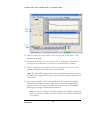
2 Lab MIAMI UNIVERSITY Mechanical Engineering Vibrations Laboratory Changing Experimental Parameters MIAMI UNIVERSITY VIBRATIONS LABORATORY Changing Experimental Parameters Miami University School of Engineering and Applied Science Department of Mechanical and Manufacturing Engineering 144 Kreger Hall Oxford, OH 45056 C H A N G I N G E X P E R I M E N T A L P A R A M E T E R S 2 Lab Changing Experimental Parameters of the Small Scale Road Vibration Simulator Objective The objective of the second laboratory is to analyze changes in the parameters of the system. The changes made in this experiment include using multiple accelerometers as well as adding weight to the system. By using multiple accelerometers, the user can compare the vibrations felt in different parts of the car, specifically in terms of the transfer function. By adding weight and changing the mass of the car, the user can explore the effects of a design change that could be implemented in a real world situation. Equipment List • MB Dynamics Modal 50A electrodynamic shaker • Amplifier • Amplifier connection cord • Shaker Accessories 1 C H A N G I N G E X P E R I M E N T A L P A R A M E T E R S o Tool kit o Cooling system o Stinger • Alro Racing TKTjunior 1/5th scale car • Support Structure o 4 bungee cords • 4 Accelerometers (varying sizes) • 4 Accelerometer connecting cords (black for small accelerometers, white for larger accelerometers) • Glue gun and sticks • Computer running GUI • Laptop running Signal Calc Ace • DAQ software • Signal conditioning board • Set of Precision Weights Procedure: Using Multiple Accelerometers 1) Setup the preliminary experimental setup as outlined in the User Manual section entitled ‘Experimental Setup’. Make sure to follow safety considerations. 2) Attach output measuring accelerometers according to the instructions on how to attach the accelerometer see the “Experimental Setup’ portion of the User Manual. a) Attach accelerometers to labels A1, A2, and A3 on the car. Be sure that the cords from the three accelerometers are connected to channel 1, channel 2, and channel 3 respectively. The two black cords are for the 2 Comments: C H A N G I N G E X P E R I M E N T A L P A R A M E T E R S small accelerometers and the two white cords are for the larger accelerometers. Note: Make sure the accelerometer is attached with wax in a perpendicular direction to the surface of the car. Be sure to use the black cords for the small accelerometers and the white cords for the large accelerometers. 3) Open Matlab 6.5 located on the desktop of the vibrations laboratory computer. 4) The corresponding GUI will popup automatically. It is called “working with hardware” GUI 5) On the laptop, double click the ‘SignalCalcAce’ icon located on the desktop. 6) Choose: fileÆopen new. 7) Choose ‘auto power spectra.’ A new window will open. 8) On the bottom left corner of the window, click the ‘generator’ tab. 9) Click ‘active’ box on the first line of information. 10) Choose ‘random’ waveform from the ‘waveform’ pulldown menu. 11) On the left side of the screen, make sure the F-span value is 1000. This sets the frequency range for the data. 12) On the left side of the screen, make sure the ‘lines’ value is the highest it can be. (i.e. move the sliding bar all the way to the right.) Note: See screen shot below for help on finding these sections of Signal Calc Ace. 3 Comments: C H A N G I N G E X P E R I M E N T A L P A R A M E T E R S 13) Click the dark green ‘Init’ button on the top left part of the screen. This initializes the program. 14) The program will ask you to save your data. Do so at this point. The name of the file you choose and where you choose to save the data does not matter. 15) Click the light green ‘start’ button on the top left part of the screen. This generates the signal which will be used to start the shaker. Note: The signal will be generated the entire time during the experiment, however, if it needs to be stopped, click the yellow ‘stop’ button located in the upper left area of the screen. 16) Turn on the amplifier. Slowly and carefully turn the knob on the amplifier. This will start the shaker in motion. Make sure not to turn the amplifier up too quickly or too far. To begin, turn it till two bars can be seen on the amplifier. Before going any higher, consult with the instructor. Note: If you hear a rattling sound while turning up the amplifier this probably means the stinger has broken out of the hot glue on the chassis and will need to be reglued. 4 Comments: C H A N G I N G E X P E R I M E N T A L P A R A M E T E R S 17) On the GUI highlight the ‘Enter duration here’ text in the sample duration text box and enter sample duration (2-5 seconds) for the experiment. This is the time that the Data Acquisition System is taking data for. 18) Click the ‘push me’ button on the GUI to begin data acquisition and analysis. 19) Wait a few moments (time equivalent to the sample duration entered) and the graphs related to the data acquisition and analysis will appear on the GUI. 20) Turn down gain on amplifier and then turn off amplifier. 21) Make sure to print these graphs. If needed, use the zoom capability being sure to follow the instructions found in the User Manual. Note: Use Alt+PrintScreen to copy the screen, then open a Word document and paste the graph, then save to desktop. Since you cannot access your M drive from this computer you will need to email this file to yourself to print later. 22) Close Matlab and SignalCalc Ace. Procedure: Adding Mass to System 1) Take off accelerometers A2 and A3 and unplug corresponding cords (channel 2, 3). 2) Follow steps 3-22 above to obtain a transfer function for the system with original mass. 3) Loosen stinger at base to allow it to adjust downward in response to the added weight. If the glue breaks, be sure to reglue. 4) Add the 500g mass to the front section of the car labeled M1. 5) Follow steps 3-22 above to obtain a transfer function of the system with added weight. 6) Remove the 500g mass from the car. 7) Loosen stinger at base to allow it to adjust downward in response to the added weight. If the glue breaks, be sure to reglue. 5 Comments: C H A N G I N G E X P E R I M E N T A L P A R A M E T E R S 8) Add the 1kg mass to the front section of the car labeled M1. If necessary, the black arms can be moved out of the way so that the weight is sitting on the chassis. 9) Follow steps 3-22 above to obtain a transfer function of the system with added weight. 10) Remove the 1kg weight from the car. 11) Loosen stinger at base to allow it to adjust downward in response to the added weight. If the glue breaks, be sure to reglue. 12) Add the 1kg mass to the front section of the car labeled M1. 13) Add the 500g mass to the back section of the car labeled M2. 14) Follow steps 3-22 above to obtain a transfer function of the system with added weight. 15) Remove the masses and place them carefully back in the box from which they came. 16) Use the “Dismantling Experiment” instructions found in the user manual. Lab Report Write up a lab report following the outline listed below: 1) Title Page: Include name, title of lab, date, semester information 2) Objectives: A brief explanation of the purpose of the experiment 3) Data: If graphs are produced, use a screenshot as a printout. If needed, use the zoom capability being sure to follow the instructions found in the User Manual. Note: Use Alt+PrintScreen to copy the screen, then open a Word document and paste the graph, then save to desktop. Since you cannot access your M drive from this computer you will need to email this file to yourself to print later. 4) Conclusions: Make sure to discuss the following Post Lab Discussion Topics 6 Comments: C H A N G I N G E X P E R I M E N T A L P A R A M E T E R S Post Lab Discussion Topics 1) Compare the transfer functions of the three accelerometers. Note the differences and similarities. Do the three have same resonant frequency peaks? What does this mean and how does it affect the possibilities for system design changes? 2) Compare the transfer functions obtained in the procedure “Adding Mass to System.” This is a comparison of the system with and without added weight. Note the differences and similarities. Based on these results how could one change the design of a car to lower its resonant frequencies. 7 Comments: 8


![[English] 1 MB](http://vs1.manualzilla.com/store/data/005724727_1-d0907da86b06d0402fef0dce028404c5-150x150.png)