1
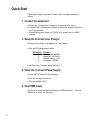
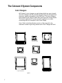
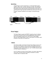
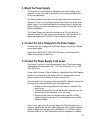
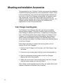
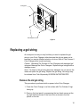
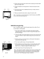
Colorchanger User Manual
4520 - 4 Inch Coloram II Color Changer
7110 - 7.5 Inch Coloram II Color Changer
7080 - 7.5 Inch Aquaram Color Changer
10100 - 10 Inch (2K) Coloram II Color Changer
15010 - 15 Inch (5K) Coloram II Color Changer
16080 - 8 Light Coloram II Color Changer
16090 - Large Format Coloram II Color Changer
16100 - Thomas 9 Light Coloram II Color Changer
5000 - Large Format Aquaram Color Changer
Software versions: CR1.0, LF1.0 and AR1.0
Manual revision: April 9, 2001
CONTENTS
Safety Information....................................................... 3
Introduction ................................................................. 3
The Coloram II System ............................................... 4
Quick-Start.................................................................. 5
Using The Coloram II Color Changer ......................... 6
The Coloram II System Components ......................... 7
Color Changer ....................................................... 7
Gelstring ................................................................ 8
Power Supply ........................................................ 8
Cables ................................................................... 8
Installing The Coloram II............................................. 9
Head-Feet Restrictions ............................................. 13
Mounting and Installation Accessories ..................... 15
Replacing a gelstring ................................................ 16
Equipment Compatibility ........................................... 18
Cables....................................................................... 19
Specifications............................................................ 20
Parts list .................................................................... 23
Warranty information ................................................ 24
Gelstring order form.................................................. 25
2
SAVE THESE INSTRUCTIONS
READ AND FOLLOW ALL INSTRUCTIONS
IMPORTANT SAFETY INSTRUCTIONS
This manual gives step-by-step instructions for preparation,
setup and operation of The Coloram II Power Supply.
There is a potential risk of fire, electric shock or injury to persons
if the product is not used as instructed.
The Coloram power supply is to be used in an indoor
environment only and is not intended for residential use.
The Coloram color changers are not intended for residential use.
Introduction
The Coloram II System is a scrolling Color Changer and Power Supply
in a complete range of models offering ease of setup and use. Its
variable color capacity and DMX compatibility affords the designer
economy and versatility, particularly when budget and space are
limited. The lightweight Color Changers slide easily into the gel frame
holder of the light fixture. The compact Power Supplies attach
effortlessly to the truss of the lighting rig or mount into a 19-inch rack.
This manual gives step-by-step instructions for preparation, setup and
operation of The Coloram II Color Changer.
3
The Coloram II System
The Coloram II System consists of one or more Color Changers and a
remote Power Supply. The DMX512 control signal from the lighting
board is connected to the Power Supply and can continue on to more
Coloram II Power Supplies or other DMX-controlled devices. The
Power Supply sends both power and control signal on a single cable
eliminating the need for a separate power cable for each Color
Changer.
The Coloram II System also allows you to control the Color Changer fan
speed via an additional DMX channel on the lighting console.
The Coloram II System is equipped with the Intelligent Diagnostic
System (IDS). Status information is sent from each of the Coloram
Color Changers to the Coloram Power Supply. The Power Supply in
turn transmits the information along pins 4 and 5 of the DMX cable to
The Watchdog Status Monitor. The Watchdog then displays Color
Changer status information at your lighting console.
Caution: The Coloram II System is not compatible with The Forerunner
System. Do not connect Coloram Color Changers to Forerunner Power
Supplies, or Forerunner Color Changers to Coloram Power Supplies.
Damage from such action will not be covered by the Coloram or
Forerunner warranties.
Coloram II
Color Changer
Coloram II
Power Supply
Coloram II
Color Changer
To additional
Color Changers
or Gobo Changers
Goboram Gobo Changer
AC Power
To additional
Color Changers
or Gobo Changers
Buffered
DMX512
To additional
Color Changers
or Gobo Changers
DMX Control console
To additional
Coloram Power Supplies
DMX CONSOLE
DMX512
Figure 1
4
Quick-Start
Follow these steps to get the Coloram II color changer operational
quickly.
1. Connect the equipment
a. Attach the Coloram color changer to a powered light fixture.
b. Connect the Coloram color changer to the power supply using the 4
pin Coloram cable.
c. Connect the power supply to 115/230 VAC power and to a DMX
source.
2. Setup the Coloram Color Changer
Set the color changer to an address of 1 as follows:
a. Set the DIP switches as follows:
DIP switch
1
2
3
4
Position
motor speed: NORM
operation: 24 CHAN
channel range: 1-12
fan speed: NORM
b. set the rotary "channel select" switch to 1
3. Setup the Coloram II Power Supply
Use the SETUP menu for the following:
a. Set the starting channel to 1.
b. Set the mode to CR2.
4. Send DMX levels
The Coloram color changer will respond to DMX channel 1. Vary the
DMX level to move the gel string.
5
Using The Coloram II Color Changer
The Coloram II Color Changer sets its gel string position according to
the DMX512 level it receives from the control console. As all Coloram II
Color Changers will accommodate variable length gel strings, the level
settings which correspond with each frame position will vary depending
on the number of frames in the gel string.
The following chart shows the level settings that correspond with each
frame position if a 24 frame gel string is installed on a 7.5 inch Color
Changer. The color of each frame position will be determined by your
custom gel string specification.
Channel
Level
Frame
Position
Channel
Level
Frame
Position
00
04
09
12
17
21
25
29
34
38
42
47
Frame 1
Frame 2
Frame 3
Frame 4
Frame 5
Frame 6
Frame 7
Frame 8
Frame 9
Frame 10
Frame 11
Frame 12
51
55
59
64
69
73
78
82
87
91
96
FL
Frame 13
Frame 14
Frame 15
Frame 16
Frame 17
Frame 18
Frame 19
Frame 20
Frame 21
Frame 22
Frame 23
Frame 24
If you send a channel level that is between the values shown, you can
create split frame effects. For example, if you send a level of 49, the
Color Changer positions the gel string halfway between frame 12 and
frame 13 creating a blend of the two colors.
Note: If you wish to use gel strings longer than 24 colors, Wybron
recommends the use of a moving light console. This gives the operator
more accurate control of the gel string position.
6
The Coloram II System Components
Color Changers
All Coloram II color changers use gel strings which can vary in length.
The color changers set the position of the gel string via the signal from
the power supply in proportion to the DMX level. The color changers
are powered by 24 volts DC which also comes from the Power Supply.
The control signal and DC power are both supplied in one cable
connecting the color changers to the Power Supply.
Note: Refer to the Specifications section of this manual for the
maximum number of gel string frames each Color Changer will hold
4 Inch Color Changer
15 Inch Color Changer
Large Format Color Changer
7.5 Inch Color Changer
10 Inch Color Changer
7.5 Inch Aquaram
Large Format Aquaram
8 Light Color Changer
Figure 2
7
Gel string
The gel string is a series of precisely cut, colored gel frames joined
together, side by side, to create a sequence of colors. Two additional
gels at each end of the gel string are called the leader and the trailer.
The leader and the trailer allow for proper attachment to the rollers. The
gel string has foil tags near each end which are necessary for the Color
Changer’s automatic calibration to the length of that particular gel
string.
Trailer
Frame 32
Frame 31
Long foil tag
Frame 2
Frame 1
Leader
Short foil tag
Figure 3
Power Supply
The Power Supply converts the DMX512 signal level from the lighting
console into Coloram/Coloram II control signal which it then sends to
each Color Changer along with 24 volts DC. The Power Supply
features a DMX bypass relay to pass the DMX signal to the DMX output
connector in the event of AC power loss.
Cables
The Coloram cable connects the Coloram Power Supply outputs to the
Coloram Color Changers or Goboram Gobo Changers and provides
them with power and control signal. The Coloram cable uses 4-pin XLR
connectors on either end and consists of two 14 AWG conductors and
a 22 AWG twisted, shielded pair.
Note: The cable used in the Coloram System is the same cable which is
used in the Forerunner System and may be referred to as either
Coloram cable or Forerunner cable.
8
Installing The Coloram II
To get your Coloram II System up and running, follow these hookup
and checkout procedures.
1. Attach the Color Changer to the fixture
Slide the Color Changer’s mounting bracket into the gel frame holder of
your lamp and lock the gel frame retention clip (if available). If the
mounting plate installed on your Color Changer doesn’t fit the fixture,
you may replace it with a different plate.
The mounting plate allows you to position the Color Changer with the
gel string rolling either horizontally or vertically. However, Coloram II
operates most effectively with the fan, which is located in the top of the
center panel, blowing air vertically (as hot air naturally rises).
2. Attach the safety cable
A safety cable is attached to the Color Changer. Run this cable around
the pipe or truss from which you hang the light fixture and clip it to itself.
Safety cable
Figure 5
9
3. Mount the Power Supply
The Coloram II Power Supply is designed to be free standing, truss
mounted, or rack mounted. You decide which mounting method best
suits your application.
The Power Supply comes with a mounting bracket which hooks over
the pipe or truss of your lighting rig and is then locked into place with a
thumb screw. If you have selected this mounting method, connect the
safety cable by running it around the pipe or truss to which the Power
Supply is attached.
The Power Supply can also be mounted into a 19" rack using the
optional Coloram II Power Supply rack mount kit. The rack mount kit
will accommodate two Coloram II Power Supplies side by side.
4. Connect the Color Changers to the Power Supply
Connect the Color Changers to the Power Supply using 4-pin Coloram
power/signal cable.
Refer to the HEAD-FEET RESTRICTION section of the manual for
details of the length of cable runs.
5. Connect the Power Supply to AC power
Plug the AC cord into a non-dimmed power circuit. The power supply
automatically accommodates 100 - 132 VAC (50/60 Hz) or 170 - 240
VAC (50/60 Hz).
Power at the Coloram II Power Supply is indicated by a red LED display
which can be viewed from the stage. Power is also indicated on the
bottom of each Color Changer by a red or yellow LED.
The connected Color Changers will automatically "calibrate" themselves
to the gel string installed by doing the following actions:
1. Moving the gel string toward the last frame, in search of the
long foil tag.
2. Turning around at the long foil tag and then searching for the
short foil tag at the beginning of the gel string.
3. Stopping at the short foil tag and staying there if no DMX
signal is present or going to it’s commanded position if DMX
signal is present.
Note: It may take up to 30 seconds before all Color Changers start to
initialize. Upon power up, the Power Supply will scroll a short message
which includes the software version installed in it. The Power Supply
will then initiate a "roll call" which tells the Color Changers to initialize.
10
Caution: Do not power the Power Supply from a dimmer. Severe
damage will result and is not covered by product warranty.
6. Set the Power Supply/Color Changer channels
Each Color Changer is assigned a DMX channel to which it will respond
from the lighting console. Valid DMX addresses are 001 - 512.
First, set the first channel for the block of DMX channels chosen for the
power supply -- do this on the power supply. Then, set the color
changer (the rotary switch and third DIP switch) for the first, second, etc
channel of the block of power supply channels.
For example, if you want a color changer to respond to DMX channel
105, first set the power supply channel block to start on channel 105
and then set the color changer to channel 1-- the first channel in the
block of power supply channels.
Set the power supply starting DMX channel by using the SETUP menu.
If talkback is enabled on the power supply, the starting power supply
channel is limited to 1, 4, 7, 10, 13, etc.
The rotary switch window is the channel indicator. The color changer
switch settings and the 24 channels they represent are as follows:
11
Rotary Switch
DIP Switch #3
Color Changer channels
1
2
3
4
5
6
7
8
9
A
B
C
1
2
3
4
5
6
7
8
9
A
B
C
Off
Off
Off
Off
Off
Off
Off
Off
Off
Off
Off
Off
On
On
On
On
On
On
On
On
On
On
On
On
1
2
3
4
5
6
7
8
9
10
11
12
13
14
15
16
17
18
19
20
21
22
23
24
The formula for calculating DMX channels is as follows:
DMX channel = Color Changer channel + Power Supply starting channel -1
Example: DMX channel (221) = Color Changer channel (20) + Power
Supply starting channel (202) -1
Note: For the 24 way power supply, the Coloram II color changers can
only be addressed to the first 24 channels of the 48 channel block of
the power supply.
Note: The Color Changers will not respond to the DMX signal until you
return in the "menu tree" to the RUN SCREEN loop.
7. Set The Coloram II operating modes
The Coloram II System offers you optional settings so you can custom
tailor it’s performance to best suit your application. These settings are
accessed via the 4 DIP switches on the bottom of each Color Changer
in combination with the Power Supply. To set the DIP switch, press the
switches in the direction of the words shown on the chassis legend.
The functions and indications of the LEDs and DIP switches on the
Color Changer are as follows:
LED On
Indicates
DIP Switch
Yellow
Red
Red
Green
Low Motor Speed
Low Voltage (< 22V)
Normal Motor Speed
Low Fan Speed
1
2
3
4
Function
Motor Speed
12/24 Channel Mode
Channel Range
Fan Speed
All Flashing Shutdown (< 15V or no
tags detected)
Fan speed (when enabled at the power supply) is remotely controlled
with the following DMX levels:
51% to 100% = fan at normal (high) speed
0% to 50% = fan at low speed
8% = fan off (when this function is enabled at the power supply)
Note: DIP switch 4 (Fan Speed) set to "Remote" allows the operator to
control the fan speed via the lighting console.
Note: The 12/24 channel mode is used to support either the original 12
Channel Coloram I Color Changers/Power Supplies (CR1) or the 24
channel Coloram II Color Changers/Power Supplies (CR2). All Color
Changers in a system must be set to the same mode as the Power
Supply to function correctly.
12
FAN SPEED NORM
REMOTE XTROL
24 CHAN
CHANNEL
SELECT
7110
MOTOR SPEED - NORM
OPERATION - 12 CHAN
CHANNEL RANGE 1 - 12
REMOTE XTROL
MADE IN USA
LOW MOTOR SPEED
NORM MOTOR SPEED
LOW VOLTAGE
LOW FAN SPEED
WYBRON, INC.
COLORADO SPRINGS, CO
13 - 24
Operating mode DIP switches
8
0
12
otary Switch
Indicator LEDs
Figure 9
8. Connect and set the DMX512 source
Connect the DMX512 signal source to the DMX input connector on the
front of the Power Supply using standard DMX cable. Valid DMX signal
will be indicated by the words "DMX OK" on the Power Supply display.
The Color Changers will now position their gel strings according to their
respective DMX signal levels.
Head-Feet Restrictions
The HEAD-FEET parameter is a method of accounting for the voltage
drop in the power/signal cable caused by the current drawn by each
color changer.
To help understand this issue, think of it as water pressure (voltage) in
a hose (cable) where you have multiple water sprinkler heads (color
changers). If the hose (cable) is too long or you have too many
sprinkler heads (color changers), the water pressure (voltage) will be
too low.
HEAD-FEET is defined as "the sum of cable lengths from each color
changer to a single power supply output".
13
Head-Feet Example:
Coloram
Power Supply
1
100’
20’
4
3
2
20’
Coloram II
Color Changer
20’
Coloram cable
Figure 8
The length of cable from the Power Supply to:
1st Coloram
2nd Coloram
3rd Coloram
4th Coloram
100’
120’
140’
160’
520 "head feet"
The maximum HEAD-FEET for each of the Coloram II color changers is
as follows:
(If a daisy chain consists of different models, use the model with the
least amount of "head feet" for the calculation).
4520 - 4 Inch Coloram II: 1500 head feet
7110 - 7.5 Inch Coloram II: 1500 head feet
7080 - 7.5 Inch Aquaram: 1000 head feet
10100 - 10 Inch Coloram II: 1000 head feet
15010 - 15 Inch Coloram II: 1000 head feet
16080 - 8 Light Coloram II: 1000 head feet
16090 - Large Format Coloram II: 1000 head feet
16100 - Thomas 9 Light Coloram II: 1000 head feet
5000 - Large Format Aquaram: 1000 head feet
14
Mounting and Installation Accessories
The components of your Coloram II System may require the installation
of additional mounting accessories or the replacement of others. Some
of these accessories, such as the Power Supply hanger brackets and
your choice of one Color Changer mounting plate, are supplied, while
other accessories, such as the Power Supply rack mount kit and
additional mounting plates, may need to be purchased separately. The
following sections describe the procedures for installation and
replacement of some of these accessories
Color Changer mounting plate
The Coloram II Color Changer ships with your choice of available
mounting plates installed. It may be necessary, when mounting the
Color Changer on different light fixtures, to replace the mounting plate.
Note: Some fixtures which require larger versions of Coloram II Color
Changers use multiple piece mounting assemblies. Some pieces of
these mounting assemblies may have to be attached directly to the
fixture and some may attach in a different manner than described below
to the Color Changer.
Follow these instructions to replace the mounting plate on 4 inch
through 10 inch Color Changers.
1. Place the Color Changer on a flat surface, with The Coloram II logo
face down.
2. Unscrew the four screws which hold the current mounting plate on.
3. Place the replacement mounting plate on the Color Changer,
aligning the screw holes properly.
4. Fasten the four corners of the mounting plate to the Color Changer
using the same screws you removed in step 2.
Note: Always use the supplied screws, as they are treated with an antivibration compound to keep them from loosening.
15
ounting plate
Mounting plate screws
Figure 12
Replacing a gel string
At some point in time you may find that you need to replace the gel
string in your Color Changer, either because the old one wears out or
because you want a different selection of colors. With all The Coloram II
Color Changers this is quick and easy.
Caution: Operating The Coloram II Color Changers with damaged gel
strings will damage the Color Changers. Replace the gel strings before
damage occurs.
Note: If a frame in the gel string becomes damaged, do not remove the
frame and splice the gel string. Replace the gel string. Gel strings may
be ordered from Color Express by WYBRON INCORPORATED.
Remove the old gel string
This procedure is performed with no power to the Color Changer.
1. Place the Color Changer on a flat surface with The Coloram II logo
facing up.
2. Remove the front panel by unscrewing the two thumb screws at the
top right and left corners of the front door as shown in the first
picture on the left.
16
3. Gently roll the gel string onto the left roller, exposing the clear leader
taped on the right roller.
4. Untape the leader from the right roller. Remove the tape from the
leader.
Left roller
(Drive roller)
Right roller
(Spring Roller)
5. Roll the gel string onto a cardboard tube as you slowly remove it
from the left roller.
6. When you reach the clear trailer, untape it from the roller.
Hint: To save time, move all gel strings to the first frame via the DMX
source before disconnecting power.
Figure 14
Install the new gel string
Note: Use gaffer’s tape to attach the gel strings to the rollers. Do not
use duct tape or masking tape.
1. Put a strip of gaffer’s tape on the edge of the gel string trailer.
Holding the trailer, let the rest of the roll hang off the right side of
the Color Changer.
2. Center the edge of the trailer between the two ends of the left roller
as shown to the left. Tape the trailer along the top of the roller as
shown.
3. Roll the gel string onto the left roller until the end of the leader is
directly above the right roller.
Gaffer’s tape
Last frame
4. Put a strip of gaffer’s tape on the gel string leader.
5. While holding the end of the gel string, turn the right roller toward
the left roller. The sticker at the bottom end of the roller has a
black line on it to help you judge the number of turns.
6. Tape the gel string to the right (spring) roller.
railer
Figure 15
17
Note: Use maximum number of spring roller turns for gel strings with
maximum number of frames. Use less turns for shorter gel strings.
Refer to the gel string tension chart below for the exact number of
turns for your Color Changer/gel string combination.
Models: 4520, 7110, and 7080
2 - 10 frames
11 - 18 frames
19 - 26 frames
27 - 32 frames
Number of Turns
5
6
7
8
Model: 10100
2 - 5 frames
6 - 10 frames
11 - 17 frames
18 - 24 frames
Number of Turns
5
6
7
8
Models: 15010, 16080, 16090, 16100, and 5000
2 - 4 frames
5 - 8 frames
9 - 12 frames
13 - 16 frames
17 - 20 frames
21 - 24 frames
Number of Turns
8
9
10
11
12
13
Equipment Compatibility
The following is a chart of compatibility and capacity of the various models of
Coloram power supply and the companion components.
Power Supply Model
Description Number
6 way
12 way
24 way
19060
19012
19000
Output
Power
150 watts
300 watts
600 watts
Max # of
Channels Max # of Max # of
Max # of
Max # of
Available CXI (2) Coloram (3) Eclipse (4) Goboram (5)
12
24
48
3
6
12
6
12
24 (1)
6
12
24 (1)
4
8
16
Notes:
(1) can only use the first 24 channels
(2) CXI’s use 1, 2 or 3 channels
(3) Coloram’s use 1 channel
(4) Eclipse’s use 1 channel
(5) Goboram’s use 3 channels
18
Cables
Coloram cable
The Coloram cable uses 4-pin XLR connectors on either end and
consists of two 14 AWG conductors and a 22 AWG twisted, shielded
pair. The shells of the two XLR connectors are not electrically
connected -- this prevents high power currents from flowing from
chassis to chassis of the Coloram equipment. The twisted pair shield is
not connected at either end.
XLR Pin #
1
2
3
4
Wire Color
White
Green
Red
Black
Function
24 Volts DC
Data Data +
Ground
Size
14 AWG
22 AWG
22 AWG
14 AWG
DMX512 control cable
The DMX control cable from the lighting board to the Power Supply is a
five conductor cable with 5-pin XLR connectors on each end. The
wiring pin out is specified by the USITT DMX512 / 1990 standard.
XLR Pin #
1
2
3
4
5
19
Function
Common
Data Data +
Talkback Talkback +
Specifications
The Coloram II Color Changer Technical Information
End to end speed:
3.2 seconds
Models:
4520, 7110, and 7080
5 seconds
Models:
10100, 15010, 16080, 16090, 16100, and 5000
Fan: Multiple speed - normal
- limited
- off
Fuse:
1.5 Amp Slo Blo
Models:
4520, 7110, 7080, and 10100
2 Amp Slo Blo
Models:
15010, 16080, 16090, 16100, and 5000
Gelstring:
2 - 32 frames
Models:
4520, 7110, and 7080
2 - 24 frames
Models:
10100, 15010, 16080, 16090, 16100, and 5000
Coloram II address: 01 - 24
LED Indicators:
Motor speed
Low voltage
Fan speed
Shutdown (all flashing)
Power supply compatibility:
The Coloram II 6 Way Power Supply
The Coloram II 12 Way Power Supply
The Coloram II 24 Way Power Supply
Signal termination: Not required
Weight:
Models:
4520: 3.66 lbs./1.66 kg
7110: 4.2 lbs./1.9 kg
7080: 7.08 lbs./3.21 kg
10100: 4.96 lbs./2.24 kg
15010: 11.86 lbs./5.37 kg
16080: 14.24 lbs./6.45 kg
16090: 12.00 lbs./5.44 kg
16100: 14.18 lbs./6.43 kg
5000: 25.28 lbs./11.46 kg
20
The Coloram II Color Changer Fixture Compatiblity
Fixture compatibility with optional mounting plates:
Models:
4520 - 4 Inch Coloram II Color Changer
Source Four
Shakespeare 600
Other fixtures with 6.25" gel frames
7110 - 7.5 Inch Coloram II Color Changer
Source Four
Shakespeare 600
Other fixtures with 6.25" gel frames
Source Four PAR
PAR 64
Full size ellipsoidals
7080 - 7.5 Inch Aquaram Color Changer
Source Four
Shakespeare 600
Other fixtures with 6.25" gel frames
Source Four PAR
PAR 64
Full size ellipsoidals
10100 - 10 Inch Coloram II Color Changer
Source Four 5 degree
Source Four 10 degree
Various 2K
15010 - 15 Inch Coloram II Color Changer
Various 3K
Various 4K
Various 5K
4-light
16080 - 8 Light Coloram II Color Changer
Various 8-light
16090 - Large Format Coloram II Color Changer
Various 5K
9-light
Various cyc lights
16100 - Thomas 9 Light Coloram II Color Changer
Thomas 9-light
5000 - Large Format Aquaram Color Changer
Various 5K
Phillips Arena Vision
21
The Coloram II Gelstring Information
4 Inch Coloram II:
2 - 32 frames plus leader and trailer
Frame width: 8"
Frame height: 6 1/16"
Leader/Trailer: 9.5"
7.5 Inch Coloram II:
2 - 32 frames plus leader and trailer
Frame width: 10"
Frame height: 7 13/16"
Leader/Trailer: 9.5"
7.5 Inch Aquaram:
2 - 32 frames plus leader and trailer
Frame width: 10"
Frame height: 7 13/16"
Leader/Trailer: 9.5"
10 Inch Coloram II:
2 - 24 frames plus leader and trailer
Frame width: 13 1/2"
Frame height: 10 5/16"
Leader/Trailer: 9.5"
15 Inch Coloram II:
2 - 24 frames plus leader and trailer
Frame width: 20"
Frame height: 16 1/8"
Leader/Trailer: 9.5"
8 Light Coloram II:
2 - 24 frames plus leader and trailer
Frame width: 20"
Frame height: 26 5/16"
Leader/Trailer: 9.5"
Large Format Coloram II:
2 - 24 frames plus leader and trailer
Frame width: 24"
Frame height: 18 5/8"
Leader/Trailer: 9.5"
Thomas 9 Light Coloram II:
2 - 24 frames plus leader and trailer
Frame width: 24"
Frame height: 18 5/8"
Leader/Trailer: 9.5"
Large Format Aquaram:
2 - 24 frames plus leader and trailer
Frame width: 24"
Frame height: 18 5/8"
Leader/Trailer: 9.5"
22
Parts list
To order any of the following items, contact your authorized WYBRON dealer.
The Coloram II Color Changers and Power Supplies
4520 ........................4 Inch Coloram II
7110 ........................7.5 Inch Coloram II
7080 ........................7.5 Inch Aquaram
10100 ......................10 Inch Coloram II
15010 ......................15 Inch Coloram II
16080 ......................8 Light Coloram II
16090 ......................Large Format Coloram II
16100 ......................Thomas 9 Light Coloram II
5000 ........................Large Format Aquaram
19000 ......................Coloram II 24 Way Power Supply
19012 ......................Coloram II 12 Way Power Supply
19060 ......................Coloram II 6 Way Power Supply
The Coloram II mounting and installation accessories
452-01-03P .............6.25"/158.75mm mounting plate for 4 inch Color Changer
452-03-04................6.25"/158.75mm mounting plate for 7.5 inch Color Changer
704-01-03P .............7.5"/190.5mm mounting plate for 7.5 inch Color Changer
711-01-03P .............10"/254mm mounting plate for 7.5 inch Color Changer
1009-01-20P ...........12.125"/307.98mm mounting plate for 10 inch Color Changer
1009-01-21P ...........14.25"/361.95mm mounting plate for 10 inch Color Changer
SCRPH832037P .....3/8" pan head screws for mounting plate to Color Changer
SCRPH832050 .......1/2" pan head screws for mounting plate to Color Changer
1900-01-05P ...........24 Way Power Supply hanger bracket
715-01-03P .............6 Way and 12 Way Power Supply hanger bracket
SCRWC252075 ......Wing screw for Power Supply hanger bracket to pipe
SCRSC2520037 .....Socket cap screw for hanger bracket to Power Supply
The Coloram II System cable
7042-3.....................3’ power/signal cable
7042-5.....................5’ power/signal cable
7042-10...................10’ power/signal cable
7042-15...................15’ power/signal cable
7042-25...................25’ power/signal cable
7042-50...................50’ power/signal cable
7042-75...................75’ power/signal cable
7042-100.................100’ power/signal cable
23
Warranty information
WYBRON, INC. warrants to the original owner or retail customer that
for a period of one year from date of delivery of a portable system or
energization of a permanently installed system (up to a maximum of 18
months from delivery) its products will be free from defects in materials
and workmanship under normal use and service.
Warranty does not cover any product or part of a product subject to
accident, negligence, alteration, abuse, misuse or any accessories or
parts not supplied by WYBRON, INC.. Warranty does not cover
"consumable" parts such as fuses, lamps, or color media. WYBRON,
INC.’s warranty does not extend to items not manufactured by us.
Freight terms on warranty repairs are FOB WYBRON, INC. factory or
designated repair facility. Collect shipments or freight allowances will
not be accepted.
WYBRON, INC.’s sole responsibility under this warranty shall be to
repair or replace at WYBRON, INC.’s option such parts as shall be
determined to be defected on WYBRON, INC.’s inspection. WYBRON,
INC. will not assume any responsibility for any labor expended or
materials used to repair any equipment without WYBRON, INC.’s prior
written authorization . WYBRON, INC. shall not be responsible for any
incidental, general or consequential damages to property, damages for
loss of use, time, profits or income, or any other charges.
The owner’s obligations during the warranty period under this warranty
are to notify WYBRON, INC. at WYBRON, INC.’s address within one
week of any suspected defect, and return the goods prepaid to
WYBRON, INC. at their factory or authorized service center.
This warranty is contingent on the customer’s full and timely compliance
with the terms of payment set forth in said purchase order. This
warranty is expressly in lieu of any and all other warranties expressed
or implied including the warranties of merchantability and fitness for a
particular purpose and of other obligations and liabilities on our part.
The owner acknowledges that no other representations were made to
him or relied upon him with respect to the quality and function of the
goods sold.
This written warranty is intended as a complete and exclusive
statement of the terms thereof. Prior dealings or trade usage shall not
be relevant to modify, explain or vary this warranty. Acceptance of, or
acquiescing in, a course of performance under this warranty shall not
modify the meaning of this agreement even though either party has
knowledge of the performance and a chance to object.
24
Gelstring order form
Any combination of color filter manufacturer’s gels can be combined to
create a custom Coloram II gelstring. Please specify using the following
format.
Specify: (G) GAM, (L) Lee, (R) Rosco with the color number and the
color name.
Customer
Ship to
Purchase Order
Due Date
Color Changer Model
Frame
Quantity
Filter Mfgr./Color number
Color name
1
2
3
4
5
6
7
8
9
10
11
12
13
14
15
16
17
18
19
20
21
22
23
24
25
26
27
28
29
30
31
32
WYBRON, INC. - TEL 719-548-9774 - FAX 719-548-0432
Email: [email protected] - Visit us on the World Wide Web at http://www.wybron.com
25
WYBRON, INC. - TEL 719-548-9774 - FAX 719-548-0432
Email: [email protected] - Visit us on the World Wide Web at http://www.wybron.com