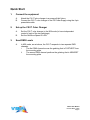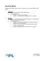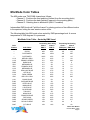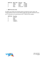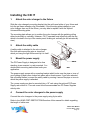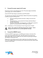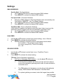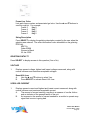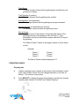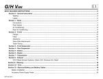
1
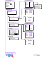
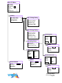
CXI IT User Manual 84560 87200 812210 816050 4-inch CXI IT 7.5-inch CXI IT 12-inch CXI IT Large Format CXI IT CXI IT software version: V1.2 Manual issue date: October 17, 2006 Manual revision: March 25, 2009 CONTENTS Safety Information ................................................................. 4 Introduction ........................................................................... 5 Quick Start ........................................................................... 6 Using CXI IT ......................................................................... 7 Operating Modes ............................................................. 7 Mix Mode Color Tables.................................................... 8 Mix Mode Color Table (sorted by DMX %) ...................... 8 Mix Mode Color Table (sorted by color number) ........... 10 Index Mode Color Table ................................................ 12 CXI IT System Components ............................................... 14 Color Changer ............................................................... 14 Gelstrings....................................................................... 14 Power Supply................................................................. 14 Cables............................................................................ 15 Installing the CXI IT............................................................. 17 CXI IT Menus ...................................................................... 19 Alerts/Error Messages....................................................22 DMX Address.................................................................24 Settings..........................................................................25 Sensor Info.....................................................................26 Self Test (Demo)............................................................28 History............................................................................28 Reset Defaults................................................................31 Head-Feet Restrictions ....................................................... 31 Loading a Gelstring ............................................................. 32 Power Supply Capacity ....................................................... 33 Non-RDM Equipment and Infotrace .................................... 33 Coloram IT Products and Standard Environments ............. 33 Specifications ...................................................................... 34 Parts List ............................................................................. 35 Warranty information........................................................... 36 CXI IT User Manual Revised March, 2009 Page 2 CXI IT User Manual Revised March, 2009 Page 3 Safety Information SAVE THESE INSTRUCTIONS READ AND FOLLOW ALL INSTRUCTIONS This manual gives step-by-step instructions for preparation, setup and operation of the CXI IT color changer. There is a potential risk of injury to persons if the product is not used as instructed. The CXI IT is not intended for residential use. WARNING: When using electrical appliances, use basic precautions, including: Read this manual before connecting power. Use supervision around children. Do not touch moving parts. Only use attachments recommended or sold by Wybron. Use in a dry location only. Replace only with same type and rating of fuse. For questions, contact Wybron at 1-800-624-0146. Product Modification Warning Wybron, Inc. products are designed and manufactured to meet the requirements of United States and International Safety standards. Modifications to the products could affect safety and render the product non-compliant to relevant safety standards. CXI IT User Manual Revised March, 2009 Page 4 Introduction The CXI IT color-mixing color changer offers a nearly limitless palette of colors by blending two overlapping gelstrings of cyan, magenta, and yellow, letting you create custom shades and tweak colors on the fly. Create custom colors, or replicate existing gels. The unit fits nearly every fixture available, sliding easily into a gel frame holder. A weather-resistant Mariner IT version is also available. Each CXI IT receives power and signal via Wybron’s PS Power Supply series. The unit is controlled by DMX512, and it sends feedback to its operators with Remote Device Management, an industry-standard feedback protocol. The CXI IT isn’t just RDM-compatible – it’s built with several sensors that collect a wealth of data, including gelstring temperature, fan speed, and lamp life. All this data gets send to the operator with Wybron’s RDM-based Infotrace feedback system, which makes it easy to remote address the devices, track maintenance cycles, and more. This manual gives step-by-step instructions for the preparation, setup, and operation of the CXI IT color changer. CAUTION: CXI IT color changers can ONLY be used with PS Power Supply units. Do not connect CXI IT units to Coloram II (RAM) Power Supplies. Do not connect Coloram II (RAM) units to PS Power Supplies. Damage from such action will not be covered by the product warranties. CXI IT User Manual Revised March, 2009 Page 5 Quick Start 1. Connect the equipment A. B. 2. Set up the CXI IT Color Changer A. B. 3. Attach the CXI IT color changer to a powered light fixture. Connect the CXI IT color changer to the PS Power Supply using the 4-pin power/data cable. Set the CXI IT color changer to the MIX mode (to have independent control of each of the two gelstrings). Set the Gel Move Speed to LOW. Send DMX Levels A. In MIX mode, as set above, the CXI IT responds to two separate DMX channels. i. The first DMX channel moves the gelstring that is FURTHEST from the mounting plate. ii. The second DMX channel positions the gelstring that is NEAREST the mounting plate. CXI IT User Manual Revised March, 2009 Page 6 Operating Modes Please refer to the Menu Details below for information on how to select INDEX or MIX mode. 1. Index mode A. Controls both gelstrings with ONE DMX channel. B. Channel descriptions: i. Channel 1: Positions both gelstrings ii. Channel 2: Gelstring time-to-destination (ONLY if enabled) 2. Mix mode A. Controls the two gelstrings with TWO DMX channels – with independent control of each of the two gelstrings. B. Channel descriptions: i. Channel 1: Positions the front gelstring (the gelstring located furthest from the mounting plate) ii. Channel 2: Positions the back gelstring (the gelstring located nearest the mounting plate) iii. Channel 3: Gelstring time-to-destination (ONLY if enabled) CXI IT User Manual Revised March, 2009 Page 7 Mix Mode Color Tables The MIX mode uses TWO DMX channels as follows: - Channel 1: Positions the front gelstring (furthest from the mounting plate) - Channel 2: Positions the back gelstring (nearest to the mounting plate) - Channel 3: Gelstring time-to-destination (ONLY if enabled) Intermediate DMX levels will "split the frames" by placing portions of two different colors in the aperture, letting the user create custom colors. The following table lists MIX mode colors sorted by DMX percentage level. A source temperature of 3200 degrees K is presumed. Mix Mode Color Table – Sorted by DMX Level Color Number Color Name ------L116 L139 G905 R83 R80 L132 R69 G740 L124 R90 L181 R383 G835 G810 L118 G690 G915 G760 G725 G685 G650 G945 G847 CLEAR CUSTOMER 2 CUSTOMER 1 MED BLU GRN PRIMARY GREEN DARK BLUE MEDIUM BLUE PRIMARY BLUE MEDIUM BLUE BRILLIANT BLUE OFF BLUE DARK GREEN DRK YELL GRN CONGO BLUE SAPPHIRE BLUE AZTEC BLUE MOON BLUE LIGHT BLUE BLUEGRASS TWILIGHT AQUA BLUE PRINCESS BLUE PISTACHIO GRASS GREEN ROYAL PURPLE CITY BLUE front string back string Chan 1 Chan 2 DMX % DMX % 49% 49% 100% 0% 0% 4% 4% 4% 4% 4% 4% 4% 4% 9% 9% 9% 9% 9% 9% 13% 13% 13% 13% 13% 18% 18% 45% 100% 45% 63% 95% 0% 4% 9% 13% 27% 31% 85% 90% 0% 4% 13% 18% 27% 54% 4% 31% 40% 63% 85% 0% 18% front string back string Chan 1 Chan 2 DMX (dec) DMX (dec) 125 125 255 0 0 10 10 10 10 10 10 10 10 23 23 23 23 23 23 33 33 33 33 33 46 46 115 255 115 161 242 0 10 23 33 69 79 217 230 0 10 33 46 69 138 10 79 102 161 217 0 46 CXI IT User Manual Revised March, 2009 Page 8 G815 R65 G710 G680 G660 R358 L180 G950 R64 R57 G940 L201 L117 R86 G960 G790 G995 G990 R52 R54 G540 R48 L203 L101 R344 R10 G450 R312 L104 G325 R09 R14 G155 G330 L204 R15 G160 G343 L179 L110 L105 R36 R318 G335 G130 L111 R23 G315 MOODY BLUE DAYLIGHT BLUE BLUE GREEN KELLY GREEN MED GREEN ROSE INDIGO DARK LAVENDER PURPLE LIGHT STEEL BLUE LAVENDER LIGHT PURPLE FULL CT BLUE STEEL BLUE PEA GREEN MEDIUM LAVENDER ELECTRIC BLUE ORCHID DARK LAVENDER LIGHT LAVENDER SPECIAL LAVENDER PALE GREEN ROSE PURPLE 1/4 CT BLUE YELLOW FOLIES PINK MEDIUM YELLOW SAFFRON CANARY DEEP AMBER BASTARD AMBER PALE AMBER GOLD MEDIUM STRAW LIGHT PINK SEPIA FULL CT ORANGE DEEP STRAW CHORUS PINK HONEY CHROME ORANGE MIDDLE ROSE ORANGE MEDIUM PINK MAYAN SUN CORAL ROSE DARK PINK ORANGE AUTUMN GLORY 18% 18% 18% 18% 18% 22% 22% 22% 22% 27% 27% 27% 27% 27% 31% 31% 36% 36% 36% 36% 36% 40% 40% 40% 45% 49% 54% 54% 54% 58% 58% 58% 63% 63% 63% 63% 67% 67% 67% 72% 72% 76% 76% 76% 81% 81% 81% 81% 22% 27% 36% 63% 81% 0% 4% 9% 22% 13% 18% 27% 36% 85% 18% 36% 4% 13% 22% 31% 67% 9% 40% 95% 9% 90% 85% 90% 95% 58% 72% 90% 54% 63% 85% 90% 54% 81% 90% 58% 95% 63% 81% 95% 54% 63% 90% 95% 46 46 46 46 46 56 56 56 56 69 69 69 69 69 79 79 92 92 92 92 92 102 102 102 115 125 138 138 138 148 148 148 161 161 161 161 171 171 171 184 184 194 194 194 207 207 207 207 56 69 92 161 207 0 10 23 56 33 46 69 92 217 46 92 10 33 56 79 171 23 102 242 23 230 217 230 242 148 184 230 138 161 217 230 138 207 230 148 242 161 207 242 138 161 230 242 CXI IT User Manual Revised March, 2009 Page 9 R44 R32 R22 G110 G120 G180 R19 L128 R39 R46 R26 MIDDLE ROSE MEDIUM SALMON PINK DEEP AMBER DARK ROSE BRIGHT PINK CHERRY FIRE BRIGHT PINK EXOTIC SANGRIA MAGENTA LIGHT RED 85% 85% 85% 90% 90% 90% 90% 95% 95% 95% 95% 54% 81% 95% 49% 58% 76% 95% 54% 58% 76% 95% 217 217 217 230 230 230 230 242 242 242 242 138 207 242 125 148 194 242 138 148 194 242 The following table lists MIX mode colors sorted by color number. Mix Mode Color Table – Sorted by Color Number Color Number ------G110 G120 G130 G155 G160 G180 G315 G325 G330 G335 G343 G450 G540 G650 G660 G680 G685 G690 G710 G725 G740 G760 G790 G810 G815 Color Name CLEAR CUSTOMER 2 CUSTOMER 1 DARK ROSE BRIGHT PINK ROSE LIGHT PINK CHORUS PINK CHERRY AUTUMN GLORY BASTARD AMBER SEPIA CORAL HONEY SAFFRON PALE GREEN GRASS GREEN MED GREEN KELLY GREEN PISTACHIO BLUEGRASS BLUE GREEN PRINCESS BLUE OFF BLUE AQUA BLUE ELECTRIC BLUE MOON BLUE MOODY BLUE front string back string Chan 1 Chan 2 DMX % DMX % 49% 45% 49% 100% 100% 45% 90% 49% 90% 58% 81% 54% 63% 54% 67% 54% 90% 76% 81% 95% 58% 58% 63% 63% 76% 95% 67% 81% 54% 85% 36% 67% 13% 85% 18% 81% 18% 63% 13% 63% 9% 54% 18% 36% 13% 40% 4% 31% 13% 31% 31% 36% 9% 18% 18% 22% front string back string Chan 1 Chan 2 DMX (dec) DMX (dec) 125 115 125 255 255 115 230 125 230 148 207 138 161 138 171 138 230 194 207 242 148 148 161 161 194 242 171 207 138 217 92 171 33 217 46 207 46 161 33 161 23 138 46 92 33 102 10 79 33 79 79 92 23 46 46 56 CXI IT User Manual Revised March, 2009 Page 10 G835 G847 G905 G915 G940 G945 G950 G960 G990 G995 L101 L104 L105 L110 L111 L116 L117 L118 L124 L128 L132 L139 L179 L180 L181 L201 L203 L204 R09 R10 R14 R15 R19 R22 R23 R26 R312 R318 R32 R344 R358 R36 R383 R39 R44 R46 R48 R52 AZTEC BLUE CITY BLUE DARK BLUE TWILIGHT LIGHT PURPLE ROYAL PURPLE PURPLE MEDIUM LAVENDER DARK LAVENDER ORCHID YELLOW DEEP AMBER ORANGE MIDDLE ROSE DARK PINK MED BLU GRN STEEL BLUE LIGHT BLUE DARK GREEN BRIGHT PINK MEDIUM BLUE PRIMARY GREEN CHROME ORANGE DARK LAVENDER CONGO BLUE FULL CT BLUE 1/4 CT BLUE FULL CT ORANGE PALE AMBER GOLD MEDIUM YELLOW MEDIUM STRAW DEEP STRAW FIRE DEEP AMBER ORANGE LIGHT RED CANARY MAYAN SUN MEDIUM SALMON PINK FOLIES PINK ROSE INDIGO MEDIUM PINK SAPPHIRE BLUE EXOTIC SANGRIA MIDDLE ROSE MAGENTA ROSE PURPLE LIGHT LAVENDER 9% 18% 4% 13% 27% 18% 22% 31% 36% 36% 40% 54% 72% 72% 81% 0% 27% 9% 4% 95% 4% 0% 67% 22% 9% 27% 40% 63% 58% 49% 58% 63% 90% 85% 81% 95% 54% 76% 85% 45% 22% 76% 9% 95% 85% 95% 40% 36% 13% 18% 0% 4% 18% 0% 9% 18% 13% 4% 95% 95% 95% 58% 63% 63% 36% 27% 85% 54% 13% 95% 90% 4% 0% 27% 40% 85% 72% 90% 90% 90% 95% 95% 90% 95% 90% 81% 81% 9% 0% 63% 4% 58% 54% 76% 9% 22% 23 46 10 33 69 46 56 79 92 92 102 138 184 184 207 0 69 23 10 242 10 0 171 56 23 69 102 161 148 125 148 161 230 217 207 242 138 194 217 115 56 194 23 242 217 242 102 92 33 46 0 10 46 0 23 46 33 10 242 242 242 148 161 161 92 69 217 138 33 242 230 10 0 69 102 217 184 230 230 230 242 242 230 242 230 207 207 23 0 161 10 148 138 194 23 56 CXI IT User Manual Revised March, 2009 Page 11 R54 R57 R64 R65 R69 R80 R83 R86 R90 SPECIAL LAVENDER LAVENDER LIGHT STEEL BLUE DAYLIGHT BLUE BRILLIANT BLUE PRIMARY BLUE MEDIUM BLUE PEA GREEN DRK YELL GRN 36% 27% 22% 18% 4% 4% 4% 27% 4% 31% 13% 22% 27% 27% 9% 4% 85% 90% 92 69 56 46 10 10 10 69 10 79 33 56 69 69 23 10 217 230 Index Mode Color Table The Index mode uses ONE DMX channel as follows: - Channel 1: positions the two gelstrings - Channel 2: gelstring time-to-destination (ONLY if enabled) The following table lists INDEX mode colors sorted by color number. A source temperature of 3200 degrees Kelvin is presumed. Index Color Table Color Number ------G110 G120 G130 G155 G160 G180 G220 G315 G325 G330 G335 G343 G450 G540 G570 G650 G655 G660 G680 G685 G690 G710 G725 Color Name DMX % DMX decimal front gelstring color back gelstring color CLEAR CUSTOMER 1 CUSTOMER 2 DARK ROSE BRIGHT PINK ROSE LIGHT PINK CHORUS PINK CHERRY PINK MAGENTA AUTUMN GLORY BASTARD AMBER SEPIA CORAL HONEY SAFFRON PALE GREEN LT GREEN YELLOW GRASS GREEN RICH GREEN MED GREEN KELLY GREEN PISTACHIO BLUEGRASS BLUE GREEN PRINCESS BLUE 0% 99% 100% 55% 63% 56% 59% 61% 48% 57% 41% 77% 76% 85% 80% 84% 73% 78% 67% 74% 69% 71% 72% 36% 37% 39% 0 252 255 140 161 143 150 156 122 145 105 196 194 217 204 214 186 199 171 189 176 181 184 92 94 99 CLEAR CUSTOMER 1 CLEAR MAGENTA 9 MAGENTA 9 MAGENTA 7 MAGENTA 3 MAGENTA 4 MAGENTA 9 MAGENTA 10 MAGENTA 7 MAGENTA 2 MAGENTA 3 MAGENTA 6 MAGENTA 4 MAGENTA 1 CYAN 3 CYAN 5 CYAN 8 CYAN 10 CYAN 7 CYAN 7 CYAN 8 CYAN 9 CYAN 7 CYAN 8 CLEAR CLEAR CUSTOMER 2 YELLOW 1 YELLOW 3 YELLOW 2 YELLOW 2 YELLOW 2 YELLOW 7 YELLOW 7 YELLOW 11 YELLOW 3 YELLOW 4 YELLOW 11 YELLOW 8 YELLOW 9 YELLOW 5 YELLOW 9 YELLOW 9 YELLOW 10 YELLOW 8 YELLOW 4 YELLOW 4 YELLOW 2 MAGENTA 2 MAGENTA 1 CXI IT User Manual Revised March, 2009 Page 12 G740 G760 G790 G810 G815 G835 G840 G847 G848 G850 G905 G915 G940 G945 G950 G960 G990 G995 L101 L104 L105 L110 L111 L116 L117 L118 L124 L128 L132 L139 L141 L161 L179 L180 L181 L201 L203 L204 R09 R10 R14 R15 R18 R19 R21 R22 R23 R26 R312 R318 R32 R3202 R344 R358 R36 R383 R385 R39 OFF BLUE AQUA BLUE ELECTRIC BLUE MOON BLUE MOODY BLUE AZTEC BLUE STEEL BLUE CITY BLUE BONUS BLUE BLUE DARK BLUE TWILIGHT LIGHT PURPLE ROYAL PURPLE PURPLE MEDIUM LAVENDER DARK LAVENDER ORCHID YELLOW DEEP AMBER ORANGE MIDDLE ROSE DARK PINK MED BLU GRN STEEL BLUE LIGHT BLUE DARK GREEN BRIGHT PINK MEDIUM BLUE PRIMARY GREEN BRIGHT BLUE SLATE BLUE CHROME ORANGE DARK LAVENDER CONGO BLUE FULL CT BLUE 1/4 CT BLUE FULL CT ORANGE PALE AMBER GOLD MEDIUM YELLOW MEDIUM STRAW DEEP STRAW FLAME FIRE GOLDEN AMBER DEEP AMBER ORANGE LIGHT RED CANARY MAYAN SUN MEDIUM SALMON PINK C.T. FULL BLUE FOLIES PINK ROSE INDIGO MEDIUM PINK SAPPHIRE BLUE ROYAL BLUE EXOTIC SANGRIA 21% 30% 26% 15% 34% 12% 33% 29% 22% 5% 1% 11% 40% 8% 31% 45% 44% 43% 88% 89% 97% 58% 62% 23% 24% 19% 70% 52% 10% 65% 14% 27% 90% 17% 3% 42% 25% 81% 79% 87% 86% 96% 83% 98% 94% 95% 92% 93% 91% 82% 53% 18% 51% 20% 64% 6% 2% 60% 54 77 66 38 87 31 84 74 56 13 3 28 102 20 79 115 112 110 224 227 247 148 158 59 61 48 179 133 26 166 36 69 230 43 8 107 64 207 201 222 219 245 212 250 240 242 235 237 232 209 135 46 130 51 163 15 5 143 CYAN 10 CYAN 8 CYAN 4 CYAN 9 CYAN 7 CYAN 9 CYAN 6 CYAN 7 CYAN 7 CYAN 10 CYAN 10 CYAN 8 CYAN 5 CYAN 7 CYAN 6 CYAN 4 CYAN 3 CYAN 3 CYAN 2 MAGENTA 1 MAGENTA 5 MAGENTA 5 MAGENTA 7 CYAN 11 CYAN 5 CYAN 9 CYAN 10 MAGENTA 10 CYAN 10 CYAN 11 CYAN 10 CYAN 7 MAGENTA 4 CYAN 6 CYAN 9 CYAN 5 CYAN 2 MAGENTA 3 MAGENTA 2 CLEAR MAGENTA 2 MAGENTA 3 MAGENTA 4 MAGENTA 9 MAGENTA 5 MAGENTA 8 MAGENTA 7 MAGENTA 10 MAGENTA 1 MAGENTA 6 MAGENTA 8 CYAN 5 CYAN 1 CYAN 6 MAGENTA 6 CYAN 9 CYAN 9 MAGENTA 10 MAGENTA 3 MAGENTA 3 MAGENTA 2 MAGENTA 6 MAGENTA 5 MAGENTA 7 MAGENTA 5 MAGENTA 6 MAGENTA 6 MAGENTA 9 MAGENTA 10 MAGENTA 9 MAGENTA 6 MAGENTA 10 MAGENTA 8 MAGENTA 6 MAGENTA 7 MAGENTA 9 YELLOW 11 YELLOW 11 YELLOW 11 YELLOW 3 YELLOW 4 YELLOW 4 MAGENTA 2 MAGENTA 4 YELLOW 9 YELLOW 2 MAGENTA 7 YELLOW 11 MAGENTA 4 MAGENTA 5 YELLOW 10 MAGENTA 9 MAGENTA 10 MAGENTA 4 MAGENTA 1 YELLOW 9 YELLOW 6 YELLOW 10 YELLOW 10 YELLOW 10 YELLOW 8 YELLOW 11 YELLOW 11 YELLOW 11 YELLOW 10 YELLOW 11 YELLOW 10 YELLOW 8 YELLOW 8 MAGENTA 4 MAGENTA 8 MAGENTA 10 YELLOW 4 MAGENTA 9 MAGENTA 10 YELLOW 3 CXI IT User Manual Revised March, 2009 Page 13 R44 R46 R48 R52 R54 R57 R58 R59 R64 R65 R68 R69 R80 R83 R86 R89 R90 MIDDLE ROSE MAGENTA ROSE PURPLE LIGHT LAVENDER SPECIAL LAVENDER LAVENDER DEEP LAVENDER INDIGO LIGHT STEEL BLUE DAYLIGHT BLUE SKY BLUE BRILLIANT BLUE PRIMARY BLUE MEDIUM BLUE PEA GREEN MOSS GREEN DRK YELL GRN 54% 49% 47% 46% 50% 38% 28% 7% 32% 35% 13% 16% 9% 4% 66% 68% 75% 138 125 120 117 128 97 71 18 82 89 33 41 23 10 168 173 191 MAGENTA 8 MAGENTA 10 CYAN 2 CYAN 3 CYAN 3 CYAN 5 CYAN 6 CYAN 7 CYAN 6 CYAN 7 CYAN 9 CYAN 10 CYAN 10 CYAN 10 CYAN 5 CYAN 7 CYAN 10 YELLOW 2 YELLOW 7 MAGENTA 8 MAGENTA 5 MAGENTA 3 MAGENTA 7 MAGENTA 9 MAGENTA 10 MAGENTA 5 MAGENTA 4 MAGENTA 7 MAGENTA 4 MAGENTA 8 MAGENTA 9 YELLOW 9 YELLOW 8 YELLOW 10 CXI IT System Components Color Changer The CXI IT color changer uses two pre-made gelstrings containing cyan, magenta, and yellow gel, with 23 frames in each gelstring. The color changer sets the position of the gelstring as determined by the DMX signal level. The color changer is powered by 24 volts DC, which also comes from the power supply. The DMX signal, RDM data, and DC power are all supplied in one cable connecting the color changers to the power supply. Power Supply The PS Power Supply sends the DMX512 signal level from the lighting console to each color changer along with 24 volts DC. RDM information is sent from the CXI IT color changer to the Infogate software installed on a Mac or PC. Gelstrings The two CXI gelstrings are a predetermined series of precisely cut, colored gel frames joined together, side-by-side, to create a sequence of colors. Gelstring #1 (front) includes colors in the magenta-cyan range, and gelstring #2 (back) covers the yellowmagenta color range. CXI IT User Manual Revised March, 2009 Page 14 Each gelstring features an RFID tag on the “custom color” frames (a custom color of gel chosen by the customer). The RFID tag contains information about the gelstring and send that information to the user via RDM and the Infotrace system. Two additional clear gel frames at each end of each gelstring are called the “leader” and the “trailer.” The leader and the trailer allow for proper attachment to the rollers. The gelstring has foil tags near each end; these tags are necessary for the color changer's automatic calibration to the length of that particular gelstring. Cables • Power/Data cable The 4-pin power/data cable connects the PS Power Supply outputs to the CXI IT color changers and provides them with power and control signal. The power/data cable uses 4-pin XLR connectors on either end and consists of two 14 AWG conductors and a 22 AWG twisted, shielded pair. The shells of the two XLR connectors are not electrically connected, preventing high-power currents from flowing from chassis to chassis of the Coloram IT equipment. The twisted pair shield is connected only at the male XLR connector end. This is the standard Wybron power/data cable. CXI IT User Manual Revised March, 2009 Page 15 XLR Pin # 1 2 3 4 • Wire Color White Green Red Black Function Ground Data Data + 24 Volts DC Size 14 AWG 22 AWG 22 AWG 14 AWG DMX512 control cable The DMX control cable from the lighting board to the dimmers, power supply, and Infogate gateway (if used) is a five-conductor cable with 5-pin XLR connectors on each end. The wiring pin-out is specified by the USITT DMX512/1990 standard. XLR Pin # 1 2 3 4 5 Function Common Data Data + Talkback Talkback + CXI IT User Manual Revised March, 2009 Page 16 Installing the CXI IT 1. Attach the color changer to the fixture Slide the color changer's mounting bracket into the gel frame holder of your fixture and lock the gel frame retention clip (if available). If the mounting plate installed on your color changer does not fit the fixture, you may able to replace it with the Wybron Universal Mounting plate. The mounting plate allows you to position the color changer with the gelstring rolling either horizontally or vertically. However, CXI IT operates most effectively with the fan, which is located in the top of the center panel, blowing air vertically (as hot air naturally rises). 2. Attach the safety cable A safety cable is attached to the color changer. Run this cable around the pipe or truss from which you hang the light fixture and clip it to itself. 3. Mount the power supply The PS Power Supply is designed to be free standing, truss mounted, or rack mounted. You decide which mounting method best suits your application. The power supply comes with a mounting bracket which hooks over the pipe or truss of your lighting rig and is then locked into place with a thumb screw. If you have selected this mounting method, connect the safety cable by running it around the pipe or truss to which the power supply is attached. The power supply can also be mounted into a 19" rack using the optional PS Power Supply rack mount kit. The rack mount kit will accommodate two PS Power Supplies side by side. 4. Connect the color changers to the power supply Connect the color changers to the power supply using 4-pin cable. Refer to the HEAD-FEET RESTRICTIONS section of this manual for details regarding the length of cable runs. CXI IT User Manual Revised March, 2009 Page 17 5. Connect the power supply to AC power Plug the AC cord into a non-dimmed power circuit. The power supply automatically accommodates 100 - 240 VAC (50/60 Hz). Power at the PS Power Supply is indicated by a red LED indicator. The connected color changers will automatically "calibrate" themselves to the gelstring installed by doing the following actions: a. b. c. Moving the gelstring toward the last frame, stalling on the end of the gelstring. Changing direction, moving toward the first frame and then stalling on the end of the gelstring. Stopping at the first frame and staying there if no DMX signal is present or going to its commanded position if DMX signal is present. Note: It may take up to 30 seconds before all color changers start to initialize. Caution: Do not power the PS Power Supply from a dimmer. Severe damage will result and is not covered by product warranty. 6. Connect the DMX512 source Connect the DMX512 signal source to the DMX input connector on the front of the power supply using standard DMX cable. Valid DMX signal will be indicated by a flashing green LED. The color changers will now position their gelstrings according to their respective DMX signal levels. Please refer to the Infogate manual for further details about how lighting fixtures and CXI IT color changers can be automatically paired together and remotely assigned DMX addresses using Infogate. CXI IT User Manual Revised March, 2009 Page 18 Main LCD Menu [Alerts Menu] [DMX Status] DMX Address: 512 Settings Sensor Info History Reset Defaults > CXI (IT) Graphical Menu Tree > > > > Alerts Menu This menu only displays when there is an active alert on the unit. DMX Status Displays status of incoming DMX signal. i.e. “No DMX Data” or “DMX Signal OK” Multiple Alerts Example GEL ALERT > Single Alert Example GEL ALERT FAN ALERT GELSTRING OUT OF POSITION - UNIT SHUT DOWN > Reset all Alerts? No/Yes Reset this Alert? No/Yes DMX Address Displays current DMX Address that can be selected and modified, using unit buttons. Note: The unit will remember its DMX Address when unplugged. Settings DMX Addresses Fan Speed Gel Move Speed Gel DMX Mode > > > > DMX Addresses Scroller Address Fan Speed Addr Time/Dest Addr 1 2 3 Fan Speed Options: High - default Low Remote - control remotely via assigned DMX channel Fan Speed FAN high SPEED Gel Move Speed GEL MOVE SPEED high TTD info Note: The unit only supports one secondary address at a time. You can have Fan Speed on a remote channel or Time To Destination (Time/Dest) on a remote channel but not both remotely controlled at the same time. > Gel Move Speed Options: High - default Low Time/Dest - control remotely via assigned DMX channel TTD info Gel DMX Mode index GEL MODE Continued next page… Time/Dest Addr Information 3 > Gel DMX Mode: Index – 1 address, preprogrammed color mixs Mix – 2 address, mix color Information Chart of information regarding time to destination remote settings. No changes can be made from this screen. TIME TO DEST INFO ONLY 95-100%: Hi 90-94%: Low 85-89%: 80 sec 80-84%: 70 sec 75-79%: 60 sec 70-74%: 50 sec 65-69%: 40 sec 60-64%: 35 sec 55-59%: 30 sec 50-54%: 25 sec 45-49%: 20 sec 40-44%: 15 sec 35-39%: 10 sec 30-34%: 9 sec 25-29%: 8 sec 20-24%: 7 sec 15-19%: 6 sec 5 sec CXI IT10-14%: User Manual 4 sec Revised5-9%: March, 2009 0-4%: ASAP Page 19 Main LCD Menu [Alerts Menu] [DMX Status] DMX Address: 512 Settings Sensor Info History Reset Defaults Gel Wear Gauge > GEL 1 WEAR GAUGE > > > > Replace Note: This gauge is maintained in the RFID Gelstring Tag. Not on the device. Frame # vs. Color Sensor Info Gel 1 String Info Gel 2 String Info Voltage Fan RPM New > > > > GEL 1 FRAME COLOR WC11 WC10 WC9 WC8 WC7 L181 String Description Gel 1 String Info Gel 1 Wear Gauge Frame # vs. Color String 1 Description #1 #2 #3 #4 #5 #6 > > > CXI Standard GEL 1 Front STR. Gelstring DESC. 10/2006 > > > Gel Wear Gauge Gel 2 String Info Gel 2 Wear Gauge Frame # vs. Color String 2 Description New GEL 2 WEAR GAUGE Voltage VOLTAGE Now = 23.6V(15V min) High = 23.7V(24V max) Low = 23.5V(15V min) Reset Hi & Low? No/Yes Fan RPM Fan RPM OK? Yes Replace Frame # vs. Color GEL 2 FRAME COLOR #1 #2 #3 #4 #5 #6 WM10 WM9 WM8 WM7 WM6 L27 String Description CXI Standard GEL 2 Back STR. Gelstring DESC. 10/2006 Continued next page… CXI IT User Manual Revised March, 2009 Page 20 Main LCD Menu [Alerts Menu] [DMX Status] DMX Address: 512 Settings Sensor Info History Reset Defaults > > > > > History Gel 1 String History Gel 2 String History Operating Hours Host Light Lamp > > > > Gel 1 String History Tot Time: 12hr Tot Moves: 549843 Tot Dist: 2813 met Avg Move: 0 cm Avg Vel: 21 cm/sec Max at frame: 3400 Gel 2 String History Tot Time: 12hr Tot Moves: 378241 Tot Dist: 2554 met Avg Move: 0 cm Avg Vel: 25 cm/sec Max at frame: 12700 Operating Hours RESET FACTORY DEFAULT SETTINGS? No/Yes SINCE CLEAN RESET: 287 HR Reset > Like New Needs Cleaning Cleaning Info > Maintenance Info > Lifetime Hours is 287 Reset Host Light Lamp RESET No/Yes CLEANING HOURS GAUGE? HOST LAMP HOURS: 16 HR 0 hrs Reset > 500 hrs Maintenance Info Reset Reset Defaults Cleaning Info RESET No/Yes HOST LIGHT LAMP HOURS GAUGE? SINCE MAINT RESET: 287 HR Reset > Like New Needs Maint. Reset RESET No/Yes MAINTEANCE HOURS GAUGE? CXI IT User Manual Revised March, 2009 Page 21 MENU DETAILS 1. 2. Use the and buttons to scroll through selections on the display. Press SELECT to activate that selection or progress to the next level of displays. Figure 5 The and buttons are also used to navigate to further levels within the display. For example, to select “Scroller Address”: 1. 2. 3. 4. 5. 6. Use the and buttons to move to the selection box to “Settings.” Press SELECT to select “Settings.” Use the and buttons to move to the selection box to “DMX Addresses.” Press SELECT to select “DMX Addresses.” Use the and buttons to move to the selection box to “Scroller Address.” Press SELECT to select “Scroller Address.” Alerts / Error Messages The following is an explanation of alerts and error messages that are displayed locally on the color changer. To read alert messages: 1. 2. 3. 4. When “SENSOR ALERT” is displayed, press SELECT. As an example: “VOLTAGE ALERT” indicates a voltage problem. Press SELECT to access more information on the Voltage Alert. For example: “WARNING – VOLTAGE DROPPED BELOW 15V” VOLTAGE ALERTS • “WARNING – VOLTAGE DROPPED BELOW 15V” Operating voltage has dropped below the minimum operating requirement of 15 volts. The cable between the CXI IT and the PS Power Supply may be too long. CXI IT User Manual Revised March, 2009 Page 22 • “VOLTAGE DROPPED BELOW 13V UNIT SHUTDOWN” Unit has automatically shut down because operating voltage has dropped below 13 volts for more than one second. The voltage typically drops this low if the cable is too long — the head-feet limit has been exceeded. GEL ALERTS 1. “GELSTRING OUT OF POSITION — UNIT SHUTDOWN” Scroller motor automatically shuts down if gelstring is not in its programmed frame position or a roller is stuck. 2. “GELSTRING DID NOT INIT PROPERLY” Gelstring did not initialize properly. Please check that gelstring is properly installed. 3. “GELSTRING IS BROKEN — UNIT SHUTDOWN” Scroller motor automatically shuts down if gelstring has broken or come loose from a roller. Gelstring needs to be replaced or reinstalled. MOTOR ALERT 1. “MOTOR IS OPERATING AT A HI CURRENT LEVEL” High current level at the scroller motor may indicate an ususually high level of friction at the motor. Please check scroller motor for possible maintenance or replacement. FAN ALERT 1. “FAN IS OFF WHILE THE LAMP IS ON” The color changer may overheat or premature fading of the gelstring colors may occur when the scroller fan is off while the fixture lamp is on. 2. “FAN IS NOT OPERATING PROPERLY” Check fan for possible maintenance. CXI IT User Manual Revised March, 2009 Page 23 RFID ALERTS 1. “RFID TAG — COMMUNICATION FAILURE” A. Communication could not be established with the RFID tag. B. Press SELECT for more detailed information: i. “COULD NOT WAKE THE RFID TAG” RFID wake command did not finish. ii. “COULD NOT READ THE RFID TAG” Coloram IT had a communication failure when trying to read the RFID tag. iii. “COULD NOT WRITE THE RFID TAG” Coloram IT had a communication failure when trying to write to the RFID tag. RESET ALERT Clears existing alert from display screen when you press SELECT, unless problem hasn’t been resolved and still exists. MULTIPLE ALERTS 1. 2. 3. 4. 5. 6. 7. Press SELECT to read the first alert. Press SELECT to read the details of the first alert. Press BACK to view the second alert. Press SELECT to view details of the second alert. Press BACK to check if there any additional alerts, repeat Steps 4 and 5 until all alerts have been read. Once all alerts have been read, use the d key to move the selection box to the “RESET ALL ALERTS” command. Press SELECT to clear all alerts, except for those that currently exist as problems. DMX Address 1. 2. Use the and buttons to select the desired DMX address. Press SELECT to activate the displayed DMX address. CXI IT User Manual Revised March, 2009 Page 24 Settings DMX ADDRESSES Scroller Addr (Scroller Address) A. Use the and buttons to select the desired DMX address. B. Press SELECT to activate the desired DMX address. Fan Speed Addr (Fan Speed Address) A. Selecting a DMX address for Fan Speed Address also automatically sets Fan Speed to “REMOTE” (see “Fan Speed” below). B. Use the and buttons to select the desired DMX address. C. Press SELECT to activate the desired DMX address. Time/Dest Addr (Time to Destination Address) If this function is enabled, this feature controls the time it takes to arrive at the destination gelstring position after the new destination command is sent. A. Use the and buttons to select the desired DMX address. B. Press SELECT to activate the desired DMX address. FAN SPEED 1. 2. Use the and buttons to select High (normal setting), Low or Remote. Press SELECT to activate the desired setting. A. REMOTE assigns Fan Speed control to the lighting console where: 51% to 100% = Fan at High (normal) setting 0% to 50% (except 8%) = Fan at Low setting 8% = Off GEL MOVE SPEED 1. 2. Use the and buttons to select High, Low or Time/Dest (Time to Destination). Press SELECT to activate the desired setting. TTD Info (Time to Destination information) A. Gel Time to Destination DMX Address — use the and buttons to select the desired DMX address. i. If this function is enabled, this feature controls the time it takes to arrive at the destination gelstring position after the new destination command is sent. ii. The DMX address for this feature can also be set at the alternate display “DMX Address: DMX Addresses: Time/Dest Addr”. iii. For quietest gelstring movement, select the longest time possible. CXI IT User Manual Revised March, 2009 Page 25 iv. Information Only Displays DMX levels to be used at the lighting console to program specific timings using Gel Time to Destination. CXI IT Gelstring Time Table DMX Level 0-4% 5-9% 10-14% 15-19% 20-24% 25-29% 30-34% 35-39% 40-44% 45-49% 50-54% 55-59% 60-64% 65-69% 70-74% 75-79% 80-84% 85-89% 90-94% 95-100% Time to Destination As Soon As Possible greater of: 1 sec or ASAP greater of: 2 sec or ASAP greater of: 3 sec or ASAP 4 sec 5 sec 6 sec 7 sec 8 sec 9 sec 10 sec 11 sec 12 sec 13 sec 14 sec 15 sec 16 sec 17 sec 18 sec 19 sec MODES 1. 2. Use the and buttons to select Mix or Index mode. Press SELECT to activate the desired setting. Sensor Info GELSTRING INFO Gel Wear Gauge Press SELECT to display the gauge that indicates how gelstring currently rates between “New” and “Replace.” CXI IT User Manual Revised March, 2009 Page 26 Frame # vs. Color Lists each frame number and associated gel color. Use the and buttons to scroll through list. For example: Frame 3 Mag 8 Frame 4 Mag 7 Frame 5 Mag 6 Frame 6 Mag 5 String Description Press SELECT to display the gelstring description created by the user when the gelstring was ordered. The order information is also imbedded on the gelstring RFID tag: ABC Co. Order 53968 Woman in Black 22 Jan. 2005 GELSTRING INTACT? Press SELECT to display answer to this question (Yes or No). VOLTAGE 1. Displays present voltage, highest and lowest voltages measured, along with normal minimum and maximum acceptable voltages. Reset Hi & Low: A. Use the and buttons to select Yes. B. Press SELECT to activate Reset Hi & Low. SCROLLER CURRENT 1. Displays present current and highest and lowest current measured, along with normal minimum and maximum acceptable current. A. The amount of current used by a scroller is a measure of scroller friction and an indicator of the general health of the unit. B. An increase in the amount of current needed for a scroller to operate may signal that is motor is going bad. CXI IT User Manual Revised March, 2009 Page 27 Reset Hi & Low: A. Use the and buttons to select Yes. B. Press SELECT to activate Reset Hi & Low. PASS THRU CURRENT 1. Displays present pass through current, highest and lowest current measured, along with normal minimum and maximum acceptable pass through current. A. Used in automatically sequencing through RDM enabled units on the lighting rig during Infogate setup procedures. Reset Hi & Low: A. Use the and buttons to select Yes. B. Press SELECT to activate Reset Hi & Low. FAN RPM Press SELECT to display answer to the question “IS FAN RPM OK?” (Yes or No). Self Test (Demo) MOVE / STOP 1. 2. 3. Use the and buttons to select “Move” or “Stop” gelstring commands. Press SELECT to activate selected command. Present current and voltage information is also displayed, along with maximum acceptable current and minimum acceptable voltage. History GELSTRING HISTORY 1. Use the and buttons to scroll through the data. All gelstring history reflects lifetime use of that gelstring, whether the gelstring has been moved from one scroller to another or remained with the same scroller throughout its lifetime. Total Time (in hours) The total number of hours that the gelstring has been in use over its entire lifetime. CXI IT User Manual Revised March, 2009 Page 28 Total Moves The total number of times that the gelstring has scrolled from one gel frame to another. Total Distance (in meters) The total distance that the gelstring has scrolled. Average Move (in centimeters) The average distance that the gelstring moves per command. Average Velocity (in centimeters per second) The average velocity at which the gelstring moves. Max at Frame: The frame count is the number of times that each frame of the gelstring has been in the aperture of the Coloram IT. This information is stored in the Infotrace system and the RFID tag on the gelstring. The “Max at Frame” number is the largest number of all the frame counts. Example: Frame 1 Frame 2 Frame 3 15 times 11 times 37 times The Max at Frame number displayed is 37. OPERATING HOURS Cleaning Info A. Lifetime operating hours is shown at the bottom of the first display, which is the total number of hours the color changer has been in use over its lifetime. This counter is never reset. B. Press SELECT to display the gauge that indicates how the color changer currently rates between “Like New” and “Needs Cleaning.” CXI IT User Manual Revised March, 2009 Page 29 Cleaning means cleaning dust out of the vent slots, off the printed circuit board, off the internal components and cleaning the inside surfaces of the tag sensor. C. The display also shows the number of hours since the last cleaning of the color changer. Reset the Hours function after each cleaning: Reset Hours i. Press SELECT to select the Reset Hours function. ii. Use the and buttons to select Yes on the “Reset Cleaning Hours Gauge?” iii. Press SELECT to activate Reset Cleaning Hours Gauge. Maintenance Info A. Lifetime operating hours is shown at the bottom of the first display, which is the total number of hours the color changer has been in use over its lifetime. This counter is never reset. B. Press SELECT to display the gauge that indicates how the color changer rates between “Like New” and “Needs Maintenance.” Maintenance means replacing a failed part on the color changer. C. The display also shows the number of hours since the last maintenance on the color changer. Reset the Hours function after each maintenance cycle: Reset Hours i. Press SELECT to select the Reset Hours function. ii. Use the and buttons to select Yes on the “Reset Maintenance Hours Gauge?” iii. Press SELECT to activate Reset Maintenance Hours Gauge. CXI IT User Manual Revised March, 2009 Page 30 Host Light Lamp A. Press SELECT to display the gauge that indicates the number of hours that the lighting fixture lamp has been on since its lamp was installed. Reset the Hours function after each relamping. Reset Hours i. Press SELECT to select the Reset function. ii. Use the and buttons to select Yes on the “Reset Host Light Lamp Hours Gauge?” iii. Press SELECT to activate Reset Host Light Lamp Hours Gauge. Reset Defaults 1. 2. 3. Press SELECT to select “Reset Defaults.” Use the and buttons to select Yes to Reset Defaults. Press SELECT to activate Reset Defaults: Scroller address is 1 Fan address is 2 Time to Destination address is 3 Fan speed is High Gel speed is High Head-Feet Restrictions HEAD-FEET is defined as "the sum of cable lengths from each color changer to a single power supply output.” The HEAD-FEET parameter is a method of accounting for the voltage drop in the power/signal cable caused by the current drawn by each color changer. To help understand this issue, think of it as water pressure (voltage) in a hose (cable) where you have multiple water sprinkler heads (color changers). If the hose (cable) is too long or you have too many sprinkler heads (color changers), the water pressure (voltage) will be too low. CXI IT User Manual Revised March, 2009 Page 31 The maximum HEAD-FEET for the - Model 84560, 4” CXI IT color changer is 1500 Head-Feet. - Model 87200, 7.5” CXI IT color changer is 1500 Head-Feet. - Model 812210, 12” CXI IT color changer is 500 Head-Feet. If a daisy chain consists of different models, use the model with the smallest amount of "head feet" for the calculation. Head-Feet Example There are three CXI IT color changers connected to a power supply. The Wybron power/data cable between the power supply and the first CXI IT is 100 feet long. The cables between each of the other two CXI ITs is 20 feet long. The amount of cable from the power supply to: 1st CXI IT 2nd CXI IT 3rd CXI IT Total: 100 ft 120 ft 140 ft 360 "head-feet" Loading a Gelstring The CXI IT color changer contains two gelstrings, each with 23 frames. The front gelstring is the one furthest from the light fixture and mounting plate. The CXI IT gelstring installation is performed with no power to the color changer. Note: The CXI IT relies on the gelstring being taped securely to the rollers. Be sure the roller is clean, and use good quality gaffers tape. Do not use duct tape or masking tape. The tape length should be 2/3 of the roller length. Apply the tape "lengthwise" on the roller. 1. 2. 3. 4. Put the color changer on table, mounting plate down with the four pushbuttons toward you. Remove the front cover. The back gelstring is yellow-magenta. a. Tape the yellow end of the gelstring to the lower left roller, then roll the gelstring onto the lower left roller. b. Holding the gelstring, wind the lower right roller six turns and tape on the gelstring. The front gelstring is magenta-cyan. a. Tape the magenta end of the gelstring to the upper left roller, then roll the gelstring onto the upper left roller. b. Holding the gelstring, wind the upper right roller six turns and tape on the gelstring. Replace the front cover. CXI IT User Manual Revised March, 2009 Page 32 Caution: Operating the CXI IT Color Changers with damaged gelstrings will damage the color changers. Replace the gelstrings before damage occurs. Note: If a frame in the gelstring becomes damaged, do not remove the frame and splice the gelstring. Replace the gelstring. CXI IT gelstrings may be ordered online from ColorExpress IT at www.wybron.com. Power Supply Capacity Number of units per Power Supply Product CXI IT 4”/7.5” CXI IT 12” CXI IT Lg Fmt Model 87200 816120 812210 81605 Max Head-Feet 1500 PS-150 6 PS-300 12 PS-600 24 500 750 4 2 9 5 18 9 Non-RDM Equipment and Infotrace A lighting rig can use any combination non-RDM along with Wybron’s IT equipment. The non-IT equipment will work the old-fashioned way (hand addressing, no status reporting or other features). The RDM protocol allows configuration, status monitoring and management of RDM devices in such a way that does not disturb the normal operation of the DMX devices that do not recognize the RDM protocol. Coloram IT and Standard (non-IT) Environments The Coloram IT family of products (Coloram IT, CXI IT, Eclipse IT and Eclipse II IT, which all must be connected to PS Power Supplies) will work in any standard environment that does not use Infogate. CXI IT User Manual Revised March, 2009 Page 33 Specifications End to end speed: 3 seconds Fan Speed: High, Low, Remote Fuse: 3 Amp Slo Blo for 4” and 7.5” models, 5 amp Slo Blo for 12” model Gelstring: Qty 2, 23 frames each LED Indicators: Red: Power Green: DMX signal Status Display: Backlit display Power supply compatibility: PS 150 Power Supply, 150 watts PS 300 Power Supply, 300 watts PS 600 Power Supply, 600 watts Signal termination: None required Weight: 87200 - 7.5-inch CXI IT Color Changer – 6.52 lbs./2.95 kg Dimensions: 87200 - 7.5-inch CXI IT Color Changer: 13”/330.2mm wide x 11.84”/301mm high x 4.58”/116mm deep CXI IT User Manual Revised March, 2009 Page 34 Parts List To order any of the following items, contact your authorized WYBRON dealer. CXI IT mounting and installation accessories 704-01-03P ........................................7.5"/190.5mm mounting plate for 7.5-inch ...........................................................CXI IT 711-01-03P ........................................10"/254mm mounting plate for 7.5-inch ...........................................................Color Changer 8711-03-01 ........................................Universal mounting plate for 7.5-inch Color ...........................................................Changer SCRPH832037P................................3/8" pan head screws for mounting plate to ...........................................................Color Changer SCRPH832050 ..................................1/2" pan head screws for mounting plate to ...........................................................Color Changer 715-01-03P ........................................PS 150-300-600 Power Supply hanger ...........................................................bracket SCRWC252075 .................................Wing screw for Power Supply hanger ...........................................................bracket to pipe SCRSC2520037 ................................Socket cap screw for hanger bracket to ...........................................................Power Supply Power/data cable 7042-3 ...............................................3' power/signal cable 7042-5 ...............................................5' power/signal cable 7042-10 .............................................10' power/signal cable 7042-15 .............................................15' power/signal cable 7042-25 .............................................25' power/signal cable 7042-50 .............................................50' power/signal cable 7042-75 .............................................75' power/signal cable 7042-100 ...........................................100' power/signal cable CXI IT User Manual Revised March, 2009 Page 35 Warranty information WYBRON, INC. warrants to the original owner or retail customer that for a period of one year from date of delivery of a portable system or energization of a permanently installed system (up to a maximum of 18 months from delivery) its products will be free from defects in materials and workmanship under normal use and service. Warranty does not cover any product or part of a product subject to accident, negligence, alteration, abuse, misuse or any accessories or parts not supplied by WYBRON, INC. Warranty does not cover "consumable" parts such as fuses, lamps, or color media. WYBRON, INC.'s warranty does not extend to items not manufactured by us. Freight terms on warranty repairs are FOB WYBRON, INC. factory or designated repair facility. Collect shipments or freight allowances will not be accepted. WYBRON, INC.'s sole responsibility under this warranty shall be to repair or replace at WYBRON, INC.'s option such parts as shall be determined to be defected on WYBRON, INC.'s inspection. WYBRON, INC. will not assume any responsibility for any labor expended or materials used to repair any equipment without WYBRON, INC.'s prior written authorization. WYBRON, INC. shall not be responsible for any incidental, general or consequential damages to property, damages for loss of use, time, profits or income, or any other charges. The owner's obligations during the warranty period under this warranty are to notify WYBRON, INC. at WYBRON, INC.'s address within one week of any suspected defect, and return the goods prepaid to WYBRON, INC. at their factory or authorized service center. This warranty is contingent on the customer's full and timely compliance with the terms of payment set forth in said purchase order. This warranty is expressly in lieu of any and all other warranties expressed or implied including the warranties of merchantability and fitness for a particular purpose and of other obligations and liabilities on our part. The owner acknowledges that no other representations were made to him or relied upon him with respect to the quality and function of the goods sold. This written warranty is intended as a complete and exclusive statement of the terms thereof. Prior dealings or trade usage shall not be relevant to modify, explain or vary this warranty. Acceptance of, or acquiescing in, a course of performance under this warranty shall not modify the meaning of this agreement even though either party has knowledge of the performance and a chance to object. CXI IT User Manual Revised March, 2009 Page 36