1
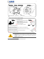
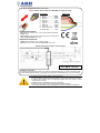
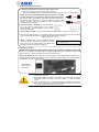
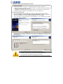
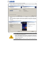
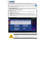
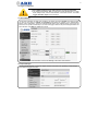
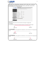
1 ParkIT ANPR Camera with LetUgo Parking Management Software Quick Start Guide ! READ BEFORE USE ! Contact Information Should you have any problem during operating the ParkIT cameras, please contact: Contact data and technical support process of local PARKIT LetUgo distributor: Manufacturer ARH Inc. Királyhágó tér 8-9. H-1126 Budapest, Hungary Phone: +36 1 2019650 Web: www.arhungary.hu 2 1. Open the package Unpack the camera on smooth ground to avoid scratching the hardware. 2. Check package contents All-in-One ParkIT camera pre-assembled with Ethernet and Power/Trigger/Serial cable and installed wall mountable bracket in an IP65 class weatherproof housing: Ultra-low lux B&W camera equipped with IR pass filter Motorized zoom, focus and iris Built-in infrared illuminator unit with four high power SMD LEDs synchronized with the camera, adjustable illumination intensity Printed quick start guide LetUgo Install DVD FXMC USB key 3. Take the camera out of the package Grab the camera by its body and lift it out of the package. The camera is wrapped in protecting bubble wraps. The camera is pre-assembled with its bracket, sunshield and two cables. The camera emits invisible, high power infrared light. Do not look into the light directly to avoid the risk of eye damage! 1. ● Make sure that the package is lying on a flat and solid surface. ● Open the package only in dry environment, within the storing temperature range of the camera: -35 ºC to +55 ºC (-31 ºF to 130 ºF). ● Do not store the camera disconnected from power for longer periods to protect its internal battery feeding the camera RTC (Real Time Clock). This battery can keep the RTC settings for approx. one year and cannot be recharged but replaced by the manufacturer only. 2. ● Never use the camera without its sunshield. ● Avoid scratching the camera front during unpacking. 3. ● Read the ParkIT Install Guide for details of installation. 3 4. Hardware Overview Camera optics * Sunshield Green status LED Infrared LEDs (x4) Light sensor Screws (x4) Red status LED Foot 5. Adjust the camera bracket and install the hardware 5.1 Adjusting the cover Ball joint 1. Loosen both screws fastening the ball joint. (Use size 4 Allen key). 2. Adjust the cover into the desired position (35-degree spatial angle in any direction). 3. Fasten the screws back. NOTE: Do not overtighten the screws. Cover Foot 5.2 Adjusting (rotating) the foot If greater rotation is needed than 35º then rotate the foot for additional 20º (see figure) to rotate the cover by: 1. Remove the four screws located at the back of the foot. (Use size 4 Allen key). 2. Rotate the foot by 180 degrees. 3. Place the screws back into the holes and screw them back on. NOTE: Do not overtighten the screws. 5. ● Read the ParkIT Install Guide for details of installation. ● Use appropriate screws according to the mounting surface to secure the camera. ● Consider the weight of the camera (4.85 lbs (2.2 kgs)) when choosing screw lengths. ● Do not overtighten the screws. * Technical specifications are subject to change without prior notice. 4 6. Connect the Cables 6.1 Power/Trigger/Serial Cable Connection NOTE: Seal the unused cable cores BEFORE connecting to power. Description 1. 2. 3. 4. 5. 6. 7. 8. 9. 10. Cable color DC in - .....................Black DC in + ..................... Red Opto in + ................. Brown Opto out -.................. Red Opto out + .................Grey Opto in - ................. Orange Serial TX .................. White Serial RX................. Green NC (no connect)...... Yellow Serial GND................ Blue POWER SPECIFICATIONS DC input: 12V nominal (12V…15V), reverse polarity protected Power: 10W Input current: 1.0A (transient current max 2.5A for a few μsecs) Over-current protection: by fuse TRIGGER SPECIFICATIONS Output: Open Collector (max. 12V DC/ 10mA) Input: Min. 5V DC, max 12V DC, Pulse width: min 10 ms Sample application for trigger input and output ! DC input: 12-15V ! 6.2 Ethernet Connection The camera is equipped with a CAT5 UTP crossover cable with RJ45 plug. It can be connected to both PCs and network switches directly. The length of the cable can be extended with e.g. an inline coupler. 6. ● Failures due to improper cabling voids the warranty. ● Avoid accidental contacting of the end sleeves. It may cause permanent damages. ● Camera cable endings are not waterproof! Protect them from water to avoid damaging the camera! ● Please consider voltage drop if you use long cables! ● The serial port of the camera complies with the RS232 standard. ● Use proper cables with proper cable glands to keep the camera unit waterproof. 5 7. Access and Configure the Camera 7.1 Software Requirements for the ParkIT camera with LetUgo Windows operating system with administrator privileges Web browser: Mozilla Firefox 4, Internet Explorer 8, Google Chrome 14.X.X.X or later editions 7.2 Steps of accessing the web interface of the camera from a browser: 1. Connect the camera to a computer or network switch then power on the camera. After it is powered on, both status LEDs (red and green on the camera front) are turned on while the camera is booting. After finished, the green status LED flashes two times signaling that the camera is ready for operation. 2. Set your computer’s IP address (or enter an alternate IP) in the 192.0.2.x subnet where x is an integer number between 1 and 254 except 3– and your subnet mask to 255.255.255.0. 3. Use the ping command to test the communication with the camera: C:\>ping -t 192.0.2.3 4. Soon, the ping package returns. If not, power off then on and enter the previous ping command again. After 3 seconds, the camera will try to get IP address automatically via DHCP: Reply from 192.0.2.3 5. Start a browser then enter the default IP address (192.0.2.3) of the camera into the address bar and hit enter. After this, the camera starts with administrator privileges, ready to be set up and configured. 8. Configure the Camera The ParkIT camera must be configured before Installing LetUgo. With the Configuration Wizard, the camera can be optimized for license plate recognition quickly and easily. Of course, the use of the wizard is optional – camera properties can be set up manually as well. Steps of the Wizard: Network setup, time and date settings, camera task selection, configuration of image properties, autozoom and autofocus, event managing and profile settings. For more information on the Wizard, see ParkIT User’s Manual. Web interface after configuring the camera: 7-8. ● To enable all camera functions, enable (and update) JavaScript and ActiveX controls in your browser. ● Changing the default IP address of the camera is recommended– especially if more ARH cameras are used in the same network – to avoid IP address conflict. ● To alter the IP address of your computer, administrator privileges are necessary. ● Power on the camera only if the ambient temperature of the camera reaches the camera’s startup temperature of -20ºC (-4ºF). 6 9. Installing the LetUgo Parking Management Software 9.1 System requirements Pentium 4 2GHz CPU or equivalent, 1GB RAM (2GB recommended for Windows7) Windows XP SP3 or Windows 7 Operating System, HD Ready resolution (1366x768) with minimum 64 MB dedicated video memory. 100 Mbit/sec or better LAN connection, Ethernet switch for more cameras, 1 USB port (v2.0) 30GB HDD (approx. 30Mbytes for the application, the rest is for images, etc.) 9.2 Steps of installing LetUgo 1. The setup program starts automatically after inserting the disc (DVD) into the optical drive. 2. After clicking [Next], read the END-USER LICENSE AGREEMENT. Accept the agreement to continue the installation by selecting I accept the agreement and clicking [Next]. 3. In the next step, the setup searches for .NET framework on your computer and installs it automatically if it is not available. 4. After this, enter the license key located on the side of the LetUgo DVD box. After entering the key, click [Next] to view necessary components to be installed. Click [Next] again to begin to install these components. ● If the setup program does not start automatically then run INSTALL\LetUgo_Setup.exe located on the provided Install DVD. ● To install LetUgo, administrator privileges are necessary. ● The license key is valid only with the USB dongle purchased for the software! 7 5. Select the destination folder for LetUgo then click [Next]. 6. Create a desktop icon for LetUgo and/or launch it automatically at Windows startup right after installation by ticking the corresponding checkboxes. 7. Check the destination folder before installation then click [Install] to start copying LetUgo to your computer. 8. When the installation is complete, read the LetUgo User Manual (View LetUgo User’s Manual (pdf) and/or launch the application right after the installation by checking the corresponding checkboxes. 9. Click [Finish] button to finish the installation. ● The installer places files into the Windows/System32 directory as well. Check your privileges before installing LetUgo. ● However, the application needs only approx. 30 Mbytes of free disk place, at least 30 GBytes available free disk space is recommended for saved images, events etc. The required free disk space highly depends on the size and the amount of the saved images. ● Read the Troubleshooting Guide for details of network setup (firewall, IP addresses, proxy etc.). 8 10. Starting the LetUgo 1. Connect the USB dongle into a free USB port and wait until the driver is installed. 2. Open the application from the start menu or by clicking on the LetUgo desktop icon (if created). 3. Enter the ‘admin’ Login and ‘admin’ Password to begin to use the program. At first time, the LetUgo starts with administrator privileges. 11. Adding the ParkIT camera 1. Click Settings menu then select the Cameras tab. 2. Click [New] and enter the data of the new camera: NAME: any unique text DIRECTION: Direction of the observed lane(s). Note, that in case of ‘undefined’ direction, time spent in cannot be calculated. ADDRESS: IP address of the camera PORT: Port of the computer –running LetUgo– assigned for communication with the camera. TIME OF OPENING: It refers to the period of time during which the barrier is in opened position. CHECK: The camera can take into account/ignore Permissions and/or Blacklist. Check the one(s) to be taken into account. 3. Click [OK] to apply changes. ● Without connected USB dongle, LetUgo starts with limited (management) functions. ● Filling the name and the address field is mandatory. Filling the other fields is optional. ● For more information on using LetUgo, refer to LetUgo User’s Manual. 9 12. Trigger Configuration ● Using GPIO (hardware) trigger with LetUgo is strongly recommended. ● The LetUgo automatically sets up trigger and upload configurations. To alter these settings easily, use the Web interface of the ParkIT camera. The main trigger calibration steps are the followings: 12.1 Event Manager Use the Event Manager to select (and combine) your trigger source(s). Register the trigger sources you want to use, select an Output and Configure their settings by clicking on the corresponding buttons. After configuration, enter the assigned capital letter of the selected trigger source into the formula box or express a relationship if you use more triggers with the help of the assigned letters and logic operators. Click Start to validate the formula. For more information on the Event Manager, see ParkIT User’s Manual. 12.2 Upload Manager Use the Upload Manager to select the target, filename and protocol for uploading camera images, event data and trigger information. 10 12.3 GPIO Trigger When triggering the camera through its GPIO port, the GPIO Trigger can be configured in the following menu. Note that Start offset and End offset values must be specified to the camera site. Recommended: 500ms difference between the two values (e.g. Start offset: 0, End offset: 500). For more information read Troubleshooting Guide. Trigger mode: Trigger task (upload) can be set to be launched at various stages of a trigger signal: 1. Level Mode In case of level mode, trigger task is executed continuously until the end of the trigger signal: 1 0 Trigger Start Trigger End 2. Rising Edge Mode In case of rising edge mode, trigger task is executed once, at the moment when the trigger signal arrives: 1 0 Trigger Start Trigger End 3. Falling Edge Mode In case of falling edge mode, trigger task is executed once, at the moment when the trigger signal ceases: 1 0 Trigger Start Trigger End


![Computo metrico estimativo [file]](http://vs1.manualzilla.com/store/data/006110712_1-36dbecbceaf605fa2e5d4a32099470bb-150x150.png)