1
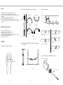
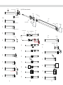
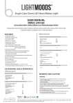
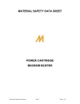
FEATURES OF Neon-Flex - 3 series SMD
IP 65 Accessories Kit
1. Model: DC24V-60 - 3 - Dome
2. Rated input voltage: DC 24V
Both
Connection
IP
65 Ends
Accessories
KitApplication Accessories Kit
3. Rated Power:12W/m
4. Dimension: 11.5*29mm
01 Front Connector
02 Front Connector
Cover
Anti-skidding clip
HST
Remark: HST--Heat Shrink Tube
5. LED quantity: 60LEDs/mtr
6. LED Spacing:16.67mm
USER MANUAL
7. Min. cutting length:100mm( 6LEDs)
8. Max. running length: 10mtrs for single end feed;
20mtrs for double ends feed
9. Light color: RGB
Neon-Flex - 3 series SMD
1 pc
1 pc
2 pcs
4 pcs
2 pcs
Both Ends Connection Auxiliary Accessories Kit
Glue
1 pc
Use LED Controller to realize color changes.
10. Min. bent diameter: 120mm
Single End Connection Application Accessories Kit
Do not twist the light .
Front Connector Accessories Kit
11.Protection rate: IP68/IP65
12.Protection rate for IP68: Protected against dust and submersion in
water (1meter above).
NOTE: All connector joints must be connected correctly to achieve
01 (or 02) Front Connector
Cover
Anti-skidding clip
HST
Remark: HST--Heat Shrink Tube
IP68 rating.
End Cap Accessories Kit
13.Can be cut and extended
End Cap
Shading Sheat
HST
Remark: HST--Heat Shrink Tube
14.Long lifetime: 5 years
15.Working ambient temperature: -20℃~45℃
1 pc
1 pc
2 pcs
1 pc
1pc
1pc
1pc
16.Operating(bending) ambient temperature: 0℃~45℃
Single End Connection Auxiliary Accessories Kit
PLEASE READ THESE INSTRUCTIONS CAREFULLY
ACCESSORIES(SALE SEPARATELY)
BEFORE INSTALLATION LEAVE A COPY FOR THE
IP 68 Accessories Kit
END USER/MAINTENANCE ENGINEER FOR FUTURE
Both Ends Connection Application Accessories Kit
REFERENCE
01 Front Connector
02 Front Connector
Rubber Gasket
Aluminum Mounting Piece
Anti-skidding clip
Screws
1 pc
1 pc
2 pcs
2 pcs
2 pcs
8 pcs
Single End Connection Application Accessories Kit
Front Connector Accessories Kit
01 (or 02) Front Connector
Rubber Gasket
Aluminum Mounting Piece
Anti-skidding Clip
Screws
1 pc
1 pc
1 pc
1 pc
4 pcs
End Cap Accessories Kit
1pc
1pc
1pc
1pc
4pcs
The Tail Plug
Aluminum Mounting Piece
Anti-skidding Clip
Rubber Gasket
Screws
Version No.:V1.1
1
Glue
1 pc
WARNING AND CAUTION
WARNING
1.Before making any cuts, installation, maintenance or connection,be sure
the mains is disconnected!
2.NOTE: ALL CONNECTOR JOINTS MUST BE CONNECTED CORRECTLY TO
ACHIEVE IP68 RATING.
3.Please operate this flex light by instructions, and confirm the work voltage,
it must be matched with product requirements
4.Please confirm the polarity of connector before insertion front connection cable.
5.Connect and cut this product correctly. Any wrong operation will damage this
product.
6.No pressing on this product during storage, long term pressing may lead to
damage.
7.Using qualified DC power supply.
8.Min. bending diameter 120mm, see Fig. 1.
9.Do not twist the light as Fig. 2 and Fig. 3.
10.Do not hang this flex light in sky as Fig.4.
11.Cutting at wrong location will result in a failure of light! See Fig.5.
2
CAUTION
Twist the light is forbidden and correct bending way
Light Surface
Light Surface
Light Surface
PCB
Light Surface
LED
PVC
×
1. Suitable for mounting on normally flammable surfaces. .
2.Use only factory-recommended connectors and accessories.
3.To ensure its long life span, operate the light properly in accordance with the
instructions.
4.Do not operate in more than 45℃ ambient temperature.
5.Assemble the Connector correctly as Fig.6.
6.Max. running length depends on the energizing way as Fig.7 shown.
7.Do not operate light when ambient temperature is below 0℃ that may injury
the light .
Fig . 5 Unit cutting guide
×
×
100mm
Cutting line
Light Surface
Light Surface
ASSEMBLY AND INSTALLATION
1. Turn off the electricity before operation.
2. Cutting the light at correct location ( if need).
3. Assemble light according to Fig. 8,Fig. 9 .
4. Install U channel and light according to Fig.10.
5. Wiring all connectors to the power line and checking whole circuit wiring.
Cable color coding basics Refer to Fig. 11.
6. Applying controller to Fig.12.
Recommened Use
√
√
Fig . 2
Beginning cutting
Wave cutting is incorrect
×
R>90°is incorrect
×
R<90°is incorrect
×
Fig . 3
√
FIGURES
Fig . 4 Hang suspended installation as the picture illustrated is
forbidden
The correct cutting way,R=90°
Fig . 1 Minimum bent diameter 120mm
Fig . 6 Correct insert position of connector pins
×
120mm
Light Surface
×
For 01 Type Front Connector
Light Surface
PCB
①
②
01 Front Connector
01
Pins
3
4
5
Aluminum Mounting Piece
Fig . 7 Energizing Way
Connector Pins
Connector Pins
Light
Front connector
Screw
Rubber Gasket
① Single ends connection for Max. length 10m
Anti-skidding Clip
Step
×
√
1.
Anti-skidding Clip
② Both ends connection for Max. length 20m
2.
02
Aluminum Mounting Piece
For 02 Type Front Connector
01 Front Connector
3.
02Front Connector
Light Surface
Fig . 8 IP68 Connector Assemble
4.
Diagram
02 Front Connector
Front connector
PCB
Pins
Rubb
02
A
um
lu m in
Mou
n ti n g
P ie c
e
S c re
er Ga
sket
w
F ro n
t con
n e c to
5.
r
Front connector
6.
A n ti -s
L
k id d in
g C li
p
ig h t
7.
Connector Pins
Connector Pins
Rub
Th
i
e ta
l pl
ber
Gas
ket
Screw
ug
A n ti -s
k id d
in g C
8.
li p
Caution: Right Steps of Screwing:
×
√
6
Alu mi nu m Mo
un tin g Pie ce
9.
Scr ew
7
8
Rubber Gasket
Light
The tail plug
Aluminum Mounting Piece
Fig . 9 IP65 Connector Assemble
Screw
Cove
r
A n t i-
Rubber Gasket
s k id
Anti-skidding Clip
Step
d in g
C li p
L ig h t
1.
HST
Front Connector
Anti-skidding Clip
S h a d in
g shee
t
End C
ap
HST
2.
Aluminum Mounting Piece
Front Connector
Cover
Anti-skidding Clip
Light
3.
Light
Rubber Gasket
End Cap
Step
1.
4.
Pay attention to
wide open side
Shading Sheet
End Cap
Step
2.
1.
5.
G lu
3.
2.
6.
G lu e
4.
The tail plug
G lu e
3.
5.
7.
Screw
4.
6.
8.
Heat
Heat
Caution: Right Steps of Screwing:
9.
9
7.
5.
8.
6.
10
11
e
Fig . 10 Installation Guide
GUARANTEE
Fig . 11 Cable color coding basics
For Self-lock Aluminum U-channel
1. We provide lifelong technical assistance with this product:
A 3 year warranty is given from the date of original purchase.
The warranty is for free repair or replacement and covers manufacturing
faults only.
For faults beyond the 3 year warranty we reserve the right to charge for
time and parts.
Advances technology for the will be selected firstly.
2. Warranty excludes below:
Any man-made damages caused from improper operation, assembly,
wiring, connection, installation, transport and storage.
Improper input voltage, current, operating and working environment.
The product appears to have excessive physical damage.
Damage due to natural disasters and force majeure.
Product label or data code have been damaged.
3. Repair or replacement as provided under this warranty is the exclusive
remedy to the customer.
We shall not be liable for any incidental or consequential damages for
breach of any stipulation in this warranty.
4. Any amendment or adjustment to this warranty must be approved in
writing by us only.
5. This manual only applies to this model. We reserves the right to modify
the manual and keep the right to make final explanation of this manual.
or "+”
Aluminum U-channel
Clip
Fig . 12 Wiring Diagram
POWER
LED CONTROLLER
DC-
light
a
G
R
DC
- +
+-
Aluminium U-channel
+
B
DC+
AC
L N
G RB V
Installation Surface
Screw
b
c
For Common Aluminum U-channel
Light Surface
Aluminium U-channel
Installation Surface
Screw
12
13
14