1
Multi-Channel
LCD Rack Monitor
PRM Series
User's Manual
PRM-902A
PRM-902Q
PRM-702A
PRM-702Q
13."2"2
Contents
Warnings .......................................................................................................... 3
Features ............................................................................................................ 4
Name & Function of Each Part ......................................................................... 5
OSD Menu Organization & Adjustment ........................................................... 8
Other Functions .............................................................................................. 15
System Default Value...................................................................................... 24
Specifications ................................................................................................. 25
Contents
2
MULTI-CHANNEL LCD RACK MONITORS
Warning
· Always use DC 12V power.
· If liquid comes in contact with this product, please disconnect the product immediately
and seek professional support before continued use.
· Keep unit disconnected during extended periods of nonuse.
· Keep unit well-ventilated to prevent overheating.
· Do not install the product near any heat-generating equipment. Also, keep the product
out of direct sunlight or dusty areas.
· Clean the product with a noncommercial, mild detergents only.
Warning
· When transporting the product, make use of its original packaging for safer carriage.
FCC (Federal Communications Commission)
This equipment has been tested and found to comply with the limits for class A digital device, pursuant to
part 15 of the FCC Rules. These limits are designed to provide reasonable protection against harmful
interference when the equipment is operated in a commercial environment. This equipment generates,
uses, and can radiate radio frequency energy, and if not installed and used in accordance with the
instruction manual, may cause harmful interference to radio communications. Operation of this equipment
in a residential area is likely to cause harmful interference in which case the user will be required to correct
the interference at his own expense.
! Warning!! : Changes or modifications not expressly approved by the manufacturer could void the
user’s authority to operate the equipment.
Disposal of Old Electrical & Electronic Equipment
(Applicable in the European Union and other European countries
with separate collection systems)
This symbol on the product or on its packing indicates that this product shall not be treated as household
waste. Instead it shall be handed over to the applicable collection point for the recycling of electrical and
electronic equipment. By ensuring this product is disposed of correctly, you will help prevent potential
negative consequence for the environment and human health, which could otherwise be caused by
inappropriate waste handling of this product. The recycling of materials will help to conserve natural
resources.
3
13."2"2
Features
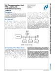
PRM Series LCD Rack Monitors have the following features:
4
Features
· Compatible with varied SDI Signals
The product is compatible with varied SDI signal
- 480i, 576i, 720p, 1035i, 1080i, 1080p, 1080psf, 2K
· Compatible with varied Analog Signals
The product is compatible with varied Composite, S-Video signal
- NTSC, PAL, SECAM
The product is compatible with varied Component, RGB signal
- 480i,576i,480p,576p,720p,1080i,1080p
· Waveform/Vector Scope/Audio Level Meter
“Y”, “Cb”, “Cr” Waveform & Vector Scope available for SDI Signals
16-CH Embedded Audio Level Meter
· Audio Out
Built in Audio De-embedder and Internal Speakers
Stereo Audio out using phone jack
· Knob Control
Easy to adjust user configuration using the control knob
· BLUE & MONO
· H/V Delay
· Wide Variety of Markers & Safety Areas
Center Marker, Safety Area Marker, Aspect Marker, Display Size(Scan)
· Pixel To Pixel
Provides both full screen and unscaled native image.
· Wide Screen / LED Backlight (902Q/702A/702Q), CCFT Backlight (902A)
· 24Bit RGB LVDS Interface Panel
· DC Compatible
The product is powered by normal 12V source.
· Remote Control Function
Simple remote controllability with single cable connection,
no additional modules required
· Additional Features
Active Loop Through/SDI,
902A - 600:1 contrast ratio, 600 cd/mY brightness
902Q - 1000:1 contrast ratio, 400 cd/mY brightness
702A - 700:1 contrast ratio, 350 cd/mY brightness
702Q - 800:1 contrast ratio, 400 cd/mY brightness
OSD user interface, Rack Mountable
MULTI-CHANNEL LCD RACK MONITORS
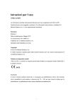
Name & Function of Each Part
<FRONT>
slk
PRM-902A
PRM-902Q
wv~ly
zkpTh
hUGsl}lsGtl{ly
zkpTi
o}Gklsh
Name & Function of Each Part
huhsvn
iypno{ulzz
jvu{yhz{
joyvth
}vs|tl
PRM-702A
PRM-702Q
{hss
{hss
hzwlj{
~h}lmvyt
|w
is|lGMG tvuv
kv~u
thyrly
tlu|
zjhu
lu{ly
jvu{yhz{
}vs|tl
iypno{ulzz
joyvth
zkpTh
huhsvn
thyrly
o}Gklsh
h|kpvGsl}lsGtl{ly
|w
tlu|
zkpTi
zjhu
hzwlj{
is|lGMG tvuv
~h}lmvyt
kv~u
lu{ly
· [BRIGHT] knob
Used to adjust the degree of brightness between MAX(25) and MIN(-25).
· [CONTRAST] knob
Used to adjust the contrast ration between MAX(25) and MIN(-25).
· [CHROMA] knob
Used to adjust the saturation between MAX(25) and MIN(-25).
· [VOLUME] knob
Used to adjust the volume between MAX(20) and MIN(0).
· [SDI-A] button
Used to select SDI A Input.
· [SDI-B] button
Used to select SDI B Input.
· [ANALOG] button
Used to select desired Analog Input (CVBS1/2/3, S-Video, Component, RGB).
5
slk
wv~ly
13."2"2
· [SCAN] button
Used to transfer from OVER SCAN mode to ZERO SCAN mode.
Mode changes in the order of ZERO SCAN -> OVER SCAN -> PIXEL TO PIXEL
-> ZERO SCAN.
-This function is not available in Internal Pattern and Wave Form/Vector Scope full size.
· [ASPECT] button
Used to toggle aspect ratio in SD from standard to anamorphic.
- This function is not available in Internal Pattern and Wave Form/Vector Scope full size.
· [MARKER] button
Used to show MARKER on the screen. The type of marker at work may be selected
on the main menu.
- This function is not available in Internal Pattern, Wave Form/Vector Scope full size,
Pixel to Pixel and HV Delay mode.
· [BLUE/MONO] button
You may remove R(red) and G(green) from the input signal and play the screen only with
B(blue) signal. Button may be pressed twice to change the screen to MONO mode.
(This mode uses only Luminance value)
- This function is not available in Internal Pattern and Wave Form/Vector Scope full size.
· [AUDIO LEVEL] button
Used to active AUDIO LEVEL METER on the screen. The type of audio level meter
at work may be selected on the main menu.
- This is available only in SDI input mode.
· [WAVE/VECTOR] button
Used to activate the Waveform or Vector Scope.
Small and Full Waveform/Vector Scope display can be selected in the system menu.
Small display : YCbCr ˧ Y ˧ Cb ˧ Cr ˧ Vector ˧ off
Full display
: Y ˧ Cb ˧ Cr ˧ Vector ˧ off
(Use “WAVE/VECTOR” button to control)
- This is available only in SDI input mode.
· [UP] button
Used to navigate menu during OSD menu activation. It may also be used to toggle
clockwise through 1:1 quadrants in native scan mode.
· [DOWN] button
Used to navigate menu during OSD menu activation. It may also be used to toggle
counterclockwise through 1:1 quadrants in native scan mode.
· [MENU] button
Used to activate the OSD menu.
· [ENTER] button
Used to confirm a chosen value (or mode) within the OSD menu.
- This can be used to control the position of Wave/Vector in small size.
· [POWER] button
Power On/Off button.
If the signal is normal, LED lights in Green. If the signal is unsupported or disconnected,
LED flashes in Yellow.
· TALLY
LED indicating monitor’s current status using optional Remote.
]
Name & Function of Each Part
· [HVDELAY] button
Used to activate the HV Delay mode.
- This function is not available in Internal Pattern and Wave Form/Vector Scope full size.
MULTI-CHANNEL LCD RACK MONITORS
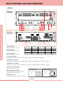
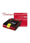
<REAR>
kjGpu
h|kpvG v|{
Name & Function of Each Part
PRM-902A
PRM-902Q
zkpGv|{w|{
j}izXViVw
zkpGiGpuw|{
j}izYVnVVzT
zkpGhGpuw|{
j}izZVyVwVzTj
AUDIO OUT
yltv{l
mhj{vyG wnt
FACTORY PGM
PRM-702A
PRM-702Q
REMOTE
· SDI A-IN (BNC)
SDI A signal input terminal
SDI OUTPUT
CVBS1/B/Pb
SDI B INPUT
CVBS2/G/Y/S-Y
SDI A INPUT
CVBS3/R/Pr/S-C
DC IN
j
j
j
yni
zT}
· SDI B-IN (BNC)
SDI B signal input terminal
X
j}izX
w
i
uGjU
Y
j}izY
n
· SDI-OUT (BNC)
SDI signal output terminal
Z
j}izZ
w
y
j
· CVBS1/B/Pb (BNC)
Signal input terminal used for COMPOSITE1, RGB B, COMPONENT Pb signals.
· CVBS2/G/Y/S-Y (BNC)
Signal input terminal used for COMPOSITE2, RGB G, COMPONENT Y, SVIDEO Y signals.
· CVBS3/R/Pr/S-C (BNC)
Signal input terminal used for COMPOSITE3, RGB R, COMPONENT Pr, SVIDEO C signals.
· AUDIO OUT (phone jack)
Used to audio output jack.
· FACTORY PGM (15 pins)
Input connector for FACTORY PGM
allowing for firmware update.
· REMOTE (RJ-45)
Connection for remote control of monitor.
PRM-902A/902Q
PRM-702A/702Q
kj GpuG
XaGnu k
[aGRXY}
7
kjGpuG
[
X
Z
YGaGRXY}
Y
ZGaGnuk
Y
X
Z
13."2"2
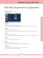
OSD Menu Organization & Adjustment
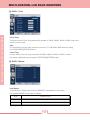
[1] MAIN - Picture
· Contrast
This item controls the contrast ratio.
-Contrast can be adjusted by using the [CONTRAST] control knob on the front of the monitor.
· Chroma
This item controls saturation.
-Saturation can be adjusted by using the [CHROMA] control knob on the front of the monitor.
· Aperture
This item controls the picture sharpness.
· Phase
This item controls Phase value (Hue).
-This function is only available in Composite and S-Video NTSC Input.
· NTSC Setup
This item sets IRE value in NTSC mode between 0 IRE and 7.5 IRE.
-This function is only available in NTSC Input.
8
OSD Menu Organization & Adjustment
· Brightness
This Item controls the degree of brightness.
-Brightness can be adjusted by using the [BRIGHT] control knob on the front of the monitor.
MULTI-CHANNEL LCD RACK MONITORS
OSD Menu Organization & Adjustment
[2] MAIN - Color
· Color Temp
This item controls Color Temperature with presets of 3200K, 5600K, 6500K, 9300K, and User1,
User2 & User3 mode.
· User
On User Mode, the user may select and control R, G, & B GAIN, BIAS values by using
the [UP]/[DOWN]/[ENTER] buttons.
· Color Copy
In User mode, user can copy the preset of 3200K, 5600K, 6500K or 9300K to make
the custom adjustment by using the [UP]/[DOWN]/[ENTER] button.
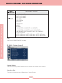
[3] MAIN - Marker
· Line Marker
This selects the marker type when the MARKER is displayed on the screen.
Compatible MARKER types are as follows:
tvkl
thyrlyGjshzz
okGVGzkGX]a`
X]a`SG [aZSG [aZG vuGhpySG X\a`SG X[a`SG XZa`SG XU_\aXSG YUZ\aXSG XU_\aXG MG [aZ
zkG[aZ
X]a`
9
13."2"2
· Center Marker
This item displays the CENTER MARKER on the screen.
· Safety Area
This item controls the size of the SAFETY AREA between 80%, 85%, 88%, 90%, 93%,
and 100%.
· Marker Color
This item controls Marker color. Selectable colors are white, gray, black, red, green, and blue.
-Line Marker, Center Marker and Safety Area functions are operates only
after activated by pressing the MARKER button on the front of the monitor.
[4] MAIN - Remote
yltv{lGOyqT[\P
XaGw X
YaGw Y
ZaGw Z
[aGw [
\aGw \
]aGw ]
^aGw ^
_aGnu k
X
_
· Pin1 ~ Pin6
The user may connect RJ-45 jack to the remote terminal on the rear of the unit and designate
a function for each pin.
The selectable functions are as follows:
10
OSD Menu Organization & Adjustment
· Marker Mat
This item darkens the area outside of MARKER setting area. The degree of the matte
is between OFF(0) and (7).
The higher the number the darker MARKER the matte becomes.
MULTI-CHANNEL LCD RACK MONITORS
OSD Menu Organization & Adjustment
zG}
ANALOG CHANNEL
DIGITAL A CHANNEL
DIGITAL B CHANNEL
TALLY RED
TALLY GREEN
BLUE ONLY
UNDERSCAN
ASPECT
HVDELAY
16:9 MARKER, 15:9 MARKER, 14:9 MARKER,
13:9 MARKER, 4:3 MARKER, 4:3 ON AIR MARKER,
1.85:1 MARKER, 2.35:1 MARKER, 1.85:1 & 4:3 MARKER
CENTER MARKER
SAFETY AREA 80%, SAFETY AREA 85%, SAFETY AREA 88%,
SAFETY AREA 90%, SAFETY AREA 93%, SAFETY AREA 100%
· Pin7
PIN7 is for POWER ON/OFF use only.
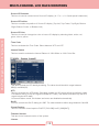
[5] MAIN - System [page1]
· System Default
User can use the System Default menu to initialize the values of the monitor.
· Waveform Size
This item controls the size of Waveform or Vector Scope.
11
13."2"2
· Waveform Position
This item controls the position of Waveform or Vector Scope between Right, Center and Left.
-In normal display, press Enter button to activate this feature in activated Waveform .
-This feature can be activated in small size mode only.
· Waveform Blending
This item activates the blending of Waveform or Vector Scope.
-This feather activates automatically if Waveform overlaps with OSD.
-This feather can be activated in small size mode only.
· Audio Channel
This item sets embedded audio channel selects CH1 ~ CH16, and Off.
-Waveform Size, Waveform Position and Waveform Blending functions are operates
only after activated by pressing the WAVE/VECTOR button on the front of the monitor.
-Menus or features which are related with Waveform and Audio enables can be enabled in
SDI input mode only.
[6] MAIN - System [page2]
· Source ID
This item is used to activate the source ID display by selecting BG Type or Char Type.
12
OSD Menu Organization & Adjustment
· Audio Level Meter
This item controls the position of audiolevel meter between Horizontal and Vertical.
MULTI-CHANNEL LCD RACK MONITORS
· Source ID Character
This item is used to customize the Source ID display. (A~Z, a~z, 0~9 and special characters)
· Source ID Position
This item controls the position of Source ID display. (Top-Left, Top-Center, Top-Right, Bottom
-Right, Bottom-Center, or Botttom-Left)
OSD Menu Organization & Adjustment
· Source ID Color
This item is used to change the color of source ID display by selecting black, white, red,
green, blue or yellow.
· Time Code
This item activates the Time Code. Select between VITC and LTC.
· Internal Pattern
This item used to activate the Internal Pattern of 100% White or 100% Color Bar.
[7] MAIN - System [page3]
· Back Light
This item controls the LED backlight setting. The value should be within range between
MIN(0) and MAX(50).
· AFD
This item activates the AFD mode. Selectable modes are Off, Aspect Mode and Marker mode.
-This feature action in only SDI signal included AFD Data. (This feature activates only with SDI
signal includes AFD data.)
-In Internal Pattern mode, this feature and menu are disabled automatically.
· Set ID
This item controls the Set ID setting for UMD. The value should be within range between 0 and 99.
· Closed Caption
This item controls closed caption ON/OFF.(708, 608[Line21], 608[ANC])
· Firmware Version
This item is the firmware version of the system.
· License
13
13."2"2
[8] zkpGhGpuw|{Gt
·Gw ytT `WYhGVG`WYxGVG^WYhGVG^WYxGGGGG
GGGGzkpGhGpGU
· w GzkpThGGGGGGGGGG
GGGzkpGhGUGvzkGG GGGGGU
TpGGG GGGGGG
GGGSGGGGGG GGG
GGGGGU
TpG G GGGG GGvzk
GGGU
[9] zkpGiGpuw|{Gt
·Gw ytT `WYhGVG`WYxGVG^WYhGVG^WYxGGGG
GGGGGzkpGiGpGU
· w GzkpTiGGGGGGGGGG
GGGzkpGiGUGvzkGG GGGGGU
TpG GG GGGGGG
GGGSGGGGGG GGG
GGGGGU
TpG G GGGG GGvzk
GGGU
[10] huhsvnGpuw|{Gt
· wytT`WYhGVG`WYxGVG^WYhGVG^WYxGGGGG
GGGhuhsvnGpGU
· w GhuhsvnGGGGGGGGG
GGGGvzkGGGGGGU
zGGG GG GGG|wVkv~uG
GGGGGGlu{lyGGGU
TpGGG GGGGGG
GGGSGGGGGG GGG
GGGGGU
TpG G GGGG GGvzkG
GGGU
MULTI-CHANNEL LCD RACK MONITORS
Other Functions
[1] PIXEL TO PIXEL
· PRM-Rack monitor’s Pixel to Pixel mode displays input signal without scaling.
· To activate the [Pixel to Pixel] mode, access the Scan menu in Syetem menu and select
[Pixel to Pixel].
Other Functions
· In the [Pixel To Pixel] mode, use the [UP]/[DOWN] buttons to toggle between 1:1 scan
sections
Input
HD 1080i/1080p
Action Button
Available Modes
[UP]
Center -> Left Top ->Mid Top -> Right Top -> Right Mid -> Right
(Clockwise)
Bottom -> Mid Bottom -> Left Bottom -> Left Mid -> Center -> ….
[DOWN]
Center -> Left Mid -> Left Bottom -> Mid Bottom -> Right Bottom
(Opposite)
-> Right Mid -> Right Top -> Mid Top -> Left Top -> Center -> …
- OSD change
[UP]
[UP]
[DOWN]
[DOWN]
[UP]
[DOWN]
[UP]
[DOWN]
[UP]
[DOWN]
[UP]
[DOWN]
[UP]
[DOWN]
[UP]
[UP]
[DOWN]
[DOWN]
15
13."2"2
Input
HD 720p
Action Button
Available Modes
[UP]
Center -> Left Top -> Right Top -> Right Bottom -> left Bottom ->
(Clockwise)
[DOWN]
(Opposite)
Center -> …
Center -> Left Bottom -> Right Bottom -> Right Top -> Left Top
-> Center -> ….
- OSD change
[DOWN]
[UP]
[DOWN]
[DOWN]
[UP]
[UP]
[DOWN]
[DOWN]
- Pixel To Pixel mode is available in SD mode, but 1:1 sections cannot be rotated through
as with HD sources.
16
Other Functions
[UP]
[UP]
MULTI-CHANNEL LCD RACK MONITORS
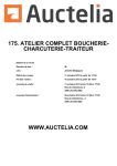
· Positions in HD Signal 1080i/1080p mode
[UP]
Left Top
Mid
Top
[UP]
Center
[DOWN]
[DOWN]
Right
Top
Other Functions
[UP]
[UP]
Right
Mid
[UP]
[DOWN]
[DOWN]
[DOWN]
[UP]
[UP]
[UP]
[DOWN]
Mid
Bottom
[DOWN]
Left
Bottom
Right
Bottom
Left
Mid
[DOWN]
· Positions in HD Signal 720p mode
[UP]
Center
Left Top
[DOWN]
[DOWN]
[UP]
[DOWN]
[UP]
[UP]
Right Bottom
[DOWN]
17
Left Bottom
Right Top
13."2"2
[2] Waveform
Small display : YCbCr ˧ Y ˧ Cb ˧ Cr ˧ Vector ˧ off
Full display : Y ˧ Cb ˧ Cr ˧ Vector ˧ off
· Waveform
OFF
Waveform
· Waveform Size
Small (Cb, Cr, Y)
Full (Y)
If push the Input button (SDI-A ,SDI-B and Analog), Waveform full mode is change to
small mode automatically.
· Waveform Positions
Left
Center
Right
· Waveform Blending
OFF
ON
18
Other Functions
Small (Y)
MULTI-CHANNEL LCD RACK MONITORS
· Exception: If overlaps with OSD, blending activates automatically.
Main OSD
Info Window
Other Functions
Pixel To Pixel
Source ID
This function is only available with SDI Input.
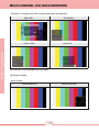
[3] Vector Scope
·Vector Scope
Vector Scope OFF
Vector Scope ON
19
13."2"2
· Vector Scope Size
Small
Full
Vector Scope Position / Blending
: Refer to the Waveform position (P.18) and Waveform Blending (P.19)
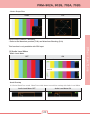
[4] Audio Level Meter
· Audio Level Meter
OFF
ON
Horizontal
Vertical
· Avoid Overlap
In full size WaveForm mode, WaveForm shifts down to avoid the overlap with Audio Level Meter.
Audio Level Meter OFF
Audio Level Meter ON
20
Other Functions
This function is only available with SDI Input.
MULTI-CHANNEL LCD RACK MONITORS
· Group & Channel
Group / Channel (Horizontal)
Group 1
C H1 C H2
Group 2
C H1 C H2
C H3 C H4
C H3 C H4
C H1 C H2
Group 3
C H3 C H4
C H1 C H2
Group 4
C H3 C H4
#This function is only available with SDI Input.
Other Functions
Group / Channel (Vertical)
Group 1
Group 2
Group 3
C H1 C H3 C H1 C H3 C H1 C H3 C H1 C H3
21
Group 4
C H4 C H2 C H4 C H2 C H4 C H2 C H4 C H2
13."2"2
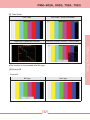
[5] Time Code
Time Code
Time Code + Audio Level Meter
Time Code + WaveForm Full Size
Time Code + SourceID + WaveForm + Audio Level Meter
Other Functions
#This function is only available with SDI Input.
[6] Source ID
· Source ID
BG Type
Char Type
22
MULTI-CHANNEL LCD RACK MONITORS
Other Functions
· Source ID Position
Left Top
Mid Top
Right Top
Left Bottom
Mid Bottom
Right Bottom
· Source ID Color
Black
White
Red
Green
23
Blue
Yellow
13."2"2
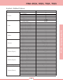
System Default Value
Picture
Color
Remote
System [Page 1]
System [Page 2]
System [Page 3]
System [Button]
# Specifications may be changed without notice.
24
Value
0
0
0
0
0
7.5 IRE
6500K
0
0
0
0
0
0
6500K
Off
Off
Off
Off
White
Analog Channel
Digital A Channel
Digital B Channel
Tally R
Tally G
Blue Only
No
Small
Right Bot
Off
Horizontal
Off
Off
CAM–1
Left Top
Black
Off
Off
Calibrated Value
Zero Scan
4:3
Off
Off
Off
Off
Off
System Default Value
Marker
MEMU
Brightness
Contrast
Chroma
Aperture
Phase
NTSC Setup
Color Temp
Gain Red (1/2/3)
Gain Green (1/2/3)
Gain Blue (1/2/3)
Bias Red (1/2/3)
Bias Green (1/2/3)
Bias Blue (1/2/3)
Color Copy
Line Marker
Center Marker
Safety Area
Maker Mat
Marker Color
PIN 1
PIN 2
PIN 3
PIN 4
PIN 5
PIN 6
System Default
Waveform Size
Waveform Position
Waveform Blending
Audio Level Meter
Audio Channel
Source ID
Source ID Character
Source ID Position
Source ID Color
Time Code
Internal Pattern
Back Light
Scan
Aspect Ratio
Marker
HV Delay
Blue & Mono
Audio Level Meter
Waveform/Vector
MULTI-CHANNEL LCD RACK MONITORS
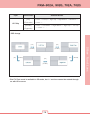
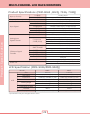
Product Specifications (PRM-902A ,902Q, 702A, 702Q)
Input (1 Screen)
Output (1 Screen)
Input Signal
3 x BNC
1 x BNC
1 x BNC
Composite
S-Video
Component
RGB
HD-SDI
SD-SDI
Composite / S-Video
Product Specification
Analog Input
Signal Formats
Component
/ RGB (SOG)
SMPTE-274M
SMPTE-296M
SMPTE-260M
SMPTE-125M
ITU-R.BT.656
2K Format
SDI Input Signal
Formats
Audio Out
Analog Input
SDI 2 Channel Input
SDI Output (Active Through Out)
1.0Vpp (With Sync)
1.0Vpp (Y With Sync), 0.286Vpp(C)
1.0Vpp (Y With Sync), 0.7Vpp (Pb,Pr)
1.0Vpp (G With Sync), 0.7Vpp (B,R)
1.458Gbps
270Mbps
NTSC (525/59.94i) , PAL (625/50i)
480i (59.94) , 576i (50) , 480P (59.94) , 576P (50)
1080i (60/59.94/50)
1080P (30/29.97/25/24/24sF/23.98/23.98sF)
720P (50/59.94/60)
1080i (60/59.94/50)
1080p (30/29.97/25/24/24sF/23.98/23.98sF)
720p (23.98/24/25/29.97/30/50/59.94/60)
1035i (60/59.94)
480i (59.94)
576i (50)
2048 X 1080 (23.98psf/24psf/23.98psf/24p)
Analog Stereo (Phone Jack)
Internal Speaker 2 X 1W (Stereo)
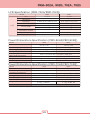
LCD Specification (PRM-902A/PRM-902Q)
Model
LCD
Size
Resolution
Pixel Pitch
Color
Viewing Angle
Luminance of white
Contrast
Display Area
902A
9.0 inch
800 (H) x 480 (V) (15:9)
0.246 (H) X 0.246 (V) mm
16.7M(true), 24bit
H : 160 degrees
V : 140 degrees
600 cd/㎡ (Center)
600:1
196.8 (H) x 118.08 (V) mm
- Specifications may be changed without notice.
25
902Q
9.0 inch
960 (H) x 540 (V) (16:9)
0.207 (H) X 0.207 (V) mm
16.7M(true), 24bit
H : 170 degrees
V : 170 degrees
400 cd/㎡ (Center)
1000:1
198.72 (H) x 111.78 (V) mm
13."2"2
LCD Specification (PRM-702A/PRM-702Q)
Model
LCD
Size
Resolution
Pixel Pitch
Color
Viewing Angle
Luminance of white
Contrast
Display Area
702A
7.0 inch
800 (H) x 480 (V) (15:9)
0.1905 (H) X 0.1905 (V) mm
16.2M(true), 24bit
H : 140 degrees
V : 140 degrees
350 cd/㎡ (Center)
700:1
152.4 (H) x 91.44 (V) mm
702Q
7.0 inch
1024 (H) x 600 (V)
0.15 (H) X 0.15 (V) mm
16.7M(true), 24bit
H : 170 degrees
V : 170 degrees
400 cd/㎡ (Center)
800:1
153.76 (H) x 90.0 (V) mm
Power/Dimensture Specification (PRM-902A/PRM-902Q)
Model
902A
902Q
Power
12V DC, 2.7A
12V DC, 2.4A
Power Consumption (Approx.)
33 Watts
29 Watts
Operating Temperature
0 to 40 (32එ to 104එ)
0 to 40 (32එ to 104එ)
Storage Temperature
TZWGG\WGOTYYඑGGXYYඑP TZWGG\WGOTYYඑGGXYYඑP
Main Body Dimensions
442 x 170 x 63.2 mm (174 x 66.9 x 24.9 inch)
Main Body Dimensions
482 x 178 x 86.7 mm (189.6 x 70 x 34.1 inch)- With Rack Bracket)
Weight
4.1 kg / 9.038 lbs
3.6 kg / 7.936 lbs
Accessory
DC Power Adapter
Power/Dimensture Specification (PRM-702A/PRM-702Q)
Model
702A
702Q
Power
12V DC, 1.6A
12V DC, 1.7A
Power Consumption (Approx.)
20 Watts
21 Watts
Operating Temperature
0 to 40 (32එ to 104එ)
0 to 40 (32එ to 104එ)
Storage Temperature
TZWGG\WGOTYYඑGGXYYඑP TZWGG\WGOTYYඑGGXYYඑP
Main Body Dimensions
442 x 170 x 63.2 mm (174 x 66.9 x 24.9 inch)
Main Body Dimensions
480 x 126 x 45.2 mm (18.89 x 4.96 x 1.78 inch)- With Rack Bracket
Weight
3.2 kg / 7.054 lbs
3.1 kg / 6.834 lbs
Accessory
DC Power Adapter
- Specifications may be changed without notice.
26
LCD Rack Monitor
PRM Series
User's Manual
www.tvlogicusa.com
910 W. Alamada Ave. Burbank CA 91506 USA.
TEL : +1 (818) 567-4900 FAX : +1 (818) 567-4903
www.tvlogic.tv
ACE HIGHEND TOWER 8-12F, 345-4 Gasan-Dong,
GuemChun-Gu, Seoul, 153-802 Korea
Tel : +82-70-8668-6611 Fax : +82-2-6123-3201
www.posƟum.co.kr/www.posƟum.com
PosƟum Bldg. 2F, 433-34 Kalhyun-Dong, Eunpyoung-Gu, Seoul, Korea
Tel : +82-2-354-6055 Fax : +82-2-354-6056