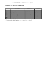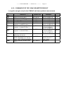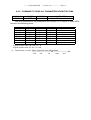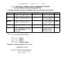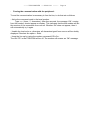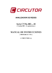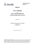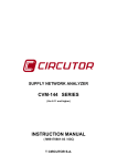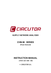
1
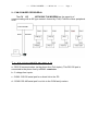
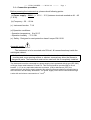
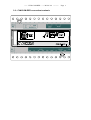
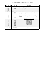
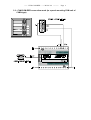
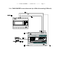
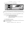
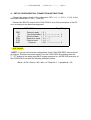
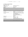
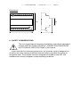
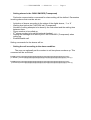
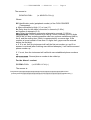
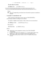
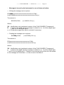
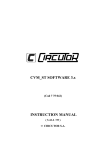
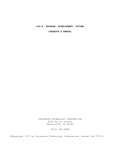
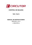
MODEM PERIPHERAL DEVICE CVM-COM-RED (Code 7 70 228 - 7 70 229) USER’S MANUAL (M 981 319 / 01 A) (c) CIRCUTOR S.A. ------ CVM-COM-RED ----- M 981 319 ---------- CVM-COM MANUAL CONTENTS Page 1 Page 1.BASIC INSTRUCTIONS............................................................................................................................ 2 1.1.- Checking the contents of your package....................................................................................................... 2 1.2.- Safety warnings........................................................................................................................................... 2 2.- CVM-COM-RED PERIPHERAL ............................................................................................................... 3 3.INSTALLATION AND STARTUP............................................................................................................ 4 3.1.- Connection procedure ................................................................................................................................. 5 3.2.- CVM-COM-RED connection terminals...................................................................................................... 6 3.3.- CVM-COM-RED connection mode (to a panel mounting CVM unit of CVMk type) ............................... 8 3.4.- CVM-COM-RED connection mode (to a DIN rail mounting CVM unit) .................................................. 9 3.5.- Lighting indications of the CVM-COM-RED........................................................................................... 10 3.6.- CVM-COM-RED push-buttons ................................................................................................................ 10 4.- SETUP CONFIGURATION: CONNECTION INSTRUCTIONS............................................................ 11 5.- TECHNICAL SPECIFICATIONS............................................................................................................ 12 6.- SAFETY CONSIDERATIONS................................................................................................................. 13 7.- MAINTENANCE...................................................................................................................................... 14 8.- TECHNICAL SERVICE........................................................................................................................... 14 APPENDIX A.- CVM-COM-RED COMMUNICATIONS.................................................................................. 15 A.1.- DEMAND FORMAT............................................................................................................................... 15 A.2.- COMMANDS .......................................................................................................................................... 16 A.2.1.- SETTING COMMANDS.................................................................................................................. 16 A.2.2.- COMMANDS FOR THE CVMk PARAMETER READOUT ......................................................... 24 A.2.3.- COMMAND TO READ ALL PARAMETERS FROM THE CVMk............................................... 25 A.2.4.- ADDITIONAL COMMUNICATION COMMANDS FOR THREE BILLING PERIODS (CVM / RED-MAX MODULE) ................................................................................................................................. 26 APPENDIX B .- USING A TERMINAL EMULATING SOFTWARE............................................................... 27 ------ CVM-COM-RED ----- M 981 319 ---------- Page 2 CVM-COM-RED PERIPHERAL 1.- BASIC INSTRUCTIONS 1.1.- Checking the contents of your package This manual is issued to help all the CVM-COM-RED peripheral users to install and apply it in order to get the best from it. After receiving the unit please check following points: (a) The delivered material meets your order specifications. (b) After unpacking, check that the instrument has not been damaged in transit. (c) The standard set includes a user’s manual. 1.2.- Safety warnings The manual you hold in your hands contains information and warnings about the CVM-COM-RED that the user should respect in order to guarantee a proper operation of all the instrument functions and keep its safety conditions. ------ CVM-COM-RED ----- M 981 319 ---------- Page 3 2.- CVM-COM-RED PERIPHERAL The CV CO WITH BUILT-IN MODEM has the capacity of communicating with a 485 type network formed by CVM, CVM-M or other peripheral units. T s st u e t co s sts of fo ow g e e e ts a.- RS-232 communication via the phone line (Full duplex). This RS-232 port is connected to the phone line by a RJ-11 connector. b.- 2 voltage-free inputs. c.- COM1: RS-232 serial port for a direct link to the PC. d.- COM2: RS-485 serial port for a link to the CVM family meters. ------ CVM-COM-RED ----- M 981 319 ---------- Page 4 Description The CVM-COM-RED is an instrument that permits the control of a 485 communication network via the phone line. Main features of this instrument are below listed: - Ability of controlling a 485 communication network from a remote site (via the phone line). Setting up actions over remote metering units. Downloading data from analyzers equipped with internal memory. Detection of alarms through its voltage-free inputs. Automatic call up when alarm conditions are met, so sending a userprogrammable message. 3.- INSTALLATION AND STARTUP The manual you hold in your hands contains information and warnings that the user should respect in order to guarantee a proper operation of all the instrument functions and keep its safety conditions. The instrument must not be powered and used until its definitive assembly inside the switchgear board. If the instrument is not used as manufacturer’s specifications, the protection of the instrument can be damaged. When any protection failure is suspected to exist (for example, it presents external visible damages), the instrument must be immediately powered OFF. In this case contact a qualified service representative. ------ CVM-COM-RED ----- M 981 319 ---------- Page 5 3.1.- Connection procedure Before powering the instrument up, please check following points: (a) Power supply: 230 V~ (+ 10 % / - 15 %) between terminals marked as A1 - A2 (1 & 28). (b) Frequency : 50 ... 60 Hz (c) Instrument burden: 7 VA (d) Operation conditions: - Operation temperature : 0 to 50 ºC - Operation humidity : 75 % RH (e) Safety: Designed to meet protection class II as per EN 61010. Assembly mode: The Instrument is to be mounted onto DIN rail. All connections keep inside the switchgear cabinet. Notice that with the instrument powered on, the terminals could be dangerous to touching and cover opening actions or element removal may allow the access to dangerous parts. The instrument must not be used until this is completely installed. The instrument must be connected to a power supply circuit protected with gl type (IEC 269 ) or M type fuses rated between 0.5 and 2 A. This circuit should be provided with a circuit breaker (I / O) or any equivalent element to connect (ON) or disconnect (OFF) the instrument from the power supply network, this switching element should be placed close to the instrument and be easily accessible. The power supply circuit will be connected through 2 a wire with a minimum cross-section of 1 mm . ------ CVM-COM-RED ----- M 981 319 ---------- 3.2.- CVM-COM-RED connection terminals Page 6 ------ CVM-COM-RED ----- M 981 319 ---------- Te a o a g 1 - 28 A1 - A2 23 24 25 GND 1 2 20 - 19 Ending resistor (RT) 18 17 14 -+ GND Page 7 Co cept Power supply at 230 V~ Common of voltage-free inputs Input of alarm No. 1 Input of alarm No. 2 240 Ω resistor: for the adaptation of line end impedance. (bridge between terminals 20 -- 18 and 19 -- 17) Connection to different peripherals in the 485 type network RS-232 connection to PC 5 6 7 8 9 10 DSR Tx Rx RTS CTS GND Data set ready Transmitted data Received data Request to send Clear to send Common 11 to 13 PRINTER Not in use ------ CVM-COM-RED ----- M 981 319 ---------- Page 8 3.3.- CVM-COM-RED connection mode (to a panel mounting CVM unit of CVMk type) ------ CVM-COM-RED ----- M 981 319 ---------- Page 9 3.4.- CVM-COM-RED connection mode (to a DIN rail mounting CVM unit) ------ CVM-COM-RED ----- M 981 319 ---------- Page 10 3.5.- Lighting indications of the CVM-COM-RED a.- "CO " LED: This led blinks when the peripheral is receiving data from the CVM (“Network”) or from the PC. When no communication exists, then the led keeps off. b.- "C U" LED: When it keeps on, it means that the CVM-COM-RED is running. c.- Each lead indicates a particular modem operation status: - “ C ”: Indication of Data Carrier Detect - “S ” : Indication of data sending process - “ ”: Indication of data reception process (some commands are being sent to the modem) 3.6.- CVM-COM-RED push-buttons - T ST: This push-button permits the default configuration of the RS-232 serial port to be set in the CVM-COM-RED: Peripheral 99 / 9.600 baud / 8 bits / 1 stop bit / Non ------ CVM-COM-RED ----- M 981 319 ---------- Page 11 4.- SETUP CONFIGURATION: CONNECTION INSTRUCTIONS - Connect the power supply of the instrument, 230 V a.c. (+ 10 % / - 15 %), to the terminals marked as A1 - A2 ( 1 and 28 ). - Connect the RS-232 output of the CVM-COM to one of the serial ports of the PC unit, according to the below arrangement: CVM -COM DSR Tx Rx RTS CTS GND <--------------------> Data set ready Transmitted data Received data Request to send Clear to send Common PC ( DB-9 ) ( 5 ) ( 6 ) --------------------> ( 7 ) --------------------> ( 8 ) ---- ( 9 ) ---- ( 10 ) -------------------> . 2 3 . . 5 - SOFTWARE. NOTE : If you do not know the configuration of the CVM-COM-RED, then proceed as follows: Remove the power supply from the CVM-COM. By pressing then the "T ST" button at the same time that it is again powered on, the RS-232 serial port of the CVM-COM is set with the following standard values: Baud = 9.600 / Parity = NO / bits = 8 / Stop bits = 1 / peripheral = 99 ------ CVM-COM-RED ----- M 981 319 ---------- Page 12 5.- TECHNICAL SPECIFICATIONS Power supply circuit: Voltage ....................................... Voltage tolerance .............................. Frequency ........................................ Burden ......................... Operation temperature ................. Single-phase 230 V a.c. +10 % / -15 % 50 ... 60 Hz 7 VA 0 to 50 ºC Digital inputs ....................... 2 contact-type inputs Constructive characteristics Case type .................................... Modular type, self-extinguishing, plastic casing. Connection terminals.......................... Metallic terminals with "posidraft" screws Assembly .................................... To be fitted onto symmetric rail as per DIN 46277 (EN 50022) Screw fixing also possible (Ø 4,2 mm passing hole for fixing purposes) Frontal cover ..................................... Lexan IP degree ................................... Built-in relay: IP 41 Terminals : IP 20 Dimensions ................................ 140 x 70 x 110 mm (8 module size as per DIN 43 880) Safety ................................... Class II, as per EN 61010 Standards IEC 664, VDE 0110, UL 94 ------ CVM-COM-RED ----- M 981 319 ---------- Page 13 110 45 Dimensions : 140 70 6.- SAFETY CONSIDERATIONS The user should take into account all installation instructions indicated in sections INSTALLATION & STARTUP, CONNECTION PROCEDURE and TECHNICAL SPECIFICATIONS of this manual. Notice that with the instrument powered on, the terminals could be dangerous to touching, and cover opening or element removal actions may allow the access to dangerous parts. The analyzer has been designed and tested to meet IEC 348 standard and is factory-shipped in proper operating conditions. ------ CVM-COM-RED ----- M 981 319 ---------- Page 14 7.- MAINTENANCE The CVM-COM-RED does not require any special maintenance. No adjustment, maintenance or repairing action should be done over the instrument open and powered and, should those actions are essential, high-qualified operators must perform them. Before any adjustment, replacement, maintenance or repairing operation is carried out, the instrument must be totally disconnected from any power supply source. When any protection failure is suspected to exist, the instrument must be immediately put our of service. The design of the analyzer permits its quick replacement in case of failure. 8.- TECHNICAL SERVICE For any inquiry about the instrument performance or If any failure happens, please contact to CIRCUTOR’s technical service. C C TO S A Afte sa es se v ce c / epa to , 9 08223 T ASSA 34 93 5 9 00 Te fax 34 93 5 9 a ce t a c c to es ------ CVM-COM-RED ----- M 981 319 ---------- Page 15 APPENDIX A.- CVM-COM-RED COMMUNICATIONS The CVM-COM -RED can be directly connected to a PC, either via RS-232 or via the telephone line. IMPORTANT REMARK!: We must remark that the communication parameter setting for the RS-232 and the RS-485 must be totally identical, otherwise, the answer for the communication command will be an error. In terms of the network of instruments connected to the RS-485 the situation is alike, that is, all communication parameters must be equal for all the units (excepts for the peripheral no.). When the network is inquired with the identification code (peripheral no). 00, then the command will not be transferred to the network but only the CVM-COM-RED will answer. PROTOCOL: Question / Answer A.1.- DEMAND FORMAT The demand format is: $PPCCCAA... ch [LF] (example = $01RVI76) The answer format is: $PPAA... ch [LF] $ PP CCC AA Ch [ LF] Any message starts with this symbol (ASCII- 36). The identification code (peripheral number) (01 to 99) for the portable the CVM unit (decimal- ASCII) COMMAND ARGUMENT (Decimal- ASCII). CHECK-SUM : Check-sum of all the elements forming the message. It is calculated by the decimal addition of all the previous bytes in ASCII and then translating the result into hexadecimal. Two digits are taken. example = $01RVI --> 36 + 48 + 49 +82 + 86 + 73 =374 374 decimal or 176 hexad. CHECK-SUM = 76 ----> $01RVI76 [LF] LINE FEED indicates the end of the message (ASCII 10). ------ CVM-COM-RED ----- M 981 319 ---------- Page 16 A.2.- COMMANDS A.2.1.- SETTING COMMANDS COMMAND DEF RRS WRS CONCEPT Write default parameters Read communications (*) Write communications (*) QUESTION ANSWER $pp DEF ch $PP ACK ch $pp RRS ch $pp 13 digits ch $pp 13 digits ch $PP ACK ch (*) NOTE : The RRS / WRS command (communications): - 2 digits peripheral number / 1 digit Parity / 1 digit length / 1 digit Stop bits/ 4 digits Baud rate SERIAL RS-232 output / 4 digit Baud rate 2nd RS-485 output COMMAND VER INI RNR WNR CONCEPT Read CVM-COM version Reset Read number of rings Write number of rings QUESTION $pp VER ch $pp INI ch $pp RNR ch $pp WNR 2 dig ch ANSWER $pp 4 digits ch ------$pp 2 dig + ch $pp ACK ch ------ CVM-COM-RED ----- M 981 319 ---------- - Page 17 Setting alarms in the CVM-COM-RED (Transparent) Particular communication commands for alarm setting will be defined. Parameters involving alarms that must be set are: - Activation of alarms according to the status of the digital alarms, ‘1’ or ‘0’ Waiting time before the CVM-COM call (Transparent). Number of calling attempts to be done by the instrument and the waiting time between them. Phone number to be called up. 2nd phone number to be called (optional function) Setting the message to be sent by the CVM-COM-RED (Transparent) when calling up. Enable/Disable call. Setting commands for the alarms will be: - Setting the call according to the alarm condition. The user can optionally set the modem to call two phone numbers up. This command will be as follows: $XXAL1yzzmnnnpppppppppppppppppppppppppvqqqqqqqqqqqqqqqqqqqqqqqq<CHK> (or #XXAL1yzzmnnnpppppppppppppppppppppppppvqqqqqqqqqqqqqqqqqqqqqqqq<Ctrl+j>) $XXAL2yzzmnnnpppppppppppppppppppppppppvqqqqqqqqqqqqqqqqqqqqqqqq<CHK> (or #XXAL2yzzmnnnpppppppppppppppppppppppppvqqqqqqqqqqqqqqqqqqqqqqqq<Ctrl+j>) ------ CVM-COM-RED ----- M 981 319 ---------- Page 18 The answer is: $XXACK<CHK> (or #XXACK<Ctrl+j>) Where: XX: Identification code (peripheral number) of the CVM-COM-RED (Transparent). y: Alarm activation by High (‘1’) or Low (‘0’). zz: Delay time for the alarm connection in seconds (0..99 s). m: Number of attempts (0..9). nnn: Delay time between successive attempts in seconds (0..999 s). ppppppppppp: Phone number to be call up. Phone numbers up to 25 digits can be set, so also including possible calls from a phone switchboard (that is, the 0, and the waiting time, which is represented by a comma sign. If the number to be set consist of less than 11 digits, then, gaps must be entered before the first digit. v: If ‘0’ is set, then the instrument will call the first set number up, and if no answer is received (after finishing user-defined attempts), it will call the second phone number up. If ‘1’ is set, then the instrument will call both user-established phone numbers up. qqqqqqqqqqq: Second phone number to be called up. For the Alarm 1 readout: $XXRA1<CHK> (or #XXRA1<Ctrl+j>) The answer is: $XXyzzmnnnpppppppppppppppppppppppppvqqqqqqqqqqqqqqqqqqqqqqqqRR<CHK> (or #XXyzzmnnnpppppppppppppppppppppppppvqqqqqqqqqqqqqqqqqqqqqqqqRR<Ctrl+j>) ------ CVM-COM-RED ----- M 981 319 ---------- Page 19 For the Alarm 2 readout: $XXRA2<CHK> (or #XXRA2<Ctrl+j>) $XXyzzmnnnpppppppppppppppppppppppppvqqqqqqqqqqqqqqqqqqqqqqqqRR<CHK> (ó #XXyzzmnnnpppppppppppppppppppppppppvqqqqqqqqqqqqqqqqqqqqqqqqRR<Ctrl+j>) Where: RR: ON or OF, depending on whether the call activation by alarm is enabled or disabled. - Command for enable/disable call. If the command of call setting is send, then the CVM-COM-RED is automatically enabled for calling in case of alarm. To enable or disable the call action in case of alarm, the user should set: $XX PHOyzz<CHK> (or #XXPHOyzz<Ctrl+j>) The answer is: $XXACK<CHK> (or #XXACK<Ctrl+j>) Where: XX: Identification code (peripheral number) of the CVM-COM-RED (Transparent) y: it refers to the alarm to be activated, so, 1 is for the alarm linked to the digital input 1, and 2 is for the alarm linked to the digital input 2. Zz: ‘ON’ enables call by alarm function, and, ‘OF’ disable call by alarm function. ------ CVM-COM-RED ----- M 981 319 ---------- Page 20 - Message to be sent by the instrument in case of alarm activation. • Writing the message sent via phone: $XXWMIb cccccccccccccccccccccccccccccc<CHK> (or #XXWMIbcccccccccccccccccccccccccccccc<Ctrl+j>) The answer is: $XXACK<CHK> (or #XXACK<Ctrl+j>) Where: XX: Identification code (peripheral number) of the CVM-COM-RED (Transparent). B: it refers to the digital input the message is related to, so, 1 is for the digital input 1, and 2 is for the digital input 2. c..c: 30 characters (gaps can also be included if necessary). • Reading the message sent via phone $XXRMIy<CHK> (or #XXRMIy<Ctrl+j>) The answer is: $XXcccccccccccccccccccccccccccccc<CHK> (or #XXcccccccccccccccccccccccccccccc<Ctrl+j>) Where: XX: Identification code (peripheral number) of the CVM-COM-RED (Transparent) y: it refers to the digital input the message is related to, so, 1 is for the digital input 1, and 2 is for the digital input 2. Therefore, the returning value will be the one related to the message set in the alarm 1, or the one set in the alarm 2. ------ CVM-COM-RED ----- M 981 319 ---------- - Counters of alarm events. $XXALA<CHK> (or #XXALA<Ctrl+j>) The answer is: $XXyyyyzzzz<CHK> (or #XXyyyyzzzz<Ctrl+j>) Where: yyyy:Times that the alarm 1 has been activated. zzzz: Times that the alarm 2 has been activated. • Deleting alarm events counters: $XXCLAy<CHK> (or #XXCLAy<Ctrl+j>) The answer is: $XXACK<CHK> (or #XXACK<Ctrl+j>) Where: y: it refers to the alarm events counter to be reset to zero. Page 21 ------ CVM-COM-RED ----- M 981 319 ---------- - Page 22 Reading the digital input status. $XXINP<CHK> (or #XXINP<Ctrl+j>) The answer is: $XXyz<CHK> (or #XXyz<Ctrl+j>) Where: y: z: Status of the digital input 1. Status of the digital input 2. Remarks: 1) Alarm events counters will increase their value always that an alarm condition is detected, regardless the call is made or not. 2) Alarm events counters will be reset to zero if the user delete these counters by using the applicable communication command, but also, in case of oversize. 3) The maximum value allowable for any alarm events counter is 9999. Once this value is reached, then the counter will be automatically reset to zero. ------ CVM-COM-RED ----- M 981 319 ---------- Page 23 SUMMARY OF SETTING COMMANDS COMMAND ALi * RAi * PHO WMIi* RMIi * ALA CLAi * INP CONCEPT Set alarm calls Read alarm calls Enable/Disable alarms Write alarm message Read alarm message Counter of alarm events Delete counter of alarm events Read digital input status QUESTION ANSWER $ppALi+60 digits ch $PP ACK ch $pp RAi ch $ppPHO+3 digits ch $ppWMIi+30 digit ch $ppRMIi $ppALA $ppCLAi $ppINPi $PP ACK ch $PP ACK ch $PP 30 digits ch $PP 8 digits ch $PP ACK ch $pp 2 digits ch * “i” refers to the digital input no. (i=1 ⇒ alarm 1; i=2 ⇒ alarm 2) $pp 60 digits ch ------ CVM-COM-RED ----- M 981 319 ---------- Page 24 A.2.2.- COMMANDS FOR THE CVMk PARAMETER READOUT (*) negative energies only for the CVMk-4C unit (four-quadrant measurement) COMMAND CONCEPT QUESTION RVI ROI RAI RPI RFI RWH (*) RLH (*) Read V line-to-neutral INST Read V line-to-line INST Read Current INST Read Active power INST Read PF INST Read active energy (positive, negative - in absolute value -) Read inductive energy (positive, negative - in absolute value -) $pp $pp $pp $pp $pp $pp RCH (*) Read capacitive energy (positive, negative - in absolute value -) $pp RCH ch RCL Read clock in real time dd/mm/yy hh:mm:ss Read maximum demand value: DATE, MAXIMUM (from the last reset), LAST PERIOD MAXIMUM Delete maximum demand value pd = 0 $pp RCL ch RMD CMD RVI ch ROI ch RAI ch RPI ch RFI ch RWH ch $pp RLH ch $pp RMD ch $pp CMD ch ANSWER $pp 4 x 9 digits ch $pp 4 x 9 digits ch $pp 4 x 9 digits ch $pp 4 x 9 digits ch $pp 4 x 3 digits ch $pp 1 x 9 digits ch $pp 2 x 9 digits ch $pp 1 x 9 digits ch - For the CVMk-4C: $pp 2 x 9 digits ch $pp 1 x 9 digits ch - For the CVMk-4C: $pp 2 x 9 digits ch $pp 17 characters ch $pp 35 digits ch xx/xx/xx xx:xx:xx + 9 dig + 9 dig $pp ACK ch UNIT V V mA W x 100 Wh varLh varCh ------ CVM-COM-RED ----- M 981 319 ---------- Page 25 A.2.3.- COMMAND TO READ ALL PARAMETERS FROM THE CVMk COMMAND RAL CONCEPT QUESTION ANSWER SIZE Read TOTAL $pp RAL ch $pp + 244 bytes + ch With this parameter all the parameters are inquired: 30 x 8 bytes in hexa-ASCII format in the following order: [ 0 ] L1 [ 4 ] L1 [ 8 ] L1 [ 12 ] L1 [ 16 ] L1 [ 20 ] L1 [ 24 ] L1 [ 1 ] L2 [ 5 ] L2 [ 9 ] L2 [ 13 ] L2 [ 17 ] L2 [ 21 ] L2 [ 25 ] L2 [ 2 ] L3 [ 6 ] L3 [ 10 ] L3 [ 14 ] L3 [ 18 ] L3 [ 22 ] L3 [ 26 ] L3 [3] M [7] M [ 11 ] M [ 15 ] III [ 19 ] III [ 23 ] III [ 27 ] M [ 28 ] [ 29 ] III Voltage line-to-line Voltage line-to-neutral Current Active power Inductive power Capacitive power Power factor (*) Frequency Apparent power - 2 bytes: current units 00 - mA / 01 - A - 2 bytes: power units 00 - W / 01 - kW (*) - Power factor ( x 100 ): When capacitive then 200 is added 0 ---------------------------- 100 ------------------------ 200 +0.0 Ind 1.0 Cap - 0.0 ------ CVM-COM-RED ----- M 981 319 ---------- Page 26 A.2.4.- ADDITIONAL COMMUNICATION COMMANDS FOR THREE BILLING PERIODS (CVM / RED-MAX MODULE) (*) negative energies only for the CVMk-4C unit (four-quadrant measurement). COMMAND CONCEPT QUESTION RWHXn (*) RLHXn (*) Read active energy (positive, negative - in absolute value -) Read inductive energy (positive, negative - in absolute value -) RCHXn (*) Read capacitive energy (positive, $pp RCHXn ch negative - in absolute value -) CMDXn Delete maximum demand value pd=0 Read maximum demand value: DATE, MAXIMUM (from the last reset), LAST PERIOD MAXIMUM RMDXn $pp RWHXn ch $pp RLHXn ch $pp CMDXn ch $pp RMDXn ch ! - "n" is the inquired tariff number: 0 -------------- Tariff 1 1 --------------- Tariff 2 2 -------------- Tariff 3 3 --------------- All three tariffs Example: to inquire all three kWh counters: $00RWHX3 [ch] [LF] - where "a" set the size of the answer: a= 1 if n= 0, 1 or 2 a = 3 if n= 3 ANSWER $pp a x 9 digits ch $pp 2a x 9 dig ch $pp a x 9 digits ch - For the CVMk-4C : $pp 2a x 9 dig. ch $pp a x 9 digits ch - For the CVMk-4C : $pp 2a x 9 dig. ch $pp ACK ch $pp a x 35 digits ch xx/xx/xx xx:xx:xx xxxxxxxxx (9 dig) xxxxxxxxx (9 dig) UNIT Wh varLh varCh ------ CVM-COM-RED ----- M 981 319 ---------- Page 27 APPENDIX B .- USING A TERMINAL EMULATING SOFTWARE - Setting communication with the CVM-COM-RED: - Set the local serial port of the PC up with the same parameters set in the modem at the other side of the phone line. - Enter the calling command ATD<phone number of the CVM-COM-RED><Cr> (Cr: carriage return) - Wait for a CONNECT message on the screen, coming from the modem. When this message appears, commands of the CVM-COM-RED can then be entered. - Active the local echo to see all data being sent to the CVM-COM-RED: Select the echo option. - To set the communication: - A < Ctrl + J > message (press the J key simultaneously with the Ctrl one) is sent to the CVM-COM-RED peripheral. - The demand format is: #PPCCCAA< Ctrl + J >. All commands start with #PP, where PP stands for the identification code (peripheral number). CCC = COMMAND and AA = argument. OT : Whether the peripheral number is not known, then the command can be sent with the identification code 00, since for the CVM-COM-RED only exists one remote peripheral. - The answer format is: #PPAA... CRLF The commands with this special character # which are allowed are only those that do not modify any critical parameter of the SETUP. In this case, the instrument does not check the check-sum. The answer always ends in CRLF to make easier its visualization. ------ CVM-COM-RED ----- M 981 319 ---------- - Page 28 Freeing the communication with the peripheral: To end the communication is necessary to free the line; to do that act as follows: - Active the command mode in the local modem. Type +++ ( three “+” characters). After few seconds, the message ‘OK’, coming from the modem, should appear on display. This indicates that the this modem will be the receiver of the commands from now on. Whether ‘OK’ does not appear, then it will automatically try it again. - Unable the local echo or, otherwise, all characters typed from now on will be doubly displayed. Deselect the option > Echo . - Hung the line up by typing the modem command ATH<Cr>. The led “CD” in the CVM-COM will be off. The modem will answer an ‘OK’ message.