1
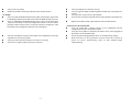
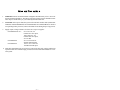
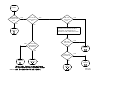
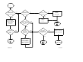
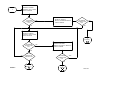
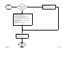
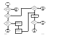
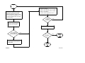
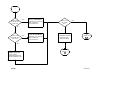
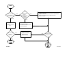
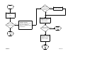
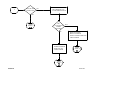
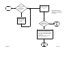
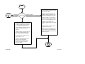
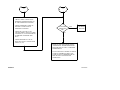
|__ __|__ __| GE Fanuc Automation Programmable Control Products Î GE Fanuc Automation P.O. Box 8106 Charlottesville, VA 22906 GFZ–0086 Î Series 90 TM–70 Programmable Controller Troubleshooting Guide |__ __|__ __| |__ __|__ __| __|__ __| Î GE Fanuc Automation Programmable Control Products Series 90 TM–70 Programmable Controller Troubleshooting Guide GFZ–0086 |__ November1993 |__ __|__ __| This document is based on information available at the time of its publication. While efforts have been made to be accurate, the information contained in this document does not purport to cover all details or variations in hardware and software, nor to provide for every contingency in connection with installation, operation and maintenance. This document may describe features not present in all hardware and software systems. GE Fanuc Automation assumes no obligation of notice to holders of this document with respect to changes subsequently made. GE Fanuc Automation makes no representation or warranty, expressed, implied, or statutory with respect to, and assumes no responsibility for the accuracy, completeness or usefulness of the information contained in this document. No warranties of merchantability of fitness for purpose shall apply. Stand clear of controlled equipment when power is applied. If the problem is intermittent, sudden unexpected machine motion could occur, causing injury. Also reference NFPA 70E Part II for additional guidelines for safety practices. ÁÁÁÁÁÁÁ ÁÁÁÁÁÁÁÁ ÁÁÁÁÁ ÁÁÁÁÁÁÁ ÁÁÁÁÁÁÁÁ ÁÁÁÁÁ ÁÁÁÁÁÁÁ ÁÁÁÁÁÁÁÁ ÁÁÁÁÁ ÁÁÁÁÁÁÁ ÁÁÁÁÁÁÁÁ ÁÁÁÁÁ ÁÁÁÁÁÁÁ ÁÁÁÁÁÁÁÁ ÁÁÁÁÁ ÁÁÁÁÁÁÁ ÁÁÁÁÁÁÁÁ ÁÁÁÁÁ The following are trademarks of GE Fanuc Automation North America, Inc. Alarm Master PROMACRO GEnet Series 90 Modelmaster ProLoop Workmaster CIMSTAR Series Six Logicmaster CIMPLICITY 90–ADS Series Three CIMPLICITY PowerTRAC Genius Power TRAC Helpmate CIMPLICITY Series One Genius VuMaster Series Five Never reach into a machine to operate a switch since unexpected motion could occur, causing injury. Remove all electrical power at the Main Power Disconnect to ensure total power removal. Copyright 1993 GE Fanuc Automation North America, Inc. All Rights Reserved. |__ __|__ Always remove power before inserting or removing modules, or before connecting I/O cabling. __| |__ __|__ __| This guide describes a logical sequence for troubleshooting your Series 90–70 programmable controller. The Series 90–70 PLC is a member of the Series 90TM family of programmable logic controllers from GE Fanuc Automation. This is the first release of this Troubleshooting Guide. Included are models CPU models 731, 732, 771, 772, 781, 782, and CPM914. CPU models 788 and 789 are also included; however, troubleshooting these models may require techniques beyond the scope of this Troubleshooting Guide. At GE Fanuc Automation, we strive to produce quality technical documentation. After you have used this troubleshooting guide, please take a few moments to write us with your comments and suggestions. Our address is: Manager Technical Publications, GE Fanuc Automation. PO Box 8106, Charlottesville, VA 22906 Drake C. Fink Sr. Staff Systems Engineer Series 90 TM–70 Programmable Controller Installation Manual (GFK–0262). Logicmaster TM 90–70 Programming Software User’s Manual (GFK–0263) Series 90 TM–70 Programmable Controllers Reference Manual (GFK–0265) Series 90 TM–70 Programmable Controller Data Sheets (GFK–0600) |__ __|__ __| |__ __|__ __| |__ __|__ __| Although your PLC CPU may be running in RUN/IO ENABLED mode, and you may have communications between the PLC and Logicmaster 90, the system may not be operating correctly. The following pages suggest some areas to investigate: Grounding: D Verify all power supply mounting screws are tightened. D Verify the green grounding wire provided with the power supply is securely attached to the rack grounding stud. D Verify all racks are grounded to a common ground. Reference the System Grounding Procedures in the Series 90–70 Programmable Controller Installation Manual (GFK–0262) for additional information. Loss of Rack Fault: D Verify all inter–rack cables are securely connected on both ends. Verify cables connect to all racks. D Verify the bottom connector on the last Bus Receiver Module has a terminator plug. (No terminator is needed on a Bus Transmitter Module when there are no expansion racks.) D Verify all power supplies are powered on (Green LEDs on). Follow the same troubleshooting procedures for expansion racks power supplies as you use for the main rack. D Verify each expansion rack has a unique address. ONLY the rack containing the CPU is address zero. All other racks are in the range 1 to 7. NO rack is in the range 8 to 15. D D D D Other Faults: D Position the cursor on the fault. Using Release 4 Logicmaster, press the ZOOM (F10) key. Read the fault explanation and follow the suggestions for eliminating the fault. No Input: D Verify no LOSS OF MODULE fault for the module containing the input in the I/O Fault Table. Replace the module if the LOSS OF MODULE fault is present. D D D D D D –1– If all the above are true and you still have LOSS OF RACK, then: Power off all racks. Remove expansion rack cable from bottom connector on the Bus Transmitter Module (BTM) in the main rack. Power on the main rack. You should see LOSS OF RACK faults for all expansion racks in the PLC Fault Table. Place the PLC in RUN mode. (If you have configured the LOSS OF RACK fault to be FATAL, you will have to clear the PLC Fault Table before you can place the PLC in RUN mode.) Power off all racks. Connect expansion cable to next rack, so previous rack is still in the chain. Connect terminator plug to bottom connector on BRM. Power on all expansion racks. Power on main rack. LOSS OF RACK faults for all non–connected expansion racks should appear in the PLC CPU Fault Table. Place PLC in RUN mode. Replace BRM and cable if LOSS OF RACK fault persists. Continue debugging the expansion rack chain one rack at a time until all racks have been added to the chain and no LOSS OF RACK faults occur. Verify no ADDITION OF MODULE fault occurs in the I/O Fault Table when you power cycle the PLC or store the configuration to the PLC. If so, the module physically resides in the slot, but is not present in the PLC configuration. Add the module to the configuration and restore the configuration. Verify the %I address assigned for the input in the configuration is the same %I address as used in the program. Verify pins in the VME bus connector are not bent or corroded. Verify the input device functions correctly. Verify wiring from input device through terminal strip to input module is intact. Verify presence of power at the input device. D D Verify no fuses are blown. Replace the module if other input channels on this module function. No Output: D Verify no LOSS OF MODULE fault for the module containing the output in the I/O Fault Table. Replace the module if the LOSS OF MODULE fault is present. D Verify no ADDITION OF MODULE fault occurs in the I/O Fault Table when you power cycle the PLC or store the configuration to the PLC. If so, the module physically resides in the slot, but is not present in the PLC configuration. Add the module to the configuration and restore the configuration. D D D Verify the %Q address assigned for the output in the configuration is the same %Q address as used in the program. Verify pins in the VME bus connector are not bent or corroded. Verify fuse on output module (if present) is not blown. –2– D D D D D Verify the output device functions correctly. Verify wiring from output module through the terminal strip to the field device is intact. Verify presence of power at the output module. Verify no fuses are blown in the path from the output module to the field device . Replace the module if other output channels on this module function. Genius Devices Do Not Function: D Verify the Genius Bus Controller appears in the configuration and the configuration in the PLC and LM90 are equal. D Verify the %I/%Q addresses assigned to the Genius device in the configuration match those used in the ladder logic. D Follow the general debug guidelines above for No Input and No Output. D Refer to the Series 90–70 Programmable Controller Genius Bus Controller & Genius I/O System Troubleshooting Guide for more detailed Genius Troubleshooting. 1. WARNING: Do not discard the lithium–manganese dioxide battery in fire. Do not attempt to discharge the battery. The battery may burst or burn or release hazardous materials. Dispose of the battery as you would any hazardous material. 2. CAUTION: After a power fault, the system will come back on in the mode (STOP/ IOENABLED, STOP/IODISABLED, RUN/IOENABLED, RUN/IODISABLED) in which it was operating before power loss, unless a fatal fault occurs during the power up process. 3. Supply (input) voltage tolerances for Series 90–70 power supplies: IC697PWR710 & 711: 93 to 132 VAC, for nominal 115 VAC input; 180 to 264 VAC, for nominal 230 VAC input; 47 to 63 HZ IC697PWR722 21.6 to 26.4 VDC for 24VDC nominal input IC697PWR732 122.5 to 137.5 VDC for 125VDC nominal input 4. Total cable length must not exceed 50 feet between the CPU rack (rack 0) and the last expansion rack. No termination plug is needed on a Bus Transmitter Module in a one– rack system. –3– ÁÁÁÁÁ ÁÁÁÁÁ ÁÁÁÁÁ ÁÁÁÁÁÁ Á ÁÁÁÁÁÁ ÁÁÁÁÁÁ ÁÁÁÁÁÁ ÁÁÁÁÁÁ Á ÁÁÁÁÁ Á ÁÁÁÁÁ ÁÁÁÁÁ ÁÁÁÁÁ START IS POWER SUPPLY LED ON? YES NO ÁÁÁÁÁÁÁ ÁÁÁÁÁÁÁ Á ÁÁÁÁÁÁÁ ÁÁÁÁÁÁÁ ÁÁÁÁÁÁÁ IS TOP CPU LED STEADY ON? YES NO ÁÁÁÁÁÁÁ Á ÁÁÁÁÁÁÁ ÁÁÁÁÁÁÁ ÁÁÁÁÁÁÁ ÁÁÁÁÁÁÁ YES IS TOP CPU LED ALWAYS BLINKING? NO ÁÁ ÁÁÁÁÁ ÁÁÁÁ Á ÁÁ ÁÁÁÁ ÁÁÁÁÁ ÁÁÁÁ ÁÁÁÁÁ PAGE 1 ARE ALL 3 CPU LEDS ON? YES NO TOGGLE CPU SWITCH TO RUN (UP) POSN. IF SWITCH IS UP, TOGGLE IT OFF, THEN ON AGAIN 1 (PAGE 2) 7 (PAGE 8) ÁÁÁÁÁÁÁ ÁÁÁÁÁÁÁ ÁÁÁÁÁÁÁÁ ÁÁÁÁÁÁÁ ÁÁÁÁÁÁÁ ÁÁÁÁÁÁÁÁÁÁ Á ÁÁÁÁÁÁÁÁÁÁ ÁÁÁÁÁÁÁÁÁÁ ÁÁÁÁÁÁÁÁÁÁ ÁÁÁÁÁÁÁ Á ÁÁÁÁÁÁÁ ÁÁ ÁÁÁÁÁÁÁ ÁÁÁÁÁ ÁÁÁÁÁÁÁ ÁÁÁÁÁ ÁÁÁÁÁÁÁ ÁÁÁÁÁÁÁ Á ÁÁÁÁÁ ÁÁÁÁÁÁÁ ÁÁÁÁÁÁÁ ÁÁÁÁÁÁÁ ÁÁÁÁÁ Á ÁÁÁÁÁÁÁ ÁÁÁÁÁ ÁÁÁÁÁ Á ÁÁÁÁÁ ÁÁÁÁÁ ÁÁÁÁÁ ÁÁÁÁÁ ÁÁÁÁÁ 8 (PAGE 9) ARE ALL 3 CPU LEDS ON? YES 13 (PAGE 13) NO ONLY TOP CPU LED ON? YES NO 4 (PAGE 5) 6 (PAGE 7) DIAG70A GFZ-0086 ÁÁÁÁÁ ÁÁÁÁÁ ÁÁÁÁÁ ÁÁÁÁÁÁÁÁ Á ÁÁÁÁÁÁÁÁ ÁÁÁÁÁÁ ÁÁÁÁÁÁÁÁÁ ÁÁÁÁÁÁ Á ÁÁÁÁÁÁÁÁ ÁÁÁÁÁÁ ÁÁÁÁÁÁÁÁ ÁÁÁÁÁÁ ÁÁÁÁÁÁ ÁÁÁÁÁÁÁÁ Á ÁÁÁÁÁÁÁÁ ÁÁ ÁÁÁÁÁÁÁ Á ÁÁÁÁÁÁÁÁ ÁÁÁÁÁÁÁ ÁÁÁÁÁÁÁÁ ÁÁÁÁÁÁÁ ÁÁÁÁÁÁÁÁ ÁÁÁÁÁÁÁ ÁÁÁÁÁÁÁÁ ÁÁÁÁÁÁÁÁ ÁÁÁÁÁÁÁ Á ÁÁÁÁÁÁ ÁÁ ÁÁÁÁÁÁÁ ÁÁÁÁÁÁ Á ÁÁÁÁÁÁÁ ÁÁÁÁÁÁ Á ÁÁÁÁÁÁÁ ÁÁÁÁÁÁ ÁÁÁÁÁÁÁ ÁÁÁÁÁÁ ÁÁÁÁÁÁ ÁÁ ÁÁÁÁÁ Á ÁÁÁÁÁÁ ÁÁÁÁÁÁ ÁÁÁÁÁ ÁÁÁÁÁÁ ÁÁÁÁÁ ÁÁÁÁÁÁ 1 POSITION OF PWR SUP ON/ OFF SWITCH? ON IS VOLTAGE APPLIED TO PWR SUP? NO YES OFF MOVE POWER SUPPLY SWITCH TO ON (UP) POSITION IS SUPPLY A DUAL–VOLTAGE SUPPLY? NO YES IS POWER SUPPLY LED ON? YES START (PAGE 1) PAGE 2 NO DOES SUPPLY VOLTAGE = SETTING? NO CHANGE POWER SUPPLY JUMPER TO AGREE WITH SUPPLY VOLTAGE. YES ÁÁÁÁÁÁÁ ÁÁÁÁÁÁÁ Á ÁÁÁÁÁÁÁ ÁÁÁÁÁÁÁ Á ÁÁÁÁÁÁÁ ÁÁÁÁÁÁÁ Á ÁÁÁÁÁÁÁ ÁÁÁÁÁÁÁ ÁÁÁÁÁÁÁ ÁÁÁÁÁÁÁ ÁÁÁÁÁÁÁ Á ÁÁÁÁÁÁÁ ÁÁÁÁÁÁÁ ÁÁÁÁÁÁÁ ÁÁÁÁÁÁÁ Á ÁÁÁÁÁ Á ÁÁÁÁÁ ÁÁÁÁÁ IS LINE FUSE BLOWN? NO YES REPLACE LINE FUSE IS SUPPLY VOLTAGE IN TOLERANCE? YES 2 (PAGE 3) ÁÁÁÁÁÁÁ ÁÁÁÁÁÁÁ Á ÁÁÁÁÁÁÁ ÁÁÁÁÁÁÁ Á ÁÁÁÁÁ Á ÁÁÁÁÁ ÁÁÁÁÁ ÁÁÁÁÁÁÁ ÁÁÁÁÁÁÁ Á ÁÁÁÁÁÁÁ ÁÁÁÁÁÁÁ ÁÁÁÁÁÁÁ Á ÁÁÁÁÁ Á ÁÁÁÁÁ ÁÁÁÁÁ APPLY PROPER VOLTAGE START (PAGE 1) NO CORRECT FAULTY SUPPLY VOLTAGE 1 (THIS PAGE) DIAG70B ÁÁÁÁÁ ÁÁÁÁÁ ÁÁÁÁÁ ÁÁÁÁÁ 2 ÁÁÁÁÁÁÁ ÁÁÁÁÁÁÁ ÁÁÁÁÁÁÁÁ ÁÁÁÁÁÁÁ ÁÁÁÁÁÁÁ Á ÁÁÁÁÁÁÁ ÁÁÁÁÁÁÁ ÁÁÁÁÁÁÁ ÁÁÁ ÁÁÁÁÁÁÁ ÁÁ Á ÁÁÁÁÁÁÁ Á ÁÁÁÁÁÁÁ ÁÁÁÁÁÁÁ ÁÁÁÁÁÁÁ ÁÁÁÁÁÁÁ Á ÁÁÁÁÁÁÁ ÁÁÁÁÁÁÁ ÁÁÁÁÁÁÁ ÁÁÁÁÁÁÁ ÁÁÁÁÁÁÁ Á ÁÁÁÁÁÁÁ ÁÁÁÁÁÁÁ ÁÁÁÁÁÁÁ ÁÁÁÁÁÁÁ ÁÁÁÁÁ Á ÁÁÁÁÁ ÁÁÁÁÁ · REMOVE POWER · REMOVE ALL CARDS · APPLY POWER IS POWER SUPPLY LED ON? NO YES · REMOVE POWER · INSTALL NEXT CARD · APPLY POWER IS POWER SUPPLY LED ON? YES NO ARE ALL MODULES INSTALLED? YES PAGE 3 START (PAGE 1) NO ÁÁÁÁÁÁÁÁÁ ÁÁÁÁÁÁÁÁÁ Á ÁÁÁÁÁÁÁÁÁ ÁÁÁÁÁÁÁÁÁ ÁÁÁÁÁÁÁÁÁ ÁÁÁÁÁÁÁ ÁÁÁÁÁÁÁ Á ÁÁÁÁÁÁÁ ÁÁÁÁÁÁÁ ÁÁ ÁÁÁÁÁÁÁ ÁÁ Á ÁÁÁÁÁ Á ÁÁÁÁÁ ÁÁÁÁÁÁÁÁÁ ÁÁÁÁÁ ÁÁÁÁÁÁÁÁÁ ÁÁÁÁÁ Á ÁÁÁÁÁÁÁÁÁ ÁÁÁÁÁÁÁÁÁ ÁÁÁÁÁÁÁÁÁ ÁÁÁÁÁÁÁ Á ÁÁÁÁÁÁÁ ÁÁÁÁÁÁÁ ÁÁÁÁÁÁÁ ÁÁÁÁÁÁÁ Á ÁÁÁÁÁ Á ÁÁÁÁÁ ÁÁÁÁÁ · REMOVE POWER · REPLACE POWER SUPPLY · APPLY POWER IS POWER SUPPLY LED ON? NO YES 3 (PAGE 4) · REMOVE POWER · REPLACE FAULTY MODULE · APPLY POWER IS POWER SUPPLY LED ON? YES NO 3 (PAGE 4) DIAG70C ÁÁÁÁÁÁÁÁ ÁÁÁÁÁ ÁÁÁÁÁÁÁÁ Á ÁÁÁÁÁ ÁÁÁÁÁÁÁÁ ÁÁÁÁÁ ÁÁÁÁÁÁÁÁ ÁÁÁÁÁÁÁÁ ÁÁÁÁÁÁÁÁÁÁÁÁ Á ÁÁÁÁÁÁÁÁÁÁÁÁ ÁÁÁÁÁÁÁÁÁÁÁÁ ÁÁÁÁÁÁÁÁÁÁÁÁ ÁÁÁÁÁÁÁÁÁÁÁÁ ÁÁÁÁÁÁÁÁÁÁÁÁ ÁÁÁÁÁÁÁÁÁÁÁÁ ÁÁÁÁÁÁÁÁÁÁÁÁ Á Á ÁÁÁÁÁÁÁÁ Á ÁÁÁÁÁÁÁÁ ÁÁÁÁÁÁÁÁ ÁÁÁÁÁÁÁÁ ÁÁÁÁÁ Á ÁÁÁÁÁ ÁÁÁÁÁ ÁÁÁÁÁ 3 POWER SUPPLY REPLACED ONCE? NO YES ÁÁÁÁÁÁÁÁÁ Á ÁÁÁÁÁÁÁÁÁ ÁÁÁÁÁÁÁÁÁ · REMOVE POWER · REPLACE POWER SUPPLY · REMOVE POWER · REMOVE ALL MODULES · VERIFY PINS ON MODULES ARE NOT CORRODED OR BENT · REPLACE MODULES AS NECESSARY · REPLACE RACK · VERIFY RACK AND POWER SUPPLY GROUNDING · REINSTALL POWER SUPPLY · REINSTALL MODULES · APPLY POWER START (PAGE 1) PAGE 4 DIAG70D ÁÁÁÁ ÁÁÁÁ ÁÁÁÁ ÁÁ ÁÁÁÁÁÁÁÁ ÁÁ ÁÁÁÁÁÁÁÁ ÁÁÁÁÁÁÁÁ ÁÁÁÁÁÁÁÁ ÁÁÁÁÁÁÁÁ ÁÁÁÁÁÁÁ ÁÁ ÁÁÁÁÁÁÁ ÁÁÁÁÁÁÁ ÁÁÁÁÁÁÁ ÁÁÁÁÁÁÁ ÁÁ ÁÁÁÁÁÁÁÁ ÁÁ ÁÁÁÁÁÁÁÁ ÁÁÁÁÁÁÁÁ ÁÁÁÁÁÁÁÁ ÁÁÁÁÁÁÁÁ ÁÁÁÁÁÁÁÁ ÁÁÁÁ ÁÁ ÁÁÁÁ ÁÁÁÁ ÁÁÁÁ 4 CAN CPU COMMUNICATE WITH LM90? NO YES IS CPU IN STOP/FAULT MODE? ÁÁÁÁÁ ÁÁÁÁÁ ÁÁÁÁÁÁ ÁÁÁÁÁ 10 (PAGE 11) NO YES 5 (PAGE 6) PAGE 5 NO IS CPU IN STOP/HALT MODE? YES NO ÁÁÁÁÁ ÁÁÁÁÁ ÁÁÁÁÁÁ ÁÁÁÁÁ 7 (PAGE 8) PLACE PLC IN RUN MODE YES IS FAULT SYSTEM CONFIG MISMATCH? ÁÁÁÁÁÁÁ ÁÁÁÁÁÁÁÁ ÁÁÁÁÁÁÁÁ ÁÁÁÁÁÁÁ ÁÁÁÁÁÁÁ Á ÁÁ ÁÁÁÁÁÁÁ ÁÁÁÁÁÁÁ ÁÁÁÁÁÁÁ ÁÁÁÁÁÁÁ ÁÁÁÁÁÁÁ Á ÁÁÁÁÁÁÁ ÁÁÁÁÁÁÁ ÁÁÁÁÁÁÁ DETERMINE & CORRECT CAUSE OF FATAL FAULT ÁÁÁÁÁÁÁ Á ÁÁÁÁÁÁÁ ÁÁÁÁÁÁÁ ÁÁÁÁÁÁÁ ÁÁÁÁÁÁÁ USE LM90 TO CLEAR PLC & I/O FAULT TABLES ÁÁÁÁÁÁÁ Á ÁÁÁÁÁÁÁ ÁÁÁÁÁ Á ÁÁÁÁÁÁÁ ÁÁÁÁÁ ÁÁÁÁÁÁÁ ÁÁÁÁÁ ÁÁÁÁÁÁÁ ARE ALL 3 CPU LEDS ON? NO START (PAGE 1) YES ÁÁÁÁÁ Á ÁÁÁÁÁ ÁÁÁÁÁ 13 (PAGE 13) DIAG70E ÁÁÁÁÁ Á ÁÁÁÁÁ ÁÁÁÁÁ ÁÁÁÁÁ Á ÁÁÁÁÁÁÁÁÁÁÁ Á ÁÁÁÁÁÁÁÁÁÁÁ ÁÁÁÁÁÁÁÁÁÁÁ ÁÁÁÁÁÁÁÁÁÁÁ ÁÁÁÁÁÁÁÁÁÁÁ ÁÁÁÁÁÁÁÁ Á ÁÁÁÁÁÁÁÁ ÁÁÁÁÁÁÁÁ ÁÁÁÁÁÁÁÁ ÁÁÁÁÁÁÁÁ Á ÁÁÁÁÁÁÁÁ ÁÁÁÁÁÁÁÁ ÁÁÁÁÁÁÁÁ ÁÁÁÁÁÁÁÁ ÁÁÁÁÁÁÁÁÁ Á ÁÁÁÁÁÁÁÁÁ ÁÁÁÁÁÁÁÁÁ ÁÁÁÁÁÁÁÁÁ 5 THE RACK AND SLOT OF THE MISMATCHED MODULE ARE GIVEN IN THE PLC FAULT TABLE AS A DECIMAL NUMBER (E.G., 0.1, 1.3, ETC.) AT THE FAR LEFT SIDE OF THE TABLE. ÁÁ ÁÁ YES NO CHANGE LM90 CONFIG OR HARDWARE SO BOTH ARE THE SAME. PAGE 6 · EXIT I/O CONFIG · SELECT & CLEAR PLC FAULT TABLE · SELECT & CLEAR I/O FAULT TABLE · SELECT UTILITIES · STORE CONFIGURATION TO PLC STILL CONFIG MISMATCH? YES NO · SELECT LM90 CONFIG · SELECT I/O CONFIG IS CONFIG’D TYPE SAME AS THE HARDWARE? ÁÁÁÁÁÁÁÁÁÁÁ ÁÁÁÁÁÁÁÁÁÁÁ ÁÁ ÁÁÁÁÁÁÁÁÁÁÁ ÁÁÁÁÁÁÁÁÁÁÁ ÁÁÁÁÁÁÁÁÁÁÁ ÁÁÁÁÁÁÁ Á ÁÁÁÁÁÁÁ ÁÁÁÁÁÁÁ ÁÁÁÁÁÁÁ ÁÁÁÁÁÁÁÁÁ Á ÁÁÁÁÁÁÁÁÁ ÁÁÁÁÁÁÁÁÁ ÁÁÁÁÁÁÁ Á ÁÁÁÁÁÁÁ ÁÁÁÁÁ Á ÁÁÁÁÁÁÁ ÁÁÁÁÁ ÁÁÁÁÁÁÁ ÁÁÁÁÁ ÁÁÁÁÁÁÁ Á ÁÁÁÁÁ Á ÁÁÁÁÁ ÁÁÁÁÁ PLACE PLC IN RUN MODE ÁÁ ARE ALL 3 CPU LEDS ON? NO START (PAGE 1) YES 13 (PAGE 13) DIAG70F ÁÁÁÁÁ ÁÁÁÁÁ ÁÁÁÁÁ ÁÁÁÁÁ ÁÁÁÁÁÁÁ Á ÁÁÁÁÁÁÁ ÁÁÁÁÁÁÁ ÁÁÁÁÁÁÁ ÁÁÁÁÁÁÁ Á ÁÁÁÁÁÁÁ Á ÁÁÁÁÁÁÁ ÁÁÁÁÁÁÁ ÁÁÁÁÁÁÁ ÁÁÁÁÁÁÁ ÁÁÁÁÁÁÁ Á ÁÁÁÁÁÁÁ ÁÁÁÁÁÁÁ ÁÁÁÁÁÁÁ ÁÁÁÁÁÁÁ 6 ONLY TOP, CENTER CPU LEDS ON? YES NO ONLY TOP, BOTTOM, CPU LEDS ON? YES NO DEFECTIVE CPU. CALL YOUR DISTRIBUTOR FOR REPLACEMENT CPU. PAGE 7 ÁÁÁÁÁÁÁÁ ÁÁÁÁÁÁÁÁ Á ÁÁ ÁÁÁÁÁÁÁÁ ÁÁÁÁÁÁÁÁ ÁÁÁÁÁÁÁÁ RUN I/O DISABLED. TOGGLE CPU SWITCH OFF, THEN ON. (UP POSITION) ÁÁÁÁÁÁÁÁ ÁÁÁÁÁÁÁÁ Á Á ÁÁÁÁÁÁÁÁ ÁÁÁÁÁÁÁÁ ÁÁÁÁÁÁÁÁ STOP I/O ENABLED . TOGGLE CPU SWITCH OFF, THEN ON. (UP POSITION) ÁÁÁÁÁÁÁ ÁÁÁÁÁÁÁ ÁÁÁÁÁÁÁÁ ÁÁÁÁÁÁÁ ÁÁÁÁÁÁÁ ÁÁÁÁÁÁÁ Á ÁÁÁÁÁÁÁ ÁÁÁÁÁÁÁ ÁÁÁÁÁÁÁ ÁÁÁÁÁÁÁ ÁÁÁÁÁ Á ÁÁÁÁÁ ÁÁÁÁÁ ÁÁÁÁÁ ARE ALL 3 CPU LEDS ON? YES NO · REMOVE POWER · REPLACE CPU · APPLY POWER ÁÁÁÁÁ Á ÁÁÁÁÁ ÁÁÁÁÁ 13 (PAGE 13) START (PAGE 1) DIAG70G ÁÁÁÁÁ ÁÁÁÁÁ ÁÁÁÁÁ ÁÁÁÁÁ ÁÁÁÁÁÁÁÁ Á ÁÁÁÁÁÁÁÁ ÁÁÁÁÁÁÁÁ ÁÁÁÁÁÁÁÁ ÁÁÁÁÁÁÁÁ Á ÁÁÁÁÁÁÁ Á ÁÁÁÁÁÁÁ ÁÁÁÁÁÁÁ ÁÁÁÁÁÁÁ Á ÁÁÁÁÁÁÁ ÁÁÁÁÁÁÁ Á ÁÁÁÁÁÁÁ ÁÁÁÁÁÁÁ ÁÁÁÁÁÁÁ ÁÁÁÁÁÁÁ Á ÁÁÁÁÁ Á ÁÁÁÁÁ ÁÁÁÁÁ 7 TOP CPU LED FAST OR SLOW BLINK? FAST SLOW POWER CYCLE PLC TOP CPU LED STILL BIINKING? NO 4 (PAGE 5) PAGE 8 YES ÁÁÁÁÁÁÁÁ ÁÁÁÁÁÁÁÁ ÁÁÁÁÁÁÁÁ ÁÁÁÁÁÁÁÁÁ ÁÁÁÁÁÁÁÁ ÁÁÁÁÁÁÁÁ ÁÁÁÁÁÁÁÁ ÁÁ ÁÁÁÁÁÁÁÁ ÁÁ ÁÁÁÁÁÁÁÁ ÁÁÁÁÁÁÁÁ ÁÁÁÁÁÁÁÁ ÁÁÁÁÁÁÁÁ ÁÁÁÁÁÁ ÁÁÁÁÁÁ Á Á ÁÁÁÁÁÁ ÁÁÁÁÁÁ Á ÁÁÁÁÁÁ ANY BLANK SLOTS BETWEEN CPU & SMART CARDS? NO YES · REMOVE POWER · ELIMINATE EMPTY SLOT · APPLY POWER · REMOVE POWER · REPLACE CPU · APPLY POWER ÁÁÁÁÁÁÁÁÁÁÁÁÁÁ ÁÁÁÁÁÁÁÁÁÁÁÁÁÁ Á ÁÁÁÁÁÁÁÁÁÁÁÁÁÁ ÁÁÁÁÁÁÁÁÁÁÁÁÁÁ ÁÁÁÁÁÁÁÁÁÁÁÁÁÁ · REMOVE POWER · VERIFY MODULE PINS NOT BENT OR BROKEN · RESET ALL MODULES IN BACK PLANE · APPLY POWER ÁÁ ÁÁÁÁÁÁ ÁÁ ÁÁÁÁÁÁ ÁÁÁÁÁÁ ÁÁÁÁÁÁ ÁÁÁÁÁÁ ÁÁ ÁÁ ÁÁÁÁ ÁÁ ÁÁÁÁ ÁÁÁÁ YES TOP CPU LED BLINKING? NO START (PAGE 1) DIAG70H ÁÁÁÁÁ ÁÁÁÁÁ ÁÁÁÁÁ ÁÁÁÁÁ ÁÁÁÁÁÁÁ Á ÁÁÁÁÁÁÁ ÁÁÁÁÁÁÁ ÁÁÁÁÁÁÁ Á ÁÁÁÁÁÁÁ Á ÁÁÁÁÁÁÁ ÁÁÁÁÁÁÁ ÁÁÁÁÁÁÁ ÁÁÁÁÁÁÁ Á ÁÁÁÁÁ Á ÁÁÁÁÁ ÁÁÁÁÁ ÁÁÁÁÁ 8 PROBLEMS FOUND WITH MODULE? TOP CPU LED STEADY ON? YES START (PAGE 1) YES NO POWER CYCLE PLC NO ÁÁÁÁÁÁÁ ÁÁÁÁÁÁÁ ÁÁÁÁÁÁÁÁ ÁÁÁÁÁÁÁÁ ÁÁÁÁÁÁÁ ÁÁÁÁÁÁÁ Á Á ÁÁÁÁÁÁÁÁ Á ÁÁÁÁÁÁÁÁ ÁÁÁÁÁÁÁÁ ÁÁÁÁÁÁÁÁ Á ÁÁÁÁÁÁÁ Á ÁÁÁÁÁÁÁ ÁÁÁÁÁÁÁ ÁÁÁÁÁÁÁ ÁÁÁÁÁÁÁ ÁÁÁÁÁÁÁ Á ÁÁÁÁÁÁÁ Á ÁÁÁÁÁÁÁ ÁÁÁÁÁÁÁ ÁÁÁÁÁÁÁ ÁÁÁÁÁÁÁ ÁÁÁÁÁ Á ÁÁÁÁÁ ÁÁÁÁÁ ÁÁÁÁÁ ÁÁÁÁÁÁÁÁÁ ÁÁÁÁÁÁÁÁÁ Á ÁÁÁÁÁÁÁÁÁ ÁÁÁÁÁÁÁÁÁ Á ÁÁÁÁÁÁÁÁÁ ÁÁÁÁÁÁÁÁÁ · REMOVE POWER · REMOVE MODULES ONE BY ONE ANDINSPECT MODULE FOR BENT PINS & CORROSION Á ÁÁÁÁÁÁÁ ÁÁÁÁÁÁÁ Á ÁÁÁÁÁÁÁ REPLACE MODULE · SEAT ALL MODULES FIRMLY IN RACK · APPLY POWER TOP CPU LED STEADY ON? NO YES ÁÁÁÁ ÁÁ ÁÁÁÁ ÁÁ ÁÁÁÁ ÁÁÁÁ START (PAGE 1) · REMOVE POWER · REPLACE CPU · APPLY POWER 9 (PAGE 10) PAGE 9 DIAG70J ÁÁÁÁÁÁÁ ÁÁÁÁÁ ÁÁÁÁÁÁÁ ÁÁÁÁÁ ÁÁÁÁÁÁÁÁ ÁÁÁÁÁ ÁÁÁÁÁÁÁ ÁÁÁÁÁÁÁ ÁÁÁÁÁ Á ÁÁÁÁÁ ÁÁÁÁÁ ÁÁÁÁÁ 9 TOP CPU LED STEADY ON? YES START (PAGE 1) NO ÁÁÁÁÁÁÁÁ ÁÁÁÁÁÁÁÁ Á ÁÁÁÁÁÁÁÁ ÁÁÁÁÁÁÁÁ ÁÁÁÁÁÁ ÁÁ ÁÁÁÁÁÁ ÁÁ ÁÁÁÁÁÁ ÁÁÁÁÁÁ ÁÁ ÁÁÁÁÁÁ ÁÁÁÁÁÁÁÁ ÁÁ ÁÁÁÁÁÁ ÁÁÁÁÁÁÁÁ ÁÁÁÁÁÁÁÁ ÁÁÁÁÁÁÁÁ ÁÁÁÁÁÁ ÁÁ ÁÁÁÁÁÁÁÁ ÁÁÁÁ ÁÁ ÁÁÁÁÁÁ ÁÁÁÁÁÁ ÁÁÁÁ ÁÁÁÁÁÁ ÁÁÁÁ ÁÁÁÁÁÁ ÁÁÁÁ ÁÁÁÁ ÁÁ ÁÁÁÁ ÁÁÁÁ ÁÁÁÁ · REMOVE POWER · TRY ORIGINAL CPU IN ANOTHER SYSTEM CPU FUNCTION IN OTHER SYSTEM? NO · REMOVE POWER · REPLACE CPU · APPLY POWER YES · REMOVE POWER · REPLACE POWER SUPPLY AND BACKPLANE · APPLY POWER START (PAGE 1) START (PAGE 1) PAGE 10 DIAG70K ÁÁÁÁÁ ÁÁÁÁÁ ÁÁÁÁÁ ÁÁÁÁÁ 10 ÁÁÁÁÁÁÁÁ ÁÁÁÁÁÁÁÁ ÁÁÁÁÁÁÁÁ ÁÁ ÁÁÁÁÁÁÁÁ Á ÁÁÁÁÁÁÁÁ ÁÁÁÁÁÁÁÁ ÁÁÁÁÁÁÁÁ Á ÁÁÁÁÁÁÁ Á ÁÁÁÁÁÁÁ ÁÁÁÁÁÁÁ ÁÁÁÁÁÁÁ ÁÁÁÁÁÁÁ RACK GROUND EQUAL PROGRAMMER GROUND? NO ENSURE RACK & PROGRAMMER GROUND ARE THE SAME. YES ÁÁÁÁÁÁÁ ÁÁÁÁÁÁÁ Á ÁÁÁÁÁÁÁ ÁÁÁÁÁÁÁ ÁÁÁÁÁÁÁ POWR CYCLE PLC & PC* *PC REFERS TO THE PERSONAL COMPUTER WHICH RUNS THE LM90 SOFTWARE. ÁÁÁÁÁÁÁ Á ÁÁÁÁÁÁÁ ÁÁÁÁÁ ÁÁÁÁÁÁÁ ÁÁÁÁÁÁ ÁÁÁÁÁÁÁ ÁÁÁÁÁÁ ÁÁÁÁÁÁÁ ÁÁÁÁÁ ÁÁÁÁÁÁÁÁÁÁÁ Á ÁÁÁÁÁÁÁÁÁÁÁ ÁÁÁÁÁÁÁÁÁÁÁ ÁÁÁÁÁÁÁÁÁÁÁ ÁÁÁÁÁÁÁÁÁÁÁ ÁÁÁÁÁÁÁÁÁÁÁ ÁÁÁÁÁÁÁÁÁÁÁ ÁÁÁÁÁ Á ÁÁÁÁÁ ÁÁÁÁÁ ÁÁÁÁÁ CAN CPU COMMUNICATE WITH LM90? YES 4 (PAGE 5) NO · VERIFY PLC COMMUNICATIONS OPTION SELECTED IN LM90 SETUP (F9) MATCHES PACKAGE TYPE (WSI, STANDARD SERIAL, ETHERNET) · VERIFY PC COMMUNICATES WITH ANOTHER CPU 11 (PAGE 12) PAGE 11 DIAG70L ÁÁÁÁÁ ÁÁÁÁÁ ÁÁÁÁÁ ÁÁÁÁÁ ÁÁÁÁÁÁÁ Á ÁÁÁÁÁ ÁÁÁÁÁÁÁ Á ÁÁÁÁÁÁÁ ÁÁÁÁÁ ÁÁÁÁÁ ÁÁÁÁÁÁÁ ÁÁÁÁÁÁÁ ÁÁÁÁÁÁÁÁÁÁ Á ÁÁÁÁÁÁÁÁÁÁ ÁÁÁÁÁÁÁÁÁÁ ÁÁÁÁÁÁÁÁÁÁ ÁÁÁÁÁÁÁÁÁÁ ÁÁÁÁÁÁÁÁÁÁ ÁÁÁÁÁÁÁÁÁÁ ÁÁÁÁÁÁÁÁÁÁ ÁÁÁÁÁÁÁÁÁÁ ÁÁÁÁÁÁÁÁÁÁ ÁÁÁÁÁÁÁÁÁÁ ÁÁÁÁÁÁÁÁÁÁ ÁÁÁÁÁÁÁÁÁÁ ÁÁÁÁÁÁÁÁÁÁ 11 12 (PAGE 13) ETHERNET WHICH COMM TYPE? SERIAL COMM WSI · VERIFY SNP/PARALLEL CHOICE IN PROG MODE & SETUP MENU (F7 ON PROGRAMMER MENU). · CHECK SERIAL PORT SETTINGS IN CPU AND LM90 IF USING SERIAL. · CHECK CABLE CONNECTION AT WSI AND AT BTM (PARALLEL) OR CPU (DIRECT/MULTIDROP). · IF MULTIDROP, VERIFY CPU IS SELECTED (F7, F4). · VERIFY NO OTHER DEVICE IN THE PC USES THE SAME ADDRESS AS THE WSI (CE00– CFFF) OR SAME INTERRUPT. (IRQ3 ON WMII). PAGE 12 ÁÁÁÁÁÁÁÁÁÁ ÁÁÁÁÁÁÁÁÁÁ ÁÁÁÁÁÁÁÁÁÁ ÁÁÁÁÁÁÁÁÁÁ Á ÁÁÁÁÁÁÁÁÁÁ ÁÁÁÁÁÁÁÁÁÁ ÁÁÁÁÁÁÁÁÁÁ ÁÁÁÁÁÁÁÁÁÁ ÁÁÁÁÁÁÁÁÁÁ ÁÁÁÁÁÁÁÁÁÁ ÁÁÁÁÁÁÁÁÁÁ ÁÁÁÁÁÁÁÁÁÁ ÁÁÁÁÁÁÁÁÁÁ ÁÁÁÁÁÁÁÁÁÁ ÁÁÁÁÁÁÁÁÁÁ ÁÁÁÁÁÁÁÁÁÁ ÁÁÁÁÁÁÁÁÁÁ ÁÁ ÁÁ ÁÁÁÁ Á ÁÁÁÁ ÁÁÁÁ · CHECK SERIAL PORT SETTINGS IN CPU AND LM90. · VERIFY LM90 GENERATES NO ERRORS WHEN STARTING THE LM90 PROGRAMMER PACKAGE. · CHECK CABLE CONNECTIONS FROM COMMUNICATIONS PORT ON PC TO CONVERTER TO PLC. · VERIFY CONVERTER AND CABLES WORK WITH ANOTHER PLC. · IF MULTIDROP, VERIFY CPU ID IS SELECTED. (F7, F4). · REMOVE ANY MOUSE DRIVER OR CONFLICTING TERMINATE– AND–STAY RESIDENT ROUTINE FROM YOUR PC. 13 (PAGE 13) DIAG70M ÁÁÁÁÁ ÁÁÁÁÁ ÁÁÁÁÁ ÁÁÁÁÁ ÁÁÁÁÁÁÁÁÁÁ Á ÁÁÁÁÁÁÁÁÁÁ ÁÁÁÁÁÁÁÁÁÁ ÁÁÁÁÁÁÁÁÁÁ ÁÁÁÁÁÁÁÁÁÁ ÁÁÁÁÁÁÁÁÁÁ ÁÁÁÁÁÁÁÁÁÁ ÁÁÁÁÁÁÁÁÁÁ ÁÁÁÁÁÁÁÁÁÁ ÁÁÁÁÁÁÁÁÁÁ ÁÁÁÁÁÁÁÁÁÁ ÁÁÁÁÁÁÁÁÁÁ ÁÁÁÁÁÁÁÁÁÁ 12 · CHECK CABLE CONNECTION BETWEEN ETHERNET PORT ON PC AND ETHERNET ADAPTER. · VERIFY ETHERNET CABLE IS SOLIDLY CONNECTED TO ETHERNET ADAPTER. · VERIFY PLC IS IN PLC LIST. USE NETWORK UTILITY IN LM90 UTILITIES (F7, F1 IN MAIN MENU) TO BROWSE NETWORK FOR PLCS. · VERIFY PROPER PLC CPU IS SELECTED IN PLC CONNECTION MENU (F7, F3). ÁÁÁÁÁ ÁÁÁÁÁ ÁÁÁÁÁ ÁÁÁÁÁ Á Á ÁÁÁÁÁÁ ÁÁÁÁ Á ÁÁÁÁÁÁ ÁÁ ÁÁÁÁ ÁÁÁÁ ÁÁÁÁÁÁ ÁÁ ÁÁÁÁÁÁ ÁÁÁÁ 13 IS SYSTEM OPERATING OK? YES PROBLEM SOLVED! NO ÁÁÁÁÁÁÁÁÁÁÁ Á ÁÁÁÁÁÁÁÁÁÁÁ ÁÁÁÁÁÁÁÁÁÁÁ ÁÁÁÁÁÁÁÁÁÁÁ ÁÁÁÁÁÁÁÁÁÁÁ ÁÁÁÁÁÁÁÁÁÁÁ ÁÁÁÁÁÁÁÁÁÁÁ ÁÁÁÁÁÁÁÁÁÁÁ REFER TO THE FOLLOWING PAGES ”ADDITIONAL TROUBLESHOOTING TIPS FOR THE 90–70 PLC” FOR MORE INFORMATION. IF YOU ARE STILL UNABLE TO SOLVE YOUR PLC PROBLEM, THEN CALL YOUR GE FANUC DISTRIBUTOR OR THE GE FANUC HOTLINE FOR ASSISTANCE. PAGE 13 DIAG70N