1
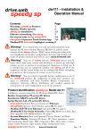
Arctic Modbus Gateway
Configuration Manual
Arctic Modbus Gateway
Configuration Manual
Copyright and Trademark
Copyright © 2004, Viola Systems Ltd. All rights to this manual are owned solely by Viola Systems
Ltd. (referred in this manual as Viola Systems). All rights reserved. No part of the contents of this
manual may be transmitted or reproduced in any form or by any means without the written
permission of Viola Systems.
Ethernet is a trademark of XEROX Corporation. Windows and Internet Explorer are trademarks of
Microsoft Corporation. Netscape is a trademark of Netscape Communications Corporation. Linux is a
Registered Trademark of Linus Torvalds. All other product names used in this manual are the
properties of their respective owners and are acknowledged.
Viola Systems Ltd.
Lemminkäisenkatu 32
FIN-20520 Turku
Finland
Technical
Phone:
Fax:
E-mail:
On-line:
Support
+358 (0)20 1226 226
+358 (0)20 1226 220
[email protected]
http://www.violasystems.com/
Copyright © 2004, Viola Systems Ltd.
Page 2
Arctic Modbus Gateway
Configuration Manual
Disclaimer
Viola Systems reserves the right to change the technical specifications or functions of its products,
or to discontinue the manufacture of any of its products or to discontinue the support of any of its
products, without any written announcement and urges its customers to ensure, that the
information at their disposal is valid.
Viola software and programs are delivered “as is”. The manufacturer does not grant any kind of
warranty including guarantees on suitability and applicability to a certain application. Under no
circumstances is the manufacturer or the developer of a program responsible for any possible
damages caused by the use of a program. The names of the programs as well as all copyrights
relating to the programs are sole property of Viola Systems. Any transfer, licensing to a third party,
leasing, renting, transportation, copying, editing, translating, modifying into another programming
language or reverse engineering for any intent is forbidden without the written consent of Viola
Systems.
Viola Systems has attempted to verify all information in this manual as of the publication date. We
assume no responsibility for any errors that may appear in this guide. Information in this manual
may change without prior notice from Viola Systems.
Copyright © 2004, Viola Systems Ltd.
Page 3
Arctic Modbus Gateway
Configuration Manual
Tableof Contents
1. INTRODUCTION........................................................................................................................5
2. PARAMETERS............................................................................................................................6
2.1. Common parameters.........................................................................................................6
2.1.1. Gateway Status.........................................................................................................6
2.1.2. Gateway Mode...........................................................................................................6
2.1.3. Serial Protocol............................................................................................................6
2.1.4. Network Protocol........................................................................................................7
2.1.5. Slave Response Timeout............................................................................................7
2.1.6. Inter-Frame Timeout..................................................................................................7
2.1.7. Generate Gateway Exceptions...................................................................................7
2.1.8. Pass Gateway Exceptions...........................................................................................7
2.1.9. Serial Port..................................................................................................................8
2.1.10. Serial Speed............................................................................................................8
2.1.11. Serial Data Bits........................................................................................................8
2.1.12. Serial Stop Bits........................................................................................................8
2.1.13. Serial Parity.............................................................................................................8
2.1.14. Serial Flow Control...................................................................................................9
2.1.15. Server TCP/UPD Port................................................................................................9
2.1.16. Maximum Number of Clients....................................................................................9
2.1.17. Connection Idle Timeout..........................................................................................9
2.1.18. Enable Keepalive.....................................................................................................9
2.2. Routes............................................................................................................................10
2.2.1. Route in Use............................................................................................................10
2.2.2. Host.........................................................................................................................10
2.2.3. TCP or UDP Destination Port.....................................................................................10
2.2.4. Filter Slave Address.................................................................................................10
2.2.5. Address to Filter.......................................................................................................11
2.2.6. Connection Idle Timeout..........................................................................................11
2.2.7. Enable TCP Keepalive...............................................................................................11
3. CONFIGURING NETWORK MASTER TO SERIAL SLAVES MODE..................................................12
3.1. Settings – Common parameters......................................................................................13
3.2. Saving Parameters..........................................................................................................14
4. CONFIGURING SERIAL MASTER TO NETWORK SLAVES MODE..................................................15
4.1.Settings – Common Parameters........................................................................................16
4.1.1. Saving Common Parameters....................................................................................17
4.2.Settings – Routes.............................................................................................................18
4.2.1. Saving Routes..........................................................................................................19
4.3. Making Settings Permanent.............................................................................................19
Copyright © 2004, Viola Systems Ltd.
Page 4
Arctic Modbus Gateway
Configuration Manual
1. INTRODUCTION
This Configuration guide is intended only for configuring Modbus on Viola Arctic device. It therefore
presents only Modbus specific functionality. If you need to know more about general Arctic
configuration, please refer to Arctic User's Manual. This User's Manual should be shipped with Arctic
products or it could be obtained by contacting Viola Systems.
The Modbus Gateway is an adapter application enabling conversions between Serial and Network
Modbus protocols. The gateway can operate on two modes; either connecting serial Masters to
Slaves behind the network or connecting network Master to Serial slaves.
The gateway offers following core properties:
•
Supports Modbus RTU and Modbus ASCII serial protocols
•
Supports ModbusTCP, ModbusRTU over TCP, ModbusRTU over UDP, Modbus ASCII over TCP
and Modbus ASCII over UDP network protocols
•
Can generate and filter out gateway exceptions
•
Can route traffic on network based on Modbus addressing enabling intelligent use of
network resources
•
Makes automatic connection management
•
Enables multiple server sessions over network
•
Offers unlimited amount of Masters on serial or Network side
•
Offers 30 routes over network to slaves.
Copyright © 2004, Viola Systems Ltd.
Page 5
Arctic Modbus Gateway
Configuration Manual
2. PARAMETERS
The parameters are divided on two groups:
•
Common parameters
•
Routes.
Common parameters define e.g. the protocols used in serial and network communications, serial
port settings and protocol specific timeouts. Route parameters are only required on Serial Master to
Network Slaves mode defining the IP and Modbus addresses of slaves behind the network.
2.1. Common parameters
The common parameters define general settings and settings for Network Master to Serial Slaves
mode.
2.1.1. Gateway Status
Identifier
Description
Values
Gateway Status
Defines is the Modbus gateway functionality enabled for the serial port
Enabled – Modbus Gateway is enabled
Notes
Disabled – Modbus Gateway is not enabled
Each serial port of Arctic has it’s own Modbus Gateway definitions
2.1.2. Gateway Mode
Identifier
Description
Values
Gateway Mode
Defines are the slaves located on network or serial side
Network Master to Serial Slaves – Slaves are on serial side
Notes
Serial Master to Network Slaves – Slaves are on network side
If slaves are on network side also routes are needed to be defined
2.1.3. Serial Protocol
Identifier
Description
Values
Serial Protocol
Defines the Modbus protocol used on serial communication
Modbus RTU – Serial devices use Modbus RTU protocol
Notes
Modbus ASCII – Serial devices use Modbus ASCII protocol
Modbus RTU is more efficient and should be used whenever possible
Copyright © 2004, Viola Systems Ltd.
Page 6
Arctic Modbus Gateway
Configuration Manual
2.1.4. Network Protocol
Identifier
Description
Values
Network Protocol
Defines the TCP/IP and Modbus protocol used on network communication
Modbus TCP – Modbus TCP protocol over TCP
Modbus RTU over TCP – Modbus RTU protocol over TCP
Modbus RTU over UDP – Modbus RTU protocol over UDP
Modbus ASCII over TCP – Modbus ASCII protocol over TCP
Notes
Modbus ASCII over UDP – Modbus ASCII protocol over UDP
If Viola Systems M2M Gateway is used to tunnel network traffic over SSH
use Modbus RTU over UDP when possible for efficient communication. The
SSH tunnel already contains TCP properties like reliable message delivery.
2.1.5. Slave Response Timeout
Identifier
Description
Values
Notes
Slave response timeout
Defines the time in microseconds (10E-6 seconds) how long Arctic waits the
response from Modbus slave. If the response is not receive Arctic can
generate and return Modbus gateway exception
0 – 90 000 000 microseconds (0 – 90 seconds)
The reply timeout of Modbus Master must be greater than the Gateway
(Arctic) timeout. Otherwise the flow of request-reply communication is
violated. Arctic does not accept a new request before the reply from slave is
received or the reply timeout is elapsed. The delays in network
communication can vary especially in wireless (e.g. GPRS/EDGE/Mobitex)
networks. When the slaves are located on network side use e.g. PING to
estimate the delay packets spend on network.
2.1.6. Inter-Frame Timeout
Identifier
Description
Values
Notes
Inter-frame timeout
Defines the idle time in microseconds (10E-6 seconds) that marks the end
of Modbus frame in serial communication., If value is zero the Gateway uses
standard 4 character time.
0 … 2 000 000 microseconds (0 – 2 seconds)
Use as small value as possible to speed up communication and increase the
value if problems arise. Some PC programs can insert unexpected delays
between serial characters.
2.1.7. Generate Gateway Exceptions
Identifier
Description
Values
Notes
Generate Gateway exceptions
Defines does the Gateway generate and return Modbus Gateway exception
message to Master if no valid reply is not received from slave
Enabled – Generation of Gateway exceptions is enabled
Disabled - Generation of Gateway exceptions is disabled
This functionality is useful for debugging. See also parameter “Pass
Gateway exceptions”.
Copyright © 2004, Viola Systems Ltd.
Page 7
Arctic Modbus Gateway
Configuration Manual
2.1.8. Pass Gateway Exceptions
Identifier
Description
Values
Pass Gateway exceptions
Defines are the Gateway exception replies from slave side passed to
master.
Enabled – Gateway exception replies are passed to Master
Notes
Disabled – Gateway exception replies are filtered away
This functionality is useful for debugging.
2.1.9. Serial Port
Identifier
Description
Values
Notes
Serial Port
Defines the serial port that Gateway uses for Modbus serial communication
Port 1 – Serial port 1 (RS-232 console/application port)
Port 2 – Serial port 2 (RS-232/422/485 application port)
If single serial port or RS-422/485 is required use Port 2. If Port 1 is used the
console switch of Arctic must be on Application position. DIP-switches below
the DB-9 serial connector specify the RS-232/422/485 settings of Port 2.
2.1.10. Serial Speed
Identifier
Description
Values
Notes
Speed
Defines the serial port speed for Modbus communication
300, 1200, 2400, 4800, 9600, 19200, 38400, 57600, 115200 bps
Check the speeds supported by connected Modbus equipment. If special
serial port speed is required please contact Viola Systems.
2.1.11. Serial Data Bits
Identifier
Description
Values
Notes
Serial Data bits
Defines the number of data bits used on Modbus serial communications
5, 6, 7, 8, Auto (8 for Modbus RTU, 7 for Modbus ASCII)
Check the data bits supported by connected Modbus equipment. Generally
Modbus RTU communication uses 8 data bits and Modbus ASCII
communication uses 7 data bits.
2.1.12. Serial Stop Bits
Identifier
Description
Values
Notes
Serial Stop bits
Defines the number of stop bits used on Modbus serial communications
1,2
Copyright © 2004, Viola Systems Ltd.
Page 8
Arctic Modbus Gateway
Configuration Manual
2.1.13. Serial Parity
Identifier
Description
Values
Serial Parity
Defines the parity method used on Modbus serial communication
None – no parity method used
Even – even parity bit generated and inspected
Odd – odd parity bits generated and inspected
Notes
2.1.14. Serial Flow Control
Identifier
Description
Values
Serial Flow control
Defines is the hardware (RTS/CTS) flow control used on Modbus serial
communication
Enabled – RTS/CTS flow control used
Notes
Disabled – RTS/CTS flow control not used
Use of hardware flow control is suggested
2.1.15. Server TCP/UPD Port
Identifier
Description
Values
Notes
Server TCP/UDP port
Defines the TCP or UDP port that Masters can form connections to. Default
Modbus TCP/IP communication port is 502.
1 - 32500
If multiple Modbus Gateways are running on same device (for both serial
ports) the TCP/UDP communication ports must not be same. Use e.g. ports
502 and 504. The network and Arctic firewalls must enable TCP or UDP
communication for that port.
2.1.16. Maximum Number of Clients
Identifier
Description
Values
Notes
Maximum number of clients
Defines how many network masters can be connected to Gateway
simultaneously.
0-20
Generally use value at least 2 when using TCP communication. Otherwise if
the Gateway does not recognize partially closed connection, forming of new
connections is not accepted by Gateway before “Connection idle timeout” is
elapsed.
2.1.17. Connection Idle Timeout
Identifier
Description
Values
Notes
Connection idle timeout
If the connected Master hasn’t sent valid Modbus packets during that
timeout the connection is closed by Arctic and therefore the resources are
available for new connections. This parameter is especially useful when the
network connection is not reliable causing ’hanging’ or partially closed
connections
0 – 32500 seconds
Set this value about two times the polling interval of master
Copyright © 2004, Viola Systems Ltd.
Page 9
Arctic Modbus Gateway
Configuration Manual
2.1.18. Enable Keepalive
Identifier
Description
Values
Enable keepalive
Defines is the connection testing enabled for TCP network communication
Enabled – Testing the TCP connection with Master is enabled
Notes
Disabled – Testing the TCP connection with Master is disabled
The testing is done by sending TCP keepalive packets on certain intervals
2.2. Routes
When the Arctic Modbus Gateway is configured to Serial Master to Network Slaves mode the routes
are needed to be defined for each connected Modbus slave. Gateway can route traffic based on
Modbus addressing therefore enabling more efficient communication where each slave receives
only data addressed to it.
2.2.1. Route in Use
Identifier
Description
Values
Notes
Route in use
Defines is this route entry used to decide to which IP address Modbus
request is sent
Yes – Route information is used
No – Route information is not used
If no route is found for Modbus request is it dropped and Gateway exception
is generated if enabled
2.2.2. Host
Identifier
Description
Values
Notes
Host
Defines the IP address or Host name where packets are routed by that entry
IP address or Host name
If Host names are used the DNS server IP address is required to be defined
on Arctic Network settings. The Network Protocol setting on “Common
parameters” defines the network- and Modbus protocol used on network
communication.
2.2.3. TCP or UDP Destination Port
Identifier
Description
Values
Notes
TCP or UDP destination port
Defines the UDP or TCP destination port where this route entry sends
Modbus requests
0 – 32500 (Modbus default is 502)
The port must be same as used on the network slave device or Gateway
behind network.
Copyright © 2004, Viola Systems Ltd.
Page 10
Arctic Modbus Gateway
Configuration Manual
2.2.4. Filter Slave Address
Identifier
Description
Values
Notes
Filter slave address
Defines is the routing based on Modbus addresses used for that entry. If not
enabled every Modbus request is routed to this entry. If enabled only
Modbus requests having destination address matching the Address list of
entry are routed.
Yes – Route entry checks for Modbus destination address
No – Route entry enables any Modbus destination address
It’s generally good to use Modbus address filtering avoiding unnecessary
network traffic.
2.2.5. Address to Filter
Identifier
Description
Values
Notes
Address to filter
Comma separated list of the Modbus addresses of slaves behind on this
route entry (max. 20 pcs.)
Maximum 20 pcs. of comma (,) separated Modbus destination addresses
The “Filter Slave address” parameter of Route entry needs to be enabled
these addresses to take effect.
2.2.6. Connection Idle Timeout
Identifier
Description
Values
Notes
Connection idle timeout
If there hasn’t been communication on this route during given amount of
seconds the Gateway automatically closes the TCP connection to slave and
therefore frees Slave’s communication resources. This is especially useful
when multiple Masters access same Slave.
0 – 32500 seconds
Set this parameter about two times the polling interval of Master.
2.2.7. Enable TCP Keepalive
Identifier
Description
Values
Enable TCP keepalive
Defines is the connection testing enabled for TCP network communication
Enabled – Testing the TCP connection with Slave is enabled
Notes
Disabled – Testing the TCP connection with Slave is disabled
The testing is done by sending TCP keepalive packets on certain intervals
Copyright © 2004, Viola Systems Ltd.
Page 11
Arctic Modbus Gateway
Configuration Manual
3. CONFIGURING NETWORK MASTER TO SERIAL SLAVES
MODE
When the PLC/RTU slaves supporting serial based Modbus communication are required to be
controlled over TCP/IP networks the Gateway on slave side needs to be configured to Network
Master-Serial Slaves mode.
Fig 3-1. Arctic Modbus Gateway connecting serial slaves to network.
On that mode the Arctic Modbus Gateway acts like network server where Masters (clients) can
connect (the default port being 502) and transmit Modbus requests. The Gateway makes
conversions between network and serial protocols. If the slave does not reply during defined
timeout or if the reply is corrupted the Gateway sends “gateway exception message” back to
Master if the exception generation is enabled. Otherwise the reply is returned. Multiple masters can
connect simultaneously to Gateway, which handles the multiplexing between masters.
NOTE! Each Arctic Modbus Gateway must have a fixed IP address in order the Master to
know where to connect. Many client-use optimized networks (like public GPRS, xDSL)
does not offer fixed IP addresses but allocate them dynamically. This situation can be
solved by using Viola Systems M2M Gateway.
Copyright © 2004, Viola Systems Ltd.
Page 12
Arctic Modbus Gateway
Configuration Manual
3.1. Settings – Common parameters
Only the common parameters are configured. The routes are unused on Network Master to Serial
Slaves mode. The configuration menu is located on Applications - Modbus GW menu of Arctic WEB
configuration.
Fig. 3-2. Example of common parameters for Network Master to Serial Slaves mode
Copyright © 2004, Viola Systems Ltd.
Page 13
Arctic Modbus Gateway
Configuration Manual
Table 3-1. Setting guideline for Network Master to Serial Slaves mode
Parameter
Gateway Status
Gateway Mode
Serial Protocol
Network Protocol
Value
Enabled
Network Master to Serial Slaves
Depends of connected Modbus slave
Depends of Master side
Slave response timeout
Depends of connected Modbus slave
Inter-frame timeout
Modbus RTU protocol has standard
timeout of 4 character time. Use value 0
for default.
Enable or Disable
Generate Gateway
exceptions
Pass Gateway exceptions
Serial Port
Enable or Disable
Select Port 1 or Port 2
Serial Speed
Serial Data Bits
Depends of connected Modbus slave
Depends of connected Modbus slave.
Use of “Auto” selects 8 data bits for
Modbus RTU and 7 data bits for Modbus
ASCII.
Depends of connected Modbus slave.
Depends of connected Modbus slave.
Select None, Even or Odd
Enable if require by slave
Default port for Modbus network
communication is 502
Serial Stop Bits
Serial Parity
Serial HW Handshaking
Server TCP/UDP Port
Max. Number of clients
Connection idle timeout
Enable keepalive
Normally use minimum value 2. If
multiple Masters are allowed to connect
increase the value.
Set about two times the polling interval
of Master. If the polling interval is very
long (over hour) use e.g. polling
interval+200 seconds
Enable if the polling interval or idle
timeout is very long.
Note
Prefer Modbus RTU when possible
If Viola Systems M2M tunneling is
used prefer UDP based Modbus
network messaging
Increase this value if problems on
serial communication
Increase this value if problems on
serial communication.
Enabling Gateway Exceptions can
help system debugging and
testing
If single serial port or RS-422/485
functionality is required use Port 2
If multiple Modbus Gateway
applications are running on same
Arctic the ports must be different
for each Gateway application. Use
e.g. ports 502 and 504.
If the network is wireless or
unreliable increase this value if
problems on connection forming.
3.2. Saving Parameters
When settings are complete press the Apply button, permanently store the parameters by Commit
button and reboot the Arctic by pressing Reboot button. The Arctic is now ready to deliver data
from Network Masters to Serial Slaves.
Copyright © 2004, Viola Systems Ltd.
Page 14
Arctic Modbus Gateway
Configuration Manual
4. CONFIGURING SERIAL MASTER TO NETWORK SLAVES
MODE
When Modbus Master supporting serial based Modbus communication needs to control slaves over
TCP/IP network the Gateway on Master side needs to be configured to Serial Master – Network
Slaves mode.
Fig 4-1. Arctic Modbus Gateway connecting serial Master to network.
On that mode Arctic Modbus Gateway routes serial Modbus packets to network and performs
conversions between serial and network protocols. The routing based on Modbus addressing allows
intelligent use of network resources, which is especially useful for pay-per-use networks like GPRS.
The settings consist of two parts:
•
Common settings
•
Settings for each route.
Copyright © 2004, Viola Systems Ltd.
Page 15
Arctic Modbus Gateway
Configuration Manual
4.1. Settings – Common Parameters
The configuration menu is located on Applications - Modbus GW menu of Arctic WEB configuration.
Fig. 4-2. Example of common parameters for Serial Master to Network Slaves mode
Copyright © 2004, Viola Systems Ltd.
Page 16
Arctic Modbus Gateway
Configuration Manual
Table 4-1. Setting guideline for Network Master to Serial Slaves mode
Parameter
Gateway Status
Gateway Mode
Serial Protocol
Network Protocol
Value
Enabled
Serial Master to Network Slaves
Depends of connected Modbus Master
Depends of Slave devices
Slave response timeout
Depends of connected Modbus slave and
delays of TCP/IP network
Modbus RTU protocol has standard
timeout of 4 character time. Use value 0
for default.
Enable or Disable
Inter-frame timeout
Generate Gateway
exceptions
Pass Gateway exceptions
Serial Port
Enable or Disable
Select Port 1 or Port 2
Serial Speed
Serial Data Bits
Depends of connected Modbus Master
Depends of connected Modbus Master.
Use of “Auto” selects 8 data bits for
Modbus RTU and 7 data bits for Modbus
ASCII.
Depends of connected Modbus Master.
Depends of connected Modbus Master.
Select None, Even or Odd
Enable if require by Master
Default port for Modbus network
communication is 502
Normally use minimum value 2. If
multiple Masters are allowed to connect
increase the value.
Set about two times the polling interval
of Master. If the polling interval is very
long (over hour) use e.g. polling
interval+200 seconds
Enable if the polling interval or idle
timeout is very long.
Serial Stop Bits
Serial Parity
Serial HW Handshaking
Server TCP/UDP Port
Max. Number of clients
Connection idle timeout
Enable keepalive
Note
Prefer Modbus RTU when possible
If Viola Systems M2M tunneling is
used prefer UDP based Modbus
network messaging
Increase this value if problems on
slave communication
Increase this value if problems on
serial communication.
Enabling Gateway Exceptions can
help system debugging and
testing
If single serial port or RS-422/485
functionality is required use Port 2
Value is not used on Serial Master
to Network Slaves mode
Value is not used on Serial Master
to Network Slaves mode
Value is not used on Serial Master
to Network Slaves mode. Each
route entry has it’s own idle
timeout
Value is not used on Serial Master
to Network Slaves mode. Each
route entry has it’s own keepalive
setting.
4.1.1. Saving Common Parameters
Before proceeding to Route configuration save the Common parameters by pressing the Apply
button.
Copyright © 2004, Viola Systems Ltd.
Page 17
Arctic Modbus Gateway
Configuration Manual
4.2. Settings – Routes
The route entries define how Modbus packets are routed on network from Serial Master to Network
Slaves. Up to 30 routes can be specified each having up to 20 slaves. If the routing based on
Modbus addressing is not required or there is more than 20 slaves behind the route the address
filtering for that entry can be disabled.
Fig 4-3. Route summary.
The route entry can be edited by pressing Edit button. The routes can also be disabled or enabled
by pressing following buttons:
Disables the Route entry
Enables the Route Entry.
The active routes do not have strikethrough line.
Pressing the Edit button opens following configuration screen:
Fig 4-4. Route edit.
Copyright © 2004, Viola Systems Ltd.
Page 18
Arctic Modbus Gateway
Configuration Manual
Table 4-2. Setting guidelines for routes
Parameter
Route in use
Value
Enable or Disable
Host
The IP address or Host name of slave
or Gateway behind the route
TCP or UDP destination
port
Filter slave addresses
The TCP or UDP port that slave or
Gateway on slave side is listening
Defines is the routing based on
Modbus addresses used for that entry.
If not enabled every Modbus request is
routed to this entry. If enabled only
Modbus requests having destination
address matching the Address list of
entry are routed.
Comma separated list (max 20 pcs.) of
Modbus slave addresses behind this
route entry.
Set about two times the polling interval
of Master. If the polling interval is very
long (over hour) use e.g. polling
interval+200 seconds
Enable if the polling interval or idle
timeout is very long.
Address to filter
Connection idle timeout
(TCP)
Enable TCP keepalive
Note
Each IP address and TCP/UDP port of
slaves needs to be defined on separate
route entries.
If Host names are used the DNS server IP
address is required to be defined on
Arctic Network settings. The Network
Protocol setting on “Common
parameters” defines the network- and
Modbus protocol used on network
communication.
Default Modbus port is 502
It’s generally good to use routing based
on Modbus addressing in order to avoid
unnecessary network traffic
The “Filter Slave address” parameter of
Route entry needs to be enabled these
addresses to take effect.
4.2.1. Saving Routes
When parameters are configured press the Route Ready button and proceed to next route.
4.3. Making Settings Permanent
When all Routes and Common settings are configured permanently store the parameters by
Commit button and reboot the Arctic Modbus Gateway. The Arctic is now ready to deliver data
from serial Masters to network Slaves.
Copyright © 2004, Viola Systems Ltd.
Page 19