1
WebRelay-QuadTM
User’s Manual
Revision 1.0
February 16, 2006
Covers: XRDI-WRQ-LS & XRDI-WRQ-POE-LS
A division of…
Xytronix Research & Design, Inc.
North Logan, Utah, USA
Revision 1.0
WebRelay-QuadTM Users Manual
Contents
Trademark and Copyright Information
Warranty
Installation Guidelines (Read Before Installing)
Section 1: Introduction
1.1 WebRelay-QuadTM Models Available
1.2 General Layout of the Circuit Board
Section 2: Installation and Setup
2.1 Connection
2.1.1 Power Supply Connection
2.1.2 Network Connection
2.1.3 Relay Connection
2.2 Establishing Communications for Setup
2.2.1 Option 1: Assign a temporary IP address to WebRelay QuadTM
2.2.2 Option 2: Assign a temporary IP address to configuration computer
2.2.3 Open Configuration Web Page Setup
2.3 Web-Based Setup
2.3.1 Main Setup Page
2.3.2 Network Setup Page
2.3.3 Password Setup Page
2.3.4 Relay Setup Pages
Section 3: Operation
3.1 Browser Operation
3.2 XML Operation
Appendix A: Restoring Factory Default Settings
Appendix B: Specifications
Appendix C: Mechanical Information
Appendix D: Open TCP Legal Notice
Xytronix Research & Design, Inc.
page 1
Revision 1.0
WebRelay-QuadTM Users Manual
Trademark and Copyright Information
This document is Copyright ©2005-2006 by Xytronix Research & Design, Inc. All rights reserved.
WebRelay-QuadTM and ControlByWebTM are Trademarks of Xytronix Research & Design, Inc. 2005-2006.
Portions of the software used in WebRelay-QuadTM are open source and appropriate copyright and legal notices are
listed at the end of this manual. All other parts of the software are property of Xytronix Research & Design, Inc.
©2005-2006. The hardware design, schematics, PCB layout, concept, graphics, users manual, etc., are property of
Xytronix Research & Design, Inc. ©2005-2006. WebRelay-QuadTM may not be opened, dis-assembled, copied or
reverse engineered.
No part of this manual may be reproduced or transmitted in any form or by any means, electronic or mechanical,
including photocopying or scanning, for any purpose other than the personal use by the purchaser of this product.
Xytronix Research & Design, Inc., assumes no responsibility for any errors that may appear in this document.
Whereas effort has been made to make the information in this document as useful and accurate as possible, Xytronix
Research & Design, Inc. assumes no responsibility for the application, usefulness, or completeness of the
information contained herein. Under no circumstance will Xytronix Research & Design, Inc. be responsible or liable
for any damages or losses including direct, indirect, special, incidental, or consequential damages or losses arising
from either the use of any information contained within this manual or the use of any products or services referenced
in this manual.
Xytronix Research & Design, Inc. reserves the right to change any product’s features, specifications, documentation,
warranties, fee schedules, and conditions at any time and without notice.
Warranty
This Xytronix Research & Design, Inc. product has a warranty against defects in material and workmanship for a
period of one year from the date of shipment. During the warranty period, Xytronix Research & Design, Inc. will, at
its option, either repair or replace products that prove to be defective. This warranty is extended to the original
purchaser of the equipment only.
For warranty service or repair, the product must be properly packaged, and returned to Xytronix Research & Design,
Inc. The purchaser shall prepay all charges for shipping to Xytronix Research & Design, Inc., and Xytronix
Research & Design, Inc. will pay the shipping charges to return the product to the purchaser as long as the product is
shipped within the United States. If the product is shipped outside of the United States, the purchaser shall pay all
shipping charges, duties, and taxes.
Limitation
The foregoing warranty shall not apply to defects or damage resulting from improper use or misuse, unauthorized
repair, tampering, modification, improper connection, or operation outside the electrical/environmental
specifications for the product. Further, the warranty does not cover Acts of God, such as fire, flood, hurricanes, and
tornadoes. This warranty does not cover damage to property, equipment, direct, indirect, consequential, or incidental
damage (including damage for loss of business profit, business interruption, loss of data, and the like) arising out of
the use or misuse of this product. UNDER NO CIRCUMSTANCES WILL THE LIABILITY OF XYTRONIX
RESEARCH & DESIGN, INC. TO THE PURCHASER OR ANY OTHER PARTY EXCEED THE ORIGINAL
PURCHASE PRICE OF THE PRODUCT, REGARDLESS OF THE FORM OF THE CLAIM. No other warranty is
expressed or implied. Xytronix Research & Design, Inc. specifically disclaims the implied warranties or
merchantability and fitness for a particular purpose. Some jurisdictions may not allow the exclusion of limitation of
liability for consequential or incidental damage.
Xytronix Research & Design, Inc.
page 2
Revision 1.0
WebRelay-QuadTM Users Manual
Installation Guidelines (Read Before Installing)
- Do not exceed contact voltage and/or current ratings.
- This unit must be installed by qualified personnel.
- This unit must not be installed directly outdoors.
- This unit must not be used for medical, life saving purposes, or for any purpose where its failure could cause the
loss of life.
- Proper security precautions should be made before installing WebRelay-QuadTM on the Internet.
Notes about security:
By design, WebRelay-QuadTM is very secure. It does not support terminal or file transfer programs such as telnet,
ftp, ssh, etc. This means that it is not possible for someone to ‘break in’ to WebRelay-QuadTM and access other
devices on your local network. WebRelay-QuadTM does not support remote firmware updates which means that it is
not possible for someone to remotely install malicious software. The simplicity of WebRelay-QuadTM makes it a very
secure device. As with any device to be installed on a network, there are some security precautions that should be
observed. If WebRelay-QuadTM is installed on the Internet, it may be possible for someone to gain access to the
WebRelay-QuadTM control web page and turn the relay on and off. For Internet installations, it is recommended that
passwords be enabled for the control page. Make sure secure passwords are used. Passwords should be at least 8
characters in length and should be a combination of upper case letters, lower case letters, and numbers. Don’t use
passwords that would be easy to guess. For additional security, a firewall may be used to limit access only to
selected IP addresses. Another option may be to set up a Virtual Private Network (VPN) between the network where
WebRelay-QuadTM resides and the client machine (web browser, second WebRelay-QuadTM, etc.).
Xytronix Research & Design, Inc.
page 3
Revision 1.0
WebRelay-QuadTM Users Manual
Section 1: Introduction
is a small circuit board with four electro-mechanical relays and a built in web server. It can be
controlled and/or monitored over any IP network including private networks, IP-based industrial control networks,
and the Internet. Users can operate WebRelay-QuadTM using a web browser or a custom application. Computers or
automation controllers may control and monitor WebRelay-QuadTM without user intervention. This works by sending
text commands over the network and reading XML status pages from WebRelay-QuadTM.
WebRelay-QuadTM
WebRelay-QuadTM has many applications and is only limited by imagination. It works very well as a stand-alone
device that can be controlled using a web browser or as a convenient way to add I/O to a computer. It can be used
in industrial applications to control motors, lights, coils, pumps, valves, etc. It can be used in data centers to control
servers, routers, modems, wireless radios, etc.
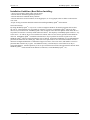
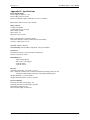
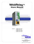
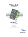
1.1 WebRelay-Quad Models Available
WebRelay-QuadTM is currently available in two models. Both models function identically but are powered by
different means. The two models are described below.
XRDI-WRQ-LS operates from a 5VDC power supply.
XRDI-WRQ-POE-LS can be powered over an Ethernet line (802.3af), or using a 5VDC power supply.
Both models have four low-signal relays that are designed for low power applications. The contacts are designed to
maintain a low resistance and reliably conduct low signals for the life of the relay. If high power switching is
required, the relay contacts can be used to control a high current relay, or the 10Amp WebRelayTM devices are a good
option.
WebRelay Quad
Xytronix Research & Design, Inc.
WebRelay Quad with POE
page 4
Revision 1.0
WebRelay-QuadTM Users Manual
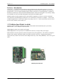
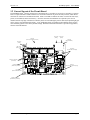
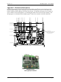
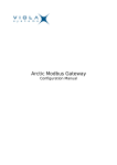
1.2 General Layout of the Circuit Board
The WebRelay-QuadTM board is compact in size measuring only 3.524 inches (8.951cm) by 2.500 inches (6.350cm).
It has a 14-pin removable terminal connector for convenient connection to power and relay contacts, and an RJ-45
connector for connection to an Ethernet network. It has seven LEDs to indicate the status of each of the four relays,
power, network linked, and network activity. All of the connectors and LEDs that are required by the user are
mounted near the top edge of the board so that they can be accessed through a panel if desired (an optional light pipe
can be used to view LEDs through a panel). A tiny pushbutton switch is included on the board that can be used to
reset WebRelay-QuadTM to the factory default settings. Detailed mechanical information is provided in appendix C,
near the end of this manual.
Connector
(Power Input and Relay Contacts)
LED, yellow
(Activity)
LED, green
(Linked)
Connector
(Ethernet Network)
LED, green
(Power)
LEDs, green
(Relay 1-4 ON)
Connectors
(only used with -POE option)
Cutouts for Light Pipes
(not included)
Pushbutton
Switch
Pushbutton Switch
(Reset Factory Defaults)
Connector
(used for factory programming only)
Fuse
(750mA, soldered to board)
Mounting Hole (x4)
(Not electrically connected)
Xytronix Research & Design, Inc.
page 5
Revision 1.0
WebRelay-QuadTM Users Manual
Section 2: Installation and Setup
Installation consists of connecting WebRelay-QuadTM to an IP network, providing power, configuring via a web
browser, and wiring relay contacts to the device(s) that will be controlled.
2.1 Connection
Connection to power and relay contacts is made through the 14-pin connector (provided). The network (and power
on POE units) is connected through the RJ-45 connector on the front of the unit. Pin 1 of the 14-pin connector is the
pin furthest away from the Ethernet connector.
14-pin connector pinout:
Pin
1
Description
+5VDC power supply input. Connect to the positive side of a regulated 5VDC power supply.
The power supply must be able to deliver at least 500mA.
WebRelay-QuadTM units that have the power-over-ethernet option (-POE) do not require a
power supply to be connected to this pin when the unit is connected to an 802.3af compliant
power source.
2
Power supply ground (-) connection.
3
Relay 1 Common Contact
4
Relay 1 Normally Closed Contact
5
Relay 1 Normally Open Contact
6
Relay 2 Common Contact
7
Relay 2 Normally Closed Contact
8
Relay 2 Normally Open Contact
9
Relay 3 Common Contact
10
Relay 3 Normally Closed Contact
11
Relay 3 Normally Open Contact
12
Relay 4 Common Contact
13
Relay 4 Normally Closed Contact
14
Relay 4 Normally Open Contact
2.1.1 Power Supply Connection
The WebRelay-QuadTM unit requires power for its internal web server circuitry. A 5VDC power supply
must be connected to WebRelay-QuadTM through the relay socket connector. Alternatively, WebRelayQuadTM units with the Power Over Ethernet option may be powered through the Ethernet connection instead
of using an external power supply.
Multiple WebRelay-QuadTM units may be connected to a single power supply by connecting their power
supply inputs to a power supply in parallel. The power supply must be rated for at least 400mA for each
WebRelay-QuadTM connected.
Xytronix Research & Design, Inc.
page 6
Revision 1.0
WebRelay-QuadTM Users Manual
WebRelay-QuadTM units with the Power Over Ethernet option may be connected to an 802.3af compliant
Ethernet port instead of connecting a 5V power supply. This eliminates the need for a 5VDC power supply
because WebRelay-QuadTM is powered through the Ethernet port. The power in the Ethernet port comes
from an 802.3af compliant hub, switch, or power injector which may be located in a utility closet which
could be a distance away from WebRelay-QuadTM. This option is very useful for WebRelay-QuadTM
installations where power is not available for a 5V power supply.
2.1.2 Network Connection
Connect the Ethernet port to a 10 Base T or 10/100 Base T Ethernet connection. This typically connects to
an Ethernet hub, switch, or router. For configuration, WebRelay-QuadTM may be connected directly to the
Ethernet port on a computer using a “crossover” cable. Otherwise for connection through a hub or router, a
standard “straight-thru” cable should be used.
2.1.3 Relay Connection
The relay contacts internally connect directly to the 14-pin connector. No internal fuse is provided. The
relay contacts are rated at 1 Amp (24VDC). If the power source connected to the relay contacts can deliver
more than 1 Amp, an external fuse or circuit breaker should be used. Direct access to Common, Normally
Open, and Normally Closed contacts are provided.
2.2 Establishing Communications for Setup
WebRelay-QuadTM is set up using a web browser. The first task is to establish communications between a computer
and the WebRelay-QuadTM device so that the browser-based configuration can begin. To do this, the computer and
WebRelay-QuadTM must be physically connected to the same network and both must have IP addresses on the same
network. There are two ways to set up the computer and WebRelay-QuadTM so that they are on the same network.
The first way (Option 1) is to change the IP address of WebRelay-QuadTM to an address that is on the same network
as the computer. The second way (Option 2) is to change the IP address of the computer to an address that is on the
same network that WebRelay-QuadTM is set to by default.
2.2.1 Option 1: Assign a temporary IP address to WebRelay-QuadTM
This option is used to TEMPORARILY assign an IP address to WebRelay-QuadTM without the need to
change the IP address of the configuration computer. It is the recommended method for establishing initial
communications. Note that WebRelay-QuadTM will only use this IP address as long as power is maintained.
Once power is lost and restored, WebRelay-QuadTM will use the IP address assigned in the setup page and
not the temporary address assigned here. This means that once communications are established, the desired
IP address should be entered into the network setup page using the browser.
To assign the temporary IP address...
1.
Make sure WebRelay-QuadTM and the configuration computer are connected to the same physical
network. This will not work through routers or gateways.
2.
Assign the address as follows...
Windows:
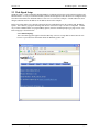
Open a Command Prompt (on Windows XP, select START, then RUN, then type “cmd”).
Type...
arp -s {new IP address} {serial number of WebRelay-QuadTM }
Note:
IP address format is: xxx.xxx.xxx.xxx
Serial number format is: ss-ss-ss-ss-ss-ss
For example, to set a WebRelay-QuadTM device (with serial number 00-0C-C8-01-00-01 )
to 10.10.10.40 the following command would be used.
arp -s 10.10.10.40 00-0c-c8-01-00-01
Xytronix Research & Design, Inc.
page 7
Revision 1.0
WebRelay-QuadTM Users Manual
Next, type...
ping -l 102 {new IP address}
For example, if the new IP address is 10.10.10.40, the following command would be
used.
ping -l 102 10.10.10.40
Linux/Unix:
Open a terminal, change to root user (su -, then enter root password).
Type...
arp -s {new IP address} {serial number of WebRelay-QuadTM }
Note:
IP address format is: xxx.xxx.xxx.xxx
Serial number format is: ss:ss:ss:ss:ss:ss
For example, to set a WebRelay-QuadTM device (with serial number 00-0C-C8-01-00-01 )
to 10.10.10.40 the following command would be used.
arp -s 10.10.10.40 00:0c:c8:01:00:01
Next, type...
ping -s 102 {new IP address}
For example, if the new IP address is 10.10.10.40, the following command would be
used.
ping -s 102 10.10.10.40
Mac OS X
Open a terminal,
Note that the terminal is in the “Utilities” directory which is in “Applications” directory.
type
sudo arp -s {new IP address} {serial number of WebRelay-QuadTM }
Note:
Administrator password is required.
IP address format is: xxx.xxx.xxx.xxx
Serial number format is: ss:ss:ss:ss:ss:ss
For example, to set a WebRelay-QuadTM device (with serial number 00-0C-C8-01-00-01 )
to 10.10.10.40 the following command would be used.
sudo arp -s 10.10.10.40 00:0c:c8:01:00:01
Next, type...
ping -s 102 {new IP address}
For example, if the new IP address is 10.10.10.40, the following command would be
used.
ping -s 102 10.10.10.40
Xytronix Research & Design, Inc.
page 8
Revision 1.0
WebRelay-QuadTM Users Manual
2.2.2 Option 2: Assign a temporary IP address to configuration computer
If the first option above is not used, you can use this option to communicate with WebRelay-QuadTM . By
default, WebRelay-QuadTM comes from the factory with an IP address of 192.168.1.2. Communications
with WebRelay-QuadTM may be established by assigning an IP address to the configuration computer that is
on the same network as WebRelay-QuadTM (for example the configuration computer could be assigned to
192.168.1.5) .
Instructions for changing the IP address of the computer that will be used for WebRelay-QuadTM
configuration are given here. Note that these instructions are specifically for computers with the Windows
XP operating system. For setup using other operating systems, refer to the appropriate users manual.
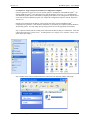
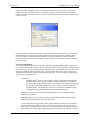
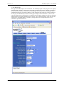
Step 1: Open the control panel by clicking on the start menu and then clicking on Control Panel. (Note that
control panel shown is in “Classic View”. If control panel is in “Category View” select the “Classic View”
option before proceeding.)
Step 2: Double click on the icon labeled Network Connections. The following window will pop up.
Xytronix Research & Design, Inc.
page 9
Revision 1.0
WebRelay-QuadTM Users Manual
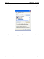
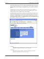
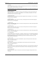
Step 3: Right click on the icon labeled Local Area Connection. Another menu will appear. Select the option
at the bottom of the menu labeled Properties. The Local Area Connection Properties window will appear.
Step 4: On the Local Area Connection Properties page scroll down to Internet Protocol (TCP/IP), select it,
and then click the button labeled properties.
Xytronix Research & Design, Inc.
page 10
Revision 1.0
WebRelay-QuadTM Users Manual
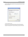
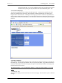
Step 5: Before making any changes to the network settings, write down the current settings so that they can
be restored once WebRelay-QuadTM is configured. Next, select the radio button labeled “Use the following
IP address,” and type in the IP address 192.168.1.50. Type in a subnet mask of 255.255.255.0. Leave the
default gateway field blank.
2.2.3 Open Configuration Web Page
Once the network is set up, open the configuration setup page by typing the following URL into the
browser: http://192.168.1.2/setup.html (note that if option 1 above was used for initial configuration,
replace the IP address given here with the newly assigned IP address). A password is required to change
any parameters. The default password is ‘webrelay’ (do not include quotes, password is case sensitive).
Xytronix Research & Design, Inc.
page 11
Revision 1.0
WebRelay-QuadTM Users Manual
2.3 Web-Based Setup
WebRelay-QuadTM is fully configurable through HTML 4.0 compliant web browsers such as Internet Explorer and
Mozilla Firefox. It’s easy to use tab based menu system has been designed to allow the unit to be configured easily.
Note that in this manual, the default IP address of 192.168.1.2 is used in all examples. If the IP address has been
changed, substitute the new IP address for the address shown in the examples.
Before proceeding, make sure a network connection has been established between the computer and WebRelayQuadTM. This is done by typing the following URL into the web browser: http://192.168.1.2/setup.html. Another
way to check communications is to ping WebRelay-QuadTM (from the command prompt (type ping 192.168.1.2)).
Each setup page is described below.
2.3.1 Main Setup Page
This is the initial page that appears when the URL http://192.168.1.2/setup.html is entered into the web
browser. It provides basic information about the WebRelay-QuadTM unit.
Xytronix Research & Design, Inc.
page 12
Revision 1.0
WebRelay-QuadTM Users Manual
Navigating between setup pages is done by clicking on the tabs at the top of the page. All setup pages
require a password. The default password is ‘webrelay’ (no quotes, all lower case) and no username is
required. Once the password is entered, it will not be required again unless the password is changed or the
browser is closed.
Each setup page has a “Submit” button and a “Reset” button at the bottom of the page. After entering the
desired parameters into each page, the “Submit” button must be pressed before any parameters will be
saved. If a mistake is made in entering the parameters, the “Reset” button may be used to restore all
parameters on the page to their current settings. The “Reset” button is only effective before the “Submit”
button is pressed.
2.3.2 Network Setup Page
The network parameters are changed on this page. Note that if multiple WebRelay-QuadTM units are used
on the same network, install one unit at a time and set the IP address of each unit before connecting the next
unit to the network. This avoids having multiple WebRelay-QuadTM units installed on the network with the
same factory default IP address at the same time. Also note that the unit must be power-cycled (power
disconnected, then reconnected) before network settings take effect. No other setup page requires powercycling for the settings take effect.
1. IP Address:
WebRelay-QuadTM requires a static IP address. This is a unique address that identifies
WebRelay-QuadTM on the network. Dynamic IP address assignment is not supported.
The lack of dynamic IP addressing support is intentional because a dynamically changing
the IP address would make it difficult for a client to access the web server built into
WebRelay-QuadTM. The IP address is specific to the network where WebRelay-QuadTM
will be installed, and must be obtained from the network administrator.
This guide is not meant to be a tutorial on IP addressing, however a few comments about IP
addressing are given here.
If WebRelay-QuadTM will be used over the Internet, the IP address must be a routable address
assigned by the upstream Internet Service Provider (ISP).
In cases where the ISP only provides a single routable IP address for the entire network (this is
typical with ISPs such as cable providers), a proxy server (or gateway router) may be used. A
proxy server allows multiple devices to connect to the Internet using a single routable IP address.
Many small routers from LinkSys, Dlink, and Netgear perform proxy server functions. If a proxy
Xytronix Research & Design, Inc.
page 13
Revision 1.0
WebRelay-QuadTM Users Manual
server is used, WebRelay-QuadTM will not be accessible from the Internet until the proxy server is
properly configured (forward proper port to WebRelay-QuadTM). This information is mentioned
for convenience but details of setting up a configuration such as this is beyond the scope of this
manual.
If WebRelay-QuadTM is used on a private network only and is NOT used over the Internet, a
routable IP address is not necessary. This may be the case when WebRelay-QuadTM is used to
control (or monitor) a device in another room or a nearby building.
If WebRelay-QuadTM will be installed on a simple, private network that does not connect to the
Internet, the default IP address may be used as long as no other device on the network uses the
same address. If multiple WebRelay-QuadTM units are installed on the same network, each unit
must have its own unique IP address. For example, WebRelay-QuadTM comes from the factory
with a default IP address of 192.168.1.2. If multiple units are used, change the IP address for each
unit (192.168.1.3, 192.168.1.4, 192.168.1.5 etc.).
2. Netmask:
This specifies the size of the local network. This must be obtained from the network
administrator. By default, the netmask is set to 255.255.255.0.
3. Broadcast:
This specifies the broadcast address. This must be obtained from the network
administrator. By default, this is set to 192.168.1.255.
Xytronix Research & Design, Inc.
page 14
Revision 1.0
WebRelay-QuadTM Users Manual
4. Gateway:
This specifies the IP address of the gateway router. This must be obtained from the
network administrator. By default, this is set to 192.168.1.1. If no gateway is used, this
can be set to 0.0.0.0 which will prevent WebRelay-QuadTM from looking for a gateway.
5. TCP Port:
This specifies the TCP port used for communications with WebRelay-QuadTM. By
default, the port is set to 80 which is the standard http port. It is recommended that the
port not be changed without an understanding of TCP/IP and ports.
Changing the port can be useful for accessing multiple WebRelay-QuadTM devices which
are installed behind a gateway router on a private network that uses non-routable IP
addresses (192.168.x.x, 10.x.x.x, and 172.16.x.x through 172.31.x.x are non-routable or
private IP addresses). In this case, each WebRelay-QuadTM unit would be assigned a
different port (for example 8000, 8001, 8002, etc). The gateway router would be set up
to forward all traffic for each of the assigned ports to the IP address of the WebRelayQuadTM unit which uses that port. The WebRelay-QuadTM units could then be accessed
from outside the private network by entering the IP address of the gateway and the port
for the desired WebRelay-QuadTM unit. Note that whenever any port is assigned other
than port 80, all communications with that WebRelay-QuadTM device must include the
port. For example, if WebRelay-QuadTM is assigned port 8000, access to the setup page
would require the following URL to be entered; http://192.168.1.2:8000/setup.html.
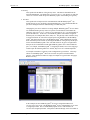
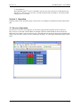
An example screenshot of a gateway router configuration is given below. This setup
allows five WebRelay-QuadTM units to be accessed on a private network behind a
gateway. Note that this screenshot is simply an example of a typical router setup page.
Routers will vary.
In the example, the five WebRelay-QuadTM devices are assigned IP addresses of
10.10.10.41 to 10.10.10.45. The WebRelay-QuadTM device with IP address 10.10.10.41
is assigned port 8000. The second WebRelay-QuadTM device with IP address of
10.10.10.42 is assigned port 8001. This pattern continues through 10.10.10.45 which is
Xytronix Research & Design, Inc.
page 15
Revision 1.0
WebRelay-QuadTM Users Manual
assigned the port 8004. To access the WebRelay-QuadTM units from the Internet, enter the
IP address of the gateway plus the port number of the desired WebRelay-QuadTM unit.
2.3.3 Password Setup Page
The password setup page is used to change and enable passwords. A password is required for the setup
pages but is optional for the control page. The password is enabled or disabled for the control page by
using the Yes or No radio buttons. Enabling the control page password also enables the requirement for a
password when reading/writing XML pages. Note that when the password is changed, the password may be
displayed in the browser’s history in clear text. It is advisable to clear the browsers history after setting the
password.
2.3.4 Relay Setup Pages
These pages are used to set up the function of each of the four relays, and how each relay is represented on
the control page. All four pages are identical, with the exception of the Relay 1 page which also includes a
field for the main header text on the control page, the option to automatically refresh the control page, and
the time duration for auto refresh.
The following settings (1-3) are only included on the Relay 1 setup page and not on Relay 2,3 or 4 setup
pages.
1. Main Header Text:
This text will be displayed in the main header area of the control page. This field can be up to 25 characters
in length.
Xytronix Research & Design, Inc.
page 16
Revision 1.0
WebRelay-QuadTM Users Manual
2. Auto Refresh Page:
Web pages traditionally display static information. The WebRelay-QuadTM control page, however, displays
information that is dynamic. Each time the control page is loaded to the browser, it displays a snapshot of
the current status of the unit. If the state of the unit changes, the information on the control page will be
outdated unless the page is re-loaded. Whenever a user changes the state of the relay via the web browser,
the web page will automatically reload the control page to display current information. If, however, the
relay state changes due to a change due to a command sent from another machine, the relay state will not be
updated and the control page information will be obsolete. The ‘Auto Refresh Page’ option will cause the
control page to continually update its contents by setting a timer in the web page that causes it to be
reloaded at a specified time interval.
Xytronix Research & Design, Inc.
page 17
Revision 1.0
WebRelay-QuadTM Users Manual
3. Duration:
If the ‘Auto Refresh Page’ option is set to Yes, this field specifies the time interval in seconds that the page
will be refreshed. It can be set from 1 to 32 seconds.
The following settings (4-15) are included on all four relay setup pages. The settings correspond only to the
relay associated with that page.
4. Relay Description:
This text is used to describe the function of the relay on the control page. This text will not appear if the
‘Display Relay Status’ is set to No, the ‘On/Off Buttons’ is set to 0, and the ‘Pulse Button’ is set to No.
This field can be up to 20 characters in length.
5. Display Relay Status:
When this option is set to Yes, the relay status will be displayed on the control page. If it is set to No, the
relay status will not be displayed.
6. Status ON Color:
When the ‘Display Relay Status’ option is set to Yes, this field specifies the color that will be displayed
when the relay is on (coil energized).
7. Status ON Text:
When the ‘Display Relay Status’ option is set to Yes, this field specifies the text that will be displayed when
the relay is on (coil energized).
8. Status OFF Color:
When the ‘Display Relay Status’ option is set to Yes, this field specifies the color that will be displayed
when the relay is off (coil not energized).
9. Status OFF Text:
When the ‘Display Relay Status’ option is set to Yes, this field specifies the text that will be displayed when
the relay is off (coil not energized).
10. ON/OFF Buttons:
This option allows the user to specify 0, 1, or 2 buttons to turn the relay on or off. Zero buttons disables the
users ability to turn the relay on and off (a pulse button may still be included... see below). One button may
be used to toggle the relay on and off. Two buttons gives the user one button to turn the relay on and
another button to turn the relay off.
11. Button 1 Label:
When 1 or 2 buttons is selected in the ‘ON/OFF Buttons’ option, this field specifies the text that will be
displayed in pushbutton number 1.
12. Button 2 Label:
When 2 buttons is selected in the ‘ON/OFF Buttons’ option, this field specifies the text that will be
displayed in pushbutton number 2.
13. Pulse Button:
This option allows the user to include a pulse button to control the relay. If the pulse button is included, the
relay will pulse for the time specified in the ‘Pulse Duration’ field in the ‘Relay/Input’ page each time the
button is pressed.
14. Pulse Button Label:
When the ‘Pulse Button’ option is set to Yes, the text entered here will appear in the pulse button on the
control page.
Xytronix Research & Design, Inc.
page 18
Revision 1.0
WebRelay-QuadTM Users Manual
15. Pulse Duration:
When WebRelay-QuadTM receives a command to pulse the relay, this is the time in seconds that the relay
will pulse on. This time can be set from 0.1 seconds to 6000 seconds (100 minutes). The factory default
setting for this is 1.5 seconds.
Section 3: Operation
WebRelay-QuadTM can be operated by using a web browser or by sending text commands to an XML status/control
page.
3.1 Browser Operation
Once the unit is set up, the control page may be accessed by typing the following URL into the web browser:
http://192.168.1.2 (Note that if the IP address was changed, replace the default IP address shown with the new
address that was assigned. Note also that if any port is used other than port 80, the port must also be included in the
request: http://192.168.1.2:8000 ) The new control page will appear. A control page with default settings is shown
below.
Xytronix Research & Design, Inc.
page 19
Revision 1.0
WebRelay-QuadTM Users Manual
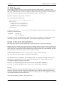
3.2 XML Operation
Custom computer applications may be created to monitor and control WebRelay-QuadTM without using a web
browser. Monitoring the state of the relays is done by sending a request to port 80 (or port specified in setup) for the
XML page. Control of the relay is done by sending GET requests to the same page on port 80 (or port specified in
setup). This can be demonstrated by entering commands into the URL line of a web browser.
Request the current state: http://192.168.1.2/state.xml
This will return the following XML page.:
<?xml version="1.0" encoding="utf-8" ?>
- <datavalues>
<relay1state>0</relay1state>
<relay2state>1</relay2state>
<relay3state>1</relay3state>
<relay4state>1</relay4state>
</datavalues>
The tags <relay1state>... <relay4state> indicate the current state of each of the four relays. Values
for the tags are described below.
<relayXstate>
0=off(coil off)
1=on (coil energized)
Commands can be sent to WebRelay-QuadTM which control the relays. Commands are sent using variables called
relay1State, relay2State, relay3State and relay4State. Two examples of using relayState are given here.
Turn relay1 ‘off’: http://192.168.1.2/state.xml?relay1State=0
Turn relay1 ‘on’: http://192.168.1.2/state.xml?relay1State=1
Pulse relay1: http://192.168.1.2/state.xml?relay1State=2 (note that pulse time is specified in setup pages).
Multiple relays can be changed with a single command by submitting multiple relayXState variables separated by an
ampersand symbol (&). All four relayXState variables can be included, or only a subset. The relayXState variables
can be in any order. Relays that are already in the desired state will not be affected by on/off commands. Note that
pulse commands will reset the pulse timer each time a command is received.
The following line illustrates how to turn ‘on’ relay 1, turn ‘on’ relay 2, and turn ‘off’ relay 4.
http://192.168.1.2/state.xml?relay1State=1&relay4State=0&relay2State=1
Note that when the above commands are sent to WebRelay-QuadTM, its current state is returned in the form of an
XML page. The commands can also be sent without having WebRelay-QuadTM return the XML page. This is
accomplished by adding the noReply field as follows.
Turn relay3 ‘on’ without returning state: http://192.168.1.2/state.xml?relay3State=1&noReply=1
Turn relay3 ‘off’ without returning state: http://192.168.1.2/state.xml?relay3State=0&noReply=1
Password :
If the control password is enabled in the WebRelay-QuadTM unit and the XML page is requested through a browser,
the browser will prompt the user for the password. If the XML request is sent from another application and not a
browser, the html request will need to contain the password encoded using the base 64 encoding scheme. The html
request header without the password looks like this:
GET /state.xml?noReply=1 HTTP/1.1 (Ends with two \r\n)
Xytronix Research & Design, Inc.
page 20
Revision 1.0
WebRelay-QuadTM Users Manual
The html request header with the password looks like this:
GET /state.xml?relay2State=1&noReply=1 HTTP/1.1
Authorization: Basic bm9uZTp3ZWJyZWxheQ== (Ends with two \r\n)
where bm9uZTp3ZWJyZWxheQ== is the base 64 encoded version of the username and password
none:webrelay
A utility is provided at http://www.ControlByWeb.com/encoder that can be used to encode the password. The utility
is used by simply typing the desired password into the website and pressing encode.
Appendix A: Restoring Factory Default Settings
In the event that the IP address or passwords are forgotten, WebRelay-QuadTM may be restored to its original factory
default settings. To do this, first remove the power from the unit. For non-POE (Power Over Ethernet) units, this
may be accomplished by disconnecting the 14-pin connector. For POE units, simply disconnect the network line.
Next, press the small button that is located on the side of the board. When the button is pressed, a tactile feel can be
detected. While holding the button down, apply power and wait for about 10 seconds. After about 10 seconds,
release the button. Now all settings will be back to the original factory defaults.
Xytronix Research & Design, Inc.
page 21
Revision 1.0
WebRelay-QuadTM Users Manual
Appendix B: Specifications
Power Requirements:
Power Supply Voltage: 5V ± 5%
Power Supply Current: 350mA
Power Over Ethernet Option: POE Class 2 (3.84 to 6.49 Watt)
I/O: 4 Relays (Direct access to dry contacts)
Relay Contacts:
Contact Form: SPDT
Contact Material: Ag (Au clad)
Max Voltage: 24VDC
Max Current: 1A
Min Load: 1mA @ 5VDC
Relay Control Options: ON/OFF or Pulsed
Pulse Timer Duration: 100ms to 6000 Seconds (100 minutes)
Accuracy of pulse timer: ±0.1%
Network: 10Base-T Ethernet
Network Setup: static IP address assignment, TCP port selectable
Connectors:
Power/Relay Contacts: 14-pin removable terminal strip
Network: 8-pin RJ-45 socket
LED Indicators: 7
-Input voltage applied
-Relay coils (1-4) engaged
-Network linked
-Network activity
Physical:
Operating Temperature: 32°-158°F ( 0°-70°C)
Size: 3.524in (89.510mm) wide X 2.600in (66.040mm) (including connectors) tall
X 0.660in(16.8mm) high (0.950in (24.1mm) high with POE option)
Weight (Standard): 1.7oz (48.2 grams)
Weight (with POE option): 2.3oz (65.2 grams)
Password Settings:
Password protection on setup page: Yes
Password protection on control page: Optional
Password Encoding: Base 64
Max password length: 10 characters
Xytronix Research & Design, Inc.
page 22
Revision 1.0
WebRelay-QuadTM Users Manual
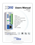
Appendix C: Mechanical Information
The following illustration shows mechanical details for the WebRelay-QuadTM board. Note that when accessing
WebRelay-QuadTM through a panel, a light pipe (Lumex LPF-C07130S) should be used to view the LEDs. The
board is designed so that the light pipes will easily snap into place. The light pipe is designed for seven LEDs, but
only five LEDs are used for this application. The unused light conduits can be cut off for proper mounting. Note
that light pipes are not included with the WebRelay-QuadTM board but are available at electronics distributors.
X=3.364 (85.446mm)
X=3.340 (84.836mm)
X=2.690 (68.326mm)
X=2.493 (63.322mm)
X=1.840 (46.736mm)
X=1.700 (43.180mm)
X=1.100 (27.940mm)
X=0.900 (22.860mm)
X=0.700 (17.780mm)
X=0.360 (9.144mm)
X=0.337 (8.560mm)
X=0.500 (12.700mm)
X=0.160 (4.064mm)
Y=2.600 (66.040mm)
Y=2.500 (63.500mm)
Y=2.340 (59.436mm)
Y=1.805 (45.847mm)
Mounting Holes (4)
SIZE: 0.115" (2.921mm) diameter hole,
0.285" (7.239mm) diameter pad
Not connected to Ground.
Y=1.537 (39.040mm)
2.500 in (6.350 cm)
Y=1.125 (28.575mm)
Pushbutton
Switch
Y=0.160 (4.064mm)
Y=0
3.524 in (8.951 cm)
X=0
X=3.524
WebRelay Quad
with Light Pipes Installed
Xytronix Research & Design, Inc.
page 23
Revision 1.0
WebRelay-QuadTM Users Manual
Appendix D: Open TCP Legal Notice
Portions of the software used in WebRelay-QuadTM are open source. The appropriate notices are listed below. All
other parts of the software are property of Xytronix Research & Design, Inc. ©2005-2006.
Copyright (c) 2000-2002 Viola Systems Ltd.
All rights reserved.
Redistribution and use in source and binary forms, with or without
modification, are permitted provided that the following conditions
are met:
1. Redistributions of source code must retain the above copyright
notice, this list of conditions and the following disclaimer.
2. Redistributions in binary form must reproduce the above copyright
notice, this list of conditions and the following disclaimer in the
documentation and/or other materials provided with the distribution.
3. The end-user documentation included with the redistribution, if
any, must include the following acknowledgment:
"This product includes software developed by Viola
Systems (http://www.violasystems.com/)."
Alternately, this acknowledgment may appear in the software itself,
if and wherever such third-party acknowledgments normally appear.
4. The names "OpenTCP" and "Viola Systems" must not be used to
endorse or promote products derived from this software without prior
written permission. For written permission, please contact
[email protected].
5. Products derived from this software may not be called "OpenTCP",
nor may "OpenTCP" appear in their name, without prior written
permission of the Viola Systems Ltd.
THIS SOFTWARE IS PROVIDED "AS IS" AND ANY EXPRESSED OR IMPLIED
WARRANTIES, INCLUDING, BUT NOT LIMITED TO, THE IMPLIED WARRANTIES OF
MERCHANTABILITY AND FITNESS FOR A PARTICULAR PURPOSE ARE DISCLAIMED.
IN NO EVENT SHALL VIOLA SYSTEMS LTD. OR ITS CONTRIBUTORS BE LIABLE
FOR ANY DIRECT, INDIRECT, INCIDENTAL, SPECIAL, EXEMPLARY, OR
CONSEQUENTIAL DAMAGES (INCLUDING, BUT NOT LIMITED TO, PROCUREMENT OF
SUBSTITUTE GOODS OR SERVICES; LOSS OF USE, DATA, OR PROFITS; OR
BUSINESS INTERRUPTION) HOWEVER CAUSED AND ON ANY THEORY OF LIABILITY,
WHETHER IN CONTRACT, STRICT LIABILITY, OR TORT (INCLUDING NEGLIGENCE
OR OTHERWISE) ARISING IN ANY WAY OUT OF THE USE OF THIS SOFTWARE,
EVEN IF ADVISED OF THE POSSIBILITY OF SUCH DAMAGE.
====================================================================
OpenTCP is the unified open source TCP/IP stack available on a series
of 8/16-bit microcontrollers, please see <http://www.opentcp.org>.
For more information on how to network-enable your devices, or how to
obtain commercial technical support for OpenTCP, please see
<http://www.violasystems.com/>.
Xytronix Research & Design, Inc.
page 24