1
USOO565 1260A
United States Patent [191
[11]
Patent Number:
Goto et al.
[45]
Date of Patent:
[54] CONTROL APPARATUS AND METHOD FOR
ACTUATING AN ELECTRICALLY DRIVEN
COMPRESSOR USED IN AN AIR
CONDITIONING SYSTEM OF AN
AUTOMOTIVE VEHICLE
[21] Appl. N0.: 605,272
Feb. 6, 1996
Foreign Application Priority Data
[JP]
Japan .................................. .. 7-021894
[51]
Int. Cl.6 .................................................... .. F25B 49/02
[52]
US. Cl. ........................ .. 62/126; 62/2284; 62/2592;
[58]
Field of Search ............................ .. 62/126, 125, 127.
165/804
62/129, 259.2, 244. 208, 209, 161, 228.1,
228.4, 228.5, 230; 165/802, 80.3, 80.4.
104.33; 257/721, 722, 714; 361/690, 694,
695, 720, 722, 699, 717
[56]
References Cited
U.S. PATENT DOCUMENTS
4,720,981
l/l996 Carter ............................... .. 165/80.3X
5,493,868
2/1996
et a1. .......................... .. 62/129
ABSTRACT
A micro computer 6 reads a manual switch signal Sm from
an operating section 15, and sets a target output W0 of an
electrically driven compressor 11 based on the manual‘
switch signal Sm. A temperature sensor 20 detects a tem
perature Ts of a designated component in the compressor
Ltd., Japan
Feb. 9, 1995
5,481,433
Primary Examiner-Harry B. Tanner
[57]
[73] Assignee: Matsushita Electric Industrial Co.,
[30]
Jul. 29, 1997
Attorney, Agent, or Firm-Rossi & Associates
[75] Inventors: Naomi Goto. Shiga-ken; Makoto
Yoshida, Kusatsu, both of Japan
[22] Filed:
5,651,260
control system. Micro computer 6 judges whether the
detected temperature Ts is larger than a predetermined upper
limit Ta, and generates an output command W equalized to
the target output W0 when the temperature Ts is within a
predetermined allowable range. On the other hand, when the
detected temperature Ts is higher than the upper limit Ta,
micro computer 6 sets a modi?ed output W1 smaller than
target output W0 by a predetermined correction value AW
(W1=W0—AW>0), and adjusts the output command W to the
modi?ed output W1. Then, the compressor 11 is actuated
based on thus obtained output command W.
_
1/1988 Helt et a1. ........................ .. 62/2284 X
14 Claims, 13 Drawing Sheets
SMALL<—>LARGE
OFF
U
US. Patent
Jul. 29, 1997
Sheet 1 of 13
5,651,260
_|to
w
T
US. Patent
Jul. 29, 1997
5,651,260
Sheet 2 0f 13
FIG. 2A
FIG. 2B
OUTPUT F’,
UPPER L|MIT/»"'
COPNSUMWTEIR
TINEMPR
OUTPUT G
B
POWER CONSUMPTION
OUTPUT
FIG. 20
FIG. 2C
\OUTPUT J
OUTPUT H
UPPER LIMIT /'
‘\
,
l
/
I
/
I
UPPER LIMIT
\
\
I
TINEMPR
A
TINEMPR
\
\
OUTPUT K‘ P \
’ ' OUTPUT 1
E
OUTER TEMP
D
COOLING ABILITY
US. Patent
Jul. 29, 1997
H6. 3
Sheet 3 0f 13
5,651,260
115
1
9
N4
FIG. 5
SENSOR
TEMP
4k
Tb
/
Ta
TIME
COMPRESSOR
OUTPUT
TIME
U.S. Patent
Jul. 29, 1997
Sheet 4 0f 13
5,651,260
H6. 4
READ MANUAL Sw
J31
SIGNAL Sm
S2
SIII OFF 9
N
Y
N83
END
SET TARGET OUTPUT IIIO
>
N84
DETEcT SENSOR TEMP Ts
,
JVSS
STOP COMPRESSOR
III: 0
END
V
N88
DRIvE COMPRESSOR BY
TARGET OUTPUT
w=IIIO
SET MODIFIED
OUTPUT IIII
W1=W0—AW
N810
DRIvE COMPRESSOR BY
REDUCED OUTPUT
III: III
US. Patent
Jul. 29, 1997
Sheet 5 0f 13
5,651,260
FIG. 6
—-—CASE1:AW=kl-(Ts—-Ta)
SENSOR
—-- CASE 2 = nw=k1- (Ts—Ta) +
TEMP
k2-MTS- Ta)/At
A
Tb - ----------------- -
Ta
I
OUTPUT
COMPRESSOR
----------------------------- -
n
TIME
'
A
W0
5.
\
/'
/:_''
TIME
US. Patent
Jul. 29, 1997
Sheet 6 of 13
5,651,260
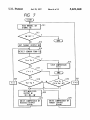
FIG. 7
READ MANUAL Sw
SIGNAL Sm
13“
S12
Y
T!
N
(:21)
SET TARGET OUTPUT wo
~
N814
DETECT SENSOR TEMP Ts
‘
N816
STOP COMPRESSOR
w: 0
END
S24
s
E=T
N
Y =
S]
'"L
SET MODIFIED
OUTPUT RT
9
S21
s
F=0
Y
1322
m = R0 - AW
N323
DRIVE COMPRESSOR BY
REDUCED OUTPUT
w=wT
_______.____l
T
Nszo
DRIVE COMPRESSOR BY
TARGET OUTPUT
w=wO
I__________
US. Patent
Jul. 29, 1997
Sheet 7 of 13
5,651,260
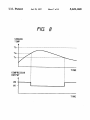
FIG. 8
SENSOR
TEMP
Tb
Ta- ---------------- --,
Tc
I
TIME
COMPRESSOR
OUTPUT
A
W0
W1 —
TIME
US. Patent
Jul. 29, 1997
Sheet 8 of 13
5,651,260
US. Patent
FIG.70
Jul. 29, 1997
Sheet 9 0f 13
5,651,260
U.S. Patent
Jul. 29, 1997
Sheet 10 0f 13
5,651,260
?
US. Patent
Jul. 29, 1997
Sheet 11 0f 13
5,651,260
US. Patent
Amlwvjizm
Jul. 29, 1997
_l_
3to
Sheet 12 of 13
5,651,260
U.S. Patent
153%2:a
Jul. 29, 1997
Sheet 13 of 13
m
m
E.3
NF
5,651,260
5,651,260
1
2
CONTROL APPARATUS AND NIETHOD FOR
ACTUATING AN ELECTRICALLY DRIVEN
COMPRESSOR USED IN AN AIR
CONDITIONING SYSTEM OF AN
AUTOMOTIVE VEHICLE
output of the compressor in response to a detected increase
of the inside or peripheral temperature of the control system,
thereby stabilizing the operation of the compressor and
assuring reliability of the air conditioning system for an
automotive vehicle.
To accomplish above and other related objects, a ?rst
aspect of the present invention provides a control apparatus
for actuating an electrically driven compressor equipped in
BACKGROUND OF THE INVENTION
1. Field of the Invention
The present invention generally relates to a control appa
ratus and a method for actuating an electrically driven
compressor used in an air conditioning system of an auto
10
motive vehicle, which is capable of promptly and adequately
supplied to the electrically driven compressor in accordance
with the signal generated from the temperature sensor.
According to features of the preferred embodiments. the
adjusting the output of the compressor in response to a
detected increase of the inside or peripheral temperature of
the control system. thereby stabilizing the operation of the
compressor and assuring reliability of the air conditioning
system.
2. Prior Art
A control system of an electric compressor is generally
temperature sensor detects a temperature of any one of a heat
radiator such as a heat sink. a micro computer or like
processing unit. a relay, a (switching) power unit, and an
electrolytic capacitor substantially determining the life of
20
subjected to heat generation due to power consumption
when it actuates the compressor. For example, an electrically
driven compressor, when it has an output of 2 KW, will
cause a heat generation of approximately 40 W which
corresponds to 2% of the overall output. Various electronic
components inside the control system are sensitive to heat;
25
thus, it is essentially important to protect these electronic
components for guaranteeing the performance of the control
system. To this end, the control system is generally provided
with a heat radiation device of normally an air-cooling type
or a water-cooling type. Speci?cations of the heat radiation
device needs to be designed based on the heat radiation
30
35
automatically stopped to prevent any damage from occur
ring by such excessive heat generations.
According to the above-described conventional systems,
when the temperature of the control system is extraordinar
ily increased, ?re only eifective countermeasure is to stop the
electric compressor; otherwise, the control system of the
electric compressor will be fatally damaged.
However. in View of the driving safety, sudden stop or
malfunction of an air conditioning system in an automotive
vehicle is not desirable and recommendable. For example,
sudden stop of the air conditioning system will make it
impossible to keep a clean view through the front windshield
glass since the glass will be clouded up with moisture.
Furthermore. a drive or passenger may be surprised or
frightened by the sudden stop of blow air. Needless to say,
such sudden stop or malfunction will make passengers feel
uncomfortable.
Still further, it is essentially important to assure a long life
of the control system of each electric compressor. In this
respect, an electrolytic capacitor, which essentially deter
the control system.
In addition, it is possible to provide an alarm indicator
generating an alarm Whenever the temperature detected by
the temperature sensor goes out of a predetermined allow
able range.
Furthermore, a second aspect of the present invention
provides a control apparatus for actuating an electrically
driven compressor equipped in an automotive vehicle, char
acterized by manual switch means, command generating
means, drive means, temperature sensing means, and adjust
ing means.
According to the second aspect compressor control
apparatus. the manual switch means allows a use to adjust an
conditions including ambient or peripheral temperatures and
electric power consumption.
Furthermore, in the event of unusual increase of
temperature, some of electrically driven compressor can be
an automotive vehicle, comprising: a temperature sensor
generating a signal representing a temperature of a compo
nent in the control apparatus; and control means connected
to the temperature sensor for adjusting an output command
output of the compressor and generates a request signal
representing a quantity of user’s manual adjustment. The
command generating means receives the request signal and
generates an output command supplied to the compressor in
accordance with the quantity of manual adjustment.
The drive means actuates the compressor based on the
output command. The temperature sensing means generates
a temperature signal representing a temperature of a com
ponent in the control apparatus. And the adjusting means
receives the temperature signal from the temperature sensing
means and generates a modi?ed output command, when the
45
temperature detected by the temperature sensing means
exceeds a predetermined upper-limit value. In this case, the
modi?ed output command is smaller than the output com
mand but larger than 0.
Still further, a third aspect of the present invention pro
50
vides a control apparatus for actuating an electrically driven
compressor equipped in an automotive vehicle. character
ized by manual switch means, target output means, tem
perature sensing means, modi?ed output means, command
generating means, and drive means.
55
According to the third aspect compressor control
apparatus, the manual switch means allows a use to adjust an
mines the life of the electric compressor control system
since its life is signi?cantly short. needs to be kept safely so
output of the compressor and generates a request signal
representing a quantity of user’s manual adjustment. The
target output means receives the request signal from the
as not to suffer from increase of temperature.
manual switch means and obtains a target output of the
SUMMARY OF THE INVENTION
In view of the above-described problems encountered in
the prior art, the present invention has a principal object to
compressor. In this case, the target output is proportional to
the quantity of user’s manual adjustment.
The temperature sensing means generates a temperature
signal representing a temperature of a component in the
provide a control apparatus and a method for actuating an 65 control apparatus. The modi?ed output means receives the
electric compressor used in an air conditioning system.
temperature signal from the temperature sensing means, and
which is capable of promptly and adequately suppressing the
obtains a modi?ed output when the temperature detected by
5,651,260
3
4
the temperature sensing means exceeds a predetermined
upper limit. The modi?ed output is set smaller than the target
A ?fth step is to obtain an output command in such a
manner that the output command is equalized to the target
output obtained by the target output means but larger than 0.
output when the temperature is within a predetermined
The command generating means generates an output
allowable range while the output command is reduced to a
command supplied to the compressor in such a manner that
modi?ed value larger than 0 when the temperature exceeds
the output command is equalized to the target output when
the temperature detected by the temperature sensing means
is within a predetermined allowable range while the output
command is equalized to the modi?ed output when the
temperature detected by the temperature sensing means
the upper limit. And. a sixth step is to actuate the compressor
based on the output command.
exceeds the upper limit. And, the drive means actuates the
compressor based on the output command generated from
the command generating means.
Yet further, a fourth aspect of the present invention
provides a control apparatus for actuating an electrically
driven compressor equipped in an automotive vehicle, char
acterized by manual switch means, target output means,
temperature sensing means, modi?ed output means, emer
10
acterized by the following ?rst to eighth steps.
15
gency means, cormnand generating means, and drive means.
_According to the fourth aspect compressor control
apparatus, the manual switch means allows a use to adjust an
output of the compressor and generates a request signal
representing a quantity of user’s manual adjustment. The
target output means receives the request signal from the
manual'switch means and obtains a target output of the
compressor, which is proportional to the quantity of user’s
25
30
35
ture sensing means exceeds a predetermined critical value
' higher than the upper limit.
The command generating means generates an output
command supplied to the compressor in such a manner that
45
50
And, the drive means actuates the compressor based on
the output command generated from the command generat
ing means.
Moreover, the present invention provides the method for
actuating the electrically driven compressor of an air con
ditioning system installed in an automotive vehicle.
More speci?cally, a ?fth aspect of the present invention
provides a control method for actuating an electrically
driven compressor equipped in an automotive vehicle, com
55
prising the following ?rst to sixth steps.
A ?rst step is to read a request signal representing a
quantity of user’s manual adjustment. A second step is to set
a target output of the compressor based on the request signal.
A third step is to detect a temperature of a component in the 65
control apparatus. A fourth step. is to judge whether the
temperature is larger than a predetermined upper limit.
exceeds the upper limit. And, an eighth step is to actuate the
compressor based on the output command.
Still further, a seventh aspect of the present invention
provides a control method for actuating an electrically
driven compressor equipped in an automotive vehicle, char
acterized by the following ?rst to tenth steps.
from the temperature sensing means, and forcibly stops the
compressor when the temperature detected by the tempera
the output command is equalized to the target output when
the temperature detected by the temperature sensing means
is within a predetermined allowable range while the output
command is equalized to the modi?ed output when the
temperature detected by the temperature sensing means is
higher than the upper limit but lower than the critical value.
target output by a predetermined correction value. The
modi?ed output is smaller than the target output but larger
equalized to the modi?ed output, when the temperature
temperature signal from the temperature sensing means, and
obtains a modi?ed output when the temperature detected by
the temperature sensing means exceeds a predetermined
upper limit
The modi?ed output is set smaller than the target output
obtained by the target output means but larger than 0.
The emergency means receives the temperature signal
A ?rst step is to read a request signal representing a
quantity of user’s manual adjustment. A second step is to set
a target output of the compressor based on the request signal.
In this case, the target output is proportional to the quantity
of user’s manual adjustment.
A third step is to detect a temperature of a component in
the control apparatus. A fourth step is to judge whether the
temperature is larger than a predetermined upper limit. A
?fth step is to generate an output command equalized to the
target output, when the temperature is within a predeter
mined allowable range.
A sixth step is to set a modi?ed output by reducing the
than 0. A seventh step is to generate an output command
manual adjustment.
The temperature sensing means generates a temperature
signal representing a temperature of a component in the
control apparatus. The modi?ed output means receives the
Furthermore, a sixth aspect of the present invention
provides a control method for actuating an electrically
driven compressor equipped in an automotive vehicle, char
A ?rst step is to read a request signal representing a
quantity of user’s manual adjustment. A second step is to set
a target output of the compressor based on the request signal,
so that the target output is proportional to the quantity of
user’s manual adjustment. A third step is to detect a tem
perature of a component in the control apparatus.
A fourth step is to judge whether the temperature is larger
than a predetermined critical value. A ?fth step is to stop the
compressor when the temperature exceeds the critical value,
regardless of the quantity of user’s manual adjustment.
A sixth step is to judge whether the temperature is larger
than a predetermined upper limit. In this case, the upper limit
is lower than the critical value. A seventh step is to generate
an output command equalized to the target output when the
temperature is within a predetermined allowable range. An
eight step is to set a modi?ed output by reducing the target
output by a predetermined correction value. The modi?ed
output is smaller than the target output but larger than 0. A
ninth step is to generate an output command equalized to the
modi?ed output when the temperature is higher than the
upper limit but lower than the critical value. And, a tenth
step is to actuate the compressor based on the output
command.
According to features of the preferred embodiment. it is
desirable to provide the following steps.
an eleventh step is to judge whether the temperature is
larger than a Predetermined reference value. The reference
value is set lower than the upper limit. And, a twelfth step
is to restore the output command to the target output when
the temperature falls below the reference value.
Thus, according to the present invention, it becomes
possible to promptly and adequately suppress the output of
5,651,260
5
6
the compressor in response to a detected increase of the
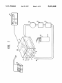
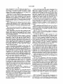
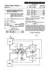
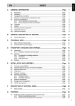
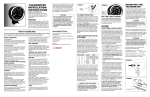
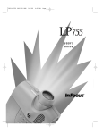
A control unit 1, connected to a battery 16, receives DC
(direct-current) power from battery 16. The control unit 1
comprises a drive power output section 4, a micro computer
6, a relay 7, a switching power unit 8, an electrolytic
capacitor 9, and a temperature sensor 20. The drive power
output section 4 converts the supplied DC power into AC
inside or peripheral temperature of the control system,
thereby stabilizing the operation of the compressor and
assuring reliability of the air conditioning system for an
automotive vehicle.
BRIEF DESCRIPTION OF THE DRAWINGS
(alternating-current) form and supplies thus converted AC
power to an electrically driven compressor 11 connected to
control unit 1.
The above and other objects. features and advantages of
the present invention will become more apparent from the
following detailed description which is to be read in con
The switching power unit 8 converts the voltage of battery
16 into a voltage required in the drive power output section
junction with the accompanying drawings, in which:
4. The electrolytic capacitor 9, connected in parallel to
switching power unit 8, absorbs current and voltage ripples
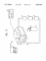
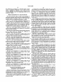
FIG. 1 is a view showing a schematic arrangement of a
control system for an electrically driven compressor in
accordance with a ?rst embodiment of the present invention;
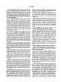
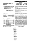
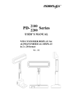
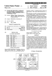
FIGS. 2A through 2D are views showing the correlations
when the drive power output section 4 converts the voltage
of battery 16 into AC form. The relay 7 opens or closes the
power supplying circuit connecting battery 16 and drive
among temperature, output, power consumption, and cool
ing ability in the electric compressor control system;
FIG. 3 is a circuit block diagram showing the control
system for the electrically driven compressor in accordance
with the present invention;
20
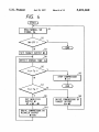
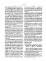
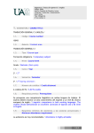
FIG. 4 is a ?ow chart showing a control routine performed
by the control system for actuating the compressor in
accordance with the present invention;
power output section 4.
The micro computer 6 controls the power conversion
performed in the drive power output section 4 in response to
the quantity of a user’s manual adjustment entered through
an operating section 15. The operating section 15, connected
to the control unit 1 via a signal line such as harness, is
usually disposed on the instrument panel in a passenger
compartment of an automotive vehicle.
The micro computer 6 further receives a detection signal
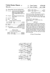
FIG. 5 is a time chart showing an output control of the 25
electric compressor in relation to a detected temperature in
from the temperature sensor 20 to adjust the power conver
accordance with the present invention;
sion performed in the drive power output section 4 in
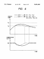
FIG. 6 is a time chart showing another output control of
the electric compressor in relation to a detected temperature
in accordance with the present invention;
FIG. 7 is a ?ow chart showing another control routine
response to the detected sensor temperature.
Thus, the micro computer 6 drives a motor of compressor
30
11 in accordance with not only the user’s request (i.e.
quantity of user’s manual adjustment) but also the detected
performed by the control system for actuating the compres
sensor temperature. In the driving operation of compressor
sor in accordance with the present invention;
FIG. 8 is a time chart showing an output control of the
electric compressor in relation to a detected temperature in
11, electric power is chie?y consumed in the drive power
output section 4.
35
accordance with the present invention;
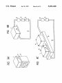
FIGS. 9A through 9C are views showing schematic
arrangements of a control system for an electrically driven
compressor in accordance with a second embodiment of the
40
present invention;
FIG. 10 is an arrangement of a control system for an
electrically driven compressor in accordance with a third
embodiment of the present invention;
FIG. 11 is an arrangement of a control system for an 45
electrically driven compressor in accordance with a fourth
embodiment of the present invention;
FIG. 12 is an arrangement of a control system for an
electrically driven compressor in accordance with a ?fth
embodiment of the present invention;
50
FIG. 13 is an arrangement of a control system for an
electrically driven compressor in accordance with a sixth
embodiment of the present invention; and
FIG. 14 is an arrangement of a control system for an 55
electrically driven compressor in accordance with a seventh
embodiment of the present invention.
DETAILED DESCRIPTION OF THE
PREFERRED EMBODIMENTS
Preferred embodiments of the present invention will be
explained in greater detail hereinafter, with reference to the
accompanying drawings. Identical parts are denoted by
identical reference numerals throughout the views.
FIG. 3 shows a circuit arrangement of the control system
of an electrically driven compressor in accordance with the
present invention.
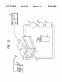
FIG. 1 shows a schematic arrangement of the control
system for an electrically driven compressor in accordance
with a ?rst embodiment of the present invention. The control
unit 1 comprises a printed circuit board 3 on which micro
computer 6, relay 7 and switching power unit 8 are mounted.
The micro computer 6 is connected to the temperature
sensor 20 (through a conductive path on the printed circuit
board 3). The temperature sensor 20 is disposed inside the
housing 2 of control unit 1.
The drive power output section 4 is located under the
printed circuit board 3 and brought into direct contact with
a heat sink 5 at the bottom thereof. The heat sink 5, serving
as a water-cooling type radiator, receives cooling water
forcibly circulated by a pump 12 through a hose 10. A water
cooling unit 13, disposed in series and upstream of pump 12,
is connected to pump 12 through hose 10, in order to cool
down the circulated hot water before it is sucked up by pump
12. A unit disposed upstream of water cooling unit 13 is a
heat generator 14 serving as a heat generating source other
than control unit 1.
Housing 2 and heat sink 5 are integrally united as a single
package accommodating the control unit 1.
The operating section 15 has a knob slidable in a right and
left direction. Users can manipulate this knob to adjust the
output of compressor 11. Harness outgoing to compressor 11
or entering from battery 16 or operating section respectively
passes through the wall of housing 2 and connected to the
printed circuit board 3, although not shown in the drawings.
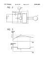
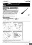
FIGS. 2A through 2D show the correlations among vari
ous factors. such as temperature, output. power
consumption. and cooling ability, in the electric compressor
control system.
5,651,260
7
8
As illustrated in FIG. 2A, the electric power consumption
increases with increasing output. As illustrated in FIG. 2B,
the heat generation inside the control unit 1, i.e. inner
temperature, is increased in proportion to the increase of the
electric power consumption. As illustrated in FIG. 2C, the
inner temperature increases with increasing outer tempera
The critical temperature Tb is a fairly high temperature that
possibly causes the fatal damage unavoidable without shut
down of the electric compressor control system.
When the sensor temperature Ts is not larger than the
critical temperature Tb, the control routine proceeds to step
ture (temperature outside the control unit 1). Furthermore, as
illustrated in FIG. 2D, the inner temperature is reduced with
temperature Ts is larger than a predetermined upper-limit
temperature Ta.
When the sensor temperature Ts is not larger than the
S7 to further make a judgement as to whether the sensor
increasing cooling ability.
It is now assumed that pump 12 is out of order, and the
water circulation amount is so reduced that the cooling
ability is lowered from “D” to “E”. In this case, the inner
upper-limit temperature Ta, the control routine proceeds to
temperature will exceed the predetermined upper limit if the
compressor 11 is driven at the output J. The inner tempera
ture is detected by temperature sensor 20 and sent to micro
computer 6. In response to the detection of such an excessive
15
increase of inner temperature, micro computer 6 adjusts the
power conversion performed by the drive power output
the user.
section 4 so as to reduce the output of compressor 11 to the
level of output K where the inner temperature is equal to the
step S8 to set the output command W to the target output W0
obtained in step S3 (W=W0) and send this command to the
compressor 11, thereby driving the compressor 11 in direct
proportion to the user’s request. In other words, the tem
perature Ta forms the reference or criterion point for judging
whether the compressor 11 should be driven as requested by
20
After completing step S8, the control routine returns to
step S1 to repeat the above-described processing.
On the other hand, when the sensor temperature Ts is
predetermined upper limit.
According to the correlation shown in FIG. 2C, an upper
limit of an outer temperature corresponding to the upper
larger than the upper-limit temperature Ta (“YES” in step
sponding inner temperature will exceeds the upper limit
modi?ed output W1 (W=W1) and sends this command to the
compressor 11, thereby driving the compressor 11 at a
S7), micro computer 6 proceeds to step S9 to set a modi?ed
output W1 which is smaller than the target output-W0 by
limit of the inner temperature can be identi?ed in a one-to
AW,
i.e. W1=W0—AW (>0). Subsequently, in step S10,
25
one manner when the output of the compressor 11 is known.
micro computer 6 sets the output command W to the
For example, when the outer temperature is “C”, the corre
when the compressor 11 is driven at the output H, but will
be identical with the upper limit when the compressor 11 is
driven at the output I. Thus, measuring an outer temperature
slightly smaller output compared with the user’s request.
30
In other words, the sensor temperatm'e Ts is higher than
the allowable upper-limit temperature Ta but less than the
critical temperature Ta in this case; therefore, the micro
computer 6 basically continues to drive compressor 11
although the output command W is set lower than the user’s
35
request.
makes it possible to indirectly detect the corresponding inner
temperature.
Furthermore, according to the correlation shown in FIG.
2B, when the electric power consumption is increased from
“B” to “A”, the inner temperature will exceed the upper limit
if the compressor 11 is driven at the output F. Hence, the
output of compressor 11 needs to be reduced to the level of
output G where the inner temperature is identical with the
upper limit.
Next, an operation of the present invention will be
explained with reference to FIG. 4 which shows a control
After completing step S10, the control routine returns to
step S4 to repeat the processing of step S4 and below.
40
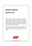
FIG. 5 is a time chart showing a change of compressor
output in relation to a detected temperature in accordance
with the present invention.
'
As shown in FIG. 5, the output command W of the
routine performed by the control system for actuating the
compressor 11 is reduced from W0 to W1 when the sensor
compressor in accordance with the present invention.
First, in step S1, micro computer 6 reads a manual switch
temperature Ts exceeds the allowable upper-limit tempera
signal Sm from the operating section 15, since the manual
switch signal Sm represents a user’s request entered through
manipulation of the slidable knob provided on the operating
mand W at a constant value W1 for a while unless the sensor
section 15.
Next, in step S2, micro computer 6 makes a judgement as
to whether the switch knob is in an OFF position. If the
ture Ta. The micro computer 6 maintains the output com
temperature Ts exceeds the critical temperature Tb (Steps
S4, S5, S7, S9 and S10 of FIG. 4). In the event the sensor
temperature Ts accidentally reaches the critical temperature
50
Tb as shown by an alternate long and two dashes line in FIG.
5, micro computer 6 immediately changes the output com
mand W to 0 so as to forcibly stop the compressor 11 (Steps
S5 and S6 of FIG. 4).
knob somewhere other than the OFF position (i.e. “NO” in
On the other hand, when the increase of sensor tempera
step S2), the control routine proceeds to step S3 wherein a 55 ture Ts is relatively moderate as shown by a solid line in FIG.
target output W0 of compressor 11 is determined based on
5, micro computer 6 continues to drive compressor 11 at the
the manipulation volume of the knob slidable on the oper
reduced output W1 until the sensor temperature Ts falls
judgement is “YES” in step S2, this control routine is ceased
at this moment. On the other hand, if the user sets the switch
ating section 15. The target output W0 is proportional to the
user’s request.
below the allowable upper-limit temperature Ta. Once the
sensor temperature Ta falls within the allowable range,
micro compressor 6 restores the output command W to the
target output W0 so as to drive the compressor 11 in
Next, in step S4, micro computer 6 reads a sensor tem
perature Ts detected by temperature sensor 20. Then, lit is
judged in step S5 whether the sensor temperature Ts is larger
than a predetermined critical temperature Tb. When the
sensor temperature Ts exceeds the critical temperature Tb,
the control routine proceeds to step S6 to set the output
command W to 0 (W=0) and send this command to the
compressor thereby forcibly stopping the compressor 11.
accordance with the user’s request. i.e. in direct proportion
to the manipulation volume of the knob slidable on the
operating section 15 (Steps S1-S5. S7 and S8 of FIG. 4).
65
Although FIG. 5 shows the reduction amount AW as a
constant value. it is desirable to increase the reduction
amount AW in accordance with the di?’erence between
5,651,260
9
sensor temperature Ts and allowable upper-limit Ta, i.e.
AW=k1-(Ts-Ta), as shown by a solid line in FIG. 6. Using
such setting, it becomes possible to eliminate sudden
changes of the compressor output as well as to suppress the
overshoot of the sensor temperature Ts.
Furthermore, it is also desirable to increase the reduction
amount AW in accordance with the time deviation of the
di?erence between sensor temperature Ts and allowable
upper-limit Ta in addition to the difference itself, i.e.
AW=k1~(Ts—Ta)-i-k2-A('I‘s—Ta)/At, as shown by an alternate
long and dash line in FIG. 6. Using such setting. it becomes
10
On the other hand. when the sensor temperature Ts is
larger than the upper-limit temperature Ta (“YES” in step
S18), micro computer 6 proceeds to step S22 to set a
modi?ed output W1 which is smaller than the target output
W0 by AW, i.e. W1=W0—AW (>0). Subsequently, in step
10
possible to further quicken the convergence of sensor tem
perature Ts.
Next, a modi?ed operation of the present invention will be
explained with reference to FIG. 7 which shows another
control routine performable by the control system for actu
ating the compressor in accordance with the present inven
tion.
The control routine shown in FIG. 7 is different from that
of FIG. 4 in that some hysteresis is provided in the setting
of allowable range.
request.
20
More speci?cally, in step S11, micro computer 6 reads
manual switch signal Sm from the operating section 15, the
manual switch signal Sm representing the user’s request
entered through manipulation of the slidable knob provided
on the operating section 15.
S23, micro computer 6 sets the output command W to the
modi?ed output W1 (W=W1) and sends this command to the
compressor 11. thereby driving the compressor 11 at a
slightly smaller output compared with the user’s request.
In other words, the sensor temperature Ts is higher than
the allowable upper-limit temperature Ta but less than the
critical temperature Ta in this case; therefore, the micro
computer 6 basically continues to drive compressor 11
although the output command W is set lower than the user’s
25
After completing step S23. ?ag F is set to 1 (i.e. F=l) to
indicate that compressor 11 undergoes the output reduction
control in accordance with the present invention. Then, the
control routine returns to step S14 to repeat the processing
of step S14 and below.
FIG. 8 is a time chart showing a change of compressor
output in relation to a detected temperature in accordance
with the present invention.
As shown in FIG. 8, the output command W of the
compressor 11 is reduced from W0 to W1 when the sensor
Next, in step S12, micro computer 6 makes a judgement
temperature Ts exceeds the allowable upper-limit tempera
as to whether the switch knob is in the OFF position. If the
ture Ta. The micro computer 6 maintains the output com
mand W at the reduced value W1 for a while unless the
switch knob somewhere other than the OFF position (i.e. 30 sensor temperature Ts exceeds the critical temperature Tb. In
judgement is “YES” in step S12, this control routine is
ceased at this moment. On the other hand, if the user sets the
“NO” in step S12), the control routine proceeds to step S13
the event the sensor temperature Ts accidentally reaches the
wherein target output W0 of compressor 11 is determined
based on the manipulation volume of the knob slidable on
the operating section 15. The target output W0 is propor
tional to the user’s request.
Next, in step S14, micro computer 6 reads sensor tem
perature Ts detected by temperature sensor 20. Then, it is
judged in step S15 whether the sensor temperature Ts is
critical temperature Tb, micro computer 6 immediately
changes the output command W to 0 so as to forcibly stop
the compressor 11 (Steps S15 and S16 of FIG. 7).
35
On the other hand, when the increase of sensor tempera
ture Ts is relatively moderate, micro computer 6 continues to
drive compressor 11 at the reduced output W1 until the
sensor temperature Ts falls below the temperature Tc. The
larger than predetermined critical temperature Tb. When the
temperature Tc is set lower than Ta by AT. It means that the
sensor temperature Ts exceeds the critical temperature Tb. 40
compressor 11 is continuously driven at the reduced 20
the control routine proceeds to step S16 to set the output
output W1 even the sensor temperature Ts falls below the
command W to 0 (W=0) and send this command to the
upper-limit temperature Ta unless it reaches the temperature
compressor 11, thereby forcibly stopping the compressor 11.
The critical temperature Tb is a fairly high temperature that
possibly causes the fatal damage unavoidable without shut
down of the electric compressor control system.
Tc (Steps S14, S15, S17, S19, S22, S23 and S24 of FIG. 7)
Namely. the di?’erence AT (=Ta-Tc) is a hysteresis set for
45
sensor temperature Ts.
When the sensor temperature Ts is not larger than the
Once the sensor temperature Ts falls below the tempera
ture Tc, micro computer 6 restores the output command W
critical temperature Tb, the control routine proceeds to step
S17 to check whether or not a ?ag F is 1 (i.e. F=1?). This flag
F is used to indicate the fact that, when F is 1, compressor
11 undergoes the output reduction control in accordance
with the present invention. When the ?ag F is “0”, i.e. “NO”
in step S17, the control routine proceeds to step S18. On the
contrary, when the ?ag F is “l”. i.e. “YES” in step S17, the
control routine proceeds to step S19.
In step S18. micro computer 6 makes a judgement as to
whether the sensor temperature Ts is larger than predeter
mined upper-limit temperature Ta.
avoiding the hunting phenomenon in the convergence of
to the target output W0 so as to drive the compressor 11 in
accordance with the user’s request, i.e. in direct proportion
to the manipulation volume of the knob slidable on the
55
operating section 15 (Steps S19 and S20 of FIG. 7). Then,
the flag F is reset to 0. i.e. F=0 (Step S21 of FIG. 7), thereby
indicating that the output reduction control of compressor 11
in accordance with the present invention is terminated.
In this manner, the present invention makes it possible to >
When the sensor temperature Ts is not larger than the
prevent the control unit from being damaged or
malfunctioning, and also to prevent an electrically driven
upper-limit temperature Ta, the control routine proceeds to
compressor from being suddenly stopped except emergency
step S20 to set the output command W to the target output
W0 obtained in step S13 (W=W0) and send this command
to the compressor 11, thereby driving the compressor 11 in
direct proportion to the user’s request.
conditions which require the shutdown of the compressor.
After completing step S20, ?ag F is set to 0 (i.e. F=O), and
Other Embodiments
65
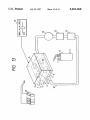
FIGS. 9A through 9C show schematic arrangements of a
control system for an electrically driven compressor in
the control routine returns to step S11 to repeat the above
accordance with a second embodiment of the present inven
described processing.
tion. According to the second embodiment of the present
5,651,260
11
12
invention, the temperature sensor 20 is attached on the heat
sink 5 to directly detect the temperature of heat sink 5.
In an embodiment shown in FIG. 9A, heat sinkS is cooled
down by an air-cooling unit 17 with an axial-?ow fan. In an
of switching loss, the temperature of switching unit 8
possibly exceeds 80° C. Upon sensor 20 detecting this
excessive increase of temperature, micro computer 6 adjusts
embodiment shown in FIG. 9B, heat sink 5 is cooled by
i.e. reduces the output command W from W0 to W1 until the
sensor temperature Ts falls below within the allowable range
less than 80° C.
FIG. 13 shows an arrangement of a control system for an
electrically driven compressor in accordance with a sixth
embodiment of the present invention. The sixth embodiment
the power conversion in the drive power output section 4,
water in the same manner as the ?rst embodiment- Accord
ing to an embodiment shown in FIG. 9C, heat sink 5 is
cooled down by a heat sink package 18, where electric
compressor control unit 1 is directly mounted on the heat
sink package 18 by means of screws 19. The‘heat sink
package 18 is a water-cooling type which mounts the heat
10
generator 14 together with control unit 1.
If the axial-?ow fan equipped air-cooling unit 17 or the
water cooling unit 13 is out of order, or the connection
between the control unit 1 and the heat sink package 18 is
not su?iciently tight (for example, due to looseness of
screws 19), the cooling ability will be fairly lowered accom
is substantially identical with the ?rst embodiment except
that the temperature sensor 20 is directly attached on elec
15
trolytic capacitor 9. The allowable upper-limit of electrolytic
capacitors is approximately 80° C. (i.e. Ta=80° C.).
When the cooling ability is lowered due to, for example,
disorder of pump 12, the temperature of electrolytic capaci
may exceeds the allowable upper-limit (Ta). Receiving the
tor 9 possibly exceeds 80° C. Upon sensor 20 detecting this
excessive increase of temperature, micro computer 6 adjusts
the power conversion in the drive power output section 4,
temperatm'e of heat sink 5 from temperature sensor 20,
micro computer 6 adjusts the power conversion in the drive
power output section 4, i.e. reduces the output command W
i.e. reduces the output cormnand W from W0 to W1 until the
sensor temperature Ts falls below within the allowable range
less than 80° C.
panied by an increase of temperature of heat sink 5 which
from W0 to WI when the sensor temperature Ts exceeds the
In general, the life of electrolytic capacitors is doubled by
upper-limit temperature Ta until ?ie sensor temperature Ts
falls below within the allowable range.
If the temperature of heat sink 5 exceeds the critical
reducing the temperature by an amount of 10° C. Hence, the
electrolytic capacitor 9, when it has a life of 5,000 hours at
85° C., can extend its life to 10,000 hours by setting the
allowable upper-limit temperature (Ta) at 75° C. in this
25
temperature (Tb), micro computer 6 immediately stops the
compressor 11 (i.e. W=0) regardless of the knob position of
operating section 15.
embodiment.
FIG. 14 is an arrangement of a control system for an
electrically driven compressor in accordance with a seventh
embodiment of the present invention. The seventh embodi
ment is substantially identical with the ?rst embodiment
except that an alarm indicator 21 is provided on the oper
FIG. 10 shows an arrangement of a control system for an
electrically driven compressor in accordance with a third
embodiment of the present invention. The third embodiment
is substantially identical with the ?rst embodiment except
ating section 15. According to the seventh embodiment,
that the temperature sensor 20 is directly attached on micro
computer 6. The allowable upper-limit temperature of micro
computers is approximately 80° C. (i.e. Ta=80° C.).
When the cooling ability is lowered, the temperature of
micro computer 6 possibly exceeds 80° C. If the sensor
temperature Ts exceeds 80° C., micro computer 6 adjusts the
power conversion in the drive power output section 4, i.e.
micro computer 6 sends an alarm signal to operating section
35 15 as soon as the sensor temperature Ts exceeds the upper
limit temperature (Ta). Upon receiving the alarm signal, the
alarm indicator 21 is turned on to inform passengers in a
compartment room of an automotive vehicle of the output
reduction operation of the compressor.
This invention may be embodied in several forms without
reduces the output command W from W0 to W1 until the
departing from the spirit of essential characteristics thereof,
sensor temperature Ts falls below within the allowable range
the present embodiments as described are therefore intended
less than 80° C.
to be only illustrative and not restrictive, since the scope of
FIG. 11 shows an arrangement of a control system for an
the invention is de?ned by the appended claims rather than
electrically driven compressor in accordance with a fom'th 45 by the description preceding them, and all changes that fall
embodiment of the present invention. The fourth embodi
within metes and bounds of the claims, or equivalents of
ment is substantially identical with the ?rst embodiment
such metes and bounds, are therefore intended to be
except that the temperature sensor 20 is directly attached on
embraced by the claims.
relay 7. The allowable upper-limit of relays is approximately
What is claimed is:
80° C. (i.e. Ta=80° C.).
For example, if the heat generation in relay 7 is largely
increased due to excessive current, the temperature of relay
7 will exceed 80° C. Upon sensor 20 detecting this excessive
increase of temperature, micro computer 6 adjusts the power
conversion in the drive power output section 4, i.e. reduces
the output command W from W0 to W1 until the sensor
temperature Ts falls below within the allowable range less
than 80° C.
50
1. A control apparatus for actuating an electrically driven
compressor equipped in an automotive vehicle, comprising:
a temperature sensor generating a signal representing a
temperature of a component in the control apparatus;
and
55
control means connected to said temperature sensor for
adjusting an output command supplied to said electri
cally driven compressorin accordance with said signal
FIG. 12 shows an arrangement of a control system for an
generated from said temperature sensor.
2. The compressor control apparatus de?ned by claim 1,
electrically driven compressor in accordance with a ?fth
embodiment of the present invention. The ?fth embodiment
is substantially identical with the ?rst embodiment except
that the temperature sensor 20 is directly attached on switch
heat radiator provided in said control apparatus.
3. The compressor control apparatus de?ned by claim 1,
ing power unit 8. The allowable upper-limit of switching
power units is approximately 80° C. (i.e. Ta=80° C.).
When the heat generation in the switching power unit 8 is
largely increased due to, for example, an excessive increase
wherein said temperature sensor detects a temperature of a
wherein said temperature sensor detects a temperature of a
65
micro computer provided in said control apparatus.
4. The compressor control apparatus de?ned by claim 1,
wherein said temperature sensor detects a temperature of a
relay provided in said control apparatus.