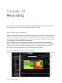
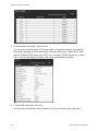
1
TruVision NVR 70 User Manual P/N 1073062-EN • REV B • ISS 18NOV15 Copyright © 2015 United Technologies Corporation. Interlogix is part of UTC Climate, Controls & Security, a unit of United Technologies Corporation. All rights reserved. Trademarks and patents Manufacturer Trade names used in this document may be trademarks or registered trademarks of the manufacturers or vendors of the respective products. Interlogix 2955 Red Hill Avenue, Costa Mesa, CA 92626-5923, USA Authorized EU manufacturing representative: UTC Fire & Security B.V. Kelvinstraat 7, 6003 DH Weert, The Netherlands FCC compliance Canada Class A: This equipment has been tested and found to comply with the limits for a Class A digital device, pursuant to part 15 of the FCC Rules. These limits are designed to provide reasonable protection against harmful interference when the equipment is operated in a commercial environment. This equipment generates, uses, and can radiate radio frequency energy and, if not installed and used in accordance with the instruction manual, may cause harmful interference to radio communications. Operation of this equipment in a residential area is likely to cause harmful interference in which case the user will be required to correct the interference at his own expense. This Class A digital apparatus complies with Canadian ICES-003. Cet appareil mumérique de la classe A est conforme à la norme NMB-003 du Canada. ACMA compliance Notice! This is a Class A product. In a domestic environment this product may cause radio interference in which case the user may be required to take adequate measures. Certification N4131 EU directives 2004/108/EC (EMC directive): Hereby, UTC Fire & Security declares that this device is in compliance or with the essential requirements and other relevant provisions of Directive 2004/108/EC. 2012/19/EU (WEEE directive): Products marked with this symbol cannot be disposed of as unsorted municipal waste in the European Union. For proper recycling, return this product to your local supplier upon the purchase of equivalent new equipment, or dispose of it at designated collection points. For more information see: www.recyclethis.info. 2006/66/EC (battery directive): This product contains a battery that cannot be disposed of as unsorted municipal waste in the European Union. See the product documentation for specific battery information. The battery is marked with this symbol, which may include lettering to indicate cadmium (Cd), lead (Pb), or mercury (Hg). For proper recycling, return the battery to your supplier or to a designated collection point. For more information see: www.recyclethis.info. Contact information For contact information, see www.interlogix.com or www.utcfssecurityproducts.eu Content Important information 4 Chapter 1 Product introduction 5 Product overview 5 Default settings to access the device 5 Chapter 2 Physical installation 7 Installation environment 7 Unpacking the recorder and its accessories 7 Back panel description 8 HDD slots 9 Rack mounting 10 Chapter 3 Getting started 11 Power on the recorder 11 The startup wizard 11 Chapter 4 Operating instructions 16 Control the recorder 16 Front panel description 16 Access the web browser 17 Web browser interface 18 Chapter 5 Live view 20 Web browser live view 20 Custom views 22 Digital zoom 23 Control a PTZ dome camera 23 Chapter 6 Playback functionality 27 Overview of the playback view 27 The playback control toolbar 28 Display order of cameras on screen 30 Play back a recording 30 Synchronize play back across cameras 31 Playback speed 31 Digital zoom in playback 32 Capture snapshots 32 Create bookmarks 32 Chapter 7 Searching files 34 Advanced search video menu 34 Search for motion events in playback 35 Search and play back recordings by time and video type 36 Search and play back recordings by event 37 TruVision NVR 70 User Manual 1 Search bookmarked recordings 39 Search snapshots 39 Search event logs 39 Chapter 8 Archiving files 43 Overview of archiving 43 Manually archive files 43 Automatically archive files 44 Archive video clips 44 Export video recordings via TruVision Navigator 44 Using TruVision Player 45 Watermarking 46 Chapter 9 Web browser configuration 47 Windows operating system 47 Access the web browser 48 Configure the recorder via the browser 48 Chapter 10 Camera setup 51 IP camera status 51 Import and export IP camera configuration settings 53 Camera recording settings 53 Camera OSD 55 Motion detection 56 Privacy mask 57 Camera tamper 58 Text overlay 59 V-stream encoding 60 Video analytics 60 Chapter 11 Network settings 62 Network settings 62 PPPoE settings 65 DDNS settings 65 NTP server settings 67 Email settings 67 Configure an FTP server to store snapshots 68 SNMP settings 69 Using a network storage system 69 UPnP settings 70 HTTPS settings 70 Network statistics 71 Chapter 12 Recording 73 Recording schedule 73 Auto archiving 75 Manual recording 77 Hot spare 77 2 TruVision NVR 70 User Manual Chapter 13 Alarm and event setup 79 Set up alarm inputs 79 Set up alarm outputs 80 Manual trigger 81 Buzzer settings 81 Alarm notification 82 Detect video loss 83 Alarm host setup 84 Chapter 14 Device management 85 Time and date settings 85 General recorder settings 86 Configuration files 88 Upgrade system firmware 89 Holiday schedules 89 Text insertion 90 Chapter 15 Storage management 92 HDD information 92 Add a network storage system 93 Install HDDs 94 Storage mode 95 S.M.A.R.T. settings 97 RAID settings 97 Chapter 16 User management 100 Add a new user 100 Customize a user’s access privileges 101 Delete a user 102 Modify a user 103 Change the Admin password 103 Chapter 17 System information 104 View system information 104 Appendix A Specifications 108 Appendix B Port forwarding information 110 Seeking further assistance 110 Appendix C TruVision Mac Safari Browser Plug-in v1.0 112 Overview 112 Plug-in installation 112 Appendix D Default menu settings 115 Index 126 TruVision NVR 70 User Manual 3 Important information Advisory messages Advisory messages alert you to conditions or practices that can cause unwanted results. The advisory messages used in this document are shown and described below. WARNING: Warning messages advise you of hazards that could result in injury or loss of life. They tell you which actions to take or to avoid in order to prevent the injury or loss of life. Caution: Caution messages advise you of possible equipment damage. They tell you which actions to take or to avoid in order to prevent damage. Note: Note messages advise you of the possible loss of time or effort. They describe how to avoid the loss. Notes are also used to point out important information that you should read. 4 TruVision NVR 70 User Manual Chapter 1 Product introduction Product overview This recorder is a high performance network video recorder that can store, search, export and manage video from up to 400 Mbps of incoming camera bandwidth, or up to 128 IP cameras. There are many redundancy features to ensure system stability failure such as RAID, hot spare mode, network redundancy, and redundant power supplies. It provides integration with the UTC portfolio of security solutions and offers a seamless product experience within the TruVision brand. The recorder can fully integrate with the license-free TruVision Navigator software, which is ideal for most commercial applications. It features an easy-to-use and intuitive web browser interface that enables remote configuration and secure viewing, searching, and playing back of video. Default settings to access the device Default user names and passwords See Table 1 on page 6 for the list of default user names and passwords. Go to Chapter 16 “User management” on page 100 for further information. TruVision NVR 70 User Manual 5 Table 1: Default user names and passwords User Description Administrator There can only be one administrator. The user name is “admin”. The name cannot be modified. The default password is 1234. Operator The default user name is “operator”. The default password is 2222. Guest The default user name is “guest”. The default password is 3333. Note: The default passwords should be changed for security reasons. Default network settings The network settings are: • IP address - 192.168.1.82 • Subnet mask - 255.255.255.0 • Gateway address - 192.168.1.1 • Ports: When using the browser: When using TruNav: RTSP port: 554 RTSP port: 554 HTTP port: 80 Server/Client software port: 8000 Go to “Web browser” on page 47 for further information. 6 TruVision NVR 70 User Manual Chapter 2 Physical installation This section describes how to install the recorder. Installation environment When installing your product, consider these factors: • Ventilation • Temperature • Humidity • Chassis load Ventilation: Do not block any ventilation openings. Install in accordance with the manufacturer’s instructions. Ensure that the location planned for the installation of the unit is well ventilated. Temperature: Consider the unit’s operating temperature (-10 to +55 ºC, 14 to 131 °F) and noncondensing humidity specifications (10 to 90%) before choosing an installation location. Extremes of heat or cold beyond the specified operating temperature limits may reduce the life expectancy of the recorder. Do not install the unit on top of other hot equipment. Leave 44 mm (1.75 in.) of space between rack-mounted NVR units. Humidity: Do not use the unit near water. Moisture can damage the internal components. To reduce the risk of fire or electric shock, do not expose this unit to rain or moisture. Chassis: Equipment weighing less than 15.9 kg (35 lb.) may be placed on top of the unit. Unpacking the recorder and its accessories When you receive the product, check the package and contents for damage, and verify that all items are included. There is an item list included in the package. If any of the items are damaged or missing, please contact your local supplier. Items shipped with the product include: TruVision NVR 70 User Manual 7 Chapter 2: Physical installation • AC power cords • Recorder • Hard drive kits • CD with software and manuals • TruVision NVR 70 Quick Start Guide • TruVision NVR 70 User Manual (on CD) • TruVision Recorder Operator Guide (on CD) Back panel description The figure below shows the back panel connections and describes each connector on a typical TVN 70 network video recorder. Details may vary for specific models. Before powering up the recorder, connect a main monitor for basic operation. Once all required connections are done, enter the relevant data in the setup wizard (see page 11). Note: For every hardwired alarm input, connect one wire to the input connection with the alarm number label and one wire to a Ground connection (labeled G). Figure 1: TVN 70 back panel connections 1. Description Use Specification One audio output Connect to speakers for audio output. RCA jack, 315mV, 600 ohms. Unbalanced. Line-level audio requires amplification. 8 TruVision NVR 70 User Manual Chapter 2: Physical installation 2. Description Use Specification One audio input Connect a microphone for bi-directional audio (not recorded) RCA jack, 315 mV, 40 kohms. Unbalanced. Line-level audio requires amplification. 3. eSATA Connect an optional eSATA drive to extend the internal storage. 4. 16 alarm inputs Connect physical alarms such as detectors, push buttons, etc. 5. Redundancy power supplies (X2) Connect two PSUs. 6. SFP port Plug a small form-factor pluggable transceiver into the port in order to connect fiber cables. 7. Ethernet ports Connect to a network. 8. USB 3.0 port (X2) Connect a USB device, CD/DVD burner or HDD. 9. Restart pin hole Access to the reset button. The PSUs are shipped with the recorder. Hold down the reset button for seven seconds to reset the network settings. Note: This might cause the cameras to stop recording and the software to be unable to connect to the recorder. 10. RS-232 input Text insertion for point-of-sale and ATM devices. Also used by technical support. See “Configure the RS-232 port” on page 90 for more information. 11. Eight alarm outputs Connect physical alarm outputs such as a siren, flash, relay. 12. Ground Connect to ground. HDD slots The TVN 70 has four rows of 4 HDD slots. This allows 16 HDDs to be connected. The slots are accessed from the front panel for easy expansion or replacement of the hard drives. Each HDD slot can support 4 or 6 TB HDDs. The total onboard storage capacity is 64 TB in RAID configuration, or 96 TB in a non-RAID configuration. The storage capacity can be further expanded by using the USB 3.0, eSATA, or NAS functionality. TruVision NVR 70 User Manual 9 Chapter 2: Physical installation Rack mounting The recorder is 3U rack mountable using a rack mount shelf. The rack mount ears included with the product are intended to fix the product in the rack, not to carry the full weight of the recorder. It can also be installed desk-based. 10 TruVision NVR 70 User Manual Chapter 3 Getting started Power on the recorder Before starting the recorder, connect at least one monitor. Otherwise, you will not be able to see the user interface and operate the device. The recorder comes equipped with a universal power supply that will auto-sense 110/240 V, 60/50 Hz. Note: It is recommended that an uninterruptible power supply (UPS) is used in conjunction with the device. To turn on the recorder: Plug in both power cords on the back panel. Once it is powered up, the status LEDs on the front panel will light up. To reboot the recorder: Connect to the recorder through the web browser interface or TruVision Navigator and reboot the recorder, if needed. See “Restart the recorder” on page 88 for more information. The startup wizard The recorder has an express installation wizard that lets you easily configure basic recorder settings when first used. It configures all cameras to default settings. The configuration of each camera and recorder can be customized as required later in the Configuration menu. Any changes you make to a setup configuration page are saved when you exit the page and return to the main wizard page. Note: If you want to set up the recorder with default settings only, click Next in each screen until the end. TruVision NVR 70 User Manual 11 Chapter 3: Getting started Important: Your TruVision device is delivered with default user name and password credentials for initial access, easy configuration and auto discovery. For security reasons, it is highly recommended to change the default credentials. To use the Startup wizard: 1. There are two ways to access the Startup wizard: In Internet Explorer enter the IP address of the TVN 70. The browser will automatically launch the startup wizard. Note: Use TruVision Device Manager to locate the recorder on the LAN and, if required, to change the recorder’s IP address. - Or On the recorder’s menu toolbar, click Configuration to display the configuration window. Click Start wizard now to immediately launch the startup wizard. 2. Select the preferred language for the system and resolution from the dropdown list and then click Next. 3. Enable or disable the option to start the wizard automatically when the recorder is turned on. Click Next. 4. User configuration: You can change the admin password and create additional users. To change the admin password, select the admin user line and click the Edit button. In the “Edit User” pop-up window, enter the default admin password, 1234, and the new password. You will be shown the security level of the new password: Low, Medium or High. Confirm the new password and click OK. Note: You must enter an admin password. To add a new user, enter the user information in the “Add user” section of the window and click OK. 12 TruVision NVR 70 User Manual Chapter 3: Getting started Caution: It is strongly recommended that you change the password of the administrator. Do not leave 1234 as the default password. Write it down in a safe place so that you do not forget it. If you should forget the password to your recorder, contact your supplier with the serial number of your recorder to obtain a secure code to reset it. Click Next to move to the next page or click Back to return to the previous page. 5. Time and date configuration: Select the desired system time and time zone. If Daylight saving time (DST) is required, check Enable DST and enter the desired summer and winter times. Note: The system time and date are visible on screen. However, the time and date shown on-screen are set in the camera settings. Click OK and then Next to move to the next page or click Back to return to the previous page. 6. HDD initialization: The hard drives are initialized at the factory. However if you wish to clear all data, click Initialize to initialize the selected HDD and Next to move to the next page, or Back to return to the previous page. TruVision NVR 70 User Manual 13 Chapter 3: Getting started 7. Search and add IP cameras: You can search the network for available IP cameras and add them to the recorder. To search for available cameras, click Search/Add. All the cameras found will be listed on screen. Select the desired cameras and click OK to add to your list. If you already know the specific camera to add, enter its IP address, protocol, user name, transfer protocol, registration mode, management port and password, and click OK. Click Next to move to the next page or click Back to return to the previous page. 8. Recording configuration: Configure your recording settings as required. The settings apply to all cameras connected to the recorder. 14 TruVision NVR 70 User Manual Chapter 3: Getting started Check the desired time lapse check box, TL-Hi or TL-Lo. To record motion detection events, check Enable Motion Detection Plan. To record alarm events, check Enable Alarm Input Plan. Click Next to move to the next page, or Back to return to the previous page. Note: You can configure the recording parameters of each individual camera for the different recording schedules in the recording menu. 9. When all the required changes have been entered, a summary page appears showing all the settings. Click Finalize to exit the Wizard. The recorder is now ready to use. For a description of the recorder interface, see “Web browser interface” on page 18. TruVision NVR 70 User Manual 15 Chapter 4 Operating instructions Control the recorder You operate the recorder through a browser interface, which provides full functionality for viewing, playback and recorder configuration. You can also use TruVision Navigator or TVRmobile. Please refer to the TruVision Navigator and TVRmobile user manuals for more information. You can use your preferred control method for any procedure, but in most cases we describe procedures using the browser. You can also use the TVK-800 keypad (from TVK-800 firmware version 1.0i) to control PTZ cameras directly or TVE-DEC10 decoder to display TVN 70 camera footage onto a local monitor. Please refer to the user manuals of these devices for more information. Front panel description The function button on the front panel lets you easily archive files. You can also open the front panel to access the HDDs in the recorder. The front panel can be locked with a key to limit access. The LED indicators light up to alert you of various conditions. See Figure 2 on page 17 for more information. 16 TruVision NVR 70 User Manual Chapter 4: Operating instructions Figure 2: TVN 70 front panel The controls on the front panel include: Table 2: Front Panel Elements Name Description 1. Front panel lock You can lock or unlock the front panel with a key. It provides access to the HDDs. 2. Status LEDs Alarm: A blinking RED light indicates that there is a sensor Alarm In. No light indicates no alarm. Internal: No light indicates that the recorder is currently recording video/audio. A blinking RED light indicates internal health failure. Network: A steady GREEN light indicates that the recorder is currently connected to a network. A blinking RED light indicates that the recorder is not connected to any network. HDD: A steady GREEN light indicates that the recorder is accessing the HDD in a read or write operation. A blinking RED light indicates HDD failure. No light indicates that the unit is in idle state. Archive: A steady GREEN light indicates that archiving is in progress. No light indicates no archiving in progress. 3. Archive button Press once to enter quick archive mode. Press twice to start archiving. If the USB stick has an LED, it will flash during archiving. 4. USB 3.0 port There is one USB port. Use the USB port to archive video or connect a USB CD/DVD burner. Access the web browser To access the recorder, open the web browser and enter the IP address or domain name assigned to the recorder. On the logon window, enter the default user ID and password. TruVision NVR 70 User Manual 17 Chapter 4: Operating instructions Default user values: User ID: admin User ID: operator User ID: guest Password: 1234 Password: 2222 Password: 3333 The default values for recorder network settings are: • IP address - 192.168.1.82 • Subnet mask - 255.255.255.0 • Gateway address - 192.168.1.1 • Server port: 8000 • Ports: When using the browser: When using TruNav: RTSP port: 554 RTSP port: 554 HTTP port: 80 Server/Client software port: 8000 For more information on port forwarding, see Appendix B “Port forwarding information” on page 110. Web browser interface The recorder’s web browser interface has an intuitive structure that allows you to configure the unit’s parameters quickly and efficiently. Each submenu item displays a setup menu that lets you edit a group of settings. Most menus are available only to system administrators. The browser window is divided into three sections. The currently selected submenu is highlighted in green. See Figure 3 below. 18 TruVision NVR 70 User Manual Chapter 4: Operating instructions Figure 3: Browser window 1. Menu toolbar: Setup options available for the selected menu function. Move the mouse over a menu function and click to select it. There are four menu modes: Live View, Playback, Log Search, and Configuration. 2. Submenu panel: Submenus for the selected menu function are displayed. Click an item to select it. 3. Setup menu: All the details for the selected submenu are displayed. Click a field to make changes. TruVision NVR 70 User Manual 19 Chapter 5 Live view Live view mode is the normal operating mode of the unit where you watch live images from the cameras. The recorder automatically enters into live view mode once powered up. Web browser live view The recorder web browser lets you view, record, and play back videos as well as manage all aspects of the recorder from any PC with Internet access. The browser’s easy-to-use controls give you live view to all the recorder functions. See Figure 4 below. Figure 4: Live view in the web browser interface Table 3: Description of live view in the web browser 1. 20 Name Description Custom view Lets you group selected cameras together in live view. See “Custom views” on page 22 for more information. TruVision NVR 70 User Manual Chapter 5: Live view 2. Name Description Camera live view and recording Select the camera for live viewing and recording. Click the button to start/stop live view from the selected camera. / / 3. Menu toolbar Click the button to start/stop local recording on your PC from the selected camera. Lets you navigate throught the following menus: • View live video • Play back video • Search for event logs • Configure settings • Log out of the interface 4. Viewer View live or playback video. 5. PTZ/Video parameters panel Hide/display the PTZ panel. 6. Display format Define how you want video to be displayed in the viewer: Single/multiview or full-screen. 7. Streaming and recording toolbar Switch between main stream and substream for all cameras. / / 8. Video function toolbar Start/stop live streaming from all cameras. Start/stop local recording from all cameras. Lets you do the following in live view: Digital zoom. Turn POS/ATM text insertion on/off. Take a snapshot. View previous and next camera respectively. If viewing in multiview format, live view moves to the next group of cameras for the selected number of video tiles. Turn audio on/off Turn microphone on/off 9. Presets Lists presets available and allows you to trigger presets. 10. Image settings Modify brightness, contrast, saturation and hue values between 0 and 128. 11. Preset tours Lists preset tours available and allows you to trigger preset tours. 12. Shadow tours Lists shadow tours available. TruVision NVR 70 User Manual 21 Chapter 5: Live view Custom views You can easily group cameras so that they appear in live view together. This allows you, for example, to quickly see all the cameras in a pre-defined part of the building such as a parking lot or different floors. You can change the name of a custom view as well as select which cameras in a custom view group are main stream and substream. To create a custom view of cameras: 1. Select the required multiscreen lay-out, depending on the amount of cameras you want to show in the custom view 2. Select a video tile for the camera that you want to appear in the custom view and click the camera button to enable live view ( ).The camera’s live view appears in the video tile. 3. Select another video tile and enable live view for the next camera to include in the custom view. Repeat for each camera to be included in the custom view. 4. Click the Add Custom View button . The list of selected cameras appears. Enter the name of the custom view in the text box. 5. Select which cameras will be main stream and which will be substream by clicking on each camera listed in the custom view. The camera button changes to show the streaming type: Main stream Substream 6. Click OK. The custom view is listed under “Custom Views”. To call up a custom view of cameras: 1. In the custom view list, double-click the desired custom view. The selected name is highlighted in green. The custom view cameras appear on screen. To edit a custom view of cameras: 1. Double-click the desired custom view and click the Stop All Viewing button to deselect all live views of the cameras in the group. 2. Click the Edit Custom View button list. . Select the desired custom view from the drop-down 3. To change the name of the custom view, enter a different name for selected custom view group. 22 TruVision NVR 70 User Manual Chapter 5: Live view 4. To change a camera’s streaming type, click the desired camera. The camera button changes to show the streaming type. 5. To add a camera to a custom view list, select the desired camera from the list of cameras not included in the custom view and click the button in front the camera name. The camera is added to the custom view list. To delete a custom view of cameras: 1. Double-click the desired custom view and click the Stop All Viewing button to deselect all live views of the cameras in the group. 2. Click the Delete Custom View button . The selected custom view is deleted. Digital zoom You can easily zoom in or out of a camera image in live view mode and playback using the digital zoom command. The zoom command magnifies the camera image four times. To quickly zoom in/out on a camera image: 1. Click the digital-zoom button green frame. in live view. When enabled, the digital zoom button has a 2. Left-click the mouse and drag the mouse over the area of interest. The selected area is magnified. 3. To exit digital zoom, click the digital zoom button again. The green frame on the button disappears. Control a PTZ dome camera The web browser interface lets you control the PTZ functions of a dome camera. Click a PTZ dome camera and use the PTZ controls on the interface to control the PTZ functions. If the display was in multiview format, it changes to full-screen format for the selected camera. See Figure 5 on page 24 for a description of the PTZ control panel. TruVision NVR 70 User Manual 23 Chapter 5: Live view Figure 5: PTZ controls panel 1. Directional pan/auto-scan buttons: Controls the movements and directions of the PTZ. Center button is used to start auto-pan by the PTZ dome camera. 2. Adjust speed of PTZ dome camera. 3. Adjust zoom, focus, and iris. 4. Turn on or off the camera light (Not used). 5. Lens initialization: Initialize the lens of a camera with a motorized lens, such as PTZ or IP cameras. This function helps to maintain lens focus accuracy over prolong periods of time. 6. Start or stop camera wiper (Not used). 7. Auxiliary focus: Automatically focus the camera lens for the sharpest picture. 8. Start selected preset/tour/shadow tour (depending on function selected). 9. List presets available. 10. List preset tours available. 11. List shadow tours available. 12. Modify brightness, contrast, saturation, and hue values. Presets Presets are previously defined locations of a PTZ dome camera. It allows you to quickly move the PTZ dome camera to a desired position. They are controlled from the PTZ panel in live view. You can set up to 255 presets for a camera. Presets are saved on the camera and not on the recorder. The presets are identified on screen when they occur. To call up a preset: 1. In live view, click the PTZ/Video parameters button to open the PTZ controls panel. Select the desired camera from the camera list. 2. Click the Preset button at the bottom of the PTZ panel to list all the presets. 3. Click the desired preset from the Preset list in the PTZ panel and click the up the preset. The camera immediately jumps to the preset position. button to call Preset tours Preset tours are series of presets. You can set up to eight preset tours for a camera. Preset tours are saved on the camera and not on the recorder. 24 TruVision NVR 70 User Manual Chapter 5: Live view Figure 6: Preset tour interface Run preset tour Stop preset tour Save preset tour Delete preset Add preset tour Edit preset step To call up a preset tour: 1. In live view, click the PTZ/Video parameters button to open the PTZ controls panel. Select the desired camera from the camera list. 2. Click the Preset Tour button at the bottom of the PTZ panel to list all the preset tours. 3. Click the desired preset tour from the Preset tour list in the PTZ panel and click the start button to start the tour. The camera immediately moves through the preset tour. To add a preset tour: 1. In live view, click the PTZ/Video parameters button to open the PTZ controls panel. Select the desired camera from the camera list. 2. Click the Preset Tour button at the bottom of the PTZ panel. 3. Click to add a preset. The Step window appears. Select the preset number and enter the dwell time and speed of the step. Note: A preset tour should have at least two presets. 4. Click OK to save the settings. The tour appears in the list. 5. Repeat steps 3 and 4 to add other presets to the preset tour. Shadow tours Shadow tours allow you to record the manual movement of a PTZ and follow the same tour at a later date. You can set up to eight shadow tours for a camera. Shadow tours are saved on the camera and not on the recorder. TruVision NVR 70 User Manual 25 Chapter 5: Live view Figure 7: Shadow tour interface Save shadow tour Record shadow tour Stop shadow tour Run shadow tour To call up a shadow tour: 1. In live view, click the PTZ/Video parameters button to open the PTZ controls panel. Select the desired camera from the camera list. 2. Click the Shadow Tour button at the bottom of the PTZ panel to list all the shadow tours. 3. Select the desired shadow tour and click the run button. The camera immediately carries out the shadow tour movement. Click the stop button to stop the tour. To set up a shadow tour: 1. In live view, click the PTZ/Video parameters button to open the PTZ controls panel. Select the desired camera from the camera list. 2. Click the Shadow Tour button at the bottom of the PTZ panel to list all the shadow tours. 3. Click the record button and, using the PTZ directional buttons, move the camera to follow the desired path. Click the save button to save the tour. Note: A shadow tour can be overwritten. 26 TruVision NVR 70 User Manual Chapter 6 Playback functionality The recorder lets you quickly locate and play back recorded video. There are three ways to play back video: Web browser TruVision Navigator TVRmobile You can search video by specific time, events, motion detection, bookmarks, or snapshots (see Chapter 7 “Searching files” on page 34 for further information) The recorder continues to record the live view from a camera while simultaneously playing back video on that camera display. You must have the access privilege to play back recordings (see “Customize a user’s access privileges” on page 101 for more information). Overview of the playback view The playback video can be set up to display a time/date stamp for evidentiary purposes (see “Camera OSD” on page 55). Note: Greyed out cameras are cameras that are not, or are no longer, connected to the recorder. As such, they may not contain recordings. However, every channel can be selected as channels that were connected in the past might still have associated video recordings. 27 Chapter 6: Playback functionality Figure 8: Playback window (12-hour playback shown) 1. Camera panel. Select the cameras for playback. Move the mouse over the area to display the list of cameras available. 2. Playback viewer. 3. Calendar panel. Blue: Current selected date Green: Current date 4. Search button. Click to jump to the start of the selected day. Playback of the recording starts at midnight. 5. Advanced button. Search the recordings of selected cameras by time/date as well as by events. Found recordings can then be playback and also locked to avoid. 6. Player Download button. Click to download TruVision Player on to your PC to play back recordings. 7. Streaming. Select the streaming type: Main stream or substream. 8. Smart Search button. Smart search for motion detection. Click to enter the motion search view. 9. Playback control toolbar. See Figure 9 on page 29 for more information. 10. Recording type: Description of the color coding of recording types that appear in the playback progress bar. Green indicates continual recording. Red indicates alarm recording. Yellow indicates motion recording. Pale green indicates manual recording. Pale blue indicates text insertion. 11. Timeline: Actual time of playback in progress. 12. Recording progress bar: This bar displays how much of the period has been recorded. It indicates in color the type of recording. The playback control toolbar It is easy to manually control playback using the playback control toolbar. See Figure 9 on page 29 below. 28 TruVision NVR 70 User Manual Chapter 6: Playback functionality Figure 9: Playback control toolbar Description 1. Recording progress bar: This bar displays how much of the period has been recorded. It indicates in color the type of recording. 2. Display playback on single screen or multiscreens. Also display the video tiles in full-screen mode. 3. Playback control toolbar: Synchronize playback: Use to synchronize the playback time of several cameras when in multiscreen format. Select one of the video tiles in playback mode and click this button to synchronize all the other camera video tiles. Up to 16 channels can be simultaneously played back. Reverse: Click to reverse playback. / Play/pause playback: Play or pause playback. Stop playback. Timeline jumps back to 00:00:00 time (midnight) of the previous day. Speed down: Click to scroll through the different speeds available: single frame, 1/8 speed, ¼ speed, ½ speed, normal, X2 speed, X4 speed, X8 speed, maximum speed. Current speed is displayed under the camera name on top right of window. Speed up: Click to scroll through the different speeds available: single frame, 1/8 speed, ¼ speed, ½ speed, normal, X2 speed, X4 speed, X8 speed, maximum speed. Current speed is displayed under the camera name on top right of window. Single frame: Click to play back one frame at a time. 4. 5. / Start/stop all playback: Stop streaming playback from all cameras. Audio and video control toolbar: Digital Zoom. Click to enter the digital zoom function. Click again to exit. See “Digital zoom in playback” on page 32 for more information. Text insertion: Click to enable/disable POS/ATM text display in playback. Snapshot: Capture a snapshot of the video. / Video clips: Start/stop video clip during playback. Sections of a recording can be saved to an external storage device. Download: Download video clips. Backup: Click to make back up of recorded files to save locally on the recorder. A list of the recorded files appears Audio: Click to enable/disable audio. Bookmark management: Manage bookmarks. 6. Jump to previous or next recorder event. 7. Jump start: Enter a precise time in the box and click the arrow button to jump start the playback to this selected time. 8. Zoom in and out of the timebar. TruVision NVR 70 User Manual 29 Chapter 6: Playback functionality Display order of cameras on screen By default, playback is in full-screen mode. You can easily change the display mode to multiscreen using the single/multiscreen buttons at the bottom of the screen. You can play back up to 16 cameras at a time. When using multiscreen mode, you can manually select the order in which the cameras appear on screen during play back. Camera 1 by default is always the camera displayed in video tile 1 and the other video tiles initially have no cameras allocated to them. The time bar underneath is located at midnight of the current day for the first video tile. The name of the camera associated with a selected video tile is displayed in the upper right of the screen under “Camera No.” See Figure 10 below. Figure 10: Associating a camera with a video tile To select the display order of cameras: 1. Click Playback in the menu toolbar. The playback interface appears on screen. 2. Select the first video tile and click the name of the camera in the camera panel. The name turns green and also appears under “Camera No.”. Note: A message is displayed if there is no recording associated with this camera, 3. Select the next video tile and click the camera name to be associated with this tile. 4. Repeat step 3 for each camera to be displayed. Play back a recording See Figure 9 on page 29 for a description of the playback control toolbar. Double-click a video tile to get full-screen mode. Double-click it again to return to the playback window. To play back from individual cameras: 1. Click Playback in the menu toolbar. The playback interface appears on screen. 2. Select which camera is to be displayed in which video tiles. 30 TruVision NVR 70 User Manual Chapter 6: Playback functionality 3. To playback the camera in for selected video tile, click the Play Play button for each individual video tile to start playback. button. You can click the Play back starts immediately in the video tile. Playback starts for each tile at the time displayed on the time line. If you want a different start time for play back, slide the time line to the desired time for each tile. The playback speed of the camera is displayed on the top right of the screen under “Current Status”. Note: A message appears if there are no recordings found in a video tile for the requested camera or time period. 4. Scroll the time line to another desired time and play back will restart form the new time line. 5. Use the playback control toolbar to manually control playback. Synchronize play back across cameras If several cameras are playing back simultaneously, you can synchronize their playback times so that it is easy to follow events across recordings. Note: Up to 16 cameras can be played back simultaneously. To synchronize play back from several cameras: 1. Click Playback in the menu toolbar. The playback interface appears on screen. 2. In the camera panel, select the desired cameras for play back in each video tile and click the Start All Playback button. Play back starts immediately for all the cameras. Note: A message appears if there are no recordings found for the requested camera or period. 3. Select the video tile to which you want all the other cameras synchronized and click the Synchronize Playback button. 4. Use the playback control toolbar to manually control playback. Playback speed You can play back a selected video at different speeds. This allows you to carefully examine an event frame-by-frame as it happens. The current frame rate is shown as “Current Status” below the camera number on the top right of the screen. The speed rates available are: X8, X4, X2, X1 (normal speed), X1/2, X1/4, X1/8. No audio is available when playing back in fast reverse or fast forward. To change the playback speed: Click and to speed up and slow down recorded video. TruVision NVR 70 User Manual 31 Chapter 6: Playback functionality To play back frame-by-frame: 1. In playback mode, click the Single Frame speed changes to single frame. button in the playback control toolbar. The 2. Click the Restore button return to normal speed. Digital zoom in playback You can zoom in on an image during playback to see it in greater detail. To digitally zoom-in during playback: 1. Click the Digital Zoom button in the playback control toolbar. 2. Left-click the mouse and drag the square of the digital zoom window on the area of interest. The selected area is magnified. 3. Click the Digital Zoom button again to stop digital zoom and return to normal view. Capture snapshots You easily capture a snapshot of a video image for later reference. The image is saved on the unit in JPEG format. To capture a snapshot: 1. In playback mode, when you see an image that you want to capture click the snapshot button . Create bookmarks You can bookmark the important scenes in a recorded file for later reference. Bookmarks flag the start of a scene. Up to 64 bookmarks can be saved in a video file. There are two types of bookmarks: • Default bookmark • Customized bookmark : The bookmark is given a name for easy identification. The same name can be used for several bookmarks. : All default bookmarks have the same generic name, “TAG”. Bookmarks flag the start and end of a scene. Up to 64 bookmarks can be saved in a video file. To search for existing bookmarks, see “Search bookmarked recordings” on page 39 for further information. 32 TruVision NVR 70 User Manual Chapter 6: Playback functionality To create a bookmark: 1. In the playback mode, click the time line bar where you want the bookmark to start or enter in the exact time of the desired playback start point in the jump start box. The yellow time line jumps to this position. If there multiple video tiles open, first select the desired tile. 2. Click the Bookmark Management button and select which bookmark type you want to create: default or customized. 3. Click the start bookmark button to start the recording clipping. When you want to end the clip, click the end bookmark button to end the clipping. A message will appear to say that the clipping was successful. TruVision NVR 70 User Manual 33 Chapter 7 Searching files This chapter describes how to search and playback recorded videos as well as search them by time, events, bookmarks, and snapshots. It also describes searching for event logs. Advanced search video menu You can easily search and play back recorded videos by time and date and events. A search will usually produce a list of files, which may extend to several pages. The files are listed by date and time. The most recent file is listed first. You can then select a file to play it back. See Figure 11 below for an example of a search. Figure 11: Advanced Search: Time & Date menu Click to playback the selected video. 34 Click to lock recording to prevent it from being overwritten. TruVision NVR 70 User Manual Chapter 7: Searching files Description 1. The Advanced Search window has two submenus that allow you to carry out different searches by theme: Time and date: Search all video by time and date of recording. Event: Search only event recorded files. Files can be searched by event type: Alarm input, motion detection, text insertion, or VCA alarms. 2. Select the desired camera or cameras to search. 3. Record Type: Select the type of recording: Continuous, motion, alarm manual, or text insertion. 4. File Type: Select 5. Stream Type: Search for main stream or substream recordings. 6. Start and end times: immediately access archived footage for the start and end time shown. See “Search and play back recordings by time and video type” on page 36 for further information. 7. Search: Call up Search result list. See below for further information. 8. Search results. Search for motion events in playback This function lets you search for motion recordings in playback. It is based on information coming from the IP cameras. It is only available for IP cameras that have motion metadata and activated the functionality. Smart search searches for motion metadata within the selected areas and provides an overview of the events within that area. To do a smart search of recordings: 1. In playback mode, select the camera from which you want to play back or click the Play All Playback button to start play back. 2. Click the Smart Search button in the playback window. 3. Click the Start Draw button and drag the mouse over the part of the screen where you want to detect recorded motion. TruVision NVR 70 User Manual 35 Chapter 7: Searching files 4. Click Search. Motion events are highlighted as blue lines on the recording progress bar. If required, click the Zoom In button to zoom in on the bar to better distinguish the time periods of the motion events. Previous and Next Event buttons Zoom in and out buttons 5. Click the Prev Event or Next Event arrows to move to the previous or next motion event and watch the playback on screen. 6. To stop smart search, click the Stop All Playback button to stop play back and click a camera or click the Search button to return to playback. Search and play back recordings by time and video type You can search recorded video by date/time and video type, such as continuous recordings, motion, text insertion, alarm and all recordings. Video can be played back simultaneously across several cameras. To search and play back recordings by time and type: 1. In playback, click the Advanced Search button and select the Time & Date tab. 2. Select the desired cameras, record type, file type, stream type as well as the start and end times of the desired period. 3. Click Search. The list of search results appears. 36 TruVision NVR 70 User Manual Chapter 7: Searching files 4. Play back the search results: Click the Play button of a desired camera. A pop-up window appears. Select all the desired cameras to playback simultaneously and click OK. Playback starts. 5. To hide the playback control toolbar during play back, click the full-screen button. Press Esc button on your keyboard to return to the playback window with the toolbar displayed. 6. Use the playback control toolbar to manually control playback. 7. To do another search, click Stop All Playback in the playback window and then click the Advanced Search button. Reselect the search criteria and click Search. 8. Click in the top corner of the “Advanced Search” window to close it. To lock recordings to prevent overwriting: 1. In playback, click the Advanced Search button and select the Time & Date tab. 2. Select the desired cameras, record type, file type, stream type as well as the start and end times of the desired recording. 3. Click Search. The list of search results appears. 4. Click the Lock button of a desired camera. The selected file cannot be overwritten. Search and play back recordings by event You can search recorded video by event type: motion, alarm input and POS/ATM text insertion. Video can be played back simultaneously across several cameras. When you select a video to play back from an event search, you can add on to the beginning and end of the video pre-defined times. The pre-play and post-play times can help provide information to what happened just before and after an event. You can select one of seven time periods for the pre and post-paly times: TruVision NVR 70 User Manual 37 Chapter 7: Searching files Figure 12: Advanced Search: Event search menu 1. Pre and post-play recording times: Extra time added pre and post the recording. 2. Detail: Shows the different recording files associated with this event. These can be main and substream recordings, or the recordings of multiple camera channels if the event is set to trigger multiple channels. To search and play back event recordings: 1. In playback, click the Advanced Search button and select the Event tab. 2. Select the desired event type as well as start and end times of the desired period. 3. Select the desired alarm inputs. If you selected “Text Insertion”, also enter the desired keyword. If you selected “VCA Alarms”, also enter the event type. 4. Click Search. The list of search results appears. 5. Select the desired video from the list. 6. Select a pre-play and a post-play time to add to the playback videos: 5 s, 10 s, 30 s, 60 s, 120 s, 300 s, or 600 s. 7. Play back the search results: Click the playback button of one of the cameras. A pop-up window appears. Select all the desired cameras to playback simultaneously and click OK. Playback starts. To hide the playback control toolbar during play back, click the full-screen button. Press Esc button on your keyboard to return to the playback window with the toolbar displayed. 38 TruVision NVR 70 User Manual Chapter 7: Searching files 8. Use the playback control toolbar to manually control playback. 9. To do another search, click Stop All Playback in the playback window and then click the Advanced Search button. Reselect the search criteria and click Search. 10. Click in the top corner of the Advanced Search window to close it. Search bookmarked recordings You can search bookmarks and then manage them. The manage function lets you rename, play back and delete bookmarks. For information on creating bookmarks, see “Create bookmarks” on page 32. To manage bookmarks: 1. In the playback mode, click the bookmark search button. The bookmark window appears. 2. Select the desired stream type, search type, as well as the start and end times of the bookmark clippings. Click Search. 3. The results are listed on screen. Note: A message appears if no bookmarks are found. 4. You can carry out several actions on the listed bookmarks: To rename a bookmark: Click on the Edit button or double-click on the name of the desired bookmark in the result list. Enter the new name in the edit box. Click on the green part of the bookmark entry for the name to be accepted. To playback a bookmark: Click the Play button of the desired bookmark in the result list. To delete a bookmark: Click the Delete button in the result list. Confirm that you want to delete the bookmark. It is deleted. Search snapshots Snapshots are saved on your browser folder. You can select the folder in the Configuration > Browser Configuration > Save Snapshots when in Playback to. See “Capture snapshots” on page 32 for information on how to create snapshots. Search event logs The recorder compiles a log of events, such as the start or end of video recording, recorder notifications, and alarms, through which you can easily search. Logs are categorized by the following event types: TruVision NVR 70 User Manual 39 Chapter 7: Searching files • Alarm: Includes motion detection, tamper detection, video tampering, and other alarm events • Notifications: Includes system notifications such as video loss, HDD failures, and other system-related events • Operations: Includes users access to the web interfaces and other operational events • Information: Includes general information on the recorder actions, such as the start and end of video recording, etc. Up to 2000 log files can be viewed at once. Log files can also be exported onto a USB device. The exported file is named according to the time it was exported. For example: 20140729124841logBack.txt. Note: Connect the backup device, such as a USB flash drive, to the recorder before commencing the log search. To search video from the system log: 1. From the menu toolbar, click Log Search. 2. Under Event, select an option from the drop-down list: All, Alarm, Notification, Operation, or Information. 3. From the Type list, select one of the options: 40 Event Type All Types All Types Alarm All Types, Alarm Input, Alarm Output, Start Motion Detection, Stop Motion Detection, Start Camera Tamper, Stop Camera Tamper, Traversing Virtual Plane Alarm Started, Traversing Virtual Plane Alarm Stopped, Perimeter Intrusion Detected Alarm Started, Perimeter Intrusion Detected Alarm Stopped, Audio Input Exception Alarm Started, Audio Input Exception Alarm Stopped, Sudden Change of Sound Intencity Alarm Started, Sudden Change of Sound Intencity Alarm Stopped, Face Detected Alarm Started, Face Detected Alarm Stopped, Defocus Detected Alarm Started, Defocus Detected Alarm Stopped, Sudden Scene Change Alarm Started, Sudden Scene Change Alarm Stopped Notification All Types, Video Loss Alarm, Abnormal Video Signal, Illegal Login, HDD Full, HDD Error, Duplicate IP Address Found, Network Disconnected, Abnormal Record, IP Camera Disconnected, IP Camera Address Conflicted, Spare Exception, IP Camera Motion Analysis, EFR Record Exception, Record Buffer Overflow, IP Camera Access Exception, Abnormal Array Operation All Types, Power Up, Abnormal Shutdown, Watchdog Reboot, Local: Export Record File, Remote: Reboot, Remote: Login, Remote: Logout, Remote: Configure Parameters, Remote: Upgrade, Remote: Start Manual Recording, Remote: Stop Manual Recording, Remote: PTZ Control, Remote: Lock File, Remote: Unlock File, Remote: Trigger Alarm Output, Remote: Initialize HDD, Remote: Add IP Camera, Remote: Delete IP Camera, Remote: Set IP Camera, Remote: Playback by File, Remote: Playback by Time, Remote: Download by File, Remote: Download by Time, Remote: Export Config File, Remote: Import Config File, Remote: Export Record File, Remote: Get Parameters, Remote: Get Working Status, Start Two-way Audio, Stop Two-way Audio, Remote: Alarm Arming, Remote: Alarm Disarming, Remote: Network Storage, Remote: Rebuild Array Manually, Remote: Hot Spare Array, Remote: Create Array, Remote: Delete Array, Remote: Migrate Array, Remote: Rebuild Array Manually, One-touch Configuraiton, , Create Virtual Disk, Delete Virtual Disk, Upgrade RAID Firmware, Expand Virtual Disk, Configure SNMP, Operate Bookmark, Delete HDD, Load HDD, Unload HDD, Add/Delete Work Device, TruVision NVR 70 User Manual Chapter 7: Searching files Export IP Camera File, Import Camera File Information All Types, Local HDD Information, HDD S.M.A.R.T., Start Recording, Stop Recording, Delete Expired Record, Network Storage Information, Array Information, System Running Status, Spare Start Backup, Spare Stop Backup, EFR Record Start, EFR Record Stop, ADD IP Camera EFR Time Duration, Delete IP Camera EFR Time Duration, Spare Work Device Information, Remote: Add/Delete Work Device 4. Select the search start and end date and times. 5. Click the Search button. A list of results appears. The columns are: File number, log time, event, type, camera/alarm/HDD number, local/remote user, and remote host IP. 6. Select a file and double-click it. The Details pop-up screen appears listing the information on the log or recording. For a recording it lists such information as start time, type of event, local user, host IP address, parameter type, and camera number. It also gives a description on the types of events recorded and when record time was stopped. TruVision NVR 70 User Manual 41 Chapter 7: Searching files 7. To save the selected log file to your PC or an external storage device, click Save Log. In the “Save As” window that appears, enter the file name and select the location to save the file. It will be saved in *.txt format. 8. To archive the results of a log search, click Save Log and select the directory in which to save the file. The file is saved in *.txt format. 42 TruVision NVR 70 User Manual Chapter 8 Archiving files Archive recorded files locally on your PC through the browser interface or software , or locally at the recorder on an external device such as USB flash drive, USB HDDs or a DVD burner. You must be in live view to archive video. Access to archive commands may require a password. Overview of archiving There are two ways to archive files: Archive button: This lets you manually archive recorded files quickly by using the Archive button on the front panel. The recorder then downloads all the recorded files on the unit to fill the available memory space on the backup device. This option is not available via the mouse. Auto archive: You can configure the recorder to automatically archive files following a predefined schedule to the selected connected storage media. See“Auto archiving” on page 75 for more information. Manually archive files To archive recorded video using Quick Archive: 1. Insert the backup device into the recorder. If using a USB memory drive, insert the device into the USB port on the front panel. If using a digital video disk (DVD) or an eSATA drive, insert the disc into the DVD drive. If more than one media type is found in the recorder, the USB device takes precedence over the others. 2. Press Archive on the front panel. The unit starts to download all the files listed. Note: If there is a capacity limitation on the backup device, only the most recent files will be backed up. A message will appear to confirm when the download is complete. TruVision NVR 70 User Manual 43 Chapter 8: Archiving files Automatically archive files See “Auto archiving” on page 75 for information on automatic archiving and archiving status. Archive video clips You can save important scenes in a recorded file for later reference by creating video clips of selected portions of the file during playback. Up to 30 video clips can be made from a recording. Archived files can be played using the TruVision Player tool. To export video clips during playback: 1. Search for the required files to play back. See “Advanced search video menu” on page 34. 2. Select the file or files to play back and click Play. Playback starts immediately. 3. Click the playback timeline where you want the video clip to start and click the Start Clip button. 4. Click the playback timeline where you want the video clip to stop and click the End Clip button. 5. Repeat for additional clips. 6. The video clips are automatically saved on your PC. Note: Go to Configuration > Browser Configuration to see where on your PC the clips have been saved. Export video recordings via TruVision Navigator TruVision Navigator allows you to export a single recording file per camera. Exported video files from TruVision Navigator need to be viewed using the TruVision export file tool. 1. In the playback window, drag the blue seek triangle in the Controller timeline to locate the desired time frame of the video segment. 2. Slide the green and red markers of the video segment to adjust the time frame of the segment as required. Note: The selected time frame can apply to multiple cameras. 3. Click the Video button to move the selected video segment to the Collector. 44 TruVision NVR 70 User Manual Chapter 8: Archiving files 4. In the Collector, select the desired video thumbnails to export. 5. Click Browse and select the destination of the export file. All selected video thumbnails will be exported as a single file. 6. Click the Export Now button. Using TruVision Player Playing back video using TruVision Player Use the standard file player software, TruVision Player, to play back the archived video on your PC. It is downloaded from the Advanced Search menu in playback mode. Note that in some cases a limited file player is included in the recorder. If so, when opening the file player on your PC, the software will prompt a message stating that a full version of the player is available for download from our website. You can include multiple files in the TruVision Player playlist. Double-click the desired video file from the list and click the Start button. When the first file finishes, the next file will automatically start. Up to 16 files can be played synchronously from multiple cameras. Merging video files in TruVision Player 1. Add the exported video files to TruVision Player, 2. Click the menu button and select Tool > Merge. 3. The Merge window appears. Click Add File to add the files you want to merge onto a selected video file. Under Output Setting, select the video file to which you want to add the files. 4. Click OK. TruVision NVR 70 User Manual 45 Chapter 8: Archiving files Watermarking You can display the digital watermark to authenticate images and protect them from alterations. Watermarking on an image is only visible during playback of exported video using the TruVision platform export video player. The recorder supports watermarking from TruVision cameras and encoders. Use the playback application to reveal the watermarking on archived video. Enable the Watermarking option in the player. 46 TruVision NVR 70 User Manual Chapter 9 Web browser configuration This chapter describes how to configure the web browser locally. Use the local browser configuration to configure such settings as protocol type, stream type as well as where to save files on the system. Windows operating system The recorder is compatible with Internet Explorer for Windows 8, 9 and 10 operating systems. When using the recorder web browser interface, you can install ActiveX controls to connect and view video using Internet Explorer. It is also compatible with Chrome, Firefox, Safari on PC, and Safari on MAC OS. Please refer to Appendix C “TruVision Mac Safari Browser Plug-in v1.0” on page 112 to further information on using the Mac Safari operating system. To have complete functionality of the web browser interface and the recorder player with Windows 8 and above, do the following: • Run the Browser interface and the recorder player application as an administrator in your workstation • Add the recorder’s IP address to your browser’s list of trusted sites To add the recorder’s IP address to Internet Explorer’s list of trusted sites: 1. Open Internet Explorer. 2. Click Tools, and then Internet Options. 3. Click the Security tab, and then select the Trusted Sites button. 4. Click Sites. 5. Clear the “Require server verification (https:) for all sites in this zone” box. 6. Enter the IP address or DDNS name in the “Add this website to the zone” field. 7. Click Add, and then click Close. 8. Click OK in the “Internet Options” dialog box. 9. Connect to the recorder for full browser functionality. TruVision NVR 70 User Manual 47 Chapter 9: Web browser configuration Access the web browser To access the recorder, open the Microsoft Internet Explorer web browser and enter the IP address assigned to the recorder, as a web address. On the logon window, enter the default user ID and password. Note: Only one recorder can be viewed per browser. User ID: admin Password: 1234 The default values for recorder network settings are: • IP address - 192.168.1.82 • Subnet mask - 255.255.255.0 • Gateway address - 192.168.1.1 • Server port: 8000 • Ports: When using the browser: When using TruNav: RTSP port: 554 RTSP port: 554 HTTP port: 80 Server/Client software port: 8000 For more information on port forwarding, see Appendix B “Port forwarding information” on page 110. Select a camera and a day to search from on the calendar displayed, and then click Search. The timeline below the page indicates video recorded for the specified day. The timeline also classifies by color the type of recording with each type. Click and drag the marker across the timeline on where you want video playback to begin, and then click Play on the playback control toolbar. You can capture a snapshot of a video image, save the video playback, or download the recorded video. Configure the recorder via the browser Click Configuration on the menu toolbar to display the configuration window. There are two ways to configure the recorder: Browser and Remote. Browser configuration Browser configuration lets you define communication and network parameters such as protocol type, maximum file size, stream type and network transmission settings. You can also specify the directory locations for saving recorded and playback video, captured images, and downloaded files. The browser interface settings are saved on your PC, not on the recorder. 48 TruVision NVR 70 User Manual Chapter 9: Web browser configuration See Figure 13 below and Table 4 below for information on browser configuration settings. Figure 13: Browser configuration Table 4: Description of browser configuration settings Option Description 1. Protocol Type Specifies the network protocol used. Options include: TCP or DUP. Default is TCP. 2. Stream Type Specifies the streaming method used. Options include: Main stream or Substream. Default is Main stream. Use main stream for live viewing and recording with high resolutions and bandwidth. Use substream when there is a bandwidth limitation, such as when using a mobile app. 3. Window-division Mode Specifies the image scale in a video tile. Options are full screen, 4:3 or 16:9. Default is full screen. 4. Video File Size Specifies the maximum file size. Options include: 256M, 512M or 1G. Default is 512M. 5. Latency Options include: Low, Medium or High. Default is Medium. 6. Window Segmentation Specifies the display format. Options are 1*1, 2*2, 3*3, or 4*4. Default is 1*1. 7. Auto Start Live View Live view starts automatically when you login. Options are Yes or No. Default is No. 8. Enable Intelligent Information Show/hide the IP camera motion or VCA metadata. Options are Yes or No. Default is No. 9. Save Record Video in Live View to Specifies the directory for saving recorder video in live view mode. 10. Save Snapshots in Live View to Specifies the directory for saving snapshots in live view mode. 11. Save Snapshots when Playback to Specifies the directory for saving snapshots in playback mode. TruVision NVR 70 User Manual 49 : Web browser configuration Option Description 12. Save Clips when Playback to Specifies the directory for saving video clips in playback mode. 13. Save Downloaded File to Specifies the directory for downloaded files. 50 TruVision NVR 70 User Manual Chapter 10 Camera setup Use the “Camera Setup” menu to configure IP cameras. You can also configure the camera OSD, snapshots, recording settings, motion detection, privacy masking, camera tampering, PTZ configurations and V-stream settings. The camera configuration settings are saved on the recorder. Supported IP cameras The recorder supports the following IP cameras: TruVision IP cameras at HD UltraView IP cameras Onvif & PSIA IP cameras Selected third party IP cameras Please refer to the full IP camera compatibility chart for the latest validated IP camera models of TVN 70. IP camera status The IP camera status menu allows you to add, edit and remove cameras to the recorder, as well as update the cameras’ firmware. TruVision NVR 70 User Manual 51 Chapter 10: Camera setup Figure 14: IP camera window Table 5: Description of the IP camera window Option Description 1. Manual Add Manually add an IP camera to the recorder system without searching for it. Enter its parameters: IP Camera No., Registration Mode, IP Camera Address, Protocol, Management Port, User Name, Password, and Transfer Protocol. 2. Modify Change the parameters of a selected IP camera from the list. 3. Delete Delete the selected IP camera from the list. 4. Search/Add Search the network for available IP cameras and add an IP camera to the recorder system. Select a camera, or cameras, from the list and click OK. The camera parameters shown are: IP Camera Address, Channel Number, Protocol, Management Port, Subnet Mask, MAC Address, Serial No., Firmware Version. 5. Advanced Settings Synchronize all supported TruVision and UltraView IP cameras passwords. 6. Custom Protocol Configure custom RTSP streams. 7. Refresh Update the information displayed on a camera in the recorder device list. To search the network and add an IP camera: 1. From the menu toolbar, click Configuration > IP Camera Status > Search/Add to search for any supported IP cameras located in the recorder LAN. 2. Check the boxes of the cameras that you want to add to the recorder. 3. Click OK to add the selected cameras to the list of devices in the recorder. The cameras are automatically added to the end of the list of devices. Note: If cameras still have default settings, they might have the same IP addresses. This creates an IP conflict. Use the Edit button to assign a different IP address to each camera. To manually add an IP camera: 1. From the menu toolbar, click Camera Setup > IP Camera Status. 2. Click Manual Add. In the pop-up window, enter the camera details such as the IP camera address/domain, protocol, management port, user name and password. Click OK. The camera is added to the end of the list of devices. Note: Only one camera can be manually added at a time. 52 TruVision NVR 70 User Manual Chapter 10: Camera setup Import and export IP camera configuration settings You can export and import the IP camera configuration settings from the recorder. This is useful if you want to copy the configuration settings to another recorder, if you want to edit a large list of camera settings in Excel, or if you want to make a backup of the camera settings. Note: If a setting is incorrect, the import function will not work for cameras that share the setting. An error message will appear on screen. Camera recording settings You can set different resolution, frame rate, video quality, stream type and maximum bit rate for each camera. For each camera, you can also set different recording settings for each stream mode. For example, you can set different bit rate type, video quality and frame rate for event and alarm recordings for a selected camera. Figure 15: Camera recording settings Parameter Descriptions 1. Camera Specifies the camera selected. 2. Stream Record Mode Specifies the streaming method used. Options include: Main Stream (TL-Hi), Main Stream (TL-Lo), Main Stream (Event), Main Stream (Alarm), Substream. TruVision NVR 70 User Manual 53 Chapter 10: Camera setup Parameter Descriptions 3. Specifies the stream type you wish to record. Stream Type Select Video Stream to record video stream only. Select Video&Audio to record both video and audio streams. Note: Video&Audio is only available for those camera models that support audio. 4. Resolution Specifies the recording resolution. A higher image resolution provides a higher image quality but also requires a higher bit rate. The resolution options listed depend on the type of camera and on whether main or sub stream is being used. Note: Resolutions can vary depending on the camera model. 5. Bitrate Type Specifies whether variable or fixed bit rate is used. Variable produces higher quality results suitable for video downloads and streaming. Default is Constant. 6. Video Quality Specifies the quality level of the image. It can be set when variable bit rate is selected. Options include: Lowest, Lower, Medium, Higher and Highest. 7. Frame Rate Specifies the frame rate for the selected resolution. The frame rate is the number of video frames that are shown or sent per second. Note: The maximum frame rate depends on the camera model and selected resolution. Please check the camera specifications in its datasheet. 8. Max. Bitrate Mode If “General” is selected, a list of predefined bit rates is displayed. If “Custom” is selected, any bit rate can be entered. 9. Max bit rate Specifies the maximum allowed bit rate. A high image resolution requires that a high bit rate must also be selected. To configure recording settings: 1. From the menu toolbar, click Configuration > Remote Configuration > Camera Setup > Camera Recording Settings. 2. Select the camera you want to configure. 3. Select one of the stream record modes: Mainstream (TL-Hi) (default), Mainstream (TL-Lo), Mainstream (Event), Mainstream (Alarm), or Substream. 4. Configure the following recording settings for the selected record stream mode and camera (options available depend on the camera model): • Stream Type: Select the type of stream to record, either video or video and audio. • Resolution: Select the resolution of the recording. • Bitrate Type: Select Variable (default) or Constant. If “Variable” is selected, the bandwidth can vary depending on video quality and the bandwidth required. If “Constant” is selected the video streaming is always at the maximum bit rate selected. • Video Quality: Select the quality at which to record. If “Constant” is selected as the bit rate type, this option is unavailable. If a low video quality is selected, the image quality is poorer and the bandwidth required is reduced thereby allowing recording over a longer period of time. • Frame Rate: Select the recording frame rate. • Max. Bitrate Mode: Select the general (Default) or customized option. 54 TruVision NVR 70 User Manual Chapter 10: Camera setup • Max. Bitrate (kbps): If the customized maximum bit rate mode was selected, enter the value here. The recommended bit rate range to use is displayed. 5. Click Apply to save the settings. 6. If you want to save these parameters to another camera, select the desired cameras under “Copy to Camera”. Note: When copying settings to cameras that do not support the settings, an error message will be displayed when trying to save. For example, it is not possible to set a Full HD resolution on a camera that does not support that resolution. 7. Click Save to save the settings. Camera OSD The recorder lets you configure which information is displayed on-screen for each individual camera. The on-screen display (OSD) settings appear in live view mode and include the camera name, time and date. They are part of the image and are therefore also recorded. To configure the OSD settings: 1. From the menu toolbar, click Configuration > Camera Setup > Camera OSD. 2. Select the desired camera and enter a name for the camera, if required. The name can have up to 32 alphanumeric characters. 3. Check the Display Name, Display Date, and Display Day boxes to display the camera name, date, and week. 4. Select a date format and a time format. 5. Select how you want the camera information displayed. Select one of the options from the drop-down list. Default is non-transparent & not flashing. • • Transparent & Flashing Transparent & Not flashing TruVision NVR 70 User Manual 55 Chapter 10: Camera setup • • Non-transparent & Flashing Non-transparent & Not flashing 6. There are two red text boxes in the camera view window; one for the camera name and the other for the date/time. Using the mouse, click and drag a text box to the desired display position. 7. Click Save to save the settings. Motion detection The motion detection menu allows you to enable or disable motion detection for each camera, as well as create motion grids, set the sensitivity of the motion detection and link motion detection to a specific action. However, the motion alarm is only triggered if it occurs during a programmed time schedule. To set up motion detection: 1. From the menu toolbar, click Configuration > Remote Configuration > Camera Setup > Motion Detection. 2. Select the camera to detect motion. Each camera must be set up individually. 3. Check Enable Motion Detection. If this is not enabled, motion will not be recorded. 4. Check Enable Dynamic Analysis for Motion. Use this feature to display and store motion metadata. This metadata can also be used in TruVision Navigator and is also used for motion search. 5. Select the areas on-screen to be sensitive to motion. By default the whole screen is sensitive to motion detection. Click the Start Erase button and drag the mouse cursor across the window to deselect areas sensitive to motion detection. Click the Start Draw button to select areas. Click Clear to clear the screen. 56 TruVision NVR 70 User Manual Chapter 10: Camera setup 6. Set the sensitivity level. Drag the sensitivity scroll bar to the desired sensitivity level. Default is 0. 7. Select the arming schedules for motion detection. Click the Arming Schedule tab and then click the Edit button. Select the day of the week and the time periods during the day when motion can be recorded. You can schedule up to eight time periods in a day. Default is 24 hours. Note: Time periods defined cannot overlap. To copy the settings to other days of the week, select the desired days and click Copy. 8. Specify the linkage method when an event occurs. Click the Actions tab to open the Actions window. Select the method by which you want the recorder to notify you of the alarm (see page 82 for the list of alarm notification types available). “Notify Alarm Host” is the default selection. More than one option can be selected. 9. In the Actions window, specify which external alarm outputs are triggered when an event occurs. 10. Select the cameras that will record the motion detected. In the Actions window, specify which channels are triggered when an event occurs. 11. Click Save to save settings. Privacy mask You can define an area on screen to remain hidden from view and recording. For example, you can choose to block the view of a camera when overlooking residential premises. This hidden area is referred to as privacy masking. Privacy masking cannot be viewed in live view or recorded mode, and appears as a black area on the video image. TruVision NVR 70 User Manual 57 Chapter 10: Camera setup The number of privacy masks supported depends on the camera model. To setup a privacy mask: 1. From the menu toolbar, click Configuration > Remote Configuration > Camera Setup > Privacy Mask. 2. Select the camera for privacy masking. 3. Check the Enable Privacy Mask box to enable the feature. 4. Set up the mask area. Click the Start Draw button and, using the mouse, click and drag a privacy-mask box in the camera view window over the desired area. Click the Stop Draw button to stop drawing. If you want to draw another privacy mask, click Start Draw again. To delete all masks, click Clear All. You cannot delete individual privacy masks. 5. Click Save to save the settings. Camera tamper You can setup the recorder to alert you when the camera view has changed such as when someone has deliberately blocked the camera view by spraying paint on the lens or by moving the camera. You can select a specific area of the camera screen to detect tampering. Note: It is strongly recommended not to configure for video tampering when using PTZ dome cameras. 58 TruVision NVR 70 User Manual Chapter 10: Camera setup To set up video tampering detection: 1. From the menu toolbar, click Configuration > Remote Configuration > Camera Setup > Camera Tamper. 2. Select a camera to configure for video loss detection. 3. Check the Enable Camera Tamper box to enable the feature. 4. Select the area on-screen to be sensitive to tamper. By default none of the screen is sensitive to tamper. Only one area can be drawn. Click the Start Draw button and drag the mouse cursor across the window to deselect areas sensitive to motion detection. Click the Stop Draw button to select areas. Click Clear to clear the screen. 5. Select the tamper detection sensitivity level by clicking the sensitivity scroll bar. Higher sensitivity is to the right of the bar. 6. Select the arming schedules for tamper. Click the Arming Schedule tab and then click the Edit button. Select the day of the week and the time periods during the day when motion can be recorded. You can schedule up to eight time periods in a day. Default is 24 hours. Note: Time periods defined cannot overlap. 7. Specify the linkage method when an event occurs. Click the Actions tab to open the Actions window. Select the method by which you want the recorder to notify you of the alarm (see page 82 for the list of alarm notification types available). “Notify Alarm Host” is the default selection. More than one option can be selected. 8. In the Actions window, specify which external alarm outputs are triggered when an event occurs. 9. Click Save to save settings. Text overlay You can add up to four lines of text on screen via the browser. This option can be used, for example, to display emergency contact details. By default these lines of text are positioned along the top of the screen. The strings follow each other consecutively. To add on-screen overlay text: 1. From the menu toolbar, click Configuration > Remote Configuration > Camera Setup > Text Overlay. 2. Select the desired camera. 3. Check the string box 1 for the first line of text. 4. Enter the text for string 1 in the column alongside. Up to 44 alphanumeric characters can be used. TruVision NVR 70 User Manual 59 Chapter 10: Camera setup 5. Repeat steps 3 and 4 for each extra line of text, selecting the next string number. 6. Click Save to save the settings. V-stream encoding The V-stream shows all camera channels within one camera tile. V-stream is available for remote use with the browser interface, mobile application, TruVision Navigator or third party software implementation. This feature is particularly useful if you have limited bandwidth available on a remote location but still want to be able to view all camera tiles at once. V-stream encoding can be set for up to 16 cameras. To enable V-streaming: 1. From the menu toolbar, click Configuration > Remote Configuration > Camera Setup > V-stream Encoding. 2. Check Enable V-stream Encoding. 3. Select the desired settings for frame rate (fps) and maximum bit rate (Kbps). 4. Select the screen order of the cameras. 5. Click Save to save the settings. Video analytics VCA (video content analysis) is the intelligent analysis of video to detect events of interest. When the function is enabled, the recorder can handle VCA alarms generated by Interlogix cameras that support the VCA feature. VCA is configured at the camera and not at the recorder. However, you can link actions to a VCA alarm from IP cameras that support this feature. To setup VCA alarm actions: 1. From the menu toolbar, click Configuration > Remove Configuration > Camera Setup > VCA. 2. Select the camera for which to set up the VCA alarm. 3. Check the Enable VCA Alarm box to enable the feature. 4. Select the desired VCA type from the drop-down list. 60 Cross Line Detected This function is used to detect when people, vehicles and objects cross a pre-defined line or an area on-screen. Perimeter Intrusion Detected This function is used to detect when someone enters a pre-defined area in the surveillance scene. TruVision NVR 70 User Manual Chapter 10: Camera setup Audio Input Exception This function is used to detect when the camera detects sounds that are above a selected threshold. Defocus Detected This function is used to detect when there is image blur caused by defocusing the lens. Sudden Scene Change This function is used to detect when the camera detects a change in the scene caused by an intentional rotation of the camera. Face Detected This function is used to detect when the camera detects that a human face is moving towards it. 5. Click the Arming Schedule tab to set the schedule for the linked actions. 6. Click the Actions button to define which actions are required with the VCA events from each camera. Set the alarm linking method: Select the method by which you want the recorder to notify you of the alarm: Enable alarm audio, Notify alarm host, Send email, and Upload Snapshots to FTP. See page 82 for the list of alarm notification types. Set the alarm outputs to be triggered: Set the external alarm outputs to be triggered when an event occurs. Check “Select All” or each individual alarm output. Set the cameras to be triggered: Set the channels to be triggered when an event occurs. Check “Select All” or each individual channel. 7. Click Save to save the settings. TruVision NVR 70 User Manual 61 Chapter 11 Network settings The Network settings menu allows you to manage all network related aspects of the recorder including general network settings, DDNS, NTP synchronization, email setup, FTP server, and HTTPS setup. Additionally, the Network statistics menu provides you with a useful and efficient tool to analyze the behavior of the recorder on the network. You must correctly configure your recorder’s network settings before using it over the networking order to: Connect IP cameras to it Connect to the recorder over the LAN Connect to the recorder over the internet Network settings Note: As every network configuration may differ, please contact your Network Administrator or ISP to see if your recorder requires specific IP addresses or port numbers. To configure general network settings: 1. From the menu toolbar, click Configuration > Remote Configuration > Network Settings > Network Settings. 62 TruVision NVR 70 User Manual Chapter 11: Network settings 2. Enter the required settings: Parameter Description 1. The recorder has two 10M/100M/1000M NIC cards that support net fault tolerance, load balance, and multi-address modes. Select one of the options: Working Mode Net Fault-tolerance: When one LAN port fails, the other one takes over. This is the default option. Load Balance: The bandwidth is divided over the two LAN ports with one IP address. Multi-address: Each LAN port is separate with its own IP address. This allows one LAN port for the IP cameras and the other for client PCs such as TruNav. 2. Select NIC Select the LAN port that is being defined. 3. NIC Type Network interface card (NIC) is a device used to connect the recorder to a network. Select the NIC type used from the drop-down list. Default value is 10/100/1000M self-adaptive. 4. IPv4 Address Enter the IP address for the recorder. This is the LAN IP address of the recorder. Default value is 192.168.1.82. TruVision NVR 70 User Manual 63 Chapter 11: Network settings Parameter Description 5. Enter the subnet mask for your network so the recorder will be recognized within the network. IPv4 Subnet Mask Default value is 255.255.255.0. 6. IPv4 Default Gateway Enter the IP address of your network gateway so the recorder will be recognized within the network. This is typically the IP address of your router. Consult your router user manual or contact your ISP to get the required information on your gateway. Default value is 192.168.1.1. 7. IPv6 Address Enter the IPv6 address for the recorder. This is the IP address of the local network to which the recorder is connected. Default value is fe80::240:3dff:fe7e:926f/64 8. IPv6 Default Gateway Enter the IPv6 address of your network gateway so the recorder will be recognized within the network. This is typically the IP address of your router. 9. IPv6 Default Gateway Enter the IPv6 address of your network gateway so the recorder will be recognized within the network. This is typically the IP address of your router. 10. MAC Address Displays the MAC address. The MAC address is a unique identifier of your recorder and it cannot be changed. 11. MTU (bytes) Enter a value between 500 and 9676. Default is 1500. 12. Preferred DNS Server Enter the preferred domain name server to use with the recorder. It must match the DNS server information of your router. Check your router’s browser interface or contact your ISP for the information. 13. Alternate DNS Server Enter the alternate domain name server to use with the recorder. It must match the DNS server information of your router. Check your router’s browser interface or contact your ISP for the information. 14. Main NIC Select the main LAN port when net fault tolerance or load balance mode is selected. LAN I is default. Select which LAN is the main route when multi-address mode is selected. 15. Server Port Use the server port for remote client software access. The port range is between 1024 and 65535. Enter the server port value. The default value is 8000. 16. HTTP Port Use the HTTP port for remote internet browser access. Enter the HTTP port value, which can be any port number that is not occupied. The default value is 80. 17. Multicast IP Enter a D-class IP address between 224.0.0.0 to 239.255.255.255. Only specify this option if you are using the multicast function. Some routers prohibit the use of multicast function in case of a network storm. 18. RTSP Service Port The RTSP (Real Time Streaming Protocol) is a network control protocol designed for use in entertainment and communications systems to control streaming media servers. Enter the RTSP port value, which can be between1 to 65535. The default value is 554. 64 19. HTTPS Port HTTPS (Hyper Text Transfer Protocol Secure) allows a secure access to the browser. Enter the HTTPS port value. The default port number is 443. 20. Enable Telnet For Technical Support purposes only. For security reasons, the Telnet port is disabled by default. TruVision NVR 70 User Manual Chapter 11: Network settings Parameter Description 21. Receive Bandwidth Limit (Kbps) The received bandwidth limit is a threshold you can set to limit the amount of received bandwidth that is being handled by the recorder. 22. Outgoing Bandwidth The outgoing bandwidth limit is a threshold you can set to limit the amount of Limit (Kbps) outgoing bandwidth that is being handled by the recorder. You can also increase the outgoing bandwidth, though this will negatively impact the incoming bandwidth of the recorder. 23. Click Save to save the settings. PPPoE settings Although not usually used, you can connect the recorder directly to a DSL modem. To do this, you need to select the PPPoE option in the network settings. Contact your ISP to get the user name and password. To configure PPPoE settings: 1. From the menu toolbar, click Configuration > Remote Configuration > Network Settings > PPPOE. 2. Check the Enable PPPoE box. 3. Enter your user name and password and confirm the password. 4. Click Save and manually reboot the recorder to save the settings. DDNS settings DDNS servers allow you to connect to your recorder using a fixed address. This fixed address needs to be registered with a DNS service. The DDNS setup menu allows you to enable or disable DDNS and to configure it using ezDDNS, No-IP or DynDNS. Note: Some service providers block the default RTSP streaming port 554 used for video streaming, so if you are not receiving video images over the internet, you may need to change it to another value. See Appendix B “Port forwarding information” on page 110 for more information. There are three DDNS providers to choose from: • ezDDNS: A free-of-charge service included with your recorder and fully managed within the recorder interface • DynDNS: A third-party service where users need to apply for a DynDNS account on the Dyn.com website • No-IP: A third-party service where users need to apply for a no-IP account on the no-ip.com website TruVision NVR 70 User Manual 65 Chapter 11: Network settings Figure 16: ezDDNS setup window Note: You cannot have two recorders with the same host name. To set up DDNS: 1. From the menu toolbar, click Configuration > Remote Configuration > Network Settings > DDNS. 2. Check the Enable DDNS box to enable this feature. 3. Select one of the DDNS types listed: ezDDNS: Click the Get URL button. The URL address to access the unit is displayed. If no host name is specified, the DDNS will allocate one automatically. The maximum length for the host name field is 64 characters. This limit does not include tvn-ddns.net. An example of a host name could be max64chars.tvr-ddns.net. - Or DynDNS: Select DynDNS and enter the server address for DynDNS. In the recorder domain name field, enter the domain name obtained from the DynDNS web site. Then enter your user name and password registered in the DynDNS network. For example: Server address: members.dyndns.org Domain: mycompanydvr.dyndns.org User name: myname Password: mypassword - Or NO-IP: Enter server address (for example, dynupdate.no-ip.com). In the host name field, enter the host obtained from the NO-IP web site. Then enter the user name and password that are registered with the No-IP network. 66 TruVision NVR 70 User Manual Chapter 11: Network settings 4. Ask your ISP service provider for your DNS server address or look it up in the browser interface settings of your router. Go to Network Settings and enter the preferred and alternate DNS server addresses as well as the default gateway address. 5. Click Apply to save the settings and click Exit to return to live view. NTP server settings A Network Time Protocol (NTP) server can also be configured on your recorder to keep the date and time current and accurate. Note: If the device is connected to a public network, you should use a NTP server that has a time synchronization function, such as the server at the National Time Center (IP Address: 210.72.145.44) or europe.ntp.pool.org. If the device is setup in a more customized network, NTP software can be used to establish a NTP server used for time synchronization. To set up an NTP server: 1. From the menu toolbar, click Configuration > Remote Configuration > Network Settings > NTP. 2. Check the NTP box to enable feature. It is disabled by default. 3. Enter the NTP settings: • • • Interval (min): Time in minutes to synchronize with the NTP server. The value can be between 1 and 10080 minutes. Default is 60 minutes. NTP Server: IP address of the NTP server. NTP Port: Port of the NTP server. 4. Click Save to save the settings and click Exit to return to live view. Email settings The recorder can send email notifications of alarms or notifications through the network. Note: Ensure that the DNS address has been set up correctly beforehand. To configure email settings: 1. From the menu toolbar, click Configuration > Remote Configuration > Network Settings > Email. 2. Enter the required settings. Option Description Enable Server Authentication Check the box if your mail server requires authentication and enter the login user name and password. User Name TruVision NVR 70 User Manual If the mail server requires authentication, enter the login user name. 67 Chapter 11: Network settings Option Description Password If the mail server requires authentication, enter the login password. SMTP Server Enter the SMTP server’s IP address. SMTP Port Enter the SMTP port. The default TCP/IP port for SMTP is 25. Enable SSL Check the box to enable SSL if it is required by the SMTP server. This feature is optional. Sender Enter the name of the sender of the email. Sender’s Address Enter the sender’s email address. Select Receiver Select an email recipient. Up to three receivers can be selected. Receiver Name Enter the name of the receiver of the email. Receiver’s Address Enter the email address of the receiver. Include Snapshot Check the Attach JPEG File box if you want to send an email with attached alarm images. Interval Select an interval range in the Interval box. The interval range represents the time range in between the alarm images being sent. For example, if you set the interval range at two seconds, the second alarm image will be sent two seconds after the first alarm image 3. Click Test to the test email settings. Note: We recommend that you test the email settings after entering values in the email window. 4. Click Save to save the settings and click Exit to return to live view. Note: We recommend that you test the email settings after entering values in the Email window. Configure an FTP server to store snapshots You can upload your snapshots to an FTP server for storage. Note: It is not possible to stream video to an FTP site. To configure the FTP server settings: 1. From the menu toolbar, click Configuration > Remote Configuration > Network Settings > FTP. 2. Check the Enable FTP box. 3. Enter the FTP server information. 4. Select the directory to use (root, parent, or secondary). If Parent or Child were selected, select the desired options for them. 5. Click Save to save the settings and click Exit to return to live view. 68 TruVision NVR 70 User Manual Chapter 11: Network settings SNMP settings SNMP is a protocol for managing devices on networks. When you enable SNMP in the menu, network management systems can retrieve recorder status information from the recorder via SNMP. When you set the trap address and trap port in the recorder menu to the network management system’s IP address and port number, and set up the network management system as trap receiver, trap notifications (such as startup) are sent from the recorder to the network management system. Before configuring this function, you must first install the SNMP software. To configure SNMP protocol settings: 1. From the menu toolbar, click Configuration > Remote Configuration > Network Settings > SNMP. 2. Check the Enable SNMP box. 3. Enter the required settings. 4. Click Apply to save the settings and click Exit to return to live view. Using a network storage system You can use a network storage system (NAS) or storage area network (SAN) to remotely store recorder recordings. The recommended brands of storage system to use are: • Iomega StorCenter ix2-dl • QNAP TS-219 II Turbo NAS • QNAP TS-220/221 To set up a network storage system: 1. From the menu toolbar, click Configuration > Remote Configuration > Network Settings > Network Storage. 2. Under Server IP, enter the IP address of the desired remote storage system. 3. Under File Path, enter the file path name to define where on the remote storage system you want to store the files. Note: If using the NAS storage system Iomega StorCenter ix2-dl, you must add the prefix “/nfs” to the NAS path. 4. Under Type, select type of storage system to be used: NAS or SAN. Default is NAS. 5. Up to eight remote storage systems can be set up. 6. Click Save. TruVision NVR 70 User Manual 69 Chapter 11: Network settings UPnP settings The recorder supports UPnP (Universal Plug and Play). This feature lets the recorder automatically configure its own port forwarding, if this feature is also enabled in the router. You can select one of two methods to set up UPnP: Automatic mapped type: The recorder automatically uses the free ports available that were set up in the Network Settings menu. Manual mapped type: You enter the particular external port settings and IP addresses required to connect to the desired router (see Figure 17 below). Figure 17: UPnP manual configuration screen To enable UPnP: 1. Connect the recorder to the router. Note: The router must support UPnP and this option must be enabled. 2. From the menu toolbar, click Configuration > Remote Configuration > Network Settings > UPnP. 3. Check the Enable UPnP box. 4. From Mapped Type, select Auto or Manual. 5. Click Save to save the settings. HTTPS settings Using HTTPS (Hypertext Transfer Protocol Secure) is a secure protocol that provides authenticated and encrypted communication. It ensures that there is a secure private channel between the recorder and cameras. You can create self-signed server certificates as well as request certified server certificates to ensure your network security. For larger companies, a corporate certificate might be available with the IT department. 70 TruVision NVR 70 User Manual Chapter 11: Network settings Figure 18: HTTPS configuration screen Create a certificate: 1. From the menu toolbar, click Configuration > Remote Configuration > Network Settings > HTTPS. 2. Click on Create Self-Signed certificate. 3. Enter the country, hostname/IP address, and days of validity (there are more parameters, but you do not need to add anything to them) and click OK. 4. Check Enable HTTPS. Note: This only works if you have entered the address in the browser as HTTPS (as in https://192.168.1.70) 5. Click through the warning you get on the browser. 6. Click Save to save the settings. To buy a certificate: 1. Follow the steps above, but select Create Certificate Request and complete the parameters that appear. 2. Click OK. 3. Click Download to the request that you just created in the browser, and get a .csr file. 4. Visit a site such as https://www.startssl.com/?app=1 and upload your .csr file to get a trusted certificate. 5. Click Save to save the settings. Network statistics You can easily check the bandwidth that is being used by remote live view and playback. TruVision NVR 70 User Manual 71 : Network settings To check network statistics: 1. From the menu toolbar, click Configuration > Remote Configuration > Network Settings > Network Statistics. 2. The latest information is displayed on the bandwidth used by remote live view and playback as well by Net Receive Idle and Net Send Idle. Click Refresh to update the information. 72 TruVision NVR 70 User Manual Chapter 12 Recording Use the Recording menu to define the camera recording schedules, configure auto archiving and hot spare mode, and select the cameras for manual recording. Recording schedule Defining a recording schedule lets you specify when the recorder records video and which predefined settings are used. Each camera can be configured to have its own recording schedule. The schedules are visually presented on a map for easy reference. See Figure 29 on page 89 for a description of the recording schedule window. Note: If a camera is set up for continuous recording, it will still switch to event recording or alarm recording if motion, events are triggered or to alarm recording when alarms are triggered. This can be turned off in the individual action settings for each individual alarm if needed. See Figure 19 below for a description of the recording schedule window; Figure 19: Description of the recording schedule window TruVision NVR 70 User Manual 73 Chapter 12: Recording 1. Camera. Select a camera. 2. Schedule time. Represents the 24-hour cycle during which a schedule is selected. 3. Schedule map. There are seven days to select: Monday (Mon), Tuesday (Tue), Wednesday (Wed), Thursday, (Thu), Friday (Fri), Saturday (Sat), and Sunday (Sun). 4. Edit button. Click to modify schedules and to copy schedules to other days of the week. 5. Advanced settings. Click to modify the following parameters: Pre Event: This is the time the camera starts recording before the event. Select the time in seconds from the list to start pre-recording before the event. Default is 5 seconds. The maximum pre-recording times available depend on the constant bit rate. See “Maximum storage times” in the appendix. Post Event: This is the time the camera continues to record after the event. Select the time in seconds from the list to stop post-recording after the event. Default is 5 seconds. Record Audio: Enable to record sound with the images. Default is enable. Auto Delete (day): Select the number of days after which recorded video from the specified camera is permanently deleted from the HDD. A “day” is defined as the 24-hour period from when the auto delete mode (ADM) was set. The maximum number of days that can be set is 365. However, the actual number of days permitted depends on the HDD capacity. If the value is set to ‘0’, the option is disabled. Default is disable. Redundant record/capture: When enabled, the recorder can redundantly record a copy of the videos onto multiple HDDs as a safeguard against disk failure. 6. Recording type. There are five types of recording to select, which are color-coded: TL-Hi (Dark green): High quality time lapse. It records high quality video. TL-Lo (Bright green): Low quality time lapse. It records low quality video. This could be used, for example, for night recordings when few events or alarms are expected. Saving the video in low quality helps save resources on the HDD. Event (Yellow): It records only events, such as motion detection and POS/ATM text insertion. Alarm (Red): It records only alarms. None (White): No recording during this period. 7. Time line. There is a 24-hour time line for each day. Up to eight recording periods can be scheduled during the 24-hour period. 8. Copy button. Click to copy schedules between cameras. Define a recording schedule To set up a daily recording schedule: 1. From the menu toolbar, click Configuration > Remote Configuration > Recording > Recording Schedule. 2. Select a camera. 3. Check the Enable Recording box. 4. Click Edit. The following window is displayed: 74 TruVision NVR 70 User Manual Chapter 12: Recording 5. Select the day of the week for which you want to set up the schedule. You can define a different schedule for each day of the week. 6. Set the start and end time for recording on the selected day. Define a time period by entering a start (left column) and end (right column) time. You can schedule up to eight time periods. Note: Time periods defined cannot overlap. - Or Click All Day to record all day. 7. Select a recording type. This setting instructs the recorder to begin recording when an alarm is triggered. The recording type can be based on time and triggered by motion detection and/or an alarm. If set to TimeLapse (TL-Hi or TL-Lo), the recorder records continuously. 8. Repeat steps 5 to 7 for other days of the week or to copy the schedule settings to another day. To copy the current schedule settings to another day of the week, click Copy. 9. Click OK to save settings for the selected camera. 10. Repeat steps 4 to 9 for the other cameras. 11. Click Save to save the settings and OK to return to the schedule window. The recording schedule window appears showing the schedule selected (see Figure 19 on page 73 for an example). Auto archiving You can schedule the recorder to automatically archive recordings at set interval times to an external storage device. You can also select the cameras and recording types to auto archive as well as define how the system responds when the storage device becomes full. TruVision NVR 70 User Manual 75 Chapter 12: Recording It is easy to see the time of the most recent and next archive recording. Simply click the “Archive Status” menu and the information is displayed. Archived files can be viewed using the TruVision Player tool. Figure 20: Auto archive menu To schedule automatic archiving: 1. Connect the backup device to the recorder. 2. From the menu toolbar, click Configuration > Remote Configuration > Recording > Auto Archive Settings. 3. Check Enable Auto Archive. 4. Select the start and end date and time periods during which archiving can occur automatically. 5. Under Interval Time, select the desired interval time for archiving. The interval time options available are: 1 hour, 2 hours, 4 hours, 8 hours, 24 hours, or once only. Default is 1 hour. 6. Select the camera to auto archive. 7. Select the type of video files to be archived: Manual, continuous, motion, text insertion, or alarm. 76 TruVision NVR 70 User Manual Chapter 12: Recording 8. You can copy these selected parameters to other cameras. Click Copy and select the desired cameras. 9. Select how the recorder responds if the backup device becomes full. There are two options: Stop Archiving or Overwrite. If overwrite is selected, the oldest files are overwritten. 10. Under Device Select, select the backup device used. 11. If you change any options, click Refresh. 12. Click Save. Manual recording The recorder lets you manually record video during live view. This can be useful if you know that the recorder is not currently recording and you see something of interest on a camera screen that should be recorded. Once a manual recording is started, the recording continues until it is manually stopped. If an alarm occurs during a manual recording, the alarm recording has priority over the manual recording. If a scheduled recording is already in progress when a manual recording is started, it continues to record as scheduled. You can check to see if a camera is recording manually by looking at the button on the live view toolbar. The button is red when manually recording. Default is off. Altenratively, the manual recording menu shows the current state of manual recording for each camera. In this menu you can enable or disable the current manual recording for any given camera. To start and stop manual recording: 1. From the menu toolbar, click Configuration > Remote Configuration > Recording > Manual Recording. 2. Check the boxes of the cameras to start or stop manual recording. Hot spare You can set up a spare recorder to act as a slave unit (hot spare) for up to four master recorders. This slave unit will continually monitor the master recorders and if one of the master TruVision NVR 70 User Manual 77 Chapter 12: Recording recorders should fail, it can then take over recording until the failed recorder comes back online. Once the failed recorder is back operating normally again, the slave recorder will send its recordings to the HDDs of the recovered master so that no recordings are missing. The hot spare recorder can only backup one master recorder at a time. If more than one recorder should fail, the hot spare recorder will only backup the recorder that failed first. All recorders must have the same number of channels. Once the failed master recorder is back online, the slave unit will return to its normal monitoring state. In order to have the failover functionality working properly, the following points must be taken into account: • A stable network connection is required. • There must be at least 10 Mbps of unallocated bandwidth available with the main recorder. • This unallocated bandwidth is used for streaming the video footage from spare unit to master unit during the recovery process. • Ideally the failover recorder must have equal storage capacity to the main recorder to accommodate for long outage times of the main recorder. To set up a hot spare recorder: 1. From the menu toolbar, click Configuration > Remote Configuration > Recording > Hot Spare. 2. First set up the master recorders. For each master recorder, check the Normal Mode box and Enable. Enter the IP address and password of the hot spare recorder. 3. Set up the hot spare recorder. Check the Hot Spare Mode box. Click Add to add up to four master recorders that the hot spare unit will monitor. 4. Click Save to save the settings. 78 TruVision NVR 70 User Manual Chapter 13 Alarm and event setup This chapter describes the alarm and event setup menu and provides more information on the different types of alarms and connected responses. Alarms are all notifications related to either physical alarm inputs on recorders and cameras or anything that does not work as expected: device errors, network issues, and video loss. Set up alarm inputs The recorder can be configured to record when an alarm is triggered by an external alarm device (for example, PIR detector, dry contacts…). “A” inputs are marked A for analog and are physical inputs of the recorder. “D” inputs are marked as D for digital and are physical inputs on the IP cameras. To set up external alarms: 1. From the menu toolbar, click Configuration > Remote Configuration > Alarm & Event Setup > Alarm Input. TruVision NVR 70 User Manual 79 Chapter 13: Alarm and event setup 2. Select the alarm input number of a camera, which corresponds to the connector on the back panel of the recorder, and enter the name of the input, if required. 3. Select the alarm input type, NO (normally open) or NC (normally closed). Default is NO. 4. Check the Enable Alarm Input box. 5. Select the arming schedule for the external alarm. Click the Arming Schedule tab and then click the Edit button. Select the day of the week and the time periods during the day when an external alarm can be detected. You can schedule up to eight time periods in a day. Default is 24 hours. If you want to copy the arming schedule to other alarm inputs, under “Copy to alarm” select the desired alarm inputs. Note: Time periods defined cannot overlap. 6. Specify the linkage method when an event occurs. Under the Actions tab click the Edit button to open the Actions window. Select the method by which you want the recorder to notify you of the alarm: Enable Alarm Audio, Notify Alarm Host, Send Email (see page 82 for the description of these alarm notification types). 7. In the Actions window, specify which alarm outputs are triggered when an event occurs. 8. Select the cameras to be triggered when an external alarm is detected. In the Actions window, specify which channels are triggered when an event occurs. 9. Select the PTZ camera function required in response to an external alarm. In the Actions window, specify the PTZ Linking. Select the PTZ camera and enter the preset, preset tour or shadow tour that is triggered when the alarm is detected. 10. If you want to copy the alarm linking, trigger alarm output, trigger channel or PTZ linking settings to other alarm inputs select the desired alarm inputs under “Copy to alarm”. 11. Click Apply to save the settings. Set up alarm outputs You can connect the recorder to an alarm system, such as a siren or intrusion system, which is then activated when an alarm is triggered. You can select how long the alarm signal remains active as well as schedule when alarm outputs can be triggered. “A” outputs are marked A for analog and are physical outputs of the recorder. “D” outputs are marked as D for digital and are physical outputs on the IP cameras. To set up an alarm output: 1. From the menu toolbar, click Configuration > Remote Configuration > Alarm & Event Setup > Alarm Output. 2. Select the alarm output. Enter a name for it, if desired (the name cannot be copied). 3. Select a time out option between 5 and 600 seconds or select “Manually Clear”. 80 TruVision NVR 70 User Manual Chapter 13: Alarm and event setup The timeout setting lets you define how long an alarm signal remains active after the alarm has ended. If you select Manually Clear, the alarm signal remains active until it is acknowledged (see “Manual trigger” below). 4. Select the arming schedule for the alarm output. Under the Arming Schedule tab click the Edit button to open the Arming Schedule window. Select the day of the week and the time periods during the day when motion can be recorded. You can schedule up to eight time periods in a day. Default is 24 hours. Note: The time periods defined cannot overlap. Click Copy to copy the settings to other days of the week and holiday period. Click OK to save the settings. 5. Click Copy to copy these settings to other alarm outputs, if required, 6. Click Apply to save the changes. Manual trigger The manual trigger menu allows you to manually trigger outputs of the recorder. Clicking a trigger once enables the alarm, clicking a second time disables the alarm. To trigger or clear alarm outputs manually: 1. From the menu toolbar, click Configuration > Remote Configuration > Alarm & Event Setup > Manual Trigger. 2. Select the desired alarm output and click the following buttons: Trigger / Clear: Trigger an alarm output or stop an alarm output. As there is only one alarm output available, the “Trigger All” button just triggers the one output. Clear All: Stop all alarm outputs at once. Note: The alarm output name can be entered in the Alarm Output menu. Buzzer settings When an alarm is triggered by the system or a camera, the recorder can be set up to respond with a warning buzzer. The buzzer time is the time that it takes for the recorder to time-out the buzzer when a continuous alarm occurs. For example, when a physical alarm input is continuously triggered, the buzzer will time out after the time specified. Select Alarm & Event Setup > Buzzer Settings and select a buzzer time limit for the system and camera alarms. Select Mute, 5 s, 10 s, 20 s, 30 s, 60 s, 120 s, 240 s, or Constant. Default is mute. TruVision NVR 70 User Manual 81 Chapter 13: Alarm and event setup Alarm notification When setting up the rules for alarm detection, you can specify how you want the recorder to notify you about an alarm or event. You can select more than one notification type. Not all notifications types are available for all types of alarms. You can quickly check the system status by looking at the status LEDs on the front panel. The alarm notification types are: • Enable Alarm Audio: Triggers an audible beep when a notification or alarm is detected by the system or a camera. • Notify Alarm Host: Sends a signal to TruVision Navigator or other software applications when an alarm or notification is detected. • Send Email: Sends an email when an alarm or notification is detected. See “Email settings” on page 67 for information on how to configure the recorder to send an email. • Upload Snapshots to FTP: Capture the image when an alarm is triggered and upload the picture to NAS or FTP server. • Trigger Alarm Output: Triggers an alarm output or multiple alarm outputs when a notification is detected for an external alarm. To set up alarm notifications: 1. From the menu toolbar, click Configuration > Remote Configuration > Alarm & Event Setup > Notifications. 2. Set the priority between a text insertion event and a motion alarm if both are triggered at the same time. By default is it always Text In > Motion. 3. Select an alarm notification type. See the list above. 4. Check one or more response method: Enable Alarm Audio, Notify Alarm Host, Send Email Note: The list of options available depends on the alarm selected. 5. Select the alarm outputs to be triggered when an alarm notification detected. 6. Repeat steps 2 and 6 for other notification types. 7. Click Save to save the settings. Event notifications Event notifications appear in the Notification Center. The different types of events notifications are: • HDD Full: All installed HDDs are full and will not record any more video. • HDD Error: Errors occurred while files were being written to the HDD, there is no HDD installed, or the HDD had failed to initialize. • Network Disconnected: Disconnected network cable. 82 TruVision NVR 70 User Manual Chapter 13: Alarm and event setup • Duplicate IP Address Found: There is an IP address conflict with another system on the network. • Illegal Login: Wrong user ID or password used. • Video Loss: The video image is lost. Video may be lost if the camera develops a fault, is disconnected, or is damaged. • Alarm Input: An alarm triggered by an external alarm device (for example, PIR detector, dry contacts…) • Camera Tamper Detected: The camera view has changed. For example, someone has deliberately blocked the camera view by spraying paint on the lens or by moving the camera • Motion Detected: Motion is detected. • Abnormal Record: HDD cannot record any more files. This could be due to the overwrite option being disabled so recorded files are locked and cannot be deleted. • IP Camera Address Conflicted: Conflict in IP address setting. • Abnormal Array: Errors occurred with the array. • Motherboard Temperature Anomaly: • Hot Spare Exception: Errors occurred with hot spare HDD. • Cross Line Detected: People, vehicles and objects have been detected crossing a predefined line or an area on screen. • Perimeter Intrusion Detected: Someone has been detected entering a pre-defined area in the surveillance scene. • Audio Input Exception: A camera has detected sounds that are above a selected threshold. • Sudden Change of Sound Intensity: A camera has detected a change in the scene caused by an intentional rotation of the camera. • Face Detected: A camera has detected that a human face is moving towards it. • Defocus Detected: There is image blur caused by defocusing the lens. • Sudden Scene Change: A camera has detected a change in the scene caused by an intentional rotation of the camera. To view events in the notification center 1. From the menu toolbar, click Configuration > Remote Configuration > Alarm & Event Setup > Notifications. 2. Click the Event Hint Settings button. Check those required. All event items selected will be listed in the Notification Center if triggered. Detect video loss Video may be lost if the camera develops a fault, is disconnected, or is damaged. You can set up the recorder to detect video loss and trigger a system notification. TruVision NVR 70 User Manual 83 Chapter 13: Alarm and event setup To setup video loss detection: 1. From the menu toolbar, click Configuration > Remote Configuration > Alarm & Event Setup > Video Loss. 2. Select a camera to configure for video loss detection. 3. Check the Enable Video Loss Alarm box to enable the feature. 4. Select the arming schedule for the external alarm. Click the Arming Schedule tab and then click the Edit button. Select the day of the week and the time periods during the day when an external alarm can be detected. You can schedule up to eight time periods in a day. Default is 24 hours. Note: Time periods defined cannot overlap. 5. Specify the linkage method when video loss occurs. Under the Actions tab click the Edit button to open the Actions window. Select the method by which you want the recorder to notify you of the alarm: Enable Alarm Audio, Notify Alarm Host, Send Email (see page 82 for the description of these alarm notification types). 6. Repeat steps 2 to 5 for another camera. 7. Click Save to save the settings. Alarm host setup If an alarm host is set, the recorder sends a signal to the host when an alarm is triggered. An example of an alarm host is the TruVision Navigator server. Note that alarm host applications need to have the TruVision recorder SDK implemented in order to successfully receive notifications from the recorder. To set up an alarm host: 1. From the menu toolbar, click Configuration > Remote Configuration > Alarm & Event Setup > Alarm Host Setup. 2. Enter Alarm Host IP and Alarm Host Port values. Alarm host IP represents the IP of the remote PC where the Network Video Surveillance software installed. The alarm host port value must be the same as software’s alarm monitor port. Up to three alarm hosts can be set. For each alarm host, the default port is 5001, 5002, and 5003. 3. Click Save to save the settings. 84 TruVision NVR 70 User Manual Chapter 14 Device management This chapter describes how to: Set up the time and date of the recorder Set up general system parameters such as the device name and eSATA as well as enable the wizard to start upon login Import/export configuration files Upgrade the firmware Set up holiday periods Enable text insertion Configure RS-232 settings Time and date settings You can set up the date and time that will appear on-screen as well as on time stamped recordings. The start and end time of daylight saving time (DST) in the year can also be set. DST is deactivated by default. See Figure 21 on page 86 for the Time settings screen. TruVision NVR 70 User Manual 85 Chapter 14: Device management Figure 21: Time and date settings window Table 6: Description of the Time and Date settings window Option Description 1. Time Zone Select a time zone from the list. 2. System Date and Time Enter the system date and time. Default is the current date and time. Time is always in 24-hour format. 3. Auto DST Adjustment Enable to activate DST is automatically. It depends on the time zone selected. Default is Disable. 4. Enable DST Manually define DST. If this option is selected, the Auto DST adjustment option is disabled. Default is Disable. Click the check box to enable or disable daylight savings time (DST). From Enter the start date and time for daylight savings. To Enter the end date and time for daylight savings. 5. DST Bias Set the amount of time to move DST forward from the standard time. Default is 60 minutes. General recorder settings Use the Device Management menu to configure the recorder name, manage an external eSATA device, and to start the wizard at login. 86 TruVision NVR 70 User Manual Chapter 14: Device management Figure 22: General settings of the recorder Table 7: Description of the Monitor setup window: General settings Option Description 1. Define the recorder name. The default name is TVN 70. Device Name Click the edit box and enter the new name from the soft keyboard. 2. eSATA Configure the e-SATA device to record or archive video. 3. Start Wizard upon login This will immediately start the wizard. The system is not rebooted. Default is Disable. Using an eSATA recording device You can use an external storage device, such as an eSATA HDD, to backup video or to add its recording capacity to that of the recorder itself. If you change this option, you must reboot the recorder to implement the change. To define how the eSATA device is used: 1. From the menu toolbar, click Configuration > Remote Configuration >Devive Management > General Settings. 2. Under eSATA, select one of the two options: Record and Capture: Extend the recording capacity of the recorder. Export: Backup data onto an eSATA backup device. Note: If the external storage device is part of the total internal capacity of the recorder, then it is no longer available for backing up video. 3. Click Apply to save the settings. TruVision NVR 70 User Manual 87 Chapter 14: Device management Configuration files You can export and import configuration settings from the recorder. This is useful if you want to copy the configuration settings to another recorder, or if you want to make a backup of the settings. This menu also allows you to reboot the unit, and restore default factory settings Restart the recorder To restart the recorder: 1. From the menu toolbar, click Configuration > Remote Configuration > Device Management > Configuration Files. 2. Click the Restart button. Note: Only the administrator can reboot the unit. 3. In the pop-up window, enter your admin password and click OK. The system reboots. Restore default settings The administrator can reset the recorder to the factory default settings. Network information such as IP address, subnet mask, gateway, MTU, NIC working mode, server port, and default route are not restored to factory default settings Note: Only the administrator can restore factory default settings. To restore parameters to default factory settings: 1. From the menu toolbar, click Configuration > Remote Configuration > Device Management > Configuration Files. 2. To restore all parameters to default factory settings: Click the Default button. Enter the Admin password, click OK, and then click Yes to confirm that you want to restore all parameters to default. Or To restore all parameters, except network settings, to default factory settings: Click the Restore button. Enter the Admin password, click OK, and then click Yes to confirm that you want to restore all parameters except network settings to default. 3. The changes are immediately implemented. Import and export files Insert an external storage device in the recorder. Go to the Configuration > Remote Configuration > Device Management > Configuration Files to import or export configuration settings. 88 TruVision NVR 70 User Manual Chapter 14: Device management To export the recorder’s configuration parameters into an external storage device, click the Export button. To import configuration parameters from an external storage device, enter the location of the file to select it and click Import. Upgrade system firmware The firmware on the recorder can be updated using three methods: Via a USB device Via the recorder web browser Using TruVision Navigator. For further information, refer to the TruVision Navigator user manual. The firmware upgrade file is labeled TVN70.dav. To update the system firmware using the browser: 1. Download the latest firmware from our web site at: www.interlogix.com - Or www.utcfssecurityproductspages.eu/videoupgrades 2. From the menu toolbar, click Configuration > Remote Configuration > Device Management > Upgrade Firmware. 3. Select the firmware file and click Upgrade. Click Yes to begin the upgrade process. 4. When the upgrade process is completed, reboot the recorder. The recorder does not reboot automatically. Holiday schedules It is possible to indicate holidays for which you can create a separate recording schedule. Once one or more holidays are created, a separate entry for holiday will be included in the recording schedule (refer to “Recording schedule” on page 73 of the manual) To set up a holiday recording schedule: 1. From the menu toolbar, click Configuration > Remote Configuration > Device Management > Holiday. 2. Select a holiday period from the list and click its Edit button to modify the settings. The Edit window appears. 3. Enter the name of the holiday period and click Enable Holiday. TruVision NVR 70 User Manual 89 Chapter 14: Device management 4. Select whether the holiday period will be categorized by date, week, or month and then enter the start and end dates. 5. Click OK to save the settings and return to the Holiday window. 6. Repeat steps 2 to 5 for other holiday periods. Text insertion Text insertion lets you insert or display text from a point-of-sale (POS), automated teller machine (ATM) or other systems on the video display of the recorder. The text is saved and time‐stamped together with the video. You can then search the text for specific video clips. The text is can be enabled or disabled during live view and playback. The recorder supports POS and ATM text insertion via text insertion accessories connected to the RS-232 port of the recorder. To set up text insertion: 1. Set up the RS-232 port for appropriate interface, Probridge or ATS/Challenger. 2. From the menu toolbar, click Configuration > Remote Configuration > Device Management > Text Insertion. 3. Check Enable Text Insertion. 4. Under Access Device, select the access device from the drop-down list. Only ATM/POS is listed. 5. Under Access Mode, select Probridge or Forcefield. Note: Forcefield is used with the Challenger intrusion panel. 6. If Probridge is selected, under “Start String” enter a repeating word that appears on each cash transaction receipt and that is followed by the information you want to record. An example could be the word “Date”. The text shown will only be the text as of this start string. 7. Click Save to save the settings. 8. Continue to configure the recorder. It is important to take into account that different ATM, POS and other text generating devices use different protocols. For this reason, please consult your local technical support or sales representative for more information. Configure the RS-232 port Use the RS-232 menu under Device Management to configure the RS-232 parameters such as baud rate, data bit, stop bit, parity, flow control, and interface. 90 TruVision NVR 70 User Manual Chapter 14: Device management Figure 23: RS-232 setup window Table 8: Description of the RS-232 settings window Option Description 1. Baud Rate This is a measure of the speed of data transmission. Default is 115200. 2. Data Bit A bit is the smallest unit of data in a serial communication message. A data bit is the bit carrying the information, as opposed to the start bit and the stop bit. Default is 8. 3. Stop Bit Stop bits mark the end of a transmission of a serial communication message. Default is 1. 4. Parity The method used to detect errors in the number of bits being transmitted. Default is None. 5. Flow Ctrl Flow control is the process by which data transfer is regulated so that it does not arrive too quickly for the receiving process. Default is None. 6. Interface Select one of the three ways the RS-232 port can be used: ProBridge: POS and ATM text insertion supported via the ProBridge accessory connected to the RS-232 port. See “Text insertion” on page 90 for more information. Challenger: NTP time sync supported to foreign device over the RS-232 port. Technical Support: Console mode. TruVision NVR 70 User Manual 91 Chapter 15 Storage management This chapter describes the content of the Storage Management menu, including HDD information, Storage Mode, S.M.A.R.T. settings as well as RAID settings. HDD information You can check the status of any of the installed HDDs on the recorder at any time. To check the status of a HDD: 1. From the menu toolbar, click Configuration > Remote Configuration > Storage Management > HDD Information. 2. Note the status of the HDDs listed under the Status column. If the status is listed as Normal or Sleeping, the HDD is in working order. If it is listed as Abnormal and has already been initialized, the HDD needs to be replaced. If the HDD is Uninitialized, you need to initialize it before it can be used in the recorder. Refer to “Initializing HDDs” above for more information. Note: The status information is also shown in the System Information > HDD window. 92 TruVision NVR 70 User Manual Chapter 15: Storage management Initialize a HDD The HDDs delivered with the unit do not need to be initialized before they can be used. When reusing HDDs, you can also re-initialize the HDD. However, all data on the HDD will be erased. To initialize a HDD: 1. From the menu toolbar, click Configuration > Remote Configuration > Storage Management > HDD Information. 2. Click Select All to select all the HDDs. 3. Click the Init button to begin initialization. After the HDD has been initialized, the status of the HDDs changes from Abnormal to Normal. Overwrite a HDD You can select how the recorder responds when the HDDs become full and there is no longer sufficient space to save new data. The overwrite option is enabled by default. To enable overwrite when the HDDs are full: 1. From the menu toolbar, click Configuration > Remote Configuration > Storage Management > HDD Information. 2. Enable Overwrite. Caution: If the overwrite option is disabled and the quota management capacity for a channel is set to zero, the recordings on that channel can still be overwritten. To avoid this happening, set a quota level for the channel or use the group management mode. 3. Enter the recorded time to be overwritten in number of days. Default is 2 days. 4. Click Apply to save the settings. Add a network storage system You can install a network storage system (NAS) to remotely store recordings. To install a network storage system (NAS): 1. From the menu toolbar, click Configuration > Remote Configuration > Storage Management > HDD Information. 2. Click the Add button. 3. Select the desired network storage from the drop-down list. You can set up to eight systems. 4. Under Type, select NAS or IP SAN. 5. Enter the network storage IP address. TruVision NVR 70 User Manual 93 Chapter 15: Storage management 6. Enter the network storage directory. Click Search to find available directories on the NAS. 7. Click OK and return to the HDD Information window. 8. Click Save to save and then Exit to return to live view. Install HDDs You can install up to four HDDs in the recorder. Caution: Do not insert or remove HDDs with the recorder powered up. Note: This unit contains electrostatic-sensitive components. Before handling the HDDs, make sure you are properly grounded to avoid ESD damage. To install a HDD: 1. Unpack the recorder box. 2. Unpack the recorder HDD box. Note: HDDs for TVN 70 are delivered separately from the chassis box due to shipping weight. 3. Use the key provided in the accessories box to unlock the recorder front panel. 4. Press the latches on both sides of the front panel to open it. 5. Install the HDDs as shown below. The first drive in position number 1, the second drive in position number 2, etc. Continue to install all the hard drives in numerical order. 6. Insert a HDD into one of the HDD bays until it has fully seated into position. Repeat with the rest of the HDDs. 94 TruVision NVR 70 User Manual Chapter 15: Storage management 7. Close and re-lock the front panel. Note: The HDDs must be installed BEFORE powering up the unit. The drives are defaulted to a single HDD group that is automatically ready to record once cameras are added and configured with recording schedules. 8. Apply the supplied label to the recorder chassis. Place it next to the original label without covering it. Note: Failure to install the label will affect the warranty of the recorder. 9. Initialize the new HDDs, if needed. See “Initialize a HDD” on page 93. Storage mode To ensure an efficient use of the storage space available on HDDs, you can control an individual camera’s storage capacity using HDD quota management. This function lets you allocate different storage capacities for both recordings and snapshots to each camera. Note: If the overwrite function is enabled, the maximum capacity for both recordings and snapshots is set to zero by default. To set the HDD quota for a camera: 1. From the menu toolbar, click Configuration > Remote Configuration > Storage Management > Storage Mode. 2. Under the Mode option, select Quota. 3. Select a camera whose storage capacity you want to change and enter the values in GB for the maximum record capacity and snapshot capacities. The available quota space available is displayed on screen. 4. If you want to copy these values to other cameras, select each camera individually. 5. Click Save to save the settings. TruVision NVR 70 User Manual 95 Chapter 15: Storage management Group HDDs Your recorder can organize multiple HDDs into groups. Videos from specified channels can be set to be recorded onto a particular HDD group. You could, for example, save the records from a couple of high priority cameras to one HDD, and save the recordings from all the other cameras to another HDD. To set up an HDD group: 1. From the menu toolbar, click Configuration > Remote Configuration > Storage Management > Storage Mode. 2. Under Mode, select Group. 3. Under Record on HDD Group, select a number for the HDD group. 4. Check the channels to be added to this group. Note: By default, all channels belong to HDD group 1. 5. Click Save to save the settings. Dual streaming capacity You can set up the recorder so that it records both main stream and substream. Doing so will allow you to, via the browser or TruVision Navigator, get access to the substream in both live & playback. You are also able to set the dual stream ratio. This can be useful, for example, if you have bandwidth limitations as you can then adjust the ratio to record more substream than main stream. To set up dual streaming mode: 1. From the menu toolbar, click Configuration > Remote Configuration > Storage Management > Storage Mode. 2. Under the Mode option, select Dual Streaming. 3. Under Capacity Ratio, use the mouse to adjust the main stream/substream storage ratio. By default, the ratio is 50:50. 4. Select the channels to which the dual stream set up applies. Note: Changing the storage mode will cause the system to restart. 96 TruVision NVR 70 User Manual Chapter 15: Storage management 5. Click Save to save the settings. S.M.A.R.T. settings S.M.A.R.T. (Self-Monitoring, Analysis and Reporting Technology) reports on a variety of hard drive attributes. It helps ensure that the HDD is functioning properly at all times while protecting video stored on the hard drive. Note: The recorder with RAID functionality does not support S.M.A.R.T. To view the S.M.A.R.T. information of a HDD: 1. From the menu toolbar, click Configuration > Remote Configuration > Storage Management > S.M.A.R.T. Settings. 2. Select the HDD whose data you want to see. A detail listing of S.M.A.R.T. information is displayed. 3. If you want to continue to use a HDD when the S.M.A.R.T. test has failed, check the box Use when the disk has failed to self-evaluate. 4. Click Save to save the settings. RAID settings RAID is data storage technology. It combines multiple disk drives into a single logical unit for the purposes of data redundancy or performance improvement. Note: RAID settings are only available when using the correct TVN-HDDR-4TB hard disk drives. TruVision NVR 70 User Manual 97 Chapter 15: Storage management To create a RAID array: 1. From the menu toolbar, click Configuration > Remote Configuration > Storage Management > Raid Settings. 2. Click the Enable RAID checkbox. The system will automatically reboot. Caution: The system can take up to 10 minutes to fully restart. Do not manually disconnect power during restart. 3. Once the system has restarted, go to the Raid Settings menu. 4. Click the Create button to open the “Create Array” window. 5. Enter a name for the array, and select the RAID level and the drives to be included. 6. Click OK to start the process. When the process is complete, data on the RAID group is displayed. Note: You can create a RAID array of RAID 0, RAID 1, RAID 5, and RAID 10. • If you choose RAID 0, at least 2 HDDs must be installed. • If you choose RAID 1, 2 HDDs need to be configured for RAID 1. • If you choose RAID 5, at least 3 HDDs must be installed. • If you choose RAID 10, 4/6/8 HDDs need to be configured for RAID 10. To rebuild a RAID array: 1. From the menu toolbar, click Configuration > Remote Configuration > Storage Management > Raid Settings. 2. Ensure the Enable RAID checkbox is checked. 3. Click the Rebuild button to open the “Rebuild Array” window. 4. Select the HDD to include. 98 TruVision NVR 70 User Manual Chapter 15: Storage management 5. Click OK to start the process. When the process is complete, data on the RAID group is displayed. TruVision NVR 70 User Manual 99 Chapter 16 User management By default the recorder comes with three user accounts: an Administrator account, an Operator account and a Guest account. These accounts provide multiple levels of access and functionality. See Table 9 below for a description of the different user accounts. Table 9: User accounts User Description Administrator The administrator account includes extended menu with full access to all settings. The Administrator has the authority to add, delete or configure parameters for many of the system functions. There can only be one administrator. The user name is “admin”. The name cannot be modified. The default password is 1234. Operator The operator account includes reduced menu access to Video settings (inaccessible features are not visible). The default user name is “operator”. The default password is 2222. Guest The guest account includes menu access with no programming possibilities (inaccessible features are not visible). The default user name is “guest”. The default password is 3333. Note: The default passwords should be changed for security reasons. Add a new user Only a system administrator can create a user. You can add up to 16 new users. To add new users: 1. From the menu toolbar, click Configuration > Remote Configuration > User Management > Users. 100 TruVision NVR 70 User Manual Chapter 16: User management 2. Click Add to enter the Add User window. 3. Enter the new user’s name and password. Both the user name and password can have up to 16 alphanumeric characters. You will be shown the security level of the new password: Low, Medium or High. Confirm the new password. 4. Select the new user’s access level: Operator or Guest. Default is Guest. 5. Enter the user’s MAC address to let the user access the recorder from a remote computer with this MAC address. 6. Click OK to save the settings and return to the previous window. 7. Define the user’s permissions. Check the required access privileges for basic permissions and camera operation. See “Customizing a user’s access privileges” below for the permission descriptions for each permission group. 8. Click OK to save the settings. The list of users is shown. Customize a user’s access privileges Only an administrator can allocate access privileges to Operator and Guest users. The access privileges can be customized for each user’s needs. The administrator’s access privileges cannot be changed. There are two types of privilege settings: Basic Permission and Camera Operation. Basic permission settings By default, only remote log search and two-way audio are enabled for operators, and only the remote log search is enabled for guests. • Remote Log Search: Remotely view logs that are saved on the recorder. • Remote Parameter Settings: Remotely configure parameters and import configuration. • Remote Camera Management: Remotely enable and disable channels. • Remote Video Output Control: For future use. • Two-Way Audio: Use two-way audio between the remote client and the recorder. TruVision NVR 70 User Manual 101 Chapter 16: User management • Remote Alarm Control: Remotely alert or control the relay output of the recorder. Alarm and notification settings must be configured properly to upload to host. • Remote Advanced Operation: Remotely manage HDDs (initializing and setting properties for HDDs) as well as remotely update system firmware and clear the I/O alarm output. • Remote Shutdown/Reboot: Remotely shutdown or reboot the recorder. • V-stream: Remotely configure v-stream encoding. Camera operation settings By default, all analog cameras are enabled for operators for each of these settings. By default, the analog cameras are only enabled for local playback and remote playback for guests. IP cameras cannot be configured. • Remote Live View: Remotely select and view live video over the network. • Remote Manual Operation: Remotely start/stop manual recording on any of the channel. • Remote Playback: Remotely play and download recorded files that are on the recorder. • Remote PTZ Control: Remotely control PTZ dome cameras. • Remote Video Export: Remotely backup recorded files from any channel. • Remote Video Download: Remotely download video files. To customize a user’s access privileges: 1. From the menu toolbar, click Configuration > Remote Configuration > User Management > Users. 2. Select the user to edit from the list and click the Edit button. The “Edit user” window opens. 3. Check the required access privileges for basic permissions and camera operation. 4. Click OK to save the settings and return to the previous window. Delete a user Only a system administrator can delete a user. To delete a user from the recorder: 1. From the menu toolbar, click Configuration > Remote Configuration > User Management > Users. 2. Select the user to delete from the list and click the Delete button. 3. Click OK in the pop-up window to confirm deletion. The user is immediately deleted. 102 TruVision NVR 70 User Manual Chapter 16: User management Modify a user A user’s name, password, access level and MAC address can be changed. Only a system administrator can modify a user. To modify a user: 1. From the menu toolbar, click Configuration > Remote Configuration > User Management > Users. 2. Select the user to edit from the list and click the Edit button. The “Edit user” window opens. 3. Edit the user information and click OK to save the settings and return to the previous window. Change the Admin password The administrator’s password can be changed in the User Management menu. To change the admin password: 1. From the menu toolbar, click Configuration > Remote Configuration > User Management > Users. 2. Select “admin” in the list of users and click the Edit button. The “Edit user” window opens. 3. Enter the new admin password. Both the user name and password can have up to 16 alphanumeric characters. You will be shown the security level of the new password: Low, Medium or High. Confirm the new password. 4. Enter the new admin password and confirm it. Change the admin MAC address, if required. Click OK to save the settings and return to the previous window. TruVision NVR 70 User Manual 103 Chapter 17: System information Chapter 17 System information View system information To view system information: 1. From the menu toolbar, click Configuration > System Information. 2. To view device information, click Device Info. You can view the model, device name, serial number, firmware version, and encoding version, number of channels, number of HDDs, number of alarm inputs, and number of alarm outputs. 3. To view camera information, click Camera. You can view the information on each camera: camera number, camera name, status, motion detection, camera tamper, video loss, preview link sum, and preview link information. Preview link sum shows the amount of remote applications that are streaming video from this video channel. Preview link information shows you the IP addresses that are currently connected to this channel. 104 TruVision NVR 70 User Manual Chapter 17: System information 4. To view record information, click Record. You can view the camera number, recording status, stream type, frame rate, bit rate (Kbps), resolution, record type, and active schedule. 5. To view alarm input information, click Alarm Inputs. You can view the alarm input number, alarm name, alarm type, alarm status, and triggered camera. 6. To view alarm output information, click Alarm Outputs. You can view the alarm output number, alarm name, and alarm status. TruVision NVR 70 User Manual 105 Chapter 17: System information 7. To view network information, click Network. You can view the IPv4 address, IPv4 subnet mask, IPv4 default gateway, IPv6 address, IPv6 default gateway, preferred DNS server, alternate DNS server, enable DHCP, MAC address, enable PPPoE, server port, HTTP port, multicast IP, RTSP service port, enable Telnet, receive bandwidth limit (Kbps), and outgoing bandwidth limit (Kbps). 8. To view HDD information, click HDD. You can view the HDD label, status, capacity, free space, property, type, and group. 106 TruVision NVR 70 User Manual Chapter 17: System information 9. To view RAID information, click Raid Info. You can view the version, physical HDD count, array count, RAID type, hot spare type, and support rebuild. 10. Click Live View on the menu toolbar to return to live view. TruVision NVR 70 User Manual 107 Appendix A Specifications TVN 70 Video & audio input Video compression standards supported Max. IP camera input Max. bandwidth per channel Audio input Total recording bandwidth available Bi-directional audio H.264, RTSP custom protocols, Onvif 128 16 Mbps 4-ch, RCA (2.0 Vp-p, 1 kΩ) Up to 400 Mbps 1-ch (reduplicated with audio input 1), RCA (2.0 Vp-p, 1 kΩ) Video & audio output Recording resolution Audio output Dual-stream recording Auto archiving Stream type Recording modes 6 MPX / 5 MPX / 3 MPX / 1080P / UXGA / 720P / VGA / 14CIF / DCIF / 2CIF / CIF / QCIF 1-ch, RCA Up to 16 channels Yes Video, Video & Audio Time lapse High, Time lapse Low, Event, Alarm, Manual Networking Network interface 2 × 10M / 100M / 1000M self-adaptive Ethernet interface Total connections to recorder (nonviewing) 256 Total viewing streams available per camera channel 128 Total viewing bandwidth available 300 to 500 Mbps Hard disk SATA Max. onboard storage capacity Capacity per HDD RAID 108 16 SATA interfaces 96 TB (non RAID) / 64 TB (RAID) 6 TB (non RAID) / 4 TB (RAID) 0/1/5/10 TruVision NVR 70 User Manual Appendix A: Specifications TVN 70 External interface Serial interface 1 RS-232 interface (for ProBridge, Challenger, Technical Support) USB interface 1 × USB 2.0 (front), 2 × USB 3.0 (back) Alarm in 16 Alarm out 8 Miscellaneous Power supply 2 × 100 to 240 VAC, 6.3 A, 50 to 60 Hz Power consumption (without HDD) 70 W Power consumption (with 16 × 2TB RAID HDDs) 150 W Operating temperature Relative humidity Chassis Dimensions (W x H x D) Weight TruVision NVR 70 User Manual -10 to +55 ºC (14 to 131 °F) 10 to 90% 3U rack-mountable or desk-based chassis 445 × 530 × 150 mm (17.51 × 20.86 × 5.90 in.) ≤ 18 kg (39.68 lb.) (without HDD) 109 Appendix B Port forwarding information A router is a device that lets you share your internet connection between multiple computers. Most routers will not allow incoming traffic to the device unless you have configured them to forward the necessary ports to that device. By default our software and recorders require the following ports to be forwarded: Note: Port forwarding may reduce the security of the computers on your network. Please contact your network administrator or a qualified network technician for further information. Port: 80 HTTP protocol Used to connect via IE browser. Port: 8000 Client Software Port Used to connect to video streams. Port: 554 RTSP Port Real time streaming protocol. Used to record video remotely. Port: 1024 RTSP Port for 3G/4G Use with mobile apps. Used for 3G/4G connection. Note: It is recommended that the RTSP port 1024 should only be used when experiencing connection issues over a 3G/4G connection. Seeking further assistance Third-party assistance on configuring popular routers can be found at: http://www.portforward.com/ http://canyouseeme.org/ http://yougetsignal.com Note: These links are not affiliated with nor supported by Interlogix technical support. Many router manufacturers also offer guides on their websites as well as including documentation with the product. On most routers the brand and model number is located on or near the serial number sticker on the bottom of the device. 110 TruVision NVR 70 User Manual Appendix B: Port forwarding information If you cannot find any information for your particular router, please contact your router manufacturer or internet service provider for further assistance. TruVision NVR 70 User Manual 111 Appendix C TruVision Mac Safari Browser Plug-in v1.0 Overview For TruVision recorder browser functionality in Mac Safari browsers a plug-in must be installed. System requirements • • Mac OS > 10.7 Safari > 8.0.5 Supported Recorders • • • • • • TVR12HD TVR44HD TVN10 TVN21 TVR42 TVR12 v1.0.i v1.0.c v2.0.f v3.0.b v1.2.d v1.2.c Plug-in installation 1. Download the TruVision Mac Safari Browser Plug-In v1.0 file from the Interlogix web page. Navigate from the home page by clicking on Video, then Recorders. Select your recorder, click on the Downloads link. Scroll down to Software. Click on the download link. 2. Unzip the UTCWebVideoPlugin.zip file and extract the pkg file to your desktop. 112 TruVision NVR 70 User Manual Appendix C: TruVision Mac Safari Browser Plug-in v1.0 3. Open the file by clicking open. 4. Follow the installation instructions. 5. Enter the computer’s Username and Password when requested. TruVision NVR 70 User Manual 113 Appendix C: TruVision Mac Safari Browser Plug-in v1.0 6. After a successful installation, close the installation dialog window. 7. Open Safari and connect to any supported device. Known Limitations • • • • 114 Only the Safari browser supported (not Chrome). Does not support two-way audio. Does not support text in. Does not support display of intelligent information of VCA events on the live view page. TruVision NVR 70 User Manual Appendix D Default menu settings Browser Configuration Browser Configuration Protocol Type: TCP Stream Type: Main Stream Window-division Mode: Full Screen Video File Size: 512M Latency: Medium Window Segmentation: 1*1 Auto Start Live View: No Enable Intelligent Information: No Save Record Video in Live View to: Save Snapshots in Live View to: Save Snapshots when Playback to: Save Clips when Playback to: Save Download File to: Remote Configuation Camera Setup IP Camera Status Manual Add Camera No., IP Camera Address, Stream No., Management Port, Status, Protocol Modify IP Camera No.: [Null] Registration Mode: IP IP Camera Address: [Null] Protocol: TruVision Management Port: 8000 Stream No.: 1 TruVision NVR 70 User Manual 115 Appendix D: Default menu settings User Name: admin Password: [Null] Transfer Protocol: Auto Delete Search/Add IP Camera Address, Channel Number, Protocol, Management Port, Subnet Mask, MAC Address, Serial No., Firmware Version Advanced Settings Custom Protocol Custom Protocol: Custom Protocol 1 Protocol Name: Custom 1 Stream Type: Main Stream Protocol: RTSP Transfer Protocol: Auto Port: 554 Stream Path: [Null] IPC Import/Export Configuration File: [Null] Camera Recording Settings Camera: [Null] Stream Record Mode: Main Stream (TL-Hi) Stream Type: Video & Audio Resolution: 1280*720 (HD720P) Bitrate Type: Variable Video Quality: Highest Frame Rate: 12 fps Max. Bitrate Mode: General Max. Bitrate: 4096 Kbps Camera OSD Camera: [Null] Camera Name: [Null] Display Name: Enabled Display Date: Enabled Display Day: Enabled Date Format: MM-DD-YYYY Time Format: 24-hour Display Mode: Non-translarent & Not Flashing 116 TruVision NVR 70 User Manual Appendix D: Default menu settings Motion Detection Camera: (Null) Area Settings Arming Schedule Actions: Alarm Linking – No; Trigger Alarm Output – No; Trigger Channel No Privacy Mask Camera: (Null) Area Settings Camera Tamper Camera: (Null) Area Settings: Arming Schedule: (All day for whole week) Actions: Alarm Linking – No; Trigger Alarm Output – No Text Overlay V-stream Encoding Enable V-stream: Disabled Max. Bitrate: (Null) Frame Rate: (Null) Screen Order: VCA Camera: [Null] Enable VCA Alarm: Enabled VCA Type: Cross Line Detected Arming Schedule: (All day for whole week) Actions: Alarm Linking – No; Trigger Alarm Output – No; Trigger Channel No Network Settings Network Settings Working Mode: Net Fault-tolerance Select NIC: Bond0 NIC Type: 10M/100M/1000M Self-adaptive IPv4 Subnet Mask: (Null) IPv4 Address: (Null) IPv6 Default Gateway: (Null) IPv6 Default Gateway: (Null) MAC Address: (Null) TruVision NVR 70 User Manual 117 Appendix D: Default menu settings MTU: 1500 Bytes Preferred DNS Server: Alternate DNS Server: Main NIC: LAN1 Server Port: 8000 HTTP Port: 80 Multicast: RTSP Service POrt: 554 HTTPR Port: 443 Enable Telnet:: Disabled Receive Bandwidth Limit: 409600 Kbps Outgoing Bandwidth Limit: 409600 Kbps PPPOE Enable PPPOE: Disabled User Name: (Null) Password: (Null) Confirm: (Null) DDNS Enable DDNS: Disabled DDNS: ezDDNS Server Address:www.tvr-ddns.net Host Name: (Null) Effect Domain: (Null) NTP Enable NTP: Disabled Interval: 1 minute NTP Server: (Null) NTP Port: 123 Email Enable Server Authentification: Disabled User Name: (Null) Password: (Null) SMTP Server: (Null) SMTP Port: (Null) Enable SSL: Disabled Sender: TVN70 Sender’s Email Address: 118 TruVision NVR 70 User Manual Appendix D: Default menu settings Select Receiver: Receiver 1 Receiver Name: (Null) Receiver’s Address: (Null) Include Snapshot: Disabled Interval: 2 s FTP Enable FTP: Disabled FTP Server: (Null) FTP Port: 21 User Name: (Null) Password: (Null) Directory: Use root directory Parent Directory: (Null) Secondary Directory: (Null) SNMP Enable SNMP: Disable SNMP Version: SNMP Port: 161 Read Community: public Write Community: private Trap Address: (Null) Trap Port: 162 Netork Storage Server IP: File Path: Type: NAS UPnP Enable UPnP: Disabled Mapped Type: Manual Mapped Type: Auto Port Type: HTTP Port; RTSP Port ; Server Port ; HTTPS Port HTTPS Enable HTTPS: Disabled Create: Self-signed Certificate ; Certificate Request Certificate Path: Created Request: Installed Certificate: TruVision NVR 70 User Manual 119 Appendix D: Default menu settings Network Statistics IP Camera: (Null) Remote Live View: 0bps Remote Playback: 0bps Net Receive Idle: (Null) Net Send Idle: (Null) Receive Bandwidth Limit: (Null) Outgoing Bandwidth Limit: (Null) Recording Recording Schedule Camera: (Null) Enable Recording: Yes Schedule: All day for whole week TL-Hi Advanced: Pre Event – 5 s; Post Event – 5 s; Record Audio – Yes; Auto Delete (day) – 0; Redundant Record/Capture - No Auto Archive Settings Enable Auto Archive: Disabeld Start Time: (Current date and time) End Time: (Current date and time) Interval: 1 hour Select Camera: IP Camera 1 Video Type: (All disabled) Copy to Camera: D1 Auto Archive Status Current Status: No Schedule Last Archive Time: (Null) Last Archive Status: (Null) Next Archive Status: (Null) Archive Device Name: (Null) Free Space: (Null) Manual Recording Cameras: Off Hot Spare Work Mode: Normal Mode Normal Mode Enable: Disabled IPv4 Address of the Server: 0.0.0.0 Password of the Server: (Null) Worklng Status: (Null) 120 TruVision NVR 70 User Manual Appendix D: Default menu settings Alarm & Event Setup Alarm Input Alarm Input No.: A<-1 Alarm Input Name: (Null) Type: NO IP Address: Local Enable Alarm Input: No Arming Schedule: All day for whole week Actions: Alarm Linking – No; Trigger Alarm Output – No; Trigger Channel – No; PTZ linking: (Null) Copy to Alarm: A<-1 Alarm Output Alarm Output No.: A->1 Alarm Output Name: (Null) Time Out: 5 s Trigger: No Arming Schedule: All day for whole week Manual Trigger Trigger: No Buzzer Settings System Buzzer Time: Continuous Camera Buzzer Time: Continuous Notifications Event Hint Settings: All Event Priority: Text In > Motion Notification Type: HDD Full Enable Alarm Audio: Disabled Notify Alarm Host: Disabled Send Email: Disabled Trigger Alarm Output: Disabled Video Loss Camera: (Null) Enable Video Loss Alarm: Disabled Arming Schedule: All day for whole week Actions: Alarm Linking – No; Trigger Alarm Output – No Alarm Host Setup Alarm Host 1 IP: (Null) Alarm Host 1 Port: 5001 TruVision NVR 70 User Manual 121 Appendix D: Default menu settings Alarm Host 2 IP: (Null) Alarm Host 2 Port: 5002 Alarm Host 3 IP: (Null) Alarm Host 3 Port: 5003 Device Management Time & Date Settings Time Zone: (GMT-08:00) Pacific Time(U.S. & Canada) System Time: Current System Date & Time Auto DST Adjustment: Disable Enable DST: Disabled From: Apr 1st Sun 2:00 To: Oct last Sun 2:00 DST Bias: 60 minutes General Settings Device Name: TVN 70 eSATA: Record Start Wizard oupon login: Enabled Configuration Files Restart Restore Default Configuraiton File: (Null) Export Upgrade Firmware: File: (Null) Holiday Status: All Disabled; Start Date: 1st. Jan; End Date: 1st Jan Text Insertion Enable Text Insertion: Disabled Access Device: ATM/POS Access Mode: Probridge Start String: (Null) RS-232 Settings Baud Rate: 115200 Data Bit: 8 Stop Bit: 1 Parity: None Flow Ctrl: None 122 TruVision NVR 70 User Manual Appendix D: Default menu settings Interface: ProBridge Storage Management HDD Information HDD Initialization: Select All Overwrite: Disabled Record Time: 1 Day Storage Mode Mode: Quota Camera: IP Camera 1 Used Record Capacity: (Null) Used Snapshot Capacity: (Null) HDD Capacity (GB): (Null) Max Record Capacity (GB): (Null) Max Snapshot Capacity (GB): (Null) S.M.A.R.T. Settings Use when the disk has failed to self-evaluate: Disabled HDD No.: 1 Capasity: (Null) Model: (Null) Serial No.: (Null) Temperature (°C): Self Evaluation: All Evaluation: Functional S.M.A.R.T. Information : ID ; Attribute Name ; Status ; Flags ; Threshold ; Value ; Worst ; Raw Value RAID Settings Enable RAID: Disabled Create Set Delete Rebuild User Management Users admin:1234 operator: 4321 guest: (Null) TruVision NVR 70 User Manual 123 Appendix D: Default menu settings System Information Device Info Model: (Model number) Serial No.: (Model’s serial number) Firmware Version: Encoding Version: Number of Channels: Number of HDDs: Number of Alarm Inputs: Number of Alarm Outputs: Camera Camera No.; Camera Name; Status; Motion Detection; Camera Tamper, Video Loss; Preview Link Sum; Preview Link Info Record Camera No.; Recording Status; Stream Type; Frame Rate; Bitrate (Kbps); Resolution; Record Type; Active Schedule; Redundant Alarm Input Alarm No.; Alarm Name; Alarm Type; Status; Triggered Camera Alarm Output Alarm No.; Alarm Name; Status Network NIC: IPv4 Address: IPv4 Subnet Mask IPv4 Default Gateway IPv6 Address IPv6 Default Gateway Preferred DNS Server Alternate DNS Server Enable DHCP MAC Address Enable PPPOE Server Port HTTP Port Multicast IP RTSP Service Port Enable Telnet Receive bandwidth Limit (Kbps) Outgoing Bandwidth Limit (Kbps) 124 TruVision NVR 70 User Manual Appendix D: Default menu settings HDD Label; Status; Capacity; Free Space; Status; Type; Property; RAID Info Version: Physical HDD COunt: Array Count: RAID Count: Hot Spare Type: Support Rebuild: TruVision NVR 70 User Manual 125 Index A E Alarm inputs set up, 79 Alarm notifications types, 82 video loss, 83 video tampering, 58 warning buzzer, 81 Alarm outputs manually acknowledge, 81 set up, 80 Archive automatic archive, 75 manually, 43 video clips, 44 Auto archive, 75 Email notifications set up, 67 eSATA, 86 Export configuration settings, 53, 88 Export video TruVision Navigator, 44 External alarm set up to record when triggered, 79 B Back panel description, 8 Bookmarks create, 32 customize, 32 default, 32 F Factory default settings restore, 88 Firmware update, 89 Frame-by-frame playback, 31 Front panel description, 17 FTP server settings, 68 H Camera order on screen, 30 Cameras privacy mask, 57 HDD check status, 92 grouping, 96 initializing, 93 install/remove, 94 Holiday schedules record, 89 Hot spare, 77 D I Daily schedules recording, 74 Date configure display, 85 DDNS settings, 65 Default settings restore, 88 Digital zoom description, 23 playback, 32 DST, 85 Import configuration settings, 53, 88 IP camera status, 51 supported, 51 C 126 L Language select, 12 Live view mode configure time and date display, 85 digital zoom, 23 TruVision NVR 70 User Manual M Main menu description, 19 Manual recording, 77 Motion detection, 56 N NAS, 69 add, 93 Network settings general set up, 62 Network settings for browser, 17, 48 Network storage system set up, 69 NTP server, 67 O OSD settings, 55 P Password change admin password, 103 change user password, 103 Playback, 30 camera order, 30 change playback speed, 31 description, 27 search by event, 37 search by motion, 35 search by time, 36 search by video type, 36 synchronize, 31 Playback control toolbar description, 28 Player using for playback, 45 PPPoE settings, 65 Preset tour add, 25 call up, 25 Presets call up, 24 Privacy mask, 57 PTZ dome cameras control, 23 R RAID array create, 97 rebuild, 97 Recorder name change, 86 Recording schedules daily, 74, 89 define, 73 Remote alarm host settings, 84 TruVision NVR 70 User Manual RS-232 port configure, 90 S S.M.A.R.T. information on a HDD, 97 SAN, 69 Search bookmarks, 39 snapshots, 39 system logs, 39 Set up wizard automatic start, 86 Setup wizard using, 11 Shadow tour set up, 25 Snapshots create, 32 upload to FTP server, 68 SNMP protocol settings, 69 System information view, 104 System logs playback, 39 search, 39 T Tampering detecting, 58 Text insertion, 90 Text overlay, 59 Time configure display, 85 U User privileges camera operation, 102 configuration, 101 Users add a new user, 100 delete a user, 102 modify user information, 103 V VCA set up, 60 Video loss detection setg up, 83 Video search menu, 34 V-stream encoding, 60 W Warning buzzer modifying, 81 Web browser access, 48 127 accessing, 17 configure, 48 Wizard enable/disable, 86 128 TruVision NVR 70 User Manual