1
PENTAIR ENVIRONMENTAL SYSTEMS
MP SERIES SENSOR
USER MANUAL
FOR MP47 & MP65
Version 1.1
CONTENTS
1
Introduction ................................................................................................................................................ 4
1.1
1.2
Certification ................................................................................................................................................... 5
1.3
Unpacking and Inspection.............................................................................................................................. 6
1.4
Serial Number ................................................................................................................................................ 6
1.5
Warranty Policy ............................................................................................................................................. 7
1.6
Factory Service & Repair ................................................................................................................................ 7
2
Sensor Overview (by Parameter) ................................................................................................................. 8
2.1
Pressure ......................................................................................................................................................... 8
2.1.1
Absolute or Gauge .................................................................................................................................... 8
2.1.2
Moisture Ingress ....................................................................................................................................... 9
2.2
Electrical Conductivity (Toroidal Sensing Head) ............................................................................................ 9
2.3
pH ................................................................................................................................................................ 10
2.4
ORP .............................................................................................................................................................. 11
2.5
Turbidity....................................................................................................................................................... 11
2.6
Optical Dissolved Oxygen............................................................................................................................. 11
2.6.1
2.6.2
Principal of Operation ............................................................................................................................. 12
Fluorescence Quenching ........................................................................................................................ 12
3
Applications................................................................................................................................................13
4
Instrument Details ......................................................................................................................................14
4.1.1
Sensor Design ......................................................................................................................................... 14
4.1.2
Cable Details ........................................................................................................................................... 15
4.1.3
Mechanical Specifications....................................................................................................................... 15
4.2
Options and Accessories .............................................................................................................................. 16
4.2.1
Closed Venting System (CVS) .................................................................................................................. 16
4.2.2
Protective Nose Cones ............................................................................................................................ 16
4.2.3
BSP Fittings ............................................................................................................................................. 16
4.2.4
EC Sensor Shroud .................................................................................................................................... 16
4.2.5
Cable Options ......................................................................................................................................... 17
4.2.6
Sensor Body ............................................................................................................................................ 17
4.2.7
Communication Cables ........................................................................................................................... 17
4.2.8
Optional Serial Output – SDI Adapter Unit ............................................................................................. 18
4.3
On Board Battery Housing ........................................................................................................................... 19
4.3.1
Battery Replacement .............................................................................................................................. 19
4.3.2
Important Battery Information ............................................................................................................... 20
4.3.3
Battery Warnings: ................................................................................................................................... 20
4.4
5
Sensor Factory Calibration ........................................................................................................................... 21
Sensor Wiring & Connections......................................................................................................................22
5.1
Standard Connections .................................................................................................................................. 22
5.2
Wiring Diagrams .......................................................................................................................................... 23
6
Serial Communication (RS232, RS422/485) .................................................................................................24
6.1
7
2
System Description ........................................................................................................................................ 4
Waking sensor ............................................................................................................................................. 25
Field Deployment Considerations ...............................................................................................................26
7.1
Cabling Considerations ................................................................................................................................ 26
7.2
Typical Sensor Installations .......................................................................................................................... 27
PENTAIR ENVIRONMENTAL SYSTEMS
MP SERIES SENSOR USER MANUAL
7.3
Field Installation must ensure:..................................................................................................................... 27
7.4
Other Considerations ................................................................................................................................... 27
8
Maintenance (by Parameter) ......................................................................................................................28
8.1
Pressure ....................................................................................................................................................... 28
8.2
Electrical Conductivity ................................................................................................................................. 28
8.3
pH ................................................................................................................................................................ 28
8.3.1
Replacing Reference Protection Ring...................................................................................................... 29
8.3.2
Electrode storage .................................................................................................................................... 29
8.3.3
Electrode replacement ........................................................................................................................... 29
8.4
Replacing Reference Protection Ring...................................................................................................... 31
8.4.2
Electrode storage .................................................................................................................................... 31
8.4.3
8.5
8.5.1
8.6
9
3
ORP (Oxygen Reduction Potential) .............................................................................................................. 30
8.4.1
Electrode replacement ........................................................................................................................... 31
Turbidity....................................................................................................................................................... 32
Wiper Replacement ................................................................................................................................ 32
Optical Dissolved Oxygen............................................................................................................................. 32
User Calibration and Testing .......................................................................................................................33
9.1
Pressure Sensors .......................................................................................................................................... 33
9.2
Electrical Conductivity ................................................................................................................................. 34
9.3
pH ................................................................................................................................................................ 36
9.4
ORP .............................................................................................................................................................. 37
9.5
Turbidity....................................................................................................................................................... 38
9.6
ODO ............................................................................................................................................................. 39
10
Modbus notes ............................................................................................................................................41
10.1
Holding Registers ......................................................................................................................................... 41
10.2
Show registers button.................................................................................................................................. 42
10.3
Codes and Terminology ............................................................................................................................... 42
10.4
Integer and Floating Point Values ................................................................................................................ 43
10.5
32 Bit Values ................................................................................................................................................ 43
10.6
Floating Point ............................................................................................................................................... 43
10.7
Updating Register Data ................................................................................................................................ 43
10.8
Command Set – Modbus Function Codes .................................................................................................... 44
10.9
Command Set – User Function Codes .......................................................................................................... 44
10.10
Exception Responses ................................................................................................................................... 44
11
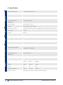
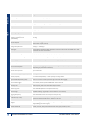
Specification ...............................................................................................................................................45
12
Contact Us ..................................................................................................................................................47
PENTAIR ENVIRONMENTAL SYSTEMS
MP SERIES SENSOR USER MANUAL
1
Introduction
1.1
System Description
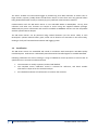
Thank you for purchasing a Greenspan MP Series Sensor (Model MP47 or MP65). This manual
provides a guide to the configuration, operation and maintenance of your sensor to provide long term
reliable and accurate monitoring.
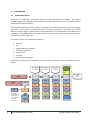
The Greenspan MP Series sensors provide a complete self-contained measurement and data logging
system for a wide range of environmental water monitoring applications. The sensors provide the
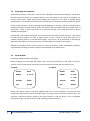
ability to measure single or multiple water quality parameters (up to 4 parameters on the MP47 and 6
parameters on the MP65) within the single sensor providing users the choice to select the parameters
which best suits their application.
Users have a choice of the following parameters:
•
Pressure
•
pH
•
Oxygen Reduction Potential
•
Electrical Conductivity
•
Temperature
•
Turbidity
• Optical Dissolved Oxygen
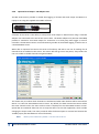
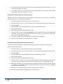
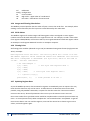
Customers can choose various combinations of parameters to measure. Options available are shown
below:
Inline Option
1
Choose 1 parameter
MP47
MP
Mount
MP65
ORP
OR
MP Mount
(on MP65 only)
Must choose
pH or ORP with
option of a
depth sensor
4
pH
Depth
Inline Option
2
Choose 1 parameter
Inline Option
3
Choose 1 parameter
Turbidity
Optical
DO
?
?
?
?
Depth
Depth
Depth
Depth
pH
pH
pH
pH
ORP
ORP
ORP
ORP
EC
EC
EC
EC
N/A
N/A
N/A
End Sensor
Choose 1
parameter
Ext Temp
N/A
PENTAIR ENVIRONMENTAL SYSTEMS
MP SERIES SENSOR USER MANUAL
The sensor includes an internal data logger to provide long term data collection at remote sites. A
large memory capacity (4 Mb) allows the MP Series Sensor to store data over long periods before
being downloaded either locally or remotely by your preferred communications method.
Communication with the MP Series Sensor is user selectable RS232 or RS422/485. Set up, data
collection and other user functions are simple to access using the supplied software package.
Additionally key sensor information and control is available via MODBUS. Sensors are also compatible
with the optional SDI-12 adapter.
The MP Series Sensor can be powered using external batteries (via the sensor cable) or with
Greenspan’s optional Lithium battery pack, which can be fitted as an extension to the sensor body,
making it a fully self-contained measurement and logging system.
1.2
Certification
The MP Series sensors are assembled and tested in accordance with Greenspan’s ISO 9001 Quality
Certified System. Each Sensor is individually manufactured and certified against a traceable Standard.
Following calibration the sensors undergo a range of additional control processes to ensure that all
specifications are consistent and documented.
•
•
•
5
The instrument is visually inspected, marked and labelled.
The complete sensor calibration record is archived for reference, and batch number
information is kept on file for statistical analysis.
An individual Certificate of Conformance is issued to the customer.
PENTAIR ENVIRONMENTAL SYSTEMS
MP SERIES SENSOR USER MANUAL
1.3
Unpacking and Inspection
All Greenspan sensors are made to order and are individually calibrated and inspected. This ensures
that they leave the factory in a working condition. They are packed in new cartons for shipping. On
receipt, the customer should inspect the packaging and contents for any signs of damage during
transportation. The customer should also check that all items on the delivery note have been received.
Please contact the factory in case anything has been damaged or missing. A full set of documentation
including Certificate of Conformance, Quick Start Guide, and User Manual will be provided with all
equipment – either in hard copy format or in electronic format on the USB flash memory device
shipped with the goods.
If fitted with a 316 Stainless Steel body, the unit should only be used in low EC situations. Care should
be taken against possible corrosion in high Chloride or Ferric solutions, water with high iron or
sulphate reducing bacteria, or low dissolved oxygen. The sensor can be fitted with an Acetal body
which provides superior corrosion protection in a wide range of chemically active waters.
Because an individual sensor may be used in a variety of locations, media compatibility should be
checked before installing and advice sought from Greenspan if any doubt exists.
1.4
Serial Number
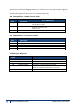
Checking the Model Number and Range
Before installing your Greenspan MP Series sensor, check the information on the label is correct to
confirm you have received the instrument you have ordered. The label will look similar to this.
For MP47:
For MP65:
MODEL
MP47
MODEL
MP47
RANGE
0 – xx M
RANGE
0 –14pH
0 - xx M
OUTPUT
RS232
OUTPUT
RS232
S/N
012345
S/N
012345
Please note, where sensors have been supplied with two or more parameters, the range of each
parameter will be noted on the serial number label. The ranges may be listed in no specific order. The
customer is advised to keep a record of the serial numbers in case the sensor is lost or damaged.
Greenspan keeps records of all sensors sold including a calibration history.
6
PENTAIR ENVIRONMENTAL SYSTEMS
MP SERIES SENSOR USER MANUAL
1.5
Warranty Policy
Greenspan warrants all new Greenspan products against defects in materials and workmanship for 12
months from the date of invoice.
Products that prove to be defective during the warranty period will be repaired or replaced at the
discretion of Greenspan.
Under Greenspan warranty conditions; it is the responsibility of the customer to cover shipping
charges back to the factory. Upon repair/replacement Greenspan will cover the return shipping
charges to the customer.
This warranty does not apply to products or parts thereof which have been altered or repaired outside
of the Greenspan factory or other authorised service centre; or products damaged by improper
installation or application, or subjected to misuse, abuse neglect or accident. This warranty also
excludes items such as reference electrodes and Dissolved Oxygen membranes that may degrade
during normal use.
Greenspan will not be liable for any incidental or consequential damage or expense incurred by the
user due to partial or incomplete inoperability of its products for any reason whatsoever or due to
inaccurate information generated by its products.
All Warranty service will be completed as soon possible. If delays are unavoidable customers will be
contacted immediately.
Any sensor should not be dismantled unless under instruction from Greenspan Service staff. Incorrect
handling will void the warranty.
1.6
Factory Service & Repair
The correct choice of sensor and assistance with field installation can be provided by Greenspan and
their sales offices. A correct choice of equipment, together with technical advice and field experience
should result in long term success in the field. Greenspan Technical Services is dedicated to customer
support and provides assistance in the selection, installation, deployment and commissioning of
sensors with a full range of consulting services. All Greenspan products are designed, developed and
manufactured in Australia and can be supplied at short notice.
If for some reason sensors are required to be returned to our factory or your sales representative,
please note the model and serial number, describe the problem, including how and under what
conditions the instrument was being used at the time of malfunction. Clean the product and cable.
Decontaminate thoroughly if used in toxic or hazardous environment. Carefully pack product in
original packaging if possible & include a statement certifying product and cable have been
decontaminated with supporting information. Products returned for repair must be accompanied by a
completed GRN (Goods Return Notification) form. All sensors returned for service and repair work
must be properly decontaminated prior to return. A cleaning charge may be applied to sensors that
require further decontamination. Service work will not commence until the quotation has been
accepted by the customer. A purchase order for all repair and service work will be required before
work is carried out.
7
PENTAIR ENVIRONMENTAL SYSTEMS
MP SERIES SENSOR USER MANUAL
2
Sensor Overview (by Parameter)
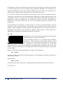
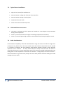
2.1
Pressure
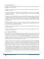
The pressure sensor utilizes a ceramic-based, capacitive element as the
transducer. This is designed to be of rugged construction and
incorporates active electronics as an integral part of the transducer
substrate to enhance reliability and accuracy. Force applied to the
ceramic element, due to the pressure, deforms its shape. This deformation causes a change in
capacitance which can be measured by the electronics. The inherent stability and toughness of the
ceramic ensures the repeatability and long term accuracy of the readings are maintained under the
harshest field conditions.
The on-board microprocessor converts the transducer output voltage to a 24 bit digital signal and also
measures the transducer temperature. This information is used to temperature compensate the
sensor over the range 0 - 50°C. Both pressure and temperature are displayed in SensorMate in real
units i.e. metres of depth and degrees centigrade.
Benefits of the ceramic capacitance sensors over other types of sensors are:
•
•
•
•
•
•
•
•
•
2.1.1
Extremely high overload limit (typically up to 10 X overload protection)
Absolute resistant to wear
High temperature stability
Excellent Long term stability
Excellent Repeatability and linearity
No hysteresis effects normally associated with strain type sensors
Corrosion resistant – Other sensors require contact of stainless steel face
Not subject to mechanical fatigue that may affect strain gauge type sensors
Low power consumption suitable for remote monitoring & control units
Absolute or Gauge
Gauge sensors are vented to atmosphere so that the effects of changes in barometric or atmospheric
pressure do not affect water level readings. Sensors that are not vented to atmosphere are referred
to as Absolute Sensors. The primary difference between the two types of sensors is the effect of
atmospheric pressure on the water level measurements they provide.
Barometric Pressure acts on both sides of a Gauge sensor (i.e. via the water on one side and via the
vent tube on the other). The Barometric pressure is cancelled out and has no effect on the water level
readings. Gauge Sensors will read zero in air.
Barometric atmospheric pressure acts only on one side of a non-vented or Absolute Sensor (on the
water side). Any changes in Atmospheric pressure will be detected by the sensor and measured as
changes in water pressure. As the Barometric pressure varies, these changes will be measured as
water level changes even though the actual water level may have remained steady. Typical variations
in barometric pressure when converted to head of water are in the order of +/- 100mm. A large
change in weather pattern (storm front) may cause a drop in barometric pressure by up to 20Hpa
8
PENTAIR ENVIRONMENTAL SYSTEMS
MP SERIES SENSOR USER MANUAL
which would cause an error of 200mm. Water level variations caused by barometric pressure can be
removed by monitoring barometric pressure (e.g. via a weather station or barometric sensor) and then
post processing the absolute water level readings.
The lowest, standard absolute range offered is 20m, which is suitable for measuring water levels of up
to approximately 10m. Absolute sensors will read zero in a perfect vacuum and around 10m in air
depending on the atmospheric pressure.
Gauge sensors are suitable for most monitoring applications where water level readings are required.
Absolute sensors are suitable for applications where a vented cable is not desirable (e.g. Battery pack
only sensors).
2.1.2
Moisture Ingress
To avoid moisture ingress via the vent tube on any sensor configuration with gauge pressure sensors, a
closed vent system is provided which maintains atmospheric pressure within the ceramic capacitance
transducer while preventing moisture condensing within the sensor cable.
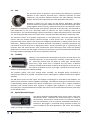
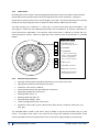
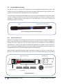
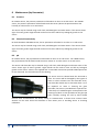
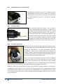
2.2
Electrical Conductivity (Toroidal Sensing Head)
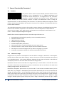
The EC sensor uses an electromagnetic field for measuring
conductivity. The black plastic head contains two coils wound on
toroidal (i.e. doughnut shaped) ferrite cores. The hole in the EC
head passes through the centre of the coils. One Coil is excited
with an alternating current which generates an electromagnetic
field around the coil and into the water. Special electronics senses the amount of electromagnetic field
in the second coil which is proportional to the conductivity of the water that fills the hole and
surrounds the head.
The main benefit derived from utilising toroidal sensing technology for the measurement of EC is the
reduction in fouling and the elimination of system errors caused from electrode degradation. There
are no electrodes in direct contact with the water that can foul, erode or corrode. The sensor head
should be periodically inspected and cleaned with fresh water and damp cloth. The protective shroud
is easily unscrewed from the head for quick access. Bottle brushes are commonly used for cleansing
the sensor hole. In marine environments crustaceans may need removal at regular intervals.
The toroidal sensors create a magnetic field around the sensing head. The standard EC sensor includes
a shroud around the transducer head that constrains this field and allows the sensor to be deployed
close to other objects. The sensor head should always be completely submerged and positioned such
that the possibility of air bubbles becoming entrapped within the sensor hole is minimised. Large
bubbles may cause errors if trapped.
Electrical Conductivity (EC) is the measurement that indicates the ability of a solution to carry an
electric current. It is defined as the inverse of resistance (Ohms) per unit square and is measured in
units of Siemens/metre or micro-Siemens/centimetre.
9
PENTAIR ENVIRONMENTAL SYSTEMS
MP SERIES SENSOR USER MANUAL
EC readings are a function of the number of ions present and their mobility. The electrical conductivity
of a liquid changes due to the ion mobility being temperature dependant. The temperature coefficient of conductance (or the K factor) varies for different salts and can be in the range 0.5 to 3.0. A
default value of 1.84% per degree Centigrade is used in the MP Series sensors.
EC is a function of both salt concentration and temperature, and its value can be expressed as nonnormalised or normalised. The non-normalised (Raw) reading will vary with temperature even if the
concentration of salt in the liquid does not change. Normalisation automatically compensates for
temperature variations providing the salt concentration remains the same. Normalisation is
referenced to 25°C which means that the raw and normalised readings are identical at this
temperature.
The measurement of conductivity is usually carried out to assist in the determination of the salt
content of a water body (the salinity). The MP Series sensor calculates a salinity value, based on
method “2530-D, Algorithm of Practical Salinity” (Standard Methods for the Analysis of Water and
Wastewater). This method is also contained in “UNESCO Technical papers in marine science 44 –
Algorithms for computation of fundamental properties of seawater.”
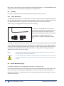
2.3
pH
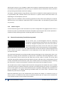
The PH sensor uses a robust, gel filled, industrial pH electrode for
field monitoring in a variety of environments.
The pH electrode consists of a PH sensitive glass membrane
attached to a sealed insulating tube containing a solution of fixed
PH in contact with a silver-silver chloride half cell. The potential
developed across the membrane is compared to a stable reference potential e.g. a silver-silver
chloride half-cell in contact with an electrolyte containing chloride. Completion of the circuit is by
means of a porous constriction (the salt bridge) which allows the reference electrolyte to slowly flow
into the sample.
pH gives an indication of the acidity/alkalinity of a solution and is defined as:
pH = - log (H+)
and covers a scale from 0 (acid) to 14 (alkaline) where H+ is the hydrogen concentration in solution, at
ordinary temperatures.
E.g. pH of water
H2O = H+ +OHThe concentration of each type of ion is 10-7gm molecule/litre and hence the pH of pure water is:
pH = -log 10-7= 7
10
PENTAIR ENVIRONMENTAL SYSTEMS
MP SERIES SENSOR USER MANUAL
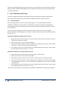
2.4
ORP
The principle means of detection is by measuring the difference in potential
between an inert indicator electrode and a reference electrode. At redox
equilibrium, the potential difference between the ideal indicator electrode
and the reference electrode equals the redox potential of the system.
Reactions involving ions are both pH and Eh(mV) dependent, therefore
chemical reactions in aqueous media can often be characterised by pH and Eh
acting together with the activity of dissolved chemicals. The MP Series sensor
probe uses a combination, Platinum ORP and reference electrode in the one body. This electrode is
field replaceable by the user. Electrodes made of platinum are most commonly used for Eh
measurements. The standard hydrogen reference electrode is fragile and impractical for routine field
use. The Greenspan ORP sensor uses a silver:silver- chloride electrode and these are commonly used.
The reference consists of a specially coated wire in a salt filled cavity. This cavity makes electrical
contact with the outside aqueous solution through a small porous wick. A common cause for
premature ORP sensor failure is the chemical or biological contamination or fouling of the wick or salt
filled cavity. Added protection for the reference electrode is provided by a reference protection ring
constructed of porous PTFE that is impregnated with a special conductive gel. It is placed over the
reference wick and should prevent most contaminants from reaching the wick, while still allowing
good electrical contact with the sample. If the low cost protection ring is contaminated or fouled it can
be simply replaced, extending the life of the combination electrode.
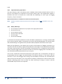
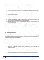
2.5
Turbidity
Turbidity is the measurement that indicates the clarity of water due to fine
suspended particles. In the environment, turbidity is often due to clay or
silt. These fine particles have the ability to scatter light. The MP Series
sensor has a light source that is projected into the water. A detector
measures the light that has been scattered at 90 degrees to the source. As
the number of particles increase, more light is scattered and sensed by the
detector and the higher the turbidity reading.
The Turbidity probes, with their integral wiper assembly, are designed where bio-fouling or
sedimentation build-up is possible. The probes may be submerged to a depth of 100 meters (approx.
330 feet).
The MP Series sensors use 90° optics and employs infrared light in accordance with ISO7027. The
optical system transmits a beam of 860nm wavelength. The effective working area around the sensor
is approximately 50mm forward and 50mm circumference. The sensor uses a unique modulation
technique that ensures almost total rejection of ambient light conditions as well as a unique
microprocessor controlled differential sample and hold circuit for enhanced performance particularly
at low turbidity levels.
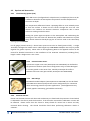
2.6
Optical Dissolved Oxygen
The optical dissolved oxygen (ODO) sensor uses a robust, solid state,
fluorescence based transducer for field monitoring in a variety of
environments. Fluorescence based sensors are inherently reliable
and low maintenance, with no need for replaceable membranes or
electrolyte. No Oxygen is consumed during operation making the
sensor suitable for low flow applications. The sensor also responds
quickly to changes in Oxygen levels.
11
PENTAIR ENVIRONMENTAL SYSTEMS
MP SERIES SENSOR USER MANUAL
2.6.1
Principal of Operation
•
The emitter sends light, at ~475 nm, to the back side of the sensing element.
•
The wetted side of the sensing element consists of a thin layer of a hydrophobic sol- gel
material. A ruthenium complex is trapped in the solgel matrix, effectively immobilized and protected
from water.
•
The light from the LED excites the ruthenium complex immobilized in the sensing element.
•
The excited ruthenium complex fluoresces, emitting energy at ~600 nm.
•
If the excited ruthenium complex encounters an oxygen molecule, the excess energy is
transferred to the oxygen molecule in a non-radiative transfer, decreasing or quenching the
fluorescence signal (see Fluorescence Quenching below). The degree of quenching correlates to the
level of oxygen concentration in contact with the sensing element.
2.6.2
Fluorescence Quenching
Oxygen is able to efficiently quench the fluorescence and phosphorescence of certain luminophores.
This effect (first described by Kautsky in 1939) is called "dynamic fluorescence quenching." Collision
of an oxygen molecule with a fluorophore in its excited state leads to a non-radiative transfer of
energy. The degree of fluorescence quenching relates to the frequency of collisions, and therefore to
the concentration of the oxygen- containing media.
12
PENTAIR ENVIRONMENTAL SYSTEMS
MP SERIES SENSOR USER MANUAL
3
Applications
Applications in which the Greenspan MP Series sensors can be used include:
•
•
•
•
•
•
•
•
13
Monitoring of streams and rivers.
Monitoring of water storage bodies including stratification studies.
Intermediate and final effluent treatment monitoring.
Hydrological run off studies.
Ground and bore water analysis.
Drinking water filtration efficiency.
Industrial process monitoring.
Sludge and dredge monitoring.
PENTAIR ENVIRONMENTAL SYSTEMS
MP SERIES SENSOR USER MANUAL
4
Instrument Details
4.1.1
Sensor Design
The Greenspan MP65 Sensor consists of the following primary elements:
MP Sensor mount
(houses field replaceable pH electrode)
Double O-ring sealing
Power and Data Cable
Moulded cable entry
End Sensor
Optional Inline Parameter
(up to 2)
65mm OD 316 SS or Acetal sensor body
containing microprocessor controlled electronics
The Greenspan MP47 Sensor consists of the following primary elements:
Optional Inline Parameter
(up to 2)
Double O-ring sealing
Power and Data Cable
Moulded cable entry
End Sensor
14
PENTAIR ENVIRONMENTAL SYSTEMS
47mm OD 316 SS or Acetal sensor body
containing microprocessor controlled electronics
MP SERIES SENSOR USER MANUAL
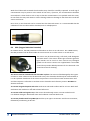
4.1.2
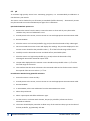
Cable Details
All Greenspan sensors utilise a specially designed Polyurethane Cable. The cable is reinforced with
Aramid fibres which provide superior tensile strength and low stretch properties. Changes in
temperature have little effect on the overall length of the cable. This feature provides users with the
benefit of self-suspending the sensor to depths of 300m without additional strain relief.
The cable contains 12 x conductors, 1 x drain wire, an internal vent tube and Aramid fibres. The
outer jacket is made from UV stabilized Polyurethane and is suitable for all external, underwater or
harsh environment applications. This common cable construction is utilized for vented and nonvented Greenspan sensors. Cables are generally factory fitted at time of manufacture in specified
lengths.
Cable Construction
7
6
5
1 –Vent Tube: Polyamide
(size ID x OD) 2.40 x 3.20 mm
2 – Aramid Fibre
2
3 - 12 x Conductors
7 x 0.20 mm Tinned Copper
Section = 0.22mm2 AWG24
Insulation: Polypropylene
(size) = 1.10 mm ± 0.05 mm
3
4 - Tape: Polyester
1
5 – Drain Wire: 7x0.20 TinCu
4
6- Tape: Polyester Aluminium
7 - Jacket: Polyurethane black,
(size OD) 8.05 mm ± 0.15
6
4.1.3
•
•
•
•
•
•
•
•
•
•
Mechanical Specifications
Specially manufactured Greenspan cable with 12 cores and internal vent
High chemical resilience and abrasive resistance
Conductor cross section : AWG 24,
Electrical Resistance 9 ohm per 100m (per conductor)
Operating temperature: 85°C (max.),
Bending radius (static) : 6 ,
Bending radius (dynamic) 12.
Max Operating voltage : 250V
Jacket Printing (white colour each meter)
Conductor colour codes : green, yellow, white, black, brown, turquoise, violet, pink, red,
blue, grey
The moulded cable is fitted to the sensor using a double o ring seal and located using 2 x grub
screws. The length of the cable is not critical to the long term calibration and operation of the
sensor (provided the electrical requirements such as minimum supply voltage are maintained).
15
PENTAIR ENVIRONMENTAL SYSTEMS
MP SERIES SENSOR USER MANUAL
4.2
4.2.1
Options and Accessories
Closed Venting System (CVS)
When MP sensors (configured with a depth sensor) are deployed, there can be
a difference between the atmospheric temperature and the temperature of
the sensor at depth.
This temperature differential causes a pumping effect to occur whereby moist
air from the surface is drawn into the sensor through the vent line. This
moisture can condense on sensitive electronic components due to warm
surface air cooling inside the sensor.
Sealing the system against exposure to the atmosphere and conditioning the
existing air in the vent tube can alleviate this problem. Silica desiccant crystals
easily absorb moisture thereby drying the air and are used in the closed loop
venting system 7CVS-001.
For all gauge (vented sensors) a Closed Vent System must also be fitted (pictured left). A single
7CVS-001 is designed to handle sensor cable lengths up to 70 metres. Multiple units may be joined
together for greater capacity. Please refer to the Engineering Note in the appendix section on the
manual for detailed instructions on the installation of the 7CVS-001. Dimensions (including filter):
length x width x height 16cm x 7cm x 5cm.
4.2.2
Protective Nose Cones
A protective copper nose cone (Greenspan Part # 492-0241) can be fitted to
the pressure transducer (end sensor configuration only) to inhibit biological
or marine growth on the sensor face. Similarly Greenspan also offer a
stainless steel nose cone (pictured left, Greenspan Part # 492-0246)
4.2.3
BSP Fittings
Brass BSP threaded adaptors (Greenspan Part # 492-0238) can also be fitted
to the MP Series Sensor (end pressure sensor configuration) for connection
when monitoring pressure in process applications. (Such applications may
include, pipeline monitoring, gas bubblers and tanks).
4.2.4
EC Sensor Shroud
Please note that MP sensors with electrical conductivity are fitted with the protection shroud which
is calibrated in the factory with the shroud on. If the shroud is removed the calibration in water will
be affected. Please ensure that the shroud is always fitted for normal use in water and only
removed whilst cleaning. The shroud should be fitted when performing calibration checks in
solutions.
16
PENTAIR ENVIRONMENTAL SYSTEMS
MP SERIES SENSOR USER MANUAL
If the sensor needs to be deployed without a shroud this requirement should be noted at time of
order. The factory can then perform a special calibration without a shroud using large volumes of
standard solutions. On deployment it is necessary to maintain a space of at least 100mm (4”) around
the head.
4.2.5
Cable Options
A standard sensor is supplied with a fixed moulded cable entry and a 7 pin Hirschman connector at
the end of the cable opposite to the sensor. The length of cable is specified by the user.
4.2.6
Sensor Body
Sensor is available with a black Acetal or passivated 316 Stainless Steel body. For applications in
harsh environments it is recommended that the Acetal body material be specified.
4.2.7
Communication Cables
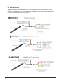
A communication cable is required to connect the sensor to a PC.
17
•
5CC-840: The standard cable has a 7 socket Hirschman connector on one end and a USB on
the other end. For connection to PC and laptops via USB port.
•
5CC-700: Has a 7 socket Hirschman connector on one end and DB9 on the other end. For
connection to PC and laptops via serial ports.
•
5CC-750: Has a 7 socket Hirschman connector on one end and bare wires on the other end.
For connection to TLC, dataloggers etc.
•
5CC-102: Has a 9 pin Conxall to D connector for serial ports. To connect a sensor with
battery pack only to a PC or laptop via a serial port.
PENTAIR ENVIRONMENTAL SYSTEMS
MP SERIES SENSOR USER MANUAL
4.2.8
Optional Serial Output – SDI Adapter Unit
The MP Series Sensor provides on board data logging of all data and serial output via RS232 to a
Laptop or PC using the supplied SensorMate software.
A feature of the sensor is the ability to also provide serial output in SDI12 format using a small SDI
Adapter unit connected to the end of the sensor cable. The SDI12 Adapter unit (Part No 7SDI-1000)
provides a standard 3 wire SDI12 output for connection to a third party Data Logger or Process
Controller. The MP Series Sensor can simultaneously provide on-board data logging, as well as act as
a standard SDI12 sensor.
When data is requested via SDI-12 the sensor will wake up and take a new set of readings for all
channels that are enabled in the sensor. The sensor will then go into a low power, sleep mode. The
user can enable or disable channels using SensorMate.
The easiest way to confirm which channels are enabled and what order the data will be returned via
SDI-12 is to view the SensorMate monitor screen. By default, the data returned via SDI-12 will be
the same channels and in the same order as what is displayed in the SensorMate monitor screen.
Special SDI-12 commands allow the user to setup the SDI-12 to suit their application, which include
changing the output order, how many numerals after the decimal point is returned and activate the
Turbidity wiper (See SDI-1000 user manual for detail).
NOTE:
18
Memory Used and Memory Used % is not returned via SDI-12.
PENTAIR ENVIRONMENTAL SYSTEMS
MP SERIES SENSOR USER MANUAL
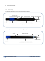
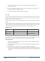
4.3
On Board Battery Housing
The MP Series Sensor may be factory fitted with a non-rechargeable long-life battery pack. This
enables the sensor to be deployed at remote sites completely independent of above surface power
supplies (no cable connection) and allows for discreet applications.
It also functions as a backup power supply in the event of a surface disturbance to the main supply.
The unit is designed to allow easy access to the battery compartments for battery changeover and is
housed in a cylindrical body of approximately the same dimensions as the sensor housing, thus
doubling the length of the sensor.
Battery Pack (Cover Removable)
Sensor
Sensor with Battery Pack Cover Ready to Deploy
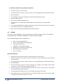
4.3.1
Battery Replacement
Batteries are removed by unscrewing the housing cover, as indicated below and gently levering the
battery cells until they slip out. Replacement batteries must be inserted correctly or damage to
batteries may occur. Align the +ve on the battery cells with the red indicator on the housing and
push batteries in. Batteries are subject to leakage after depletion. The leakage is Thionyl Chloride, a
toxic, corrosive non-flammable liquid that can cause damage to equipment and personal injury if in
contact with the skin or eyes. Please replace batteries when depleted.
When installing replacement batteries within the battery housing it is necessary to push firmly on
the cover until it clicks home over the O rings, after this it can be easily tightened on the thread by
Battery Pack Housing
Batt Pack Cover
+
+
Screw on Housing
+
+
Top View, showing 3 x 3
lithium AA batteries
9 x AA lithium
Optional Battery Pack
19
PENTAIR ENVIRONMENTAL SYSTEMS
MP SERIES SENSOR USER MANUAL
hand.
4.3.2
Important Battery Information
The type of battery used in the battery pack is Li/Mn02, Lithium Thionyl Chloride 3.6V AA cells. A
total of nine batteries are required for each sensor battery pack. This configuration supplies a
maximum 10.8 volts at 5.2A/Hr and a useful field life, depending on sensor type and logging
frequency, of up to 12 months.
Replacement batteries are available from Pentair Environmental Systems.
Note: Standard AA lithium batteries (Duracell or Energiser Type) are NOT suitable for use in the
sensor.
4.3.3
•
•
•
•
•
•
Battery Warnings:
Do not dispose of batteries in fire, dispose of in appropriate manner.
Do not short circuit
Do not expose to water
Do not crush or puncture
Do not charge
Do not over-discharge
To maintain the maximum possible life of the cells before replacement it is strongly recommended
that an external power supply is connected to the sensor when downloading data. The power drawn
when downloading is at its greatest level, therefore battery depletion will be much more rapid.
Battery life will depend on the battery type as well as the frequency of logging. Connection to a
computer will drain the battery supply more quickly due to the higher current imposed by the RS232
serial data communications and will considerably reduce battery life. An additional internal lithium
battery maintains logger data at all times but does not sustain the logging state. This battery is not
user accessible and will maintain data for up to 10 years.
If the sensor is fitted with on board internal battery pack option and is to be placed in storage it is
recommended that the logger be powered down and lithium batteries in the battery pack be
removed. To turn off the logger after exiting from SensorMate, disconnect the communications
cable and unscrew the battery cover. This exposes the battery compartment to allow removal of the
batteries. Removing power will not affect any data remaining in storage so sensors could be
downloaded away from the site if required.
20
PENTAIR ENVIRONMENTAL SYSTEMS
MP SERIES SENSOR USER MANUAL
4.4
Sensor Factory Calibration
Pressure & EC Sensors:
•
The sensor is assembled and calibrated to the required range using Ruska Digital Pressure
controllers which are externally calibrated in NATA certified laboratories.
•
Any sensor with EC or pressure parameters is placed in an environmental chamber and
subjected to a matrix of temperature and pressure and EC inputs. A typical calibration
collects data for each individual sensor at 6 pressure inputs (0, 20, 40, 60, 80, and 100 %FS)
and 11 EC inputs (0, 10, 20, 30, 40, 50, 60, 70, 80, 90 and 100 %FS) at 6 temperatures (0, 10,
20, 30, 40 and 50 deg C).
•
A unique calibration curve, for the transducers and electronics set, is calculated from this
data and loaded into the sensor.
•
The sensor is then re-run through the environmental chamber to ensure that the calibration
curves are correct over the entire working range and the sensor meets specifications.
pH Sensors:
•
•
Sensors are calibrated using a stable, precision DC source.
The sensor with electrode fitted is checked in pH 4.0, 6.0 & 10.0 buffer solutions which are
verified against external pH buffer solutions checked in a NATA accredited facility.
ORP Sensors:
• Sensors are calibrated using a stable, precision DC source.
• The sensor with electrode fitted is checked in Zo Bells Standard solution
Optical DO Sensors:
•
Sensors are calibrated in a stirred, aerated DI water bath for 100% saturated and an aqueous
Sodium Sulphate solution for zero.
Turbidity Sensors:
•
Sensors are calibrated using AMCO CLEAR® TURBIDITY STANDARD, for ANALITE ISO 7027
PROBES.
All Sensors:
• An extensive range of final calibration and inspection tests, including tests in solutions of
known standards, are carried out on every sensor.
21
•
The sensor is visually inspected and packed ready for despatch.
•
The complete calibration records, sensor history and batch number are placed on file and
archived.
•
The sensor is visually inspected and packed ready for despatch.
PENTAIR ENVIRONMENTAL SYSTEMS
MP SERIES SENSOR USER MANUAL
5
Sensor Wiring & Connections
5.1
Standard Connections
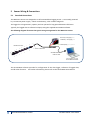
The MP Series sensors are designed as a self-contained data logging sensor. It is normally powered
by a 12-24V DC power supply – which can be battery, solar or Mains Plug Pack.
The logger has a large memory capacity and can operate for long periods between field visits.
Typically the logged data is collected via laptop using the supplied SensorMate software.
The following diagram illustrates the typical wiring arrangement for the MP Series Sensor.
Ground (-ve Supply) black
9-30VDC (+ ve Supply) red
Shield (Gnd) green/yellow
MP Series Sensor
Sensor cable with
5CC-840 USB Comms
Cable for HS7
PC or laptop running
SensorMate Software
The SensorMate software provides for configuration of the data logger, collection of logged data,
and all other functions. For further information, please refer to the SensorMate User Manual.
22
PENTAIR ENVIRONMENTAL SYSTEMS
MP SERIES SENSOR USER MANUAL
5.2
Wiring Diagrams
A Breakout Communication Cable (Part # 5CC-750) is available if a bare wire connection is more
suitable for an application. The Pentair MP Sensor CommsMode Utility contains wiring information
for the various modes of serial communication.
23
PENTAIR ENVIRONMENTAL SYSTEMS
MP SERIES SENSOR USER MANUAL
6
Serial Communication (RS232, RS422/485)
Communication to the MP series sensors is via a serial link. The user can select RS232 (default
setting) or RS422/485. The Pentair MP Sensor CommsMode Utility is a software tool that provides a
simple method for selecting communication modes, non-standard baud rates and Modbus settings.
NOTE: SensorMate software uses the default settings.
NOTE: Full Duplex, where data is sent and received at the same time, is not supported.
24
PENTAIR ENVIRONMENTAL SYSTEMS
MP SERIES SENSOR USER MANUAL
6.1
Waking sensor
MP Sensors are designed to wake on receiving any commands on its communication lines. Although
it wakes quickly, it may miss the first few characters of a command. Most generic Modbus
communication programs will re-try if no valid response is received so this usually causes no
problems. All in house programs send a “Null” command to wake the sensor prior to any
subsequent commands.
Communication circuits will switch to a low powered, listening mode (sleep) if there has been no
communication activity for 60 seconds.
25
PENTAIR ENVIRONMENTAL SYSTEMS
MP SERIES SENSOR USER MANUAL
7
Field Deployment Considerations
For applications in harsh environments it is recommended that the optional Acetal casing be
specified.
The sensor head should be periodically inspected for fouling, and can be cleaned with fresh water
and damp cloth. In marine environments crustaceans may need removal at regular intervals.
The body should always be fully immersed under the water to ensure the electronic module is at
water temperature and to avoid any possible anodic/cathodic action taking place on the stainless
body due to the oxygen difference across the boundary.
Care should be taken if clamps are to be attached to the Stainless Steel body as the depletion of
oxygen to the clamp/probe interface can cause corrosion due to anodic/cathodic action. It is
recommended that Acetal body sensors be used if clamping.
Sensors should generally be installed such that they can be easily and safely removed for cleaning,
servicing. For environmental applications the sensor can often be mounted inside a section of PVC
or steel pipe which enters the water body. The sensor can then be slid down inside the pipe until
the sensor head just protrudes into the water body. This provides a high degree of protection for
the sensor from environmental (sunlight, heat, flood debris etc) as well as from other influences
such as Cattle, vandalism etc. Most sediment transport occurs during storm events and flood
conditions. Protection from floating debris damage is an important consideration along with
adequate tethering of sensors.
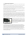
The MP sensor (with pH or ORP) is shipped with a rubber
cap covering the electrode. This cap contains a small
amount of 3M KCl solution and is in place to prevent the
electrode from drying out during shipping and storage. This
cap must be removed prior to installation. The cap should
be retained so that it can be placed back on the electrode if
the sensor is to be removed.
7.1
Cabling Considerations
Care should be taken with installation and field servicing to ensure the cable is not subjected to
persistent pulling snagging or severe compression. Cyclic loading of the cable should also be avoided
through careful sensor deployment. Additional stilling wells or mounting brackets may be required
to prevent sensor movement which may cause long term cable movement. Where cable runs are
required which may be subject to environmental effects (heat, water movement, sunlight, flood
debris etc.) it is advisable to protect the sensor cable inside a slightly larger diameter conduit such as
PVC, steel or polyethylene. This also allows the sensor cable to be pulled out – should a sensor
change-over be required at the site. Maximum cable runs up to several hundred meters are possible
without affecting electrical signals.
26
PENTAIR ENVIRONMENTAL SYSTEMS
MP SERIES SENSOR USER MANUAL
7.2
Typical Sensor Installations
•
Edge of river/stream/lake embankment.
•
Mounted within a stilling well off stream from main flow.
•
Mounted within drainage channels/pipes.
•
Suspended from dam walls.
•
Sensor anchored to bed of lake/stream.
7.3
Field Installation must ensure:
•
•
•
7.4
The sensor is anchored or held in position or located so it is not subject to any movement
during normal operations.
Sensor is protected from direct sunlight to avoid high temperature fluctuations
Sensor is protected against high turbulence and possible debris loading during flow events
Other Considerations
Environmental compatibility should be checked before using the sensors and advice sought from
Greenspan if any doubt exists. The sensor utilises some 316 stainless components that are suitable
in a majority of situations but care should be taken against possible corrosion in high Chloride,
Sulphate or Ferric solutions. The body should always be totally immersed under the water to
ensure that the sensor is at water temperature and to also avoid any possible anodic/cathodic action
taking place on the components at the water-air interface. If using clamps to mount the sensor –
these should be of a type that evenly clamps the sensor body without excessive loading that could
damage the sensor body.
27
PENTAIR ENVIRONMENTAL SYSTEMS
MP SERIES SENSOR USER MANUAL
8
Maintenance (by Parameter)
8.1
Pressure
On a MP47 sensor, the pressure parameter will be either an inline or an end sensor. On a MP65
sensor, the pressure parameter will be fitted inside the sensor (where the pH electrode is also
housed), an inline sensor or an end sensor.
The sensor may be cleaned using a soft cloth, mild detergents and warm water. If the sensor shows
signs of marine growth a light biocide can be used to clean and kill any biological growth on the
sensor.
8.2
Electrical Conductivity
On both the MP47 and MP65 sensor, the EC parameter will either be an inline or an end sensor.
The sensor may be cleaned using a soft cloth, mild detergents and warm water. If the sensor shows
signs of marine growth a light biocide can be used to clean and kill any biological growth on the
sensor.
8.3
pH
On a MP47 sensor, the pH parameter will be either an inline or an end sensor. On a MP65 sensor,
the pH parameter will be fitted inside the sensor mount as an inline sensor or an end sensor.
The sensor and electrode may be cleaned using a soft cloth, mild detergents and warm water. If the
sensor shows signs of marine growth a light biocide can be used to clean and kill any biological
growth on the sensor. Sensors are supplied with a removable shroud that provides added protection
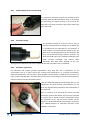
for the electrode. This shroud unscrews for cleaning.
The sensor must be cleaned with the electrode in
place. The sensor will be damaged by the ingress of
water or other solutions into the electrode cavity.
The electrode should only be removed when it is to
be replaced. To assist in cleaning the glass
electrode, the sensor is provided with a special tool.
A few drops of a mild detergent can be placed in the
cleaning tool which is then pushed over the glass pH
bulb. Carefully rotating the tool by hand should
remove most contamination. For heavy scaling or contamination a cleaner that contains some
abrasive can be used. Rinse the electrode in clean water prior to installing sensor or checking
calibration.
28
PENTAIR ENVIRONMENTAL SYSTEMS
MP SERIES SENSOR USER MANUAL
8.3.1
Replacing Reference Protection Ring
The reference protection ring can be removed and/or
replaced (with the electrode still in place in the sensor)
by unscrewing the plastic shroud on the end of the
electrode. The white protection ring can be slid off the
glass electrode.
8.3.2
Electrode storage
PH electrodes should be stored in such a way to
prevent the electrode from drying out. A rubber cap
is provided with the electrode for this purpose. A
small amount of liquid should be placed in this cap
prior to the cap being placed over the electrode. 3M
KCl is the preferred storage solution however; tap
water should be used if not available. Soaking in pH 4
buffer solution overnight may restore some
electrodes that have been allowed to dry out,
although some calibration drift can be expected until the electrode is fully re-hydrated.
8.3.3
Electrode replacement
PH electrodes will require periodic replacement. How long they last is dependent on the
environment and to a lesser extent the cleaning and maintenance. In a typical environment,
electrode life between 1 and 3 years is quite possible. The electrode is sealed in its mount with 2 o
rings on the electrode body. The electrode is removed by unscrewing it from the housing. Spanner
flats are machined on the electrode to assist.
Take care when handling the pH electrode, that it is not
handled by the gold contacts. Contamination of this
area may degrade the performance and expected life of
the electrode
Prior to removal of an electrode the sensor must be
thoroughly cleaned and dried. Care must be exercised
to ensure that no liquids or other contaminants enter
the electrode cavity. The pH sensor should not be
stored or transported without an electrode. Immersion
of a PH3000 without an electrode will likely cause
damage to the sensor.
29
PENTAIR ENVIRONMENTAL SYSTEMS
MP SERIES SENSOR USER MANUAL
With the old electrode removed the electrode cavity should be carefully inspected. A small ring of
contamination may be present at the mouth of the cavity. If present, this contamination should be
removed with a clean cloth in such a way so that the contamination is not pushed inside the cavity.
Do not flush the cavity with water or other cleaning solvents as damage to the electronics inside the
sensor could occur.
Once clean, a new electrode can be screwed into the electrode mount. It is recommended that the
calibration of the new electrode be checked prior to re-deployment.
8.4
ORP (Oxygen Reduction Potential)
On a MP47 sensor, the ORP parameter will be either an inline or an end sensor. On a MP65 sensor,
the ORP parameter will be fitted inside the sensor mount as an inline sensor or an end sensor.
The sensor may be cleaned using a soft cloth, mild detergents
and warm water. If the sensor shows signs of marine growth a
light biocide can be used to clean and kill any biological
growth on the sensor. Sensors are supplied with a removable
shroud that provides added protection for the electrode. This
shroud unscrews for cleaning.
The sensor must be cleaned with the electrode in place. The sensor will be damaged by the ingress
of water or other solutions into the electrode cavity. The electrode should only be removed when it
is to be replaced. Cleanliness of the sensor and junction is critical for accurate measurement. Drift
and slow response is often due to unclean sensor electrodes and reference junction. DO NOT use
abrasive materials.
To remove inorganic deposits and scale: Soak sensor electrode in dilute KCl for an hour. Wash well
with water and condition in 20% KCl solution before use.
To remove solids and organics Wipe the sensor electrode with cotton or tissue soaked in mild
non‐alkaline detergent. Wash with water and condition in 20% KCl before use.
To remove plated metals from ORP Tips Soak the tip in approx. 0.1M nitric acid for 15‐20 minutes,
followed by conditioning in 20% KCl.
30
PENTAIR ENVIRONMENTAL SYSTEMS
MP SERIES SENSOR USER MANUAL
8.4.1
Replacing Reference Protection Ring
The reference protection ring can be removed and/or
replaced (with the electrode still in place in the sensor) by
unscrewing the plastic shroud on the end of the electrode.
The white protection ring can be slid off the platinum
electrode.
8.4.2
Electrode storage
ORP electrodes should be stored in such a way to
prevent the electrode from drying out. A rubber cap is
provided with the electrode for this purpose. A small
amount of liquid should be placed in this cap prior to
the cap being placed over the electrode. 3M KCl is the
preferred storage solution however; tap water should
be used if not available. Soaking in 3M KCl solution
overnight may restore some electrodes that have been
allowed to dry out, although some calibration drift can be expected until the electrode is fully rehydrated.
8.4.3
Electrode replacement
ORP electrodes will require periodic replacement. How long they
last is dependent on the environment and to a lesser extent the
cleaning and maintenance. In a typical environment, electrode
life between 1 and 3 years is quite possible. The electrode is
sealed in its mount with two O-rings on the electrode body. The
electrode is removed by unscrewing it from the housing. Spanner
flats are machined on the electrode to assist.
Prior to removal of an electrode the sensor must be thoroughly
cleaned and dried. Care must be exercised to ensure that no
liquids or other contaminants enter the electrode cavity. The ORP
sensor should not be stored or transported without an electrode.
Immersion of a sensor without an electrode will likely cause damage to the sensor.
With the old electrode removed the electrode cavity should be carefully inspected. A small ring of
contamination may be present at the mouth of the cavity. If present, this contamination should be
removed with a clean cloth in such a way so that the contamination is not pushed inside the cavity.
Do not flush the cavity with water or other cleaning solvents as damage to the electronics inside the
sensor could occur.
31
PENTAIR ENVIRONMENTAL SYSTEMS
MP SERIES SENSOR USER MANUAL
Once clean, a new electrode can be screwed into the electrode mount. It is recommended that the
calibration of the new electrode be checked prior to re-deployment
8.5
Turbidity
On a MP47 or MP65 sensor, the turbidity parameter will be an end sensor only.
8.5.1
Wiper Replacement
The effectiveness of the wiper in maintaining a clean optical surface will eventually be compromised,
the time being dependent on the water under investigation and the number of wiping cycles carried
out. We recommend periodic inspection of the wiper pad to determine if the material is
deteriorating or is impregnated with material from bio-fouling.
The wiper is a consumable item and a spare is
provided with each MP sensor along with a hex
key to loosen and fasten the wiper set screw.
Wiper packs containing two wipers and a hex key
are available as a standard accessory. The
Greenspan part number is 5TW-001 (pictured
left)
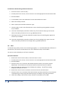
To change the wiper, loosen the set screw in the wiper arm until the wiper assembly can be removed
from the wiping shaft. Place a new wiper assembly on the shaft with the set screw aligned squarely
with the flat on the wiping shaft. Gently press the wiper arm down until the wiper arm hits the stop
on the shaft. The wiper pad should now be compressed to roughly one half its original thickness.
Tighten the set screw - do not over tighten.
NOTE:
It is imperative that the set screw be fastened squarely aligned onto the flat on the shaft
otherwise proper operation will be affected.
CAUTION:
Do not over tighten the set screw or manually attempt to rotate the wiper arm once set onto
the shaft. Any attempt to manually rotate the wiper may cause gearbox damage and void the
warranty.
8.6
Optical Dissolved Oxygen
On a MP47 or MP65 sensor, the ODO parameter will be an end sensor only.
The sensor and electrode may be cleaned using a soft cloth, mild detergents and warm water. If the
sensor shows signs of marine growth a light biocide can be used to clean and kill any biological
growth on the sensor. It is important to take care when cleaning around the sensor optics – do not
scratch the sensor lens.
32
PENTAIR ENVIRONMENTAL SYSTEMS
MP SERIES SENSOR USER MANUAL
The sensor will be damaged by the ingress of water or other solutions into the electronics cavity and
Warranty will be voided if disassembled. Rinse the electrode in clean water prior to installing sensor
or checking calibration.
9
User Calibration and Testing
The factory supplied Certificate of Conformance will provide detailed information regarding the
sensor ranges and specifications; this document should be retained for future reference.
9.1
Pressure Sensors
To maintain high quality control over monitoring programs, it is recommended that pressure
calibration is checked every 3-6 months. If re-calibration is required a method is presented here
using standard methods. Alternatively sensors may be returned to an authorised Greenspan agent
for re-calibration.
The sensor can be checked by use of known pressure inputs, usually from an accurate digital
pressure calibrator or dead weight tester. However a quick check can be done at any time by reading
the sensor in air.
Quick Check method for a gauge pressure sensor:
1. Remove the sensor from the water, ensure the sensor is clean and dry and the vent tube at
the top of the cable is not sealed.
2. Connect the sensor to a PC and run SensorMate.
3. Once connected the monitor screen will display the readings. The Pressure value should
read Zero +/- 0.1% of the full scale range of the sensor.
4. This confirms that the sensor electronics has remained stable and no further action should
be required if the sensor is within +/- 0.1 % FS.
Quick Check method for an absolute pressure sensor:
1. Remove the sensor from the water, ensure the sensor is clean and dry.
2. Connect the sensor to a PC and run SensorMate.
3. Obtain the barometric pressure for the location * where the check is being performed.
4. Once connected the monitor screen will display the readings. The Pressure value should
read the barometric pressure +/- 0.1% of the full scale range of the sensor. (1hPa = 0.010216
m H2O @ 20oC)
5. This confirms that the sensor electronics has remained stable and no further action should
be required if the sensor is within +/- 0.1 % FS.
* The accuracy and calibration of the barometer should be considered when making the comparison.
33
PENTAIR ENVIRONMENTAL SYSTEMS
MP SERIES SENSOR USER MANUAL
Re-Calibration Method Using Digital Pressure Calibrator or Dead Weight Tester:
1. Ensure the sensor is clean and dry.
2. Connect the sensor to the calibrator using an appropriate BSP fitting.
3. Provide power to the sensor, connect sensor to a PC with appropriate communication cable.
4. Run SensorMate
5. In SensorMate, select User Calibration from the SensorMate main menu.
6. Select the Pressure Channel.
7. Select 2 point Span and Offset Calibration Type.
8. Apply the low pressure input to the sensor from the calibrator. Typically this will be zero for
a gauge sensor.
9. The screen should display a window to allow entry of the new low value, type in the new
value to be read by the Sensor for zero, e.g.: (0000.00), click OK.
10. Apply the high pressure input to the sensor from the calibrator. Typically this will be full
scale for a gauge sensor.
11. The screen should display a window to allow entry of the new high value, type in the new
value to be read by the Sensor for the high value, e.g.: (0005.00), If the calibrator cannot set
an output in m of water a conversion will need to be calculated and entered, click OK.
12. Refer to the SensorMate User Manual for further reference.
NOTE: Absolute pressures must be set and entered when calibrating an absolute sensor.
9.2
Electrical Conductivity
To maintain high quality control over monitoring programs, it is recommended EC calibration is
checked at least every 3-6 months. If re-calibration is required a method is presented here using
Greenspan EC Calibrators and using Standard Solutions. Alternatively sensors may be returned to an
authorised Greenspan agent for re-calibration.
Quick Check Method:
The following procedures detail a quick method to check the calibration for both full-scale and zero
using the supplied loop calibrator.
NOTE:
For new EC sensors each calibrator is clearly marked with a serial number and nonnormalised calibration value.
1. Remove the sensor from the water, unscrew the shroud and dry the EC head and
temperature button.
2. Connect the sensor to a PC and run SensorMate.
3. Once connected the monitor screen will display the readings. The EC value should read Zero
+/- 1% of the full scale range of the sensor.
4. Place the loop calibrator through the hole in the EC head and plug the connector together.
34
PENTAIR ENVIRONMENTAL SYSTEMS
MP SERIES SENSOR USER MANUAL
5. The non-normalised EC value should read the value marked on the loop calibrator +/- 1% of
the full scale range of the sensor.
6. This confirms that the sensor electronics has remained stable and no further action should
be required if the sensor is within +/- 1 % FS.
Re-Calibration Method using the EC loop calibrator:
While the EC sensor is designed for long term stability it is normal for any electronics to experience
some drift over time. If re-calibration is required 1. Remove the shroud and ensure the sensor is clean and dry.
2. Provide power to the sensor, connect sensor to a PC with appropriate communication cable.
3. Run SensorMate.
4. In SensorMate, select User Calibration from the SensorMate main menu.
5. Select the EC Channel.
6. Select 2 point Span and Offset Calibration Type.
7. The zero value is read in SensorMate without the loop calibrator. The screen should display
a window to allow entry of the new low value, type in the new value to be read by the
sensor for zero, eg: (0000.00) click OK.
8. Loop the EC calibrator wire through the EC head and connect together.
9. Enter the value marked on the loop calibrator, click OK.
Re-Calibration Method Using EC Calibration Solutions:
The sensor can be checked by use of known laboratory conductivity standards, a thermometer
and/or a third party EC sensor.
1. Ensure the sensor is clean and dry (the shroud should be fitted).
2. Provide power to the sensor, connect sensor to a PC with appropriate communication cable.
3. Run SensorMate.
4. In SensorMate, select User Calibration from the SensorMate main menu.
5. Select the EC Channel.
6. Select 2 point Span and Offset Calibration Type.
7. The zero value is read in air. The screen should display a window to allow entry of the new
low value, type in the new value to be read by the Sensor for zero, eg: (0000.00) click OK.
8. Submerge the sensor in full scale calibration standard. The sensor should be gently agitated
to remove any air bubbles. Allow the temperature of the solution and sensor to stabilize
(recommend at least 1 hour).
9. Enter the non-normalised EC value of the standard solution, click OK.
10. Refer to the SensorMate User Manual for further reference.
35
PENTAIR ENVIRONMENTAL SYSTEMS
MP SERIES SENSOR USER MANUAL
9.3
pH
To maintain high quality control over monitoring programs, it is recommended pH calibration is
checked every 3-6 months.
The sensor can be checked by use of known pH standards (buffer solutions). Alternatively sensors
may be returned to an authorised Greenspan agent for re-calibration.
Quick Check Method: pH Sensors
1. Remove the sensor from the water, ensure the sensor is clean and dry. Dirty electrodes
could be a key source of calibration errors.
2. Provide power to the sensor, connect sensor to a PC with appropriate communication cable.
3. Run SensorMate.
4. Place the sensor in a low level pH buffer (eg. pH 4) so that the electrode is fully submerged.
5. Once connected the monitor screen will display the readings. The pH value displayed on the
monitor screen should be the pH buffer value +/- 1% of the full scale range of the sensor.
6. Carefully rinse the electrode in water and shake off any attached droplets.
7. Place the sensor in a high level pH buffer (e.g. pH 10) so that the electrode is fully
submerged. Record the measured output value.
8. The pH value displayed on the monitor screen should be the pH buffer value +/- 1% of the
full scale range of the sensor.
9. This confirms that the sensor electronics has remained stable and no further action should
be required if the sensor is within +/- 1 % FS.
Re-Calibration Method using pH Buffer Solutions:
1. Ensure the sensor is clean and dry.
2. Provide power to the sensor, connect sensor to a PC with appropriate communication cable.
3. Run SensorMate.
4. In SensorMate, select User Calibration from the SensorMate main menu.
5. Select the pH Channel.
6. Select 2 point Span and Offset Calibration Type.
7. Put the sensor in a solution with a known, low pH (ie. pH buffer). Allow time for the
electrode to stabilize.
8. The screen should display a window to allow entry of the new low value, type in the value of
the low pH buffer, eg: (0004.00), click OK.
36
PENTAIR ENVIRONMENTAL SYSTEMS
MP SERIES SENSOR USER MANUAL
9. Put the sensor in a solution with a known, high pH (ie. pH buffer). Allow time for the
electrode to stabilize.
10. The screen should display a window to allow entry of the new high value, type in the value
of the high pH buffer, eg: (0010.00), click OK
11. Refer to the SensorMate User Manual for further reference.
9.4
ORP
It is not possible to calibrate Eh electrodes over a range of redox potentials (as is done with pH
electrodes). Instead standard solutions that are stable with known redox potentials for specific
indicator electrodes are used to check response.
There are two main solutions used for measuring redox potentials, Light’s solution and Zo Bell’s
solution.
The table below shows the theoretical potential of platinum ORP electrodes using two different
common reference electrodes in the ORP standard Light's solution and Zo Bell’s solution. The actual
potential of the Greenspan ORP electrode in Light's solution is specified as 465mV+/- 10mV.
Comparison Table
Reference
Standard Hydrogen Electrode (SHE)
Greenspan Ag/AgCl Electrode
Light’s Solution
+675mV
+465mV, +/10mV
ZoBell’s Solution
-
+229mV Saturated KCL
If the readings obtained are outside the expected values the electrode should be cleaned and/or
replaced. Sensors may be returned to an authorised Greenspan agent for re-calibration.
Quick Check Method:
1. Remove the sensor from the water; ensure the sensor is clean. Dirty electrodes could be a
key source of calibration errors.
2. Provide power to the sensor, connect sensor to a PC with appropriate communication cable.
3. Run SensorMate.
4. Place the sensor in a standard solution so that the electrode is fully submerged.
5. Once connected the monitor screen will display the readings. The ORP value displayed on
the monitor screen should be the standard solution value +/- 2% of the full scale range of
the sensor.
37
PENTAIR ENVIRONMENTAL SYSTEMS
MP SERIES SENSOR USER MANUAL
Re-Calibration Method Using Calibration Solutions:
1. Ensure the sensor is clean and dry.
2. Provide power to the sensor, connect sensor to a PC with appropriate communication cable.
3. Run SensorMate.
4. In SensorMate, select User Calibration from the SensorMate main menu.
5. Select the ORP Channel.
6. Select 1 point Offset Calibration Type.
7. Put the sensor in a solution with a known ORP value. Allow time for the electrode to
stabilize.
8.
The screen should display a window to allow entry of the new low value, type in the value of
the standard solution, e.g.: (0228.00), Click OK.
9. Refer to the SensorMate User Manual for further reference.
9.5
Turbidity
The sensor can be checked by use of known laboratory Turbidity standards. Sensors are calibrated
using AMCO CLEAR® TURBIDITY STANDARD, for ANALITE ISO 7027 PROBES.
The claimed advantages of these standards are•
•
•
•
•
•
•
Safe, non-toxic and disposable
Easy-to-use/No dilutions or preparations
Accurate to 1% lot-to-lot
Available in a wide range of values
Stable/does not settle out of suspension
Guaranteed One Year Shelf Life
N.I.S.T. Traceable
Quick Check Method:
1. Remove the sensor from the water, ensure the sensor is clean and dry.
2. Place the sensor in clean water so that the sensor face is at least 50mm clear of the bottom
of the container.
3. Provide power to the sensor, connect sensor to a PC with appropriate communication cable.
4. Run SensorMate.
5. Once connected the monitor screen will display the readings. The Turbidity value should
read Zero +/- 3% of the full scale range of the sensor.
6. Place the sensor in a full scale Turbidity solution so that the sensor face is at least 50mm
clear of the bottom of the container.
7. The Turbidity value should read +/- 3% of the full scale range of the sensor.
8. This confirms that the sensor electronics has remained stable and no further action should
be required if the sensor is within +/- 3 % FS.
38
PENTAIR ENVIRONMENTAL SYSTEMS
MP SERIES SENSOR USER MANUAL
Re-Calibration Method Using Calibration Solutions:
1. Ensure the sensor is clean and dry.
2. Provide power to the sensor, connect sensor to a PC with appropriate communication cable.
3. Run SensorMate.
4. In SensorMate, select User Calibration from the SensorMate main menu.
5. Select the Turbidity Channel.
6. Select 2 point Span and Offset Calibration Type.
7. The zero value is read in clean filtered water. Sensor should be gently agitated to remove
any air bubbles.
8. The screen should display a window to allow entry of the new low value, type in the new
value to be read by the Sensor for zero, eg: (0000.00) click OK.
9. Submerge the sensor in full scale calibration standard. Sensor should be gently agitated to
remove any air bubbles.
10. The screen should display a window to allow entry of the new high value, type in the new
value to be read by the Sensor for the high value, eg: (0400.00) click OK.
9.6
ODO
To maintain high quality control over monitoring programs, it is recommended ODO calibration is
checked every 3-6 months. The MP Sensor has a user calibration facility in SensorMate.
The sensor can be checked by use of known standards.
Quick Check Method:
1. Remove the sensor from the water, ensure the sensor is clean.
2. Provide power to the sensor, connect sensor to a PC with appropriate communication cable.
3. Run SensorMate.
4. Place the sensor into a container with Sodium Sulphite solution (2 tea spoons Sodium
Sulphite per 1 litre of water) for at least 10 minutes to allow the sensor to stabilise.
5. Once connected, the monitor screen will display the readings. The DO% Sat reading
displayed, should be ±1% of 0% .
6. Remove the sensor from the container and rinse the sensor with clean water.
7. Place the sensor into a container of full scale solution (tap water aerated by an air pump and
circulated using a water pump) and allow the sensor to stabilise for at least 10 minutes..
8. Check the reading on the monitor screen, the DO % sat should be ±1% of 98%.
39
PENTAIR ENVIRONMENTAL SYSTEMS
MP SERIES SENSOR USER MANUAL
9. This confirms that the sensor electronics has remained stable and no further action should
be required if the sensor is within +/- 1% of these readings in different conditions.
Re-Calibration Method Using Calibration Solutions
1. Ensure the sensor is clean and dry.
2. There are 2 steps to complete the calibration for an MP sensor with Optical DO:
- the 1 Point Offset ( zero calibration) and,
- the 1 Point Span (full scale calibration)
3. Connect the sensor with the appropriate communication cable and turn on the DC power.
4. Run SensorMate.
5. In SensorMate, select User Calibration from the SensorMate main menu.
6. Select the calibration channel – ODO
7. Perform the zero calibration by selecting 1 Point offset in the Calibration Type.
8. Place the sensor into a Sodium Sulphite solution and allow 10 minutes to stabilise. Ensure
the ODO head is fully submerged.
9. Click on the Calibrate Channel button.
10. The screen should display a window to allow entry of the new low value, type in 0 and click
OK once the value has been entered.
11. Remove the sensor from the container and rinse it with clean water.
12. Perform full scale calibration by selecting 1 Point Span
13. Place the sensor into an aerated full scale and allow to stabilise for at least 10 minutes.
Ensure the ODO head is fully submerged.
14. Click on the Calibrate Channel button.
15. The screen should display a window to allow entry of the new high value. Enter the new
value e.g. 98% for the full scale value and click OK
16. Click on Monitor to verify the readings on the screen.
40
PENTAIR ENVIRONMENTAL SYSTEMS
MP SERIES SENSOR USER MANUAL
10 Modbus notes
10.1 Holding Registers
Sensor information can be mapped to Modbus holding registers. This provides an easy transfer of
data to the many devices that support Modbus. The user can select Modbus RTU (default) or
Modbus ASCII.
SensorMate V2.1 software has a feature to assist with setting up Modbus holding registers. When
“Modbus Registers” is clicked in the Sensor Setup tree, a list of available channels will be displayed
with a selection box. Selecting a Sensor channel will allocate 6 holding registers for channel
information. A table will update and display the holding registers allocated. The Ok button must be
pressed to send this setup to the sensor.
Each channel mapped to Modbus take 6 registers starting from 100 (see table below).
41
Address
decimal
R
Type
001xx + 0
UC8
Channel number
001xx + 1
UC8
Units code
001xx + 2
Float
Last Scanned Value
001xx + 4
Float
Last Logged Value
PENTAIR ENVIRONMENTAL SYSTEMS
Description
MP SERIES SENSOR USER MANUAL
The sensor’s configuration file contains the information of which channels are mapped to these
Modbus registers.
10.2 Show registers button
There is also a “Show registers” button that provides other information that is also written to
holding registers.
10.3 Codes and Terminology
The following list of codes, abbreviations and terms may be used in the software coding of these
structures:
Bool
UC8
UI16
SI16
UI32
SI32
F32
42
8 bit character used to represent TRUE and FALSE
Unsigned 8 bit character
unsigned 16 bit integer
signed 16 bit integer
unsigned 32 bit integer
signed 32 bit integer
IEEE754 single precision floating point 32 bit value.
PENTAIR ENVIRONMENTAL SYSTEMS
MP SERIES SENSOR USER MANUAL
Cal
Config
CV
HO
LO
Calibration
Configuration
Current Values
High order – upper 8 bits of a 16 bit word
Low order – lower 8 bits of a 16 bit word.
10.4 Integer and Floating Point Values
The Modbus protocol specifies that the order of bytes is sent as low order first. For example, when
sending a value of 0x1234, the first byte sent is 0x12 followed by the value 0x34.
10.5 32 Bit Values
The Modbus registers for 32 bit integer and floating point values are aligned on even register
numbers and must be read and written in a single function call. For example, to read a 32 bit value
from registers 00102/00103, call function code 03, start register 00102 and read two register values.
An attempt to read register 00103 will result in an exception response.
10.6 Floating Point
All floating-point variables (denoted as type F32) are IEEE754 Floating Point format (single precision
32 bit). Example:
Read registers 00100 and 00101: flow velocity which has a value of 51.392.
The Modbus registers return 0x424d and 0x9225 from addresses 0100 and 0101.
This data corresponds to 0x25924d42 (low byte first) which is the same as
51.3297. See test code below:
/* PC
c[0]
c[1]
c[2]
c[3]
code example */
= 0x25;
/* last byte from register read */
= 0x92;
= 0x4d;
= 0x42;
/* first byte from register read */
t = *((float*) &c[0]);
printf("%f", t);
/* value printed is 51.392 */
10.7 Updating Register Data
As per the Modbus protocol, data contained in registers is immediately sent on request. This may
mean that the data sent may not be recent. To allow the user to obtain the most current data
possible, using only Modbus commands, a request for data also starts the "Get Current Values"
routine in the sensor, where all parameters that are set up in the monitor screen are read.
Get Current Values for a typical MP sensor would be complete within 6 seconds (5 second warm-up
time + <1 second process time). When complete the "Last Scanned Values" are updated. To get the
most current data a user can read the registers, wait until the sensor has a chance to get current
values, and read registers again.
43
PENTAIR ENVIRONMENTAL SYSTEMS
MP SERIES SENSOR USER MANUAL
Alternatively, if the sensor’s logging schedule is on, the data in the “Last Scanned Value” registers
will be updated according to this schedule (e.g. if a 3 minute scan time is set, the data in the Last
Scanned Value registers will be no older the 3 minutes when read).
10.8 Command Set – Modbus Function Codes
Func
Code
Modbus Function
Description
03
Read multiple registers
16
Write registers - multiple
65-69
User commands
Uses for 3000 Series
Read current values, calibration data, basic calibration data
and confguration data.
Write current values, calibration data, basic calibration
data and confguration data.
Initiate a scan.
See following section
10.9 Command Set – User Function Codes
Function
Code
65
66
67
68
69
User Function
Description
Set Date and Time
Start Logging
Stop Logging
Wipe now
Read Channel Name
Uses for 3000 Series
Future use
Future use
Clears totals, as per flags sent as command parameters.
Enter passcode to gain level 0, 1 or 2 access and to log out.
Returns a text string for a given channel number
10.10 Exception Responses
44
Exception
Code
Description
01
02
03
05
06
Illegal Function
Illegal Data Address
Illegal Data Value
ACK Acknowledge
Busy, message rejected
07
NAK
PENTAIR ENVIRONMENTAL SYSTEMS
Uses for 3000 Series
The received function code is not a valid
The address in the data field is not valid
The value in the data field is outside limits
The function is valid and is being processed
The message was received without error but the 3000
Series cannot perform the operation. Retry later.
Access denied – operation cannot be performed
MP SERIES SENSOR USER MANUAL
TURBIDITY
EC
ORP
PH
PRESSURE
11 Specification
45
Measurement technique
½˝ Ceramic Capacitance Sensor
Standard Pressure ranges available
Gauge 2.5, 5, 10, 20, 40, 75, 100 m Absolute 20, 40, 75, 100 m
Max Over Range
4 times Full Scale range.
Other Ranges available
Yes – Calibration charge may apply – refer sales office
Overall Accuracy (combined
linearity, hysteresis and
repeatability)
± 0.1% Full Scale range
Long term stability
0.2% full scale per annum
Resolution
Depth – 0.001 m , Temp – 0.05°C,
Measurement Technique
Gel-filled glass electrode with internal Ag/AgCl reference; Field replaceable electrode
Sensor Range
0–14 pH
Resolution
0.001 pH
Accuracy
± 0.2 pH
Measurement Technique
Platinum electrode with internal Ag/AgCl reference; Field replaceable electrode
Sensor Range
–1000 mV – ±1000 mV
Resolution
1 mV
Accuracy
± 2% full scale
Measurement Technique
Toroidal Conductivity
Standard EC ranges available
0–1000 µS/cm, 0–2000 µS/cm, 0–5000 µS/cm, 0–10000 µS/cm, 0–20000 µS/cm, 0–
60000 µS/cm, 0–70000 µS/cm.
Other Ranges are available
Yes – calibration charge may apply – refer sales office
Overall Accuracy (combined
linearity, hysteresis and
repeatability)
±1 % full scale range
Resolution
EC – 1 µS
Measurement Technique
90° Infra-red (ISO7027)
Standard ranges available (factory
set)
100 NTU,
400 NTU
1000 NTU
Resolution
0.1 NTU
0.2 NTU
0.3 NTU
Linearity
± 1%
± 1%
± 3%
Temperature Coefficient
± 0.2% /°C
± 0.1% /°C
± 0.1% /°C
Calibration Standard
APS AEPA polymer solutions 0, 100 NTU, 400 NTU, 1000 NTU
PENTAIR ENVIRONMENTAL SYSTEMS
MP SERIES SENSOR USER MANUAL
OPTICAL DO
TEMP
46
Measurement Technique
Oxygen fluorescence detection method
Sensor Range
0–200% saturation (0-20 ppm)
Resolution
0.1%,
Accuracy
Oxygen 1% of reading or 0.02 ppm whichever is greater
Response Time
90% of DO change within 60 seconds
Measurement Technique
Integrated precision thermistor
Operating ranges
0–50°C
Overall Accuracy (combined
linearity, hysteresis and
repeatability)
0.2 Deg
Sensor Outputs
Internal Data Logger – serial data via SensorMate software Optional adaptor provides
SDI12 serial output (3 wire)
Storage Temperature
–5 Deg C – +60 Deg C
Cable type
Polyurethane sheathed cable, OD 8 mm, with 3 mm vent tube, moulded entry, HS7
connector for serial connection.
Standard Cable lengths
10, 20, 30, 50, 100, 150 m (32, 65, 100, 165, 325, 490 ft)
Non-standard Cable Lengths
Yes – (Extra cable moulding time may be required)
Power supply
8 to 30 V DC (at sensor), or on-board battery pack (option)
Power ESD protection
2000 volts
Current consumption
Sleep ± 0.2 mA, logging 20 mA, communicating 30 mA (consumption rates vary
depending on parameters selected)
Sensor warm up time
Up to 5 seconds
On-board battery pack (option)
Housing screws to sensor size (OD × L) 47 mm × 250 mm
Battery capacity
9 × Lithium AA (3.6Volt) – Total capacity 5.2 Ah @ 10.8 v
Typical field life (battery pack)
Over 12 month’s remote operation @ 15 minute data logging.
Internal data logger
Non-volatile, battery backed RAM with real time clock
Memory size
4 Mb capacity, with user selectable wrap function
Measuring units
User definable (Metric and Imperial US units)
Data storage
250,000 readings. (Typically 5 minute data for >12 months)
Logging frequency
User selectable from 1 second up to once per day
Dimensions (L × OD)
MP47 – 355 mm × 47 mm (14˝ × 1.78˝), MP65 – 355 mm × 65 mm (14˝ × 2.5˝) –
Optional End Mount Batt Pack – 300 mm × 47 mm
Weight
MP47 – 550 g plus cable weight (665g per 10m length) MP 65 – 650 g (plus cable
weight (665g per 10 m length)
Wetted materials
Acetal, ceramic, 316 passivated stainless steel, polyurethane, viton
PENTAIR ENVIRONMENTAL SYSTEMS
MP SERIES SENSOR USER MANUAL
12 Contact Us
ASIA / PACIFIC:
[email protected]
+ 61 1300 797 246
AUSTRALIA
New South Wales
268-292 Milperra Rd.
Milperra, NSW 2214
Phone: +61 2 9792 0201
Fax: +61 2 9772 2960
Queensland
240 Lavarack Ave
Eagle Farm, QLD 4009
Phone: +61 7 3866 7850
Fax: +61 7 3260 1916
Western Australia
70 Cleaver Tce
Belmont, WA 6104
Phone: +61 8 9477 1188
Fax: +61 8 9479 6727
ASIA
390 Havelock Road,
#04-01,
King’s Centre,
Singapore. 169662
Phone: +65 6869 8916
USA / REST OF WORLD:
[email protected]
+ 1 407 886 3939
NORTH AMERICA
2395 Apopka Blvd.
Apopka, FL 32703
United States
Office: 1.407.992.5592
Fax: 1.866.260.0753
47
PENTAIR ENVIRONMENTAL SYSTEMS
MP SERIES SENSOR USER MANUAL