1
INSTRUCTION MANUAL
HF/50 MHz TRANSCEIVER
i7410
FOREWORD
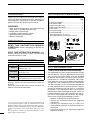
SUPPLIED ACCESSORIES
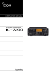
Thank you for making the IC-7410 your radio of
choice. We hope you agree with Icom’s philosophy of
“technology first.” Many hours of research and development went into the design of your IC-7410.
FEATURES
❍ High receiver performance: third-order intercept
point (IP3) of +30 dBm (HF bands only)
❍ Simple band scope function
❍ ±0.5 ppm of high frequency stability
❍ RTTY demodulator and decoder
❍ RS-BA1 compatible
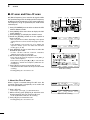
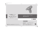
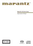
The transceiver comes with the following accessories.
Qty.
qHand microphone ............................................ 1
wDC power cable*1 . ........................................... 1
eSpare fuse (ATC 5 A) ....................................... 1
rSpare fuse (ATC 30 A) ..................................... 2
tACC cable.......................................................... 1
y6.3 (d) mm plug.................................................. 1
uFerrite EMI filter*2. ............................................. 1
*1 D
iffers depending on the version.
*2 Not supplied with the non-European versions.
q
IMPORTANT
r
t
READ THIS INSTRUCTION MANUAL
CAREFULLY before attempting to operate the
y
transceiver.
For European versions
SAVE THIS INSTRUCTION MANUAL. This
manual contains important safety and operating
instructions for the IC-7410.
EXPLICIT DEFINITIONS
w
w
u
(see p. 19 for installation details)
WORD
DEFINITION
RDANGER!
Personal death, serious injury or an
explosion may occur.
FCC INFORMATION
RWARNING!
Personal injury, fire hazard or electric
shock may occur.
• FOR CLASS B UNINTENTIONAL RADIATORS:
This equipment has been tested and found to comply
with the limits for a Class B digital device, pursuant to
part 15 of the FCC Rules. These limits are designed
to provide reasonable protection against harmful
interference in a residential installation. This equipment generates, uses and can radiate radio frequency
energy and, if not installed and used in accordance
with the instructions, may cause harmful interference
to radio communications. However, there is no guarantee that interference will not occur in a particular
installation. If this equipment does cause harmful
interference to radio or television reception, which can
be determined by turning the equipment off and on,
the user is encouraged to try to correct the interference by one or more of the following measures:
• Reorient or relocate the receiving antenna.
• Increase the separation between the equipment
and receiver.
• C onnect the equipment into an outlet on a
circuit different from that to which the receiver is
connected.
• Consult the dealer or an experienced radio/TV
technician for help.
CAUTION
NOTE
Equipment damage may occur.
If disregarded, inconvenience only. No risk
of personal injury, fire or electric shock.
Spurious signals may be received near some frequencies.
These are made in the internal circuit and does not
indicate a transceiver malfunction.
Icom, Icom Inc. and the Icom logo are registered trademarks of
Icom Incorporated (Japan) in Japan, the United States, the United
Kingdom, Germany, France, Spain, Russia and/or other countries.
Microsoft, Windows and Windows Vista are registered trademarks
of Microsoft Corporation in the United States and/or other countries.
All other products or brands are registered trademarks or trademarks of their respective holders.
i
e
PRECAUTIONS
R DANGER HIGH RF VOLTAGE! NEVER
attach an antenna or internal antenna connector
during transmission. This may result in an electrical
shock or burn.
R WARNING! NEVER operate the transceiver
with a headset or other audio accessories at high
volume levels. Hearing experts advise against continuous high volume operation. If you experience a ringing
in your ears, reduce the volume or discontinue use.
CAUTION: NEVER install the transceiver in a
place without adequate ventilation. Heat dissipation
may be reduced, and the transceiver may be damaged.
DO NOT use harsh solvents such as benzine or
alcohol when cleaning, as they will damage the transceiver surfaces.
DO NOT push the PTT switch when you don’t actually desire to transmit.
R WARNING! NEVER operate or touch the
DO NOT use or place the transceiver in areas with
transceiver with wet hands. This may result in an
electric shock or damage to the transceiver.
temperatures below ±0°C (+32°F) or above +50°C
(+122°F).
R WARNING! NEVER apply AC power to the
[DC13.8V] socket on the transceiver rear panel. This
could cause a fire or damage the transceiver.
DO NOT place the transceiver in excessively dusty
1
2
3
environments or in direct sunlight.
DO NOT place the transceiver against walls or
putting anything on top of the transceiver. This may
overheat the transceiver.
4
Always place unit in a secure place to avoid inadvertent use by children.
6
R WARNING! NEVER apply more than 16 V
DC to the [DC13.8V] socket on the transceiver rear
panel, or use reverse polarity. This could cause a fire
or damage the transceiver.
BE CAREFUL! If you use a linear amplifier, set
7
R WARNING! NEVER let metal, wire or other
objects protrude into the transceiver or into connectors
on the rear panel. This may result in an electric shock.
BE CAREFUL! The rear panel will become hot
when operating the transceiver continuously for long
periods of time.
R WARNING! NEVER cut the DC power cable
between the DC plug and fuse holder. If an incorrect
connection is made after cutting, the transceiver may
be damaged.
R WARNING! Immediately turn OFF the trans-
the transceiver’s RF output power to less than the
linear amplifier’s maximum input level, otherwise, the
linear amplifier will be damaged.
ceiver power and remove the power cable if it emits
an abnormal odor, sound or smoke. Contact your
Icom dealer or distributor for advice.
USE only the specified microphone. Other manufacturers’ microphones have different pin assignments,
and connection to the IC-7410 may damage the
transceiver or microphone.
R WARNING! NEVER put the transceiver in
any unstable place (such as on a slanted surface or
vibrated place). This may cause injury and/or damage
to the transceiver.
During maritime mobile operation, keep the transceiver and microphone as far away as possible from
the magnetic navigation compass to prevent erroneous indications.
CAUTION: NEVER change the internal settings of
the transceiver. This may reduce transceiver performance and/or damage to the transceiver.
In particular, incorrect settings for transmitter circuits,
such as output power, idling current, etc., might
damage the expensive final devices.
The transceiver warranty does not cover any problems caused by unauthorized internal adjustment.
5
8
9
10
11
12
13
14
15
Turn OFF the transceiver’s power and/or disconnect
the DC power cable when you will not use the transceiver for long period of time.
16
17
For U.S.A. only
CAUTION: Changes or modifications to this device,
not expressly approved by Icom Inc., could void your
authority to operate this device under FCC regulations.
18
19
CAUTION: NEVER block any cooling vents on
the top, rear, sides or bottom of the transceiver.
20
CAUTION: NEVER expose the transceiver to
21
rain, snow or any liquids.
ii
TABLE OF CONTENTS
FOREWORD............................................................... i
IMPORTANT................................................................ i
EXPLICIT DEFINITIONS............................................. i
SUPPLIED ACCESSORIES....................................... i
FCC INFORMATION................................................... i
PRECAUTIONS.......................................................... ii
TABLE OF CONTENTS............................................ iii
1 PANEL DESCRIPTION................................... 1–14
■ Front panel......................................................... 1
■ Rear panel.......................................................... 8
D ACC socket information............................... 10
■ LCD display...................................................... 11
■ Function display............................................... 13
D M1 (Menu 1)................................................ 13
D Function keys on M1 (Menu 1).................... 13
D M2 (Menu 2)................................................ 14
D Function keys on M2 (Menu 2).................... 14
2 INSTALLATION AND CONNECTIONS......... 15–22
■ Selecting a location.......................................... 15
■ Grounding........................................................ 15
■ Antenna connection......................................... 15
■ Required connections...................................... 16
D Front panel................................................... 16
D Rear panel................................................... 16
■ Advanced connections..................................... 17
D Front panel................................................... 17
D Rear panel................................................... 17
■ External keypad connections........................... 18
■ External antenna tuner connection.................. 18
D Connecting the AH-4................................... 18
■ Power supply connections................................ 19
■ Connecting to a DC power supply.................... 19
D Connecting to the PS-126 DC POWER
SUPPLY....................................................... 19
D Connecting to a non-Icom DC POWER
SUPPLY....................................................... 19
■ Linear amplifier connections............................ 20
D Connecting the IC-PW1/PW1EURO............ 20
D Connecting a non-Icom linear amplifier....... 21
■ Microphone connector information................... 22
■ Microphones..................................................... 22
D HM-36.......................................................... 22
D SM-50 (option)............................................. 22
iii
3 BASIC OPERATION...................................... 23–34
■ Before first applying power............................... 23
■ Turning ON (CPU resetting)............................. 23
■ VFO description................................................ 24
D Selecting the VFO A/B................................. 24
D VFO equalization......................................... 24
■ Selecting VFO/Memory mode.......................... 24
■ Selecting a frequency band.............................. 25
D Using the band stacking registers................ 25
■ Frequency setting............................................. 26
D Tuning with [DIAL]....................................... 26
D Direct frequency entry with the keypad........ 26
D Quick Tuning function................................... 27
D Selecting 1 Hz step...................................... 27
D 1⁄4 Tuning Step function............................... 27
D Auto Tuning Step function........................... 28
D About the 5 MHz frequency band operation
(USA version only)....................................... 28
D Band edge warning beep............................. 29
D Programming the user band edge............... 30
■ Operating mode selection................................ 31
■ Volume setting.................................................. 31
■ Squelch and receive (RF) sensitivity................ 32
■ Voice synthesizer operation............................. 33
■ Meter Display selection.................................... 33
■ Basic transmit operation................................... 34
D Transmitting.................................................. 34
D Microphone gain adjustment........................ 34
4 RECEIVE AND TRANSMIT........................... 35–52
■ Operating SSB................................................. 35
■ Operating CW.................................................. 36
D About the CW reverse mode........................ 37
D About CW pitch control................................ 37
D About keying speed..................................... 37
D CW sidetone function................................... 37
■ Electronic keyer functions................................ 38
D Memory keyer menu construction................ 38
D Memory keyer send menu........................... 39
D Editing a memory keyer............................... 40
D Contest number Set mode........................... 41
D Keyer Set mode........................................... 42
■ Operating RTTY (FSK)..................................... 44
■ RTTY functions................................................ 45
D RTTY menu construction............................. 45
D About the RTTY reverse mode.................... 46
D RTTY decoder.............................................. 46
D Twin Peak Filter............................................ 47
D RTTY Set mode........................................... 48
■ Operating AM/FM............................................. 49
Tone squelch operation.................................... 50
■ Tone scan operation......................................... 51
Repeater operation.......................................... 51
D Repeater access tone frequency setting...... 52
D Transmit frequency monitor check............... 52
5 FUNCTIONS FOR RECEIVE......................... 53–61
■ RIT function...................................................... 53
D RIT Monitor function..................................... 53
■ Simple band scope........................................... 54
■ Preamplifier...................................................... 55
■ Attenuator......................................................... 55
■ AGC function.................................................... 56
D AGC speed selection................................... 56
D Setting the AGC time constant..................... 56
■ IF filter selection............................................... 57
D IF filter selection........................................... 57
D Filter passband width setting....................... 57
D 1st IF filter selection..................................... 58
D IF (DSP) filter shape.................................... 58
■ Twin PBT operation.......................................... 59
■ Noise Blanker................................................... 60
D NB Set mode................................................ 60
■ Meter Peak Hold function................................. 60
■ Noise Reduction............................................... 61
■ Dial Lock function............................................. 61
■ Notch function.................................................. 61
6 FUNCTIONS FOR TRANSMIT...................... 62–68
■ VOX function..................................................... 62
D Using the VOX function................................ 62
D Adjusting the VOX function.......................... 62
■ Break-in function.............................................. 63
D Semi Break-in operation.............................. 63
D Full Break-in operation................................. 63
■ Speech Compressor........................................ 64
■ Transmit filter width selection............................. 64
■ ∂TX function.................................................... 65
D ∂TX Monitor function................................... 65
■ Monitor function................................................ 65
■ Split frequency operation................................. 66
■ Quick Split function.......................................... 67
D Split Lock function........................................ 67
■ Measuring SWR............................................... 68
D Spot measurement....................................... 68
D Plot measurement........................................ 68
1
2
3
4
5
6
7
8
9
10
11
12
13
14
15
16
17
18
19
20
21
iv
TABLE OF CONTENTS
7 MEMORY OPERATION................................. 69–74
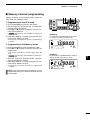
■ General description.......................................... 69
D Memory channel contents............................ 69
■ Memory channel selection............................... 69
D Selection in the VFO mode.......................... 69
D Selection in the Memory mode.................... 69
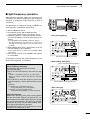
■ Memory channel programming........................ 70
D Programming in the VFO mode................... 70
D Programming in the Memory mode.............. 70
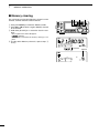
■ Memory clearing.............................................. 71
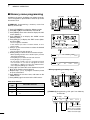
■ Memory contents copying................................ 72
D Copying in the VFO mode............................ 72
D Copying in the Memory mode...................... 72
■ Memory name programming............................ 73
■ Memo Pad function.......................................... 74
D Writing the displayed data into a memo pad... 74
D Calling up a memo pad................................ 74
8
SCANS.......................................................... 75–81
■ Scan types....................................................... 75
■ Preparation....................................................... 76
■ Voice Squelch Control function........................ 76
■ Scan Set mode................................................. 77
■ Programmed scan/Fine programmed scan
(VFO mode)..................................................... 78
D About the Fine programmed scan................ 78
■ Memory scan (Memory mode)......................... 79
D Memory scan............................................... 79
D Select Memory scan.................................... 80
D Setting/Cancelling Select Memory channels.. 80
■ ∂F scan and Fine ∂F scan.............................. 81
D About the Fine ∂F scan............................... 81
v
9 ANTENNA TUNER OPERATION.................. 82–84
■ Antenna connection and selection................... 82
■ Antenna tuner operation................................... 83
D Tuner operation............................................ 83
D Manual tuning.............................................. 83
■ Optional external tuner operation..................... 84
10SET MODE.................................................... 85–91
■ Set mode description....................................... 85
D The Set mode settings................................. 85
■ Tone Control Set mode description.................. 90
D The Tone control Set mode settings............ 90
11DATA COMMUNICATION.............................. 92–93
■ Connections..................................................... 92
D When connecting to [ACC].......................... 92
D When connecting to [MIC]........................... 92
■ Packet (AFSK) operation.................................. 93
D Frequency display during AFSK operation.. 93
12OPTION INSTALLATION.............................. 94–95
■ Opening the transceiver’s case........................ 94
■ FL-430/FL-431 1st if filter installation........... 95
13MAINTENANCE.......................................... 96–100
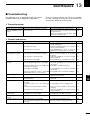
■ Troubleshooting................................................ 96
D Transceiver power........................................ 96
D Transmit and receive.................................... 96
D Scanning...................................................... 97
D Display......................................................... 97
■ Dial tuning tension adjustment......................... 97
■ Frequency calibration (approximate)................ 98
■ About protection displays................................. 98
■ Fuse replacement............................................ 99
D DC power cable fuse replacement............... 99
D Circuitry fuse replacement........................... 99
■ Resetting the CPU......................................... 100
D Partial reset................................................ 100
D All reset...................................................... 100
14CONTROL COMMAND............................. 101–108
■ Remote jack (CI-V) information...................... 101
D CI-V connection example........................... 101
D Data format................................................ 101
D Command table......................................... 102
D Data content description............................ 106
15SPECIFICATIONS..................................... 109–110
■ General.......................................................... 109
■ Transmitter..................................................... 109
■ Receiver......................................................... 110
■ Antenna tuner................................................. 110
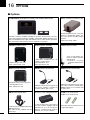
16OPTIONS................................................... 111–112
■ Options........................................................... 111
17CE.............................................................. 113–114
1
2
3
4
5
6
7
8
9
10
11
12
13
14
15
16
17
18
19
20
21
vi
1
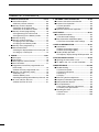
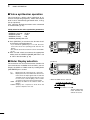
PANEL DESCRIPTION
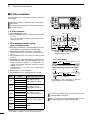
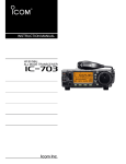
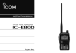
■ Front panel
q
w
e
r
t
y
u
i o !0 !1 !2 !3
!4
!5
!6
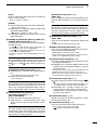
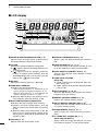
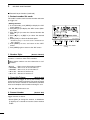
qPOWER SWITCH [POWER] (p. 23)
➥Push to turn ON the transceiver power.
• First, confirm the DC power source is turned ON.
➥Hold down for 1 second to turn OFF the power.
wTRANSMIT SWITCH [TRANSMIT] (p. 34)
Push to select transmit or receive.
• While transmitting, the TX indicator (@1) lights red.
• While receiving or when the squelch opens, the RX indicator (i) lights green.
eANTENNA TUNER SWITCH [TUNER] (pp. 83, 84)
➥Push to turn the internal antenna tuner ON or
OFF (bypass).
yELECTRONIC KEYER JACK [ELEC-KEY]
Plug in a bug or paddle type key to use the internal
electronic keyer for CW operation. (p. 16)
• When the tuner is ON, “
” appears.
• The internal antenna tuner settings can be memorized in each frequency band.
• Select the ELEC-KEY, BUG KEY or Straight key keyer
type in the “Keyer Type” item of the Keyer Set mode.
• When a straight key is connected, “Straight key” must
be selected in the “Keyer Type” item of the Keyer Set
mode. (p. 43)
• A straight key jack is located on the rear panel. See
[KEY] on pages 8 and 16.
• You can reverse the keyer paddle polarity (dot and
dash) in the “Paddle Polarity” item of the Keyer Set
mode. (p. 42)
• Four keyer memory channels are available for your convenience. (p. 40)
(dot)
(com)
(dash)
➥Hold down for 1 second to manually start the antenna tuner.
• If the tuner cannot tune the antenna within 20 seconds, the tuning circuit is automatically bypassed.
rANTENNA•METER SWITCH [ANT•METER]
ANTENNA SWITCH Operation
➥ Push to select either the ANT1 or ANT2 connector. (p. 82)
METER SWITCH Operation
➥ Hold down for 1 second to display either the
COMP or SWR meter in addition to the ALC
meter. (p. 33)
uMICROPHONE CONNECTOR [MIC]
Plug in the supplied or optional microphone.
• See page 22 for appropriate microphones and microphone connector information.
iRX INDICATOR
L ights green while receiving or when the squelch
opens.
oAF CONTROL [AF] (inner control; p. 31)
Rotate to adjust audio output level to the speaker or
headphones.
tHEADPHONE JACK [PHONES] (p. 17)
Plug in standard stereo headphones. Impedance: 8
to 16 ø.
1
• Output power: 5 mW with an 8 ø load.
• When headphones are connected, the internal speaker,
and any external speaker, are disabled.
Increases
Decreases
PANEL DESCRIPTION
!0RF GAIN CONTROL/SQUELCH CONTROL
[RF/SQL] (outer control; p. 32)
Rotate to adjust the RF gain and squelch threshold
level.
The squelch removes noise output to the speaker
when no signal is received (closed condition).
1
!1MIC GAIN CONTROL [MIC] (inner control; p. 34)
Rotate to adjust the microphone gain.
• The transmit audio tone in the SSB, AM and FM modes
can be independently adjusted in the Tone Control Set
mode. (pp. 90, 91)
✔ How to set the microphone gain.
While speaking at normal voice level, adjust the microphone gain so that in the SSB or AM modes, the
ALC meter swings within the ALC zone.
Recommended level for
Icom microphones
• The squelch is particularly effective in FM, but also
works in other modes.
• The 12 to 1 o’clock position is recommended for the
most effective use of the [RF/SQL] control.
• [RF/SQL] operates as only an RF gain control in SSB,
CW and RTTY (Squelch is fixed open), or a squelch
control in AM and FM (RF gain is fixed at maximum
sensitivity), when the “RF/SQL Control” item is set to
“Auto” in the Set mode. (p. 86)
• When used as an RF gain/squelch control
Noise squelch (FM mode)
Recommended level
Squelch is
open.
Decreases
1
Increases
2
!2RF POWER CONTROL [RF PWR]
(outer control; p. 34)
Rotate to continuously vary the RF output power
between 2 W (minimum) and 100 W (maximum).
(AM: between 2 W and 27 W).
3
4
5
6
Maximum
RF gain
RF gain
adjustable
range
S-meter
squelch
• When used as an RF gain control
(Squelch is fixed open; SSB, CW and RTTY only)
Maximum
RF gain
Adjustable
range
Minimum RF gain
While rotating the RF gain control, a faint noise may
be heard. This comes from the DSP unit and does
not indicate an equipment malfunction.
• When used as a squelch control
(RF gain is fixed at maximum.)
Noise squelch (FM mode)
Noise squelch
threshold
(FM mode)
Squelch is
open.
Shallow
S-meter squelch
threshold
S-meter
squelch
Deep
7
8
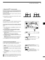
!3ELECTRONIC CW KEYER SPEED CONTROL
[KEY SPEED] (p. 37)
(Mode: CW)
Rotate to adjust the keying speed of the internal
electronic CW keyer to between 6 wpm (minimum)
and 48 wpm (maximum).
Slow
9
10
11
Fast
12
!4BREAK IN DELAY CONTROL [BK-IN DELAY]
(p. 63)
(Mode: CW)
Rotate to adjust the transmit-to-receive switching
delay time for the Semi Break-in function.
Short delay
for high speed
keying
13
14
15
Long delay for
slow speed
keying
16
!5COMPRESSOR CONTROL [COMP] (p. 64)
(Mode: SSB)
Rotate to adjust the compression level.
Decreases
17
18
Increases
19
!6MONITOR GAIN CONTROL [MONI GAIN] (p. 65)
Rotate adjust the monitor level for the clearest
audio output.
Decreases
20
21
Increases
2
1
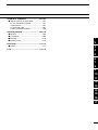
PANEL DESCRIPTION
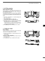
■ Front panel (continued)
@0
@1
!9 !8 !7
@2
@3
@4
@5
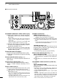
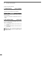
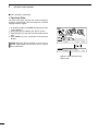
!7NOISE BLANKER SWITCH [NB] (p. 60)
➥Push to turn the Noise Blanker ON or OFF. The
Noise Blanker reduces pulse-type noise such as
that generated by vehicle ignition systems. The
Noise Blanker cannot be used in the FM mode,
and is not effective for non-pulse-type noise.
• “NB” appears when the Noise Blanker is ON.
➥ Hold down for 1 second to display the “NB”
screen. Push to return to the previous screen
display.
!8NOISE BLANKER LEVEL CONTROL [NB]
(outer control; p. 60)
Rotate to adjust the noise blanker threshold level
when the Noise Blanker is ON. Set for maximum
readability.
• To use this control, first push [NB] (!7).
Increases
Decreases
!9NOISE REDUCTION LEVEL CONTROL [NR]
(inner control; p. 61)
Rotate to adjust the DSP noise reduction level
when the Noise Reduction is ON. Set for maximum
readability.
• To use this control, first push [NR] (@0).
Increases
Decreases
@0NOISE REDUCTION SWITCH [NR] (p. 61)
Push to turn DSP Noise Reduction ON or OFF.
3
• “NR” appears when Noise Reduction is ON.
@6
@7
@8
@9 #0
#1
#2
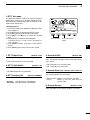
@1TX INDICATOR
Lights red while transmitting.
@2FUNCTION SWITCHES [F1]–[F5] (pp. 13, 14)
Push to select the function which is indicated on the
LCD display above each switch.
• The functions vary, depending on the selected menu
and the operating mode.
@3MENU SWITCH [MENU] (pp. 13, 14)
➥ Push to change the set of functions assigned to
switches ([F-1] to [F-5]).
• Toggles between the function menus, M1 (Menu 1)
and M2 (Menu 2).
➥ Hold down for 1 second to enter the Set mode.
Push to return to the previous screen display.
@4MODE SWITCHES
Push to select your desired operating mode. (p. 31)
• The built-in speech synthesizer announces the selected
mode when the “SPEECH [MODE] SW” item is set to
“ON” in the Set mode. (p. 87)
[SSB]
➥ P ush to alternately select the USB or LSB
modes.
• “USB” or “LSB” appears.
➥ In the SSB mode, hold down for 1 second to select the SSB data mode (USB-D, LSB-D).
• “D” appears in addition to “USB” or “LSB.”
➥ In the SSB data mode, push to return to the normal SSB mode.
[CW]
Push to alternately select the CW and CW-R (CW
reverse) modes.
• “CW” or “CW-R” appears.
PANEL DESCRIPTION
[RTTY]
Push to alternately select the RTTY and RTTY-R
(RTTY reverse) modes.
• “RTTY” or “RTTY-R” appears.
[AM/FM]
➥ Push to alternately select the AM or FM modes.
BK-IN SWITCH Operation (p. 63)
(Mode: CW)
Push to toggle the Break-in function between semi
break-in and full break-in, or to turn OFF the function.
✔ What is the Break-in function?
The Break-in function automatically switches between transmit and receive with your CW keying.
Using the Full Break-in function (QSK), you can
hear the receive frequency in-between keying.
• “AM” or “FM” appears.
➥ Hold down for 1 second to select the AM or FM
data mode (AM-D/FM-D).
• “D” appears in addition to “AM” or “FM.”
➥ In the data mode, push to return to the normal
AM or FM mode.
@5PREAMP•ATTENUATOR SWITCH [P.AMP•ATT]
PREAMP SWITCH Operation (p. 55)
Push to select one of two receive RF preamplifiers,
or to bypass them.
• “P. AMP ” is a wide dynamic range preamplifier. It is
most effective for the 1.8 to 21 MHz bands.
• “P. AMP ” is a high-gain preamplifier. It is most effective for the 24 to 50 MHz bands.
• No indicator appears when the preamplifiers are not selected.
✔ What is the preamplifier?
The preamplifier amplifies signals in the front end
to improve the S/N ratio and sensitivity. Select “P.
AMP ” or “P. AMP ” when receiving weak signals.
ATTENUATOR SWITCH Operation (p. 55)
➥ Hold down for 1 second to turn ON the attenuator.
• “ATT” appears when the attenuator is ON.
➥ Push to turn OFF the attenuator.
• “ATT” disappears.
✔ What is the attenuator?
The attenuator prevents a desired signal from being
distorted when very strong signals are near it, or
when very strong electromagnetic fields, such as
from a broadcasting station, are near your location.
@6VOX/BK-IN SWITCH [VOX/BK-IN]
VOX SWITCH Operation (p. 62)
(Mode: SSB/AM/FM)
➥ Push to turn the VOX function ON or OFF.
➥ Hold down for 1 second to display the “VOX”
screen. Push to return to the previous screen
display.
✔ What is the VOX function?
The VOX function (voice operated transmission)
automatically starts transmission when you speak
into the microphone; then automatically returns to
receive when you stop speaking.
1
@7COMPRESSOR SWITCH [COMP] (p. 64)
(Mode: SSB)
Push to turn the Speech Compressor function ON
or OFF.
1
2
• “COMP” appears when this function is ON.
3
@8MONITOR SWITCH [MONITOR] (p. 65)
Push to turn the Monitor function ON or OFF to listen to your own transmitted audio.
4
• “MONI” appears when this function is ON.
• In the CW mode, the CW sidetone can be heard, regardless of the [MONITOR] switch setting.
5
6
@9SPEECH SWITCH [SPEECH] (p. 33)
➥ Push to audibly announce the S-meter level and
the displayed frequency.
➥ Hold down for 1 second to audibly announce the
S-meter level, the displayed frequency, and the
operating mode.
7
8
9
• The S-Level announcement can be turned OFF in the
“SPEECH S-Level” item of the Set mode. (p. 87)
• When RIT and/or ∂TX are ON, the RIT/∂TX offset is
not included in the frequency announcement.
10
11
#0FILTER SWITCH [FILTER] (p. 57)
➥ Push to select one of three IF filter settings ( / /
).
12
• The selected filter passband width and shifting value
are displayed for 2 seconds on the LCD display.
13
➥ Hold down for 1 second to display the “FIL”
screen (Filter) to set the filter passband width.
Hold down for 1 second again to return to the
previous screen display.
14
15
#1TUNING DIAL [DIAL] (p. 26)
Rotate to change the operating frequency, select
the Set mode settings, etc.
16
17
#2LOCK SWITCH [LOCK] (p. 61)
Push to turn the Dial Lock function ON or OFF.
18
• This function electronically locks [DIAL].
• “
” appears when this function is ON.
19
20
21
4
1
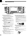
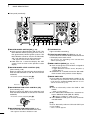
PANEL DESCRIPTION
■ Front panel (continued)
#83
#4 #5 #6 #7 #8
#9 $0
$1
$2
$3
$4
$5
$6
$7
#3TRANSMIT FREQUENCY CHECK SWITCH [XFC]
➥During split frequency or repeater operation,
hold down to listen to the transmit frequency.
(pp. 52, 56)
• While holding down this switch, the transmit frequency can be changed with [DIAL], keypad or
memo pad.
• When the Split Lock function is turned ON, push
[XFC] to cancel the Dial Lock function. (p. 67)
➥When the RIT function is turned ON, hold down
to listen to the displayed frequency (RIT is
temporarily cancelled). (p. 53)
➥When the ∂TX function is turned ON, hold down
to listen to the transmit frequency (including ∂TX
frequency offset). (p. 65)
#4UP/DOWN SWITCHES [Y]/[Z]
➥Push to change the operating channel. (p. 69)
➥Hold down to continuously change the operating
channel.
#5VFO EQUALIZE SWITCH [A=B] (p. 24)
H
old down for 1 second to equalize frequencies of
VFO A and B.
#6VFO SELECT SWITCH [A/B] (p. 24)
P
ush to select either VFO A or VFO B to display.
• “VFOA” or “VFOB” is displayed, depending on the selection.
#7SPLIT SWITCH [SPLIT]
➥Push to turn the Split function ON or OFF. (p. 66)
5
• The transmit frequency shifts from the receive frequency according to the “FM SPLIT Offset HF/50”
setting in the Set mode. (p. 86)
• The Quick Split function can be turned OFF in the
“Quick SPLIT” item of the Set mode. (p. 86)
• [GENE •] selects the general coverage band.
➥Pushing the same key two or three times calls
up other stacked frequencies in the frequency
band.
• Icom’s triple band stacking register memorizes three
frequencies in each frequency band.
KEYPAD Operation (p. 26)
After pushing [F-INP ENT], push the keys on the
keypad to enter a frequency. After entering, push
[F-INP ENT] to set the frequency.
• Example; to enter 14.195 MHz:
Push [F-INP ENT] [1] [4] [•] [1] [9] [5] [F-INP ENT].
#9PBT CLEAR SWITCH [PBT-CLR] (p. 59)
(Mode: SSB/CW/RTTY/AM)
➥Push to display the filter passband width and
shifting value for 2 seconds on the function display.
➥Hold down for 1 second to reset the PBT settings.
$0PASSBAND TUNING CONTROLS [TWIN-PBT]
(p. 59)
(Mode: SSB/CW/RTTY/AM)
Adjusts the receiver’s IF filter passband width using
the DSP circuit.
• “SPLIT” appears when the Split function is ON.
➥Hold down for 1 second to activate the Quick
Split function. (p. 67)
#8BAND KEYS/KEYPAD
BAND KEYS Operation (p. 25)
➥Push to select the operating band.
• Rotate this control or push [PBT-CLR] to display the
PBT settings (passband width and shifting value) for 1
second on the function display.
• Hold down [PBT-CLR] for 1 second to clear the PBT
settings.
• The PBT is adjustable in 50 Hz steps in the SSB, CW
and RTTY modes, and 200 Hz in the AM mode. In this
time, the shift value changes in 25 Hz steps in the SSB,
CW and RTTY modes, and 100 Hz in the AM mode.
• These controls function as an IF shift control.
PANEL DESCRIPTION
✔ What is the PBT control?
The PBT function electronically modifies the IF passband
width to reject interference. This transceiver uses the
DSP circuit for the PBT function.
PBT2
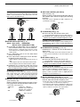
$3CW PITCH CONTROL [CW PITCH]
(outer control; p. 37)
Rotate to shift the received CW audio pitch and the
CW sidetone pitch without changing the operating
frequency.
PBT1
1
• The pitch can be adjusted from 300 to 900 Hz in approximately 5 Hz steps.
Higher pitch
–
+
Lower pitch
1
$4∂TX SWITCH [∂TX] (p. 65)
➥Push to turn the ∂TX function ON or OFF.
2
• Use the [RIT/∂TX] control to vary the ∂TX frequency.
➥Hold down for 1 second to shift the transmit frequency up or down by the ∂TX frequency shift.
High cut
Center
Low cut
$1NOTCH SWITCH [NOTCH] (p. 61)
(Mode =Auto notch : SSB/AM/FM
Manual notch: SSB/CW/RTTY/AM)
➥In the SSB and AM modes, push to toggle the
notch function between auto, manual and OFF.
• E ither the Auto or Manual Notch function can be
turned OFF in the “[NOTCH] SW” item of the Set
mode. (p. 88)
➥In the FM mode, push to turn the Auto Notch
function ON or OFF.
➥In the CW or RTTY mode, push to turn the Manual Notch function ON or OFF.
• “MNF” appears when the Manual Notch function is
ON.
• “ANF” appears when the Auto Notch function is ON.
• No icon appears when the Notch function is OFF.
➥Hold down for 1 second to switch the manual
filter characteristics from wide, mid and narrow
when the Manual Notch function is selected.
$2MANUAL NOTCH FILTER CONTROL [NOTCH]
(inner control; p. 61)
Rotate to adjust the notch frequency to reject an interfering signal when the Manual Notch function is ON.
• Notch filter center frequency:
SSB/RTTY
: –1040 Hz to +4040 Hz
CW
:C
W pitch freq. –2540 Hz to
CW pitch freq. +2540 Hz
AM
: –5060 Hz to +5100 Hz
Higher frequency
4
∂TX shifts the transmit frequency without shifting the receive frequency. This is useful for simple split frequency
operation in CW, etc.
5
6
$5CLEAR SWITCH [CLEAR] (pp. 53, 65)
Hold down for 1 second* to clear the RIT/∂TX frequency shift.
7
* When the “Quick RIT Clear” item in the Set mode is set
to “ON,” push momentarily to reset the frequency shift.
(p. 88)
8
9
$6RIT SWITCH [RIT] (p. 53)
➥Push to turn the RIT function ON or OFF.
10
• Use [RIT/∂TX] control to vary the RIT frequency.
➥Hold down for 1 second to shift the receive frequency up or down by the RIT frequency shift.
11
✔ What is the RIT function?
12
The RIT (Receiver Incremental Tuning) shifts the receive
frequency without shifting the transmit frequency.
This is useful for fine tuning stations calling you off-frequency or when you prefer to listen to slightly differentsounding voice characteristics, etc.
✔ What is the notch filter?
The notch filter is a narrow filter that eliminates unwanted
CW or AM carrier tones, while preserving the desired
voice signal. The DSP circuit automatically adjusts the
notch frequency to effectively eliminate unwanted tones.
3
✔ What is the ∂TX function?
13
14
15
$7RIT/∂TX CONTROL [RIT/∂TX] (pp. 53, 65)
When either or both the RIT/∂TX functions are ON,
rotate to adjust the RIT/∂TX frequency shift.
16
• Rotate the control clockwise to increase the frequency,
or counterclockwise to decrease the frequency.
• The frequency shift range is ±9.999 kHz in 10 Hz steps.
The control tunes in 1 Hz steps when the operating frequency readout is set to the 1 Hz step readout.
17
18
Shift high
19
20
Shift low
21
Lower frequency
6
1
PANEL DESCRIPTION
■ Front panel (continued)
$8 $9 %0 %1
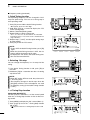
$8MEMO PAD-WRITE SWITCH [MP-W] (p. 74)
Push to write the displayed data into a memo pad.
%3TUNING STEP SWITCH [TS] (p. 27)
➥Push to turn quick tuning step ON or OFF.
• The five most recent entries remain in the memo pads.
• The memo pad capacity can be extended from 5 to
10 in the “Memopad Numbers” item in the Set mode.
(p. 87)
$9VFO/MEMORY SWITCH [VFO/MEMO]
➥ Push to switch between the VFO and Memory
modes. (p. 24)
➥ Hold down for 1 second to transfer the memory
contents to the displayed VFO. (p. 72)
%0MEMO PAD-READ SWITCH [MP-R] (p. 74)
Push to sequentially call up the contents from the
memo pads.
The 5 (or 10) most recently programmed frequencies and operating modes can be recalled, starting
from the most recent.
• The memo pad capacity can be extended from 5 to
10 in the “Memopad Numbers” item in the Set mode.
(p. 87)
%1MEMORY WRITE SWITCH [MW] (p. 70)
Hold down for 1 second to store VFO data into the
selected memory channel.
• This can be done in both the VFO and memory modes.
%2MEMORY CLEAR SWITCH [M-CLR] (p. 71)
In the Memory mode, hold down for 1 second to
clear the memory channel.
7
%2 %3
• The channel becomes a blank channel.
• This switch is disabled in the VFO mode.
• When the “” quick tuning icon is displayed above
the kHz digit, the frequency is changed in selected
quick tuning steps.
• When the quick tuning is OFF, the frequency is
changed in 10 Hz steps.
➥When the quick tuning is ON, hold down for
1 second to display the “TS” screen (Tuning
Step) to select the quick tuning step.
• 0.1, 1, 5, 9, 10, 12.5, 20, and 25 kHz steps are independently selectable for each operating mode.
➥When the quick tuning is OFF, hold down for
1 second to turn the minimum tuning step of
1 Hz ON or OFF.
PANEL DESCRIPTION
1
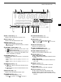
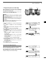
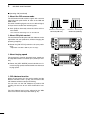
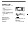
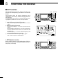
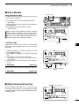
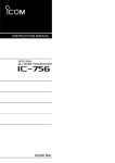
■ Rear panel
w
q
1
2
3
e
r
t
y
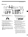
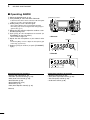
qDC POWER SOCKET [DC 13.8V] (p. 19)
Connect 13.8 V DC through the supplied DC power
cable.
Rear panel view
u
i
o
!0
4
5
ySTRAIGHT KEY JACK [KEY] (p. 16)
Connect a straight key or external electronic keyer
output using a standard 1⁄4 inch plug.
6
• To use the internal electronic keyer for CW operation,
connect to [ELEC-KEY] on the front panel. (p. 1)
7
(+)
8
(_)
wTUNER CONTROL SOCKET [TUNER] (p. 18)
Connect the control cable from an optional AH-4 hf/
50 mhz automatic antenna tuner.
eGROUND TERMINAL [GND] (p. 15)
Connect this terminal to a ground to prevent electrical shocks, TVI, BCI and other problems.
rANTENNA CONNECTOR 1 [ANT1] (p. 16)
tANTENNA CONNECTOR 2 [ANT2] (p. 16)
Connect a 50 ø antenna with a PL-259 plug connector.
When using an optional AH-4 hf/ 50 mhz automatic antenna tuner, connect it to the [ANT1]
connector. Connecting the AH-4 activates the internal antenna tuner for [ANT2] and deactivates
it for [ANT1].
9
uALC INPUT JACK [ALC] (p. 21)
When transmitting, goes to ground to control an external unit, such as a non-Icom linear amplifier.
10
11
iSEND CONTROL JACK [SEND] (p. 21)
Connect a ground when transmitting to control an
external unit, such as a non-Icom linear amplifier.
12
13
oACCESSORY SOCKET [ACC]
Connect control lines for external equipment such
as a linear amplifier, an automatic antenna selector/
tuner, a TNC for data communications, etc.
14
15
• See page 10 for socket information.
16
!0CI-V REMOTE CONTROL JACK [REMOTE]
(p. 17)
➥ Connect a PC, using the optional CT-17 ci-v
level converter, for external control of the transceiver.
➥ Use for transceive operation with another Icom
CI-V transceiver or receiver. When the transceive function is set to ON, changing the frequency, operating mode, etc. on the IC-7410
automatically changes those settings on other
Icom transceivers or receivers, and vice versa.
(p. 89)
17
18
19
20
21
8
1
PANEL DESCRIPTION
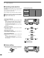
■ Rear panel (Continued)
!1
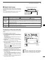
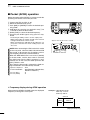
!1USB (Universal Serial Bus) CONNECTOR [USB]
Using a USB cable, connect a PC to do the following:
- Input modulation (p. 89)
- Remotely control the transceiver using CI-V commands (p. 101)
- Send the received audio to the PC
-S
end the decoded characters to the PC (p. 89)
About the USB driver:
The USB driver and the installation guide can be
downloaded from our website.
➥ http://www.icom.co.jp/world/index.html
The following items are required:
PC
• Microsoft® Windows® XP,
Microsoft® Windows Vista® or
Microsoft® Windows® 7 OS
• A USB 1.1 or 2.0 port
Other items
• USB cable (purchase separately)
• PC software (such as optional RS-BA1)
OTE: BE SURE to install the USB driver BEN
FORE connecting the USB cable between the
radio and the PC. This is because the USB driver
does not support the automatic recognition system.
About the modulation input:
Select “USB” in the Set mode item “DATA OFF
MOD” or “DATA MOD.” The modulation input level
from the USB jack can be set in the Set mode item
“USB MOD Level.” (p. 89)
9
!2
!2EXTERNAL SPEAKER JACK [EXT-SP] (p. 17)
Connect an external speaker (4 to 8 ø).
PANEL DESCRIPTION
1
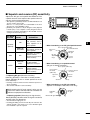
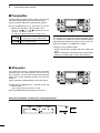
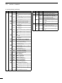
D ACC socket information
• ACC socket
ACC
PIN No.
NAME
8V
Regulated 8 V output.
2
GND
Connects to ground.
SEND*
An external unit controls
the transceiver.
When this pin goes low,
Input/out- the transceiver transmits.
put pin.
The transceiver outputs
a low signal to control an
external unit.
3
Rear panel view
i gray
o white
!0 black
!1 pink
!2 light
blue
!3 light
green
Color refers to
the cable strands
of the supplied
cable.
SPECIFICATIONS
Output voltage
Output current
1
13
9 10 11 12
5 6 7 8
1 2 3 4
q brown
w red
e orange
r yellow
t green
y blue
u purple
DESCRIPTION
: 8 V ± 0.3 V
: Less than 10 mA
———
Input voltage (High) : 2.0 V to 20.0 V
Input voltage (Low) : –0.5 V to +0.8 V
Current flow
: Max. 20 mA
Output voltage (Low) : Less than 0.1 V
Current flow
: Max. 200 mA
4
NC
5
BAND
Band voltage output.
Output voltage
: 0 V to 8 V
2
6
ALC
ALC voltage input.
Control voltage
Input impedance
: –3 V to 0 V
: More than 3.3 k˘
3
7
NC
8
13.8 V
9
NC
———
———
———
———
13.8 V output when power is ON.
Output current
: Less than 1 A
———
———
10
FSKK
Controls RTTY keying
“High” level
“Low” level
Output current
11
MOD
Modulator input.
Input impedance
Input level
12
AF
13
SQL S
AF detector output.
Output impedance
Fixed level, regardless of the [AF]
Output level
control position.
SQL open
Squelch output.
SQL closed
Grounded when squelch opens.
: More than 2.4 V
: Less than 0.6 V
: Less than 2 mA
: 10 k˘
: Approx. 100 mV rms
: 4.7 k˘
: 100 to 300 mV rms
: Less than 0.3 V/5 mA
: More than 6.0 V/100 µA
*When the SEND terminal controls an inductive load (such as a relay), a counter-electromotive force can cause
the transceiver’s malfunction or damage. To prevent this, we recommend adding a switching diode, such as an
“1SS133,” on the load side of the circuit to the counter-electromotive force absorption.
When the diode is added, a switching delay of the relay may occur. Be sure to check its switching action before
operation.
[Example]
ACC
socket
Switching diode
To a non-Icom
linear amplifier
Relay
i13.8 V
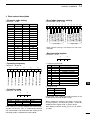
ACC 1
4
1
6
q FSKK
w GND
e SEND
r MOD
2
8
5
6
7
8
9
10
11
12
13
14
16
17
• When connecting the ACC conversion cable (OPC-599)
Connect to ACC socket
4
15
eSEND
!3
o !0 !1 !2
tyui
qwer
1
ACC 2
5
3
7
t AF
y SQL S
u 13.8 V
i ALC
4
2
1
6
q8V
w GND
e SEND
r BAND
18
5
19
3
7
t ALC
y NC
u 13.8 V
20
21
10
1
PANEL DESCRIPTION
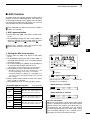
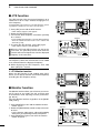
■ LCD display
q
w
e
r
t
!5
!4
!3
!2
!1
y
u
!0
o
i
qPOWER DOWN TRANSMISSION ICON (p. 98)
Appears when the output power is decreased by
the Reduced Power Transmission function.
uSPEECH COMPRESSOR ICON (p. 64)
Appears when the Speech Compressor function is
ON.
wTX ICON
Indicates the transmit frequency is displayed.
➥ “
” appears while the operating frequency is in
an amateur band.
➥ “
” appears while the operating frequency
is not in an amateur band. However, when the
“Band Edge Beep” item is set to “OFF” in the Set
mode (p. 85), “
” does not appear.
iFUNCTION DISPLAY (pp. 13, 14)
Shows the function of the function switches ([F-1] to
[F-5]), Set mode items and IF passband width.
eRX ICON
Indicates the receive frequency is displayed.
rFREQUENCY READOUT
➥ Displays the operating frequency.
• When the quick tuning icon “” is displayed, the frequency changes in kHz quick tuning steps. (p. 27)
• When the quick tuning icon “” is not displayed, the
frequency changes in 10 Hz or 1 Hz steps.
➥ When the Split function is ON, displays the receive frequency (VFO A or VFO B). (p. 66)
tMULTI-FUNCTION METER INDICATION
➥ Displays the signal strength while receiving.
➥ Displays the relative output power, ALC and
SWR or compression levels while transmitting.
(p. 33)
➥ When the Meter Peak Hold function is ON, the
peak level of a received signal strength or the
output power is displayed for approximately 0.5
seconds. (p. 60)
yVOX ICON (p. 62)
Appears when the VOX function is ON.
11
oVOICE SQUELCH CONTROL ICON (p. 76)
Appears when the VSC (Voice Squelch Control)
function is ON.
!0TONE SQUELCH ICONS
(Mode: FM)
➥ “TONE” appears when the Repeater Tone function is ON. (p. 52)
➥ “TSQL” appears when the Tone Squelch function
is ON. (p. 50)
!1SPLIT READOUT (pp. 66, 67)
When the Split function is ON, displays the transmit
frequency (VFO A or VFO B).
!2MEMORY CHANNEL READOUT (p. 69)
Displays the selected memory channel.
!3SELECT MEMORY CHANNEL ICON (p. 80)
Appears when the selected memory channel is set
as a select memory channel.
!4BLANK MEMORY ICON (pp. 69, 71)
Appears when the selected memory channel is
blank.
!51⁄4 TUNING DIAL SPEED ICON (p. 27)
(Mode: SSB-D/CW/RTTY)
Appears when the tuning dial speed is set so that
one rotation is equal to 1⁄4 of the normal rotation.
PANEL DESCRIPTION
@0
!9
!8
!7
1
!6
#2
#1
#0
1
@1
2
@2
3
@3
@4
@5
@6 @7 @8
@9
4
5
!6DIAL LOCK ICON (p. 61)
Appears when the Dial Lock function is ON.
@4ATTENUATOR ICON (p. 55)
Appears when the Attenuator is ON.
6
!7SPLIT ICON (p. 66)
Appears when the Split function is ON.
@5AGC ICONS (p. 56)
Displays the selected AGC time constant.
7
!8MODE ICONS (p. 31)
Displays the selected operating mode.
• “D” appears when the SSB data, AM data or FM data
mode is selected.
!9ANTENNA TUNER ICONS (p. 83)
➥ “
” appears when the antenna tuner is ON;
“
” blinks during tuning.
➥ “
” appears when the optional AH-4 external
antenna tuner is connected to the [ANT1] connector, and [ANT1] is selected.
@0ANTENNA ICONS (p. 82)
Displays which antenna connector is selected for
HF/50 MHz.
• “ANT1” appears when the [ANT1] connector is selected.
• “ANT2” appears when the [ANT2] connector is selected.
@1BREAK-IN ICONS (p. 63)
➥ “F BK-IN” appears when the Full Break-in function is ON.
➥ “BK-IN” appears when the Semi Break-in function is ON.
@2MONITOR ICON (p. 65)
Appears when the Monitor function is ON.
@3PREAMP ICONS (p. 55)
Appears when a preamplifier is ON.
• “P. AMP
” for preamp 1; “P. AMP
• “ ” for fast AGC; “ ” for mid AGC; “ ” for slow AGC;
“-OFF” for AGC OFF.
@6DSP FILTER ICONS (p. 57)
Displays the selected IF filter.
@7NOISE BLANKER ICON (p. 60)
Appears when the Noise Blanker is ON.
@8NOISE REDUCTION ICON (p. 61)
Appears when the Noise Reduction is ON.
@9NOTCH ICONS (p. 61)
(Mode: SSB/CW/RTTY/AM)
➥ “MNF” appears when the Manual Notch function
is ON.
(Mode: SSB/AM/FM)
➥ “ANF” appears when the Automatic Notch function is ON.
8
9
10
11
12
13
14
15
16
#0MEMORY ICON (p. 24)
Appears when the memory mode is selected.
17
#1VFO ICONS (p. 24)
Appears when VFO A or VFO B is selected.
18
#2RIT/∂TX ICONS (pp. 53, 65)
➥ “RIT” appears when the RIT function is ON.
➥ “∂TX” appears when the ∂TX function is ON.
➥ Shows the frequency shift of the RIT or ∂TX
function.
20
19
21
” for preamp 2.
12
1
PANEL DESCRIPTION
■ Function display
Push [MENU] to toggle between M1 (Menu 1) and M2
(Menu 2).
• The set of functions assigned to the function switches
changes, according to the selected menu and operating mode.
Push to select the functions displayed above switches
([F-1] to [F-5]).
D M1 (Menu 1)
D Function keys on M1 (Menu 1)
(Mode: SSB)
AGC KEY [AGC](F-1) (p. 56)
(Mode: SSB/CW/RTTY/AM/FM)
➥ Push to select the time constant of the AGC circuit.
➥ H old down for 1 second to display the “AGC”
screen.
AGC
TBW
SCP
(Mode: SSB-D)
AGC
1⁄4
SCP
1⁄4
KEY
SCP
1⁄4
RTTY
SCP
(Mode: RTTY)
AGC
1⁄4 TUNING FUNCTION KEY [1⁄4](F-3) (p. 27)
(Mode: SSB-D/CW/RTTY)
Push to turn the 1⁄4 Tuning function ON or OFF.
• “
(Mode: CW)
AGC
• Functions vary, depending on the operating mode.
TRANSMISSION BANDWIDTH KEY [TBW](F-4)
(p. 64)
(Mode: SSB)
➥ Push to display the selected transmission bandwidth.
➥ Hold down for 1 second to select the transmission
bandwidth.
(Mode: AM)
AGC
SCP
(Mode: FM)
AGC
TON
SCP
” is displayed when the 1⁄4 Tuning function is ON.
• Wide (WIDE), mid (MID) and narrow (NAR) bandwidths
are selectable.
MEMORY KEYER MENU KEY [KEY](F-4) (p. 38)
(Mode: CW)
Push to display the “KEY” screen (Memory Keyer) or
the “SEND” screen (Keyer Send), depending on the
“KEYER 1st Menu” setting in the Set mode (p. 88).
RTTY MENU KEY [RTTY](F-4) (p. 45)
(Mode: RTTY)
Push to display the “RTTY” screen.
TONE SQUELCH KEY [TON](F-4) (p. 50)
(Mode: FM)
➥ Push to select a tone function between subaudible
(repeater) tone and tone squelch.
➥ Hold down for 1 second to display the “TON” screen
(Tone) of the selected tone function.
BAND SCOPE FUNCTION KEY [SCP](F-5) (p. 54)
(Mode: SSB/CW/RTTY/AM/FM)
Push to display the “SCP” screen (Band Scope).
13
PANEL DESCRIPTION
D M2 (Menu 2)
SCAN
MEM
1
D Function keys on M2 (Menu 2)
SWR
TCON
VSC
SCAN KEY [SCAN](F-1) (p. 75)
(Mode: SSB/CW/RTTY/AM/FM)
Push to display the “SCAN” screen.
MEMORY NAME KEY [MEM](F-2) (p. 73)
(Mode: SSB/CW/RTTY/AM/FM)
Push to display the “MEM” screen (Memory Name
Edit).
SWR GRAPH FUNCTION KEY [SWR](F-3) (p. 68)
(Mode: SSB/CW/RTTY/AM/FM)
Push to display the “SWR” screen.
1
TONE CONTROL SET MODE KEY [TCON](F-4)
(p. 90)
(Mode: SSB/CW/RTTY/AM/FM)
Push to enter the Tone Control Set mode.
3
VSC FUNCTION KEY [VSC](F-5) (p. 76)
(Mode: SSB/AM/FM)
Push to turn the VSC function (Voice Squelch Control)
ON or OFF.
• “
” appears when the VSC function is ON.
2
4
5
6
7
8
9
10
11
12
13
14
15
16
17
18
19
20
21
14
2
INSTALLATION AND CONNECTIONS
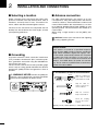
■ Selecting a location
■ Antenna connection
elect a location for the transceiver that allows adeS
quate air circulation, free from extreme heat, cold, or
vibrations, and away from TV sets, TV antenna elements, radios and other electromagnetic sources.
For radio communications, the antenna is of critical importance, along with output power and receiver
sensitivity. Select a well-matched 50 ø antenna and
coaxial cable feedline. We recommend 1.5:1 or better of Voltage Standing Wave Ratio (VSWR) on your
operating bands. The transmission line should be a
coaxial cable.
When using a single antenna, use the [ANT1] connector.
he base of the transceiver has adjustable feet for
T
desktop use. Set the feet to one of two angles, to meet
your operating preference.
CAUTION: Protect your transceiver from lightning
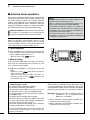
by using a lightning arrestor.
Antenna SWR
■ Grounding
o prevent electrical shock, television interference
T
(TVI), broadcast interference (BCI) and other problems, ground the transceiver using the GROUND terminal on the rear panel.
For best results, connect the heaviest possible gauge
wire or strap to a long ground rod. Make the distance
between the [GND] terminal and ground as short as
possible.
R WARNING! NEVER connect the [GND] ter-
Each antenna is tuned for a specified frequency
range and the SWR usually increases outside the
range. When the SWR is higher than approx. 2.0:1,
the transceiver automatically reduces the TX power
to protect the final transistors. In that case, an
antenna tuner is useful to match the transceiver and
antenna. Low SWR allows full power for transmitting. The IC-7410 has an SWR meter to continuously
monitor the antenna SWR.
PL-259 CONNECTOR INSTALLATION EXAMPLE
q
30 mm
minal to a gas or electric pipe, since the connection
could cause an explosion or electric shock.
Coupling ring
w
10 mm (tin here)
10 mm
tin
Slide the coupling ring
down. Strip the cable
jacket and tin the shield.
Strip the cable as
shown at left. Tin the
center conductor.
1–2 mm
[GND]
e
r
solder solder
Slide the connector
body on and solder it.
Screw the coupling
ring onto the connector body.
30 mm (1.18 in) 10 mm (0.39 in) 1–2 mm (0.04–0.08 in)
15
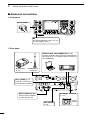
INSTALLATION AND CONNECTIONS
2
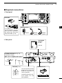
■ Required connections
D Front panel
ELEC-KEY
(dot)
(com)
(dash)
1
2
MICROPHONES (p. 22)
A straight key can be connected. However, “Straight
key” must be selected in
the “Keyer Type” item of the
Keyer Set mode. (p. 43)
3
HM-36
SM-30
(option)
SM-50
(option)
4
5
6
D Rear panel
DC POWER
SUPPLY
(p. 19)
7
8
9
PS-126
10
11
12
HF/50MHz ANTENNA 1, 2 (p. 15)
Connection example:
[ANT 1] for 1.8–18 MHz bands antenna
[ANT 2] for 21–28 MHz bands antenna
13
14
15
16
17
GROUND (p. 15)
STRAIGHT KEY
Use the heaviest possible
gauge wire or strap and
make the connection as
short as possible.
Grounding prevents electrical shocks, TVI and
other problems.
18
19
20
21
+
_
16
2
INSTALLATION AND CONNECTIONS
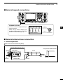
■ Advanced connections
D Front panel
HEADPHONES
MIC
The AFSK modulation signal can also
be input to [MIC]. (p. 92)
D Rear panel
REMOTE JACK, USB CONNECTOR (p. 101)
Used for computer control and transceive operation.
The optional CT-17 is required when connecting a
PC to [REMOTE].
with
AH-4 (option)
(p. 18)
AH-2b (option)
or long wire
[ALC], [SEND] (p. 21)
Used for connecting a
non-Icom linear amplifier.
[ANT 1], [ANT 2] (p. 82)
Connect a linear amplifier,
antenna selector, etc.
EXTERNAL SPEAKER
(p. 111)
ACC SOCKET
(p. 10)
17
SP-23
(option)
INSTALLATION AND CONNECTIONS
2
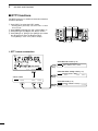
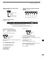
■ External keypad connections
EXTERNAL KEYPAD
Connect an external keypad for keyer
memory control.
When using a external keypad, set
the “External Keypad” item to “KEYER
SEND” in the Set mode. (p. 88)
4.7 kø 2.2 kø 1.5 kø 1.5 kø
±5%
±5%
±5%
±5%
1
1
2
S4
(M4)
S3
(M3)
S2
(M2)
EXTERNAL KEYPAD
S1
(M1)
2
To pin e
3
To pin y
7
6
8
4
5
[MIC]
(Front view)
3
4
5
6
■ External antenna tuner connection
7
D Connecting the AH-4
8
The AH-4 must be connected to [ANT1].
9
Coaxial cable (from the AH-4)
Long wire or optional AH-2b
[ANT1]
Transceiver
AH-4
10
11
12
13
[TUNER]
Ground
Control cable
Ground
14
15
16
17
18
19
20
21
18
2
INSTALLATION AND CONNECTIONS
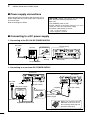
■ Power supply connections
When operating the transceiver with AC power, use a
power supply with 13.8 V DC output and a capacity of
at least 23 Amps.
Refer to the diagrams below.
CAUTION: Before connecting the DC power
cable, check the following important items.
Make sure:
• The [POWER] switch is OFF.
• Output voltage of the power source is 12–15 V
when you use a non-Icom power supply.
• DC power cable polarity is correct.
Red : Positive + terminal
Black: Negative _ terminal
■ Connecting to a DC power supply
D Connecting to the PS-126 DC POWER SUPPLY
AC outlet
PS-126
To [DC 13.8V]
To disconnect
q
w
AC cable
Transceiver
Ground
DC power cable
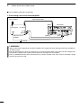
D Connecting to a non-Icom DC POWER SUPPLY
Transceiver
For European versions
Transceiver
AC outlet
Ground
To [DC 13.8V]
A DC power supply
13.8 V;
at least 23 A
+
To [GND]
To disconnect
q
_
w
AC cable Red
Connect to
power supply
Black
Supplied DC power cable
19
To [DC 13.8V]
When you install the ferrite
EMI filter, make sure the cables at the top of the loop are
parallel to each other.
INSTALLATION AND CONNECTIONS
2
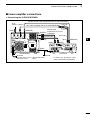
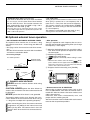
■ Linear amplifier connections
D Connecting the IC-PW1/PW1EURO
To an
antenna [ACC1]
[ANT]
Remote control cable (supplied with the IC-PW1/PW1EURO)
ACC cable (supplied with the IC-PW1/PW1EURO)
[REMOTE]
7-pin side
Coaxial cable
(supplied with the IC-PW1/
[INPUT1] PW1EURO)
Coaxial cable*
[INPUT2]
[ACC]
[ANT1]
EXCITER
1
1&2
1
OPC-599
[REMOTE]
[ANT2]
AC outlet
(Non-European versions: 100–120/200–240 V
European version
: 230 V)
3
4
[GND]
IC-PW1/EURO
2
5
[GND]
Ground
Transceiver
* I f necessary, purchase separately, and connect to [INPUT2].
6
7
8
9
10
11
12
13
14
15
16
17
18
19
20
21
20
2
INSTALLATION AND CONNECTIONS
■ Linear amplifier connections (Continued)
D Connecting a non-Icom linear amplifier
50 ø coaxial cable
To an antenna
[ANT1]
RF OUTPUT
GND
Transceiver
RF INPUT
ALC
SEND
Non-Icom linear
amplifier
[GND]
[ALC]
[SEND]
Ground
R WARNING!
• Set the transceiver output power and linear amplifier ALC output level after referring to the linear amplifier instruction manual.
• The ALC input level must be in the range 0 V to –3 V. The transceiver does not accept a positive voltage. Nonmatched ALC and RF power settings could overheat or damage the linear amplifier.
• The IC-7410 SEND terminal (ACC connector pin 3) is rated at 16 V/0.5 A DC. If this value is exceeded, a larger
external relay must be used.
21
INSTALLATION AND CONNECTIONS
2
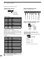
■ Microphone connector information
(Front panel view)
[MIC]
Pin No.
i AF output (varies with [AF])
u GND
(Microphone ground)
q Microphone input
w +8 V DC output
y GND (PTT ground)
e Frequency up/down
t PTT
w
e
r
r Squelch switch
FUNCTION
DESCRIPTION
+8 V DC output
Max. 10 mA
Frequency up
Ground
Frequency down
Ground through 470 ˘
Squelch open
“Low” level
Squelch closed
“High” level
AUTION: DO NOT short pin 2 to ground as this
C
can damage the internal 8 V regulator. A DC voltage is applied to pin 1 for microphone operation.
Use caution when using a non-Icom microphone.
2
3
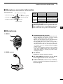
■ Microphones
4
D HM-36
q
qUP/DOWN SWITCHES [UP]/[DN]
Push to change the frequency or memory channel.
q
w
w
D SM-50 (option)
• While holding down, the frequency or memory channel
number continuously increases or decreases.
• While in the split frequency mode, and holding down
[XFC], push to change the transmit frequency.
• The [UP]/[DN] switch can be used as a key paddle if
the “MIC Up/Down Keyer” item is set to “ON” in the
Keyer Set mode. In such case, the frequency and memory channel cannot be changed using the [UP]/[DN]
switches. (p. 43)
• You can set the dot-dash polarity of the [UP]/[DN]
switch in the “Paddle Polarity” item in the Keyer Set
mode. When “Normal” is selected, [UP] sends a dash,
and [DN] sends a dot.
wPTT SWITCH
Hold down to transmit; release to receive.
ePTT LOCK SWITCH (available on only the SM-50)
Push to toggle between transmit and receive.
rLOW CUT SWITCH (available on only the SM-50)
Push to cut out the low frequency components of
input voice signals.
q
r
q
w
r
w
1
e
e
5
6
7
8
9
10
11
12
13
14
15
16
17
18
19
20
21
22
3
BASIC OPERATION
■ Before first applying power
Before turning ON your transceiver for the first time,
make sure all connections required for your system
are complete by reviewing them in Section 2 of this
manual.
After all connections have been made, set controls
and switches as shown in the illustration below.
[NR]
: Max. CCW
[RF PWR]
: Max. CW
[NOTCH]
: 12 o’clock
[MIC]
: 12 o’clock
[CW PITCH]
: 12 o’clock
[AF]
: Max. CCW
[RF/SQL]
: 12 o’clock
[KEY SPEED]
: 10–12 o’clock
CW : Clockwise
CCW : Counterclockwise
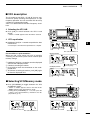
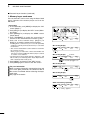
■ Turning ON (CPU resetting)
First time to Power ON:
Reset the transceiver using the following procedure.
esetting CLEARS all the programmed contents in
R
the memory channels, and returns all the programmed items in the Set mode to their default settings.
[POWER]
[M-CLR] [F-INP ENT]
qMake sure the transceiver’s power is OFF.
wWhile holding down both [F-INP ENT] and [M-CLR],
push [POWER] to turn ON the transceiver.
• The CPU is reset.
• The transceiver displays “ALL CLEAR,” then displayes
its initial VFO frequency when resetting is complete.
eChange the Set mode settings to suit your operating needs. (p. 85)
Normal Power ON:
Push [POWER] to turn ON the transceiver.
Ω ALL CLEAR ≈
Power OFF:
Hold down [POWER] for 1 second to turn OFF the
transceiver.
M1
AGC
23
TBW
SCP
BASIC OPERATION
3
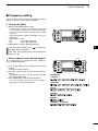
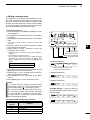
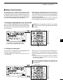
■ VFO description
The IC-7410 has two VFOs; “A” and “B,” that are convenient for quickly selecting two frequencies, or split
frequency operation. You can use either VFO to call up
a frequency and operating mode.
VFO is an abbreviation of Variable Frequency Oscillator.
[A=B] [A/B]
D Selecting the VFO A/B
➥ P ush [A/B] to switch between the VFO A and
VFO B.
1
• “VFOA” or “VFOB” appears when the VFO is selected.
D VFO equalization
2
➥ Hold down [A=B] for 1 second to equalize the data
in both VFOs.
3
4
• Three beeps sound when the equalization is complete.
CONVENIENT!
Use two VFOs as quick memories:
When you find a new station, but wish to continue
searching, the dual VFO system can be used for quick
memory storage.
q Hold down [A=B] for 1 second to store the displayed
data into the undisplayed VFO.
wContinue searching for stations.
e Push [A/B] to show the stored data on the undisplayed VFO.
r To continue searching for stations, push [A/B] again
to show the displayed VFO.
The selected VFO icon
Displayed
VFO
M1
AGC
TBW
SCP
5
6
7
8
Undisplayed
VFO
M1
AGC
q Hold down [A=B]
e Push [A/B]
TBW
SCP
9
10
11
12
■ Selecting VFO/Memory mode
13
M1
AGC
➥ Push [VFO/MEMO] to toggle between the VFO
and Memory modes.
TBW
SCP
[VFO/MEMO]
• “VFOA” or “VFOB” appears when in the VFO mode.
“MEMO” appears when in the Memory mode.
• Holding down [VFO/MEMO] for 1 second copies the
contents of the selected Memory channel into the displayed VFO. (p. 72)
14
15
16
17
18
19
20
21
The selected VFO icon
M1
AGC
The memory icon
M1
TBW
SCP
AGC
TBW
SCP
24
3
BASIC OPERATION
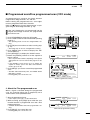
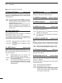
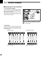
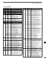
■ Selecting a frequency band
The triple band stacking register provides three memories for each band key to store frequencies and
operating modes.
This function is convenient when you operate three operating modes on one frequency band. For example,
one register can be used for a CW frequency, another
for an SSB frequency and the other one for an RTTY
frequency.
Band keys
See the table below for a list of the bands available
and the default settings for each band.
BAND
REGISTER 1
REGISTER 2
REGISTER 3
1.8
MHz*1
1.900000 MHz CW
1.910000 MHz CW
1.915000 MHz CW
3.5
MHz*1
3.550000 MHz LSB
3.560000 MHz LSB
3.580000 MHz LSB
7.050000 MHz LSB
7.060000 MHz LSB
7.020000 MHz CW
10.120000 MHz CW
10.130000 MHz CW
10.140000 MHz CW
14 MHz
14.100000 MHz USB
14.200000 MHz USB
14.050000 MHz CW
18 MHz
18.100000 MHz USB
18.130000 MHz USB
18.150000 MHz USB
21 MHz
21.200000 MHz USB
21.300000 MHz USB
21.050000 MHz CW
24 MHz
24.950000 MHz USB
24.980000 MHz USB
24.900000 MHz CW
28 MHz
28.500000 MHz USB
29.500000 MHz USB
28.100000 MHz CW
50.100000 MHz USB
50.200000 MHz USB
51.000000 MHz FM
15.000000 MHz USB
15.100000 MHz USB
15.200000 MHz USB
7 MHz
10
50
MHz*1
MHz*1
General*2
*1 The default frequency and mode settings are differ depending on the version. Above list shows the USA version’s.
*2 [GENE •] selects the general coverage band.
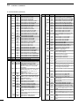
D Using the band stacking registers.
qPush a band key ([1.8 1] to [50 0] or [GENE •]).
[Example]: 14 MHz frequency band
• The previously selected frequency and operating mode
are called up as the first band stacking register of that
frequency band.
wSelect a frequency and an operating mode, and
then push the band key.
• The selected frequency and mode are memorized as
that frequency band’s first band stacking register.
eSelect another frequency and operating mode, and
then push the band key.
• The selected frequency and mode are memorized as
that frequency band’s second band stacking register.
Push
M1
AGC
TBW
SCP
rSelect another frequency and operating mode, and
then push the band key.
• The selected frequency and mode are memorized as
that frequency band’s third band stacking register.
tThe first band stacking register set in step w, is
called up.
25
• When the frequency band key is pushed, the memorized triple band stacking registers are sequentially
called up.
Push
M1
AGC
DUP
COMP TBW
DUP
COMP TBW
Push
M1
AGC
SCP
SCP
BASIC OPERATION
3
■ Frequency setting
You can select the transceiver’s frequency by using
[DIAL], or you can enter it using the keypad.
D Tuning with [DIAL]
qSelect the desired frequency band.
Band keys
• Push a band key 1–3 times. Three different frequencies
on each frequency band can be selected with the band
key. (See the previous page “Using the band stacking
registers.”)
• The default tuning step differs, depending on the operating mode.
SSB/CW/RTTY: 10 Hz
AM
: 1 kHz (“Z” is displayed)
FM
: 10 kHz (“Z” is displayed)
1
[DIAL]
wRotate [DIAL] to set the desired frequency.
2
3
If the Dial Lock function is ON, “
” is displayed,
and [DIAL] does not function.
In this case, push [LOCK] to turn OFF the Dial Lock
function. (p. 61)
4
5
D Direct frequency entry with the keypad
Keypad
he transceiver has a keypad for direct frequency
T
entry, as described below.
6
7
qPush [F-INP ENT] to enter frequencies with the
keypad.
8
9
• All frequency digits disappear.
wPush the numeric keys to input the desired frequency.
• Push [GENE •] to input a “.” (decimal point) between the
MHz digits and kHz digits.
ePush [F-INP ENT] to set the input frequency.
• To cancel the input, push any key such as [MW] or
[M-CLR], before pushing [F-INP ENT].
[EXAMPLE]
14.025 MHz
10
11
18.0725 MHz
12
706 kHz
13
14
5.100 MHz
15
7.000 MHz
16
21.280 MHz ➪ 21.245 MHz
17
18
19
20
21
26
3
BASIC OPERATION
■ Frequency setting (continued)
D Quick Tuning function
[F-3]
[TS]
The operating frequency can be changed in “kHz”
steps for quick tuning. You can set a tuning step in
each operating mode.
qPush [TS] to turn ON the Quick Tuning function.
• “Z” appears above the 1 kHz digit.
wHold down [TS] for 1 second to display the “TS”
screen (Tuning Step).
eSelect a desired operating mode.
rRotate [DIAL] to select a tuning step.
[DIAL]
Mode selection
Appears
• 0.1, 1, 5, 9, 10, 12.5, 20, and 25 kHz are selectable.
• Hold down [F-3] for 1 second to reset to the default setting, if desired.
tRepeat steps e and r to select quick tuning steps
for other modes.
yPush [TS] to exit the “TS” screen.
OTE:
N
• To turn OFF the Quick Tuning function, push [TS]
again.
• When the Quick Tuning function is OFF, the frequency will be changed in 10 Hz steps.
• To display the “TS” screen, the Quick Tuning function must be turned ON first.
SSB
1kHz
TS
[TS]
D Selecting 1 Hz step
You can change the frequency in 1 Hz steps for fine
tuning.
qIf the Quick Tuning function is ON, push [TS] to
turn OFF.
wHold down [TS] for 1 second to turn the 1 Hz tuning
step ON or OFF.
[DIAL]
Appears
NOTE:
• When RIT and/or ∂TX are used, they also tune in
1 Hz tuning steps.
• The frequency changes in 50 Hz steps when the
[UP]/[DN] switches of the microphone are used
for frequency tuning (if the Quick Tuning function
is OFF.)
M1
D 1⁄4 Tuning
Step function
AGC
TBW
SCP
(Mode: SSB-D/CW/RTTY)
The dial speed is reduced to 1⁄4 of the normal speed
when the 1⁄4 Tuning Step function is ON, for finer tuning control.
qPush [MENU] to display the “M1” screen (Menu 1).
wPush [1⁄4](F-3) to turn the 1⁄4 Tuning Step function
ON or OFF.
• “
[MENU]
[1⁄4]
Appears
” appears when the 1⁄4 Tuning Step function is ON.
27
M1
AGC
1/4
SCP
BASIC OPERATION
D Auto Tuning Step function
3
[∫] [√]
When you rotate [DIAL] rapidly, the tuning speed can
automatically accelerate, depending on the “MAIN
DIAL Auto TS” setting in the Set mode.
qHold down [MENU] for 1 second to enter the Set
mode.
wPush [Y](F-1) or [Z](F-2) to select “MAIN DIAL
Auto TS.”
eRotate [DIAL] to select the HIGH or LOW tuning
speed acceleration, or to turn OFF the function.
• HIGH: When the tuning step is set to 1 kHz or
smaller steps, the tuning speed is approximately five times faster.
When the tuning step is set to 5 kHz or
larger steps, the tuning speed is approximately two times faster. (default)
• LOW: Approximately two times faster.
• OFF : Turns the function OFF.
[MENU]
[DIAL]
SET M A I N D I A L A u t o T S
Ù 26 Ú
HIGH
HIGH (default)
1
2
3
4
• Hold down [F-3] for 1 second to reset to the default setting, if desired.
5
rPush [MENU] to save, and exit the Set mode.
6
7
D About the 5 MHz frequency band operation (only USA version)
Operation on the 5 MHz band is allowed on 5 discrete
frequencies and must adhere to the following:
• The USB mode
• Maximum of 50 watts ERP (Effective Radiated Power)
• 2.8 kHz bandwidth
It’s your responsibility to set all controls so that transmission in this band meets the stringent conditions
under which amateur operations may use these frequencies.
OTE: We recommend that you store these freN
quencies, mode and filter settings into memory
channels for easy recall.
*T he FCC specifies center frequencies on the
5 MHz band. However, the transceiver displays carrier frequency. Therefore, tune the transceiver to
1.5 kHz below the specified FCC channel center
frequency.
8
Transceiver Displayed
Frequency*
FCC Channel
Center Frequency*
5.33050 MHz
5.33200 MHz
5.34650 MHz
5.34800 MHz
5.36650 MHz
5.36800 MHz
5.37150 MHz
5.37300 MHz
5.40350 MHz
5.40500 MHz
To assist you in operating the 5 MHz band within the
rules specified by the FCC, transmission is illegal on
any 5 MHz band frequency other than the five frequencies shown in the table above.
9
10
11
12
13
14
15
16
17
18
19
20
21
28
3
BASIC OPERATION
■ Frequency setting (continued)
D Band edge warning beep
You can hear a beep tone when you tune in or out of
an amateur band’s frequency range. A regular beep
sounds when you tune into a range, and an lower tone
error beep sounds when you tune out of a range.
Also, the TX icon appears if the selected frequency is
in or out of an amateur band, when an option other
than “OFF” is selected.
• “
” is displayed, instead of the regular TX icon “
,”
while the operating frequency is out of an amateur band.
qHold down [MENU] for 1 second to enter the Set
mode.
wPush [Y](F-1) or [Z](F-2) to select “Band Edge
Beep.”
eRotate [DIAL] to select the desired band edge warning beep setting.
• OFF
: Band edge beep is OFF.
• ON (Default) : When you tune into or out of
the default amateur band’s frequency range, a beep sounds.
(default)
• ON (User)
: When you tune into or out of a user programmed amateur
band’s frequency range, a beep
sounds.
• ON (User) & TX: When you tune into or out of a user programmed amateur
band’s frequency range, a beep
sounds. Also transmission is inhibited outside the programmed
range.
[∫] [√]
[MENU]
[DIAL]
SET B a n d E d g e B e e p
Ù
6 Ú
ON(Default)
ON (Default)
• Hold down [F-3] for 1 second to reset to the default setting, if desired.
rPush [MENU] to save, and exit the Set mode.
The beep output level can be set in the “Beep Level”
item of the Set mode. (p. 85)
About the user band edge frequencies
When “ON (User)” or “ON (User) & TX” is selected in
the “Band Edge Beep” item, a total of 30 band edge
frequencies can be programmed in the “User Band
Edge” item. See the next page for details.
If “OFF” or “ON (Default)” is selected, the “User Band
Edge” item does not appear in the Set mode.
SET B a n d E d g e B e e p
Ù
6 Ú
ON(User)
ON (User) selection
SET U s e r B a n d E d g e
Ù
7 Ú
DEF
EDT
[User Band Edge] item
29
BASIC OPERATION
D Programming the user band edge
[∫] [√] [Ω≈]
3
Keypad
When “ON (User)” or “ON (User) & TX” is selected in
the “Band Edge Beep” item, the “User Band Edge”
item appears in the Set mode.
A total of 30 band edge frequencies can be programmed in the “User Band Edge” item.
NOTE:
• All frequency ranges are set to default, so you
should delete or change them to add the desired
band edge frequency.
• Program each channel from left to right and each
frequency must be higher than the preceding frequency.
• The frequency that is duplicated, or out of an amateur band, cannot be programmed.
qHold down [MENU] for 1 second to enter the Set
mode.
wPush [Y](F-1) or [Z](F-2) to select “Band Edge
Beep.”
eRotate [DIAL] to select either “ON (User)” or “ON
(User) & TX.”
rPush [Z](F-2) to select “User Band Edge.”
tPush [EDT](F-4) to display the “EDG” screen (Band
Edge Program).
yPush [Y](F-1) or [Z](F-2) to select the desired band
edge.
• Holding down [Y](F-1) or [Z](F-2) continuously selects
the band edges.
• Push [Ω ≈](F-3) to select the upper or lower band edge
frequency entry status.
• Hold down [DEL](F-5) for 1 second to delete the selected band edge.
• Push [INS](F-4) to insert a new blank band edge.
[MENU]
[INS] [DEL]
[DIAL]
1
2
3
SET B a n d E d g e B e e p
Ù
6 Ú
ON(User)
ON (User) setting in the
“Band Edge Beep” item
4
5
6
SET U s e r B a n d E d g e
Ù
7 Ú
DEF
EDT
7
“User Band Edge” item
EDG
Ù
1
1.600.000Ω≈
Ú
8
29.999.999
INS
DEL
“EDG” screen
9
10
11
uInput the desired frequency with the keypad, then
push [F-INP ENT].
12
13
• Push [GENE •] to input decimal point (“.”) between the
MHz and kHz digits.
iPush [MENU] to save.
oPush [MENU] again to exit the Set mode.
To reset the band edge frequencies
If you want to reset the band edge frequencies to their
default (initial) settings, select the “User Band Edge”
item, then hold down [DEF](F-3) for 1 second.
The band edge initialize screen appears, then hold
down [YES](F-4) for 1 second to reset all band edge
frequency settings to their default settings.
14
15
16
SET U s e r B a n d E d g e
Ù
7 Ú
DEF
EDT
17
“User Band Edge” item
18
Hold down
SET I n i t i a l i z e
Edges?
YES
NO
Band edge initialize screen
Hold down
SET U s e r B a n d E d g e
Ù
7 Ú
DEF
EDT
19
20
21
30
3
BASIC OPERATION
■ Operating mode selection
The usable operating modes in the IC-7410 are listed
to the right.
You can select the desired operating mode by pushing the appropriate mode switch.
See the diagram to the right for the order of selection.
When the data mode is selected, you can mute the
microphone signals, depending on the “DATA MOD”
setting in the Set mode (p. 89).
• Usable operating modes
Mode switch
Operating mode
[SSB]
USB
USB Data
LSB
LSB Data
[CW]
CW
CW Reverse
[RTTY]
RTTY
RTTY Reverse
AM
AM Data
FM
FM Data
[AM/FM]
• Selecting the SSB mode
➥Push [SSB] to alternately select the USB or LSB
mode.
• When operating above 10 MHz, USB is selected first;
when operating below 10 MHz, LSB is selected first.
• After USB or LSB is selected, hold down [SSB] for
1 second to select the data mode.
• In the data mode, push [SSB] to return to the normal
SSB mode.
• Selecting the CW mode
➥Push [CW] to alternately select the CW or CW-R
(CW reverse) mode.
Mode switches
USB
• Selecting the RTTY mode
➥P ush [RTTY] to alternately select the RTTY or
RTTY-R (RTTY reverse) mode.
CW
• Selecting the AM/FM mode
➥Push [AM/FM] to alternately select the AM or FM
mode.
• After AM or FM is selected, hold down [AM/FM] for
1 second to select the data mode.
• In the data mode, push [AM/FM] to return to the normal
AM or FM mode.
USB
RTTY
AM
AM
: Push momentary
: Hold down for 1 second
■ Volume setting
➥ Rotate the [AF] control clockwise to increase the
audio output level, counterclockwise to decrease it.
Increases
Decreases
31
[AF]
LSB
LSB
CW-R
RTTY-R
FM
FM
BASIC OPERATION
3
■ Squelch and receive (RF) sensitivity
Adjusts the RF gain and squelch threshold level. The
squelch removes noise output to the speaker when no
signal is received (closed position).
• The squelch is particularly effective for AM and FM, but can
also be used in other modes.
• The 12 to 1 o’clock position is recommended for the most
effective use of the [RF/SQL] control.
• [RF/SQL] can operate as only an RF gain control (Squelch
is fixed open) or only a squelch control (RF gain is fixed at
maximum sensitivity), depending on the “RF/SQL Control”
setting in the Set mode. (p. 86)
SET MODE
SETTING
OPERATING
MODE
SQL
FM
SSB/CW/
RTTY/AM
Operates as an RF
gain control, and an Smeter squelch.
ALL
SSB/CW/
RTTY
AUTO
AM/FM
1
[RF/SQL]
OPERATION
Operates as an RF
gain control, and a
noise squelch or Smeter squelch.
RF+SQL
(default)
[RF/SQL]
Operates as only a
squelch control.
• RF gain is fixed at maximum sensitivity.
Operates as only an
RF gain control.
• Squelch is fixed open.
Operates as only a
squelch control.
• RF gain is fixed at maximum sensitivity.
❍ Adjusting RF gain (Receive sensitivity)
Normally, [RF/SQL] is set to the 12 o’clock position.
Rotate [RF/SQL] to the 11 o’clock position for maximum sensitivity.
• Rotating counterclockwise from the maximum position reduces sensitivity.
• The S-meter indicates receive sensitivity.
While rotating the RF gain control, noise may be
heard. This comes from the DSP unit and does not
indicate an equipment malfunction.
❍ Adjusting squelch (Removing non-signal noise)
Rotate [RF/SQL] clockwise when no signal is received,
until the noise just disappears.
• The RX indicator light goes out.
• Rotating [RF/SQL] past the threshold point activates the
S-meter squelch— this allows you to set a minimum signal
level needed to open the squelch.
2
3
• When functioning as an RF gain/squelch control
Noise squelch (FM mode)
Recommended level
Squelch is
open.
Maximum
RF gain
RF gain
adjustable
range
S-meter
squelch
4
5
6
7
8
• When functioning as a squelch control
(RF gain is fixed at maximum.)
Noise squelch (FM mode)
Noise squelch
threshold
(FM mode)
Squelch is
open.
Shallow
S-meter squelch
threshold
S-meter
squelch
Deep
• When functioning as an RF gain control
(Squelch is fixed open; SSB, CW, RTTY only)
Adjustable
range
Minimum RF gain
Maximum
RF gain
9
10
11
12
13
14
15
16
17
18
19
20
21
32
3
BASIC OPERATION
■ Voice synthesizer operation
The IC-7410 has a built-in voice synthesizer to announce the operating frequency, mode and S-meter
level in clear, electronically-generated voice, in English (or Japanese).
First, select the desired parameters to be announced
in the Set mode. (p. 87)
Initial values for the voice synthesizer parameters
• SPEECH Level
: 50%
• SPEECH Language : English
• SPEECH Speed
: HIGH
• SPEECH S-Level
: ON
• SPEECH [MODE] SW: OFF
➥Push [SPEECH] to announce the S-meter level*
and currently selected frequency.
• If you hold down [SPEECH] for 1 second, the transceiver announces the operating mode after the frequency.
* The S-meter level announcement can be turned OFF.
(p. 87)
➥Push a mode switch to announce the appropriate
mode, when the “SPEECH [MODE] SW” item is set
to “ON” in the Set mode. (p. 87)
■ Meter Display selection
[SPEECH]
[ANT•METER]
The transceiver has four transmit meter functions for
your convenience. In addition to Po and ALC, you can
display the SWR or COMP meter by holding down
[ANT•METER] for 1 second.
• Po
: Displays the RF output power in % (percent).
• ALC : Displays the ALC level. When the meter movement shows the input signal level exceeds the
allowable level, the ALC limits the RF power.
In such cases, rotate the [MIC] control counterclockwise to decrease the microphone gain.
• SWR : Displays the SWR of the antenna at the frequency.
• COMP: D isplays the compression level when the
speech compressor is in use.
• When the SWR meter is selected.
The RF output power
meter becomes the
S-meter in receive.
33
BASIC OPERATION
3
■ Basic transmit operation
Before transmitting, monitor the operating frequency to make sure transmitting won’t cause
interference to other stations on the same frequency. It’s good amateur practice to listen
first, and then, even if nothing is heard, ask “Is
the frequency in use?” once or twice, before
you begin operating on that frequency.
D Transmitting
CAUTION: Transmitting without an antenna will
damage the transceiver.
1
[TRANSMIT] TX indicator
qP ush [PTT] on the microphone to transmit (or
[TRANSMIT] on the transceiver).
3
• The TX indicator lights red.
4
wRelease [PTT] to receive (or push [TRANSMIT]
again).
✔ Adjusting the transmit output power
➥Rotate [RF PWR].
5
6
[RF PWR]
• Adjustable range: 2 W to 100 W
(2 W to 27 W in the AM mode)
7
Increases
8
9
Decreases
10
11
D Microphone gain adjustment
(Mode: SSB/AM/FM)
qPush [PTT] on the microphone to transmit.
2
12
• Speak into the microphone at your normal voice level.
wIn the SSB mode:
While speaking into the microphone, rotate the
[MIC] control so that the ALC meter reading stays
within the ALC zone.
In the AM and FM modes:
While speaking into the microphone, rotate the
[MIC] control with another station listening to your
voice for clarity.
13
14
15
[MIC]
16
17
Recommended level for
an Icom microphone
18
Decreases
eRelease [PTT] to receive.
Increases
ALC zone
19
20
21
34
4
RECEIVE AND TRANSMIT
■ Operating SSB
qSelect the desired band. (p. 25)
wPush [SSB] to select the LSB or USB mode.
[TRANSMIT] TX indicator
• When operating above 10 MHz, USB is selected first;
when operating below 10 MHz, LSB is selected first.
• If desired, after USB or LSB is selected, hold down
[SSB] for 1 second to select the data mode.
eRotate [DIAL] to tune a desired signal.
• The S-meter indicates the received signal strength.
• The tuning step can be changed in the tuning step program mode. (p. 27)
[MIC] [AF]
rRotate the [AF] control to adjust the audio to a comfortable listening level.
tP ush [PTT] on the microphone to transmit (or
[TRANSMIT] on the transceiver).
[SSB]
[DIAL]
“LSB” or “USB” appears
• The TX indicator lights red.
ySpeak into the microphone at your normal voice
level.
• Rotate the [MIC] control to adjust the microphone gain
at this step, if necessary.
uRelease [PTT] to receive (or push [TRANSMIT]
again).
Convenient Receive functions
• Preamp and attenuator (p. 55)
• Twin PBT (Passband Tuning) (p. 59)
• AGC (Auto Gain Control) (p. 56)
• Noise Blanker (p. 60)
• Noise Reduction (p. 61)
• Notch filter (p. 61)
• VSC (Voice Squelch Control) (p. 76)
35
M1
AGC
TBW
Convenient Transmit functions
• Speech Compressor (p. 64)
• VOX (Voice Operated Transmit) (p. 62)
• Transmit quality monitor (p. 65)
• Transmit filter width selection (p. 64)
• Audio tone control (pp. 90, 91)
SCP
RECEIVE AND TRANSMIT
4
■ Operating CW
qSelect the desired band. (p. 25)
wPush [CW] to select the CW mode.
[TRANSMIT] TX indicator
• Pushing [CW] alternately selects CW or CW reverse
mode.
eRotate [DIAL] to tune a desired signal.
• The S-meter indicates the received signal strength.
• The tuning step can be changed in the tuning step program mode. (p. 27)
rRotate the [AF] control to adjust the audio to a comfortable listening level.
tPush [TRANSMIT] to transmit.
[AF]
[CW]
[DIAL]
“CW” or “CW-R” appears
1
• The TX indicator lights red.
yUse the electric keyer or paddle to key your CW
signals.
2
• The Po meter indicates transmitted CW output power.
uPush [TRANSMIT] again to receive.
3
4
M1
AGC
Convenient Receive functions
• Preamp and attenuator (p. 55)
• Twin PBT (passband tuning) (p. 59)
• AGC (Auto Gain Control) (p. 56)
• Noise Blanker (p. 60)
• Noise Reduction (p. 61)
• Manual Notch filter (p. 61)
• CW pitch control (p. 37)
• ¼ function (p. 27)
1/4
Convenient Transmit functions
• Break-in function (p. 63)
• Keying speed setting (p. 37)
• Memory keyer (p. 38)
KEY
SCP
5
6
7
8
9
10
11
12
13
14
15
16
17
18
19
20
21
36
4
RECEIVE AND TRANSMIT
■ Operating CW (continued)
D About the CW reverse mode
The CW reverse mode receives signals with a reverse
side CW carrier point similar to voice of the LSB and
USB modes.
Use when interfering signals are near a desired signal,
and you want to reduce the interfering tone.
➥Push [CW] to alternately select the CW or CW reverse mode.
• Check that the interfering tone can be reduced.
BFO
BFO
Interference Desired signal
Interference Desired signal
CW mode (LSB side)
CW-R mode (USB side)
D About CW pitch control
The received CW audio pitch and CW sidetone can be
adjusted to suit your preference, without changing the
operating frequency.
➥Rotate the [CW PITCH] control to suit your preference.
• Adjustable from 300 to 900 Hz (in 5 Hz steps)
[CW PITCH]
D About keying speed
The transceiver’s internal electronic keyer speed can
be adjusted between 6 and 48 wpm (wards per minute).
➥ Rotate the [KEY SPEED] control clockwise to increase keying speed; counterclockwise to decrease
keying speed.
D CW sidetone function
When the transceiver is in the receive mode (and the
Break-in function is OFF— p. 63), you can listen to the
CW sidetone without actually transmitting.
You can also use the CW sidetone to practice CW
sending, but be sure to turn OFF the Break-in function.
The CW sidetone level can be adjusted in the “Side
Tone Level” item of the Keyer Set mode (p. 42).
37
[KEY SPEED]
RECEIVE AND TRANSMIT
4
■ Electronic keyer functions
You can access a number of convenient functions
of the built-in electronic keyer in the memory keyer
menu.
qIn the CW mode, push [MENU] to display the “M1”
screen (Menu 1).
wPush [KEY](F-4) to display the “KEY” screen (Memory Keyer).
ePush [SEND](F-2), [EDT](F-3), [001](F-4) or [SET]
(F-5) to select the desired menu.
See the diagram below.
[SEND]
[EDT]
[SET]
1
• Push [MENU] to save, and return to the previous display.
[MENU]
[KEY]/[001]
2
3
4
5
D Memory keyer menu construction
The screen you want to appear first can be
selected in the “KEYER 1st Menu” item of
the Set mode. (p. 88)
6
7
8
9
M1
AGC
1⁄4
KEY
10
SCP
• Keyer Edit screen (p. 40)
EDT CQ
• Keyer Send screen (p. 39)
[F-3]
001
SEND
M1
M1
TEST CQ TEST DE
Ω
≈
DEL
SPC
M2
M3
M4
–1
[MENU]
• Memory Keyer screen
[F-4]
KEY
SEND
EDT
001
001 Number Style
∫
1
√
Normal
[F-5]
14
15
• Keyer Set mode (p. 42)
SET
12
13
• Contest Number Set mode (p. 41)
[F-2]
11
SET Side Tone Level
∫
1
√
16
50%
17
18
19
20
21
38
4
RECEIVE AND TRANSMIT
■ Electronic keyer functions (continued)
D Memory keyer send menu
Pre-set characters can be sent using the Keyer Send
menu. Contents of the memory keyer are set in the
Edit menu.
• Transmitting
qIn the CW mode, push [MENU] to display the “M1”
screen (Menu 1).
wPush [KEY](F-4) to display the “KEY” screen (Memory Keyer).
ePush [SEND](F-2) to display the “SEND” screen
(Keyer Send).
rPush [TRANSMIT] to switch the transceiver to
transmit, or turn ON the Break-in function. (p. 63)
tP ush one of the function keys, [M1](F-1) to
[M4](F-4), to send the memory keyer contents.
• Holding down a function key for 1 second repeatedly
sends the contents; push any function key to cancel the
transmission.
• The contest serial number counter advances each time
the contents are sent.
• Push [−1](F-5) to reduce the contest serial number advances by 1 before sending the memory keyer contents
to a station a second time.
• Set the memory keyer repeat interval to between 1 and
60 seconds (1 second steps) in the “Keyer Repeat Time”
item of the Keyer Set mode. (p. 42)
yPush [MENU], and return to the “KEY” screen.
uPush [MENU] again to return to the “M1” screen.
For your information
When an external keypad is connected to pin 3 and
pin 7 of the [MIC] connector, the contents of M1 to
M4 can be transmitted without selecting the keyer
send menu.
See page 92 for details.
001
SEND
M1
M2
M3
M4
–1
• M1 sending display
SEND CQ
M1
TEST
M2
CQ
M3
• M2 sending display
SEND UR
M1
001
–1
Counter
5NN001
M2
TE
M4
BK
M3
M4
001
–1
Count up trigger icon
• M3 sending display
SEND CFM
M1
TU
M2
001
M3
M4
–1
• M4 sending display
SEND QRZ?
M1
M2
001
M3
M4
–1
• While transmitting repeatedly
SEND CQ
[ M 1]
TEST
M2
CQ
M3
TE
M4
“ [ ” and “ ] ” appear
39
001
–1
RECEIVE AND TRANSMIT
4
D Editing a memory keyer
The contents of the memory keyer memories can be
set using the memory keyer edit menu. The memory
keyer can memorize and re-transmit 4 CW key codes
for often-used CW sentences, contest serial numbers
or a count up trigger. The total capacity of the memory
keyer is 70 characters per memory channel.
• Programming contents
qIn the CW mode, push [MENU] to display the “M1”
screen (Menu 1).
wPush [KEY](F-4) to display the “KEY” screen (Memory Keyer).
ePush [EDT](F-3) to display the “EDT” screen (Keyer
Edit).
• The memory keyer content of Channel 1 (M1) is displayed.
rPush [F-1] one or more times to select the memory
keyer channel to be edited.
tRotate [DIAL] to select a character, or push the
keypad to input a number.
• Push [DEL](F-4) to delete the selected character or
number.
• Push [SPC](F-5) to input a space.
• An error beep sounds when you try to input more than
70 characters. To delete a character or number, push
[Ω](F-2) or [≈](F-3) to select it, then push [DEL](F-4) to
delete.
Selectable characters
A to Z ⁄ ? ^ . , @ ✱
yPush [Ω](F-2) to move the cursor backward, or push
[≈](F-3) to move the cursor forward.
uRepeat steps t and y to program up to 70 characters memory keyer contents.
iPush [MENU] to save, and return to the “KEY”
screen.
oPush [MENU] again to return to the “M1” screen.
NOTE:
“^” is used to transmit a string of characters with no
inter-character space. Put “^” before a text string such
as ^AR, and the string “ar ” is sent with no space.
“✱” is used to insert the CW contest serial number. The serial number automatically advances
by 1. This function is available for only one memory keyer channel at a time. “✱” is used in memory
keyer channel M2 by default.
Pre-programmed memory keyer contents
Memory keyer
channel
M1
M2
M3
M4
1
2
EDT CQ
M1
Input a space
Delete a character
Move cursor forward
Move cursor backward
Select M1 to M4
EDT UR 5NNM BK
M2
Ω
≈
DEL
CQ TEST CQ TEST DE JA1 JA1 TEST
UR 5NN✱ BK
CFM TU
QRZ?
SPC
TU
DEL
SPC
≈
DEL
SPC
Example display— Inputting “QSL TU
DE JA3YUA TEST” into the memory keyer
channel 3 (M3).
EDT QSL TU DE
M3
Ω
≈
EDT TU
DE
Ω
6
7
9
12
13
• M4 default indication
EDT QRZ?
M4
Ω
5
11
• M3 default indication
≈
4
10
When inputting an asterisk, the
counter is incremented by 1.
EDT CFM
M3
Ω
3
8
• M2 default indication
M3
Contents
TEST CQ TEST DE
Ω
≈
DEL
SPC
JA3YUA
14
15
16
17
SPC
18
JA3YUA TEST
≈
DEL
SPC
19
DEL
20
21
40
4
RECEIVE AND TRANSMIT
■ Electronic keyer functions (continued)
D Contest number Set mode
This mode is used to set the contest number and count
up trigger, etc.
• Setting contents
qIn the CW mode, push [MENU] to display the “M1”
screen (Menu 1).
wPush [KEY](F-4) to display the “KEY” screen (Memory Keyer).
ePush [001](F-4) to enter the Contest Number Set
mode.
rPush [Y](F-1) or [Z](F-2) to select the desired
item.
tRotate [DIAL] to select the desired option.
Normal
• Hold down [F-3] for 1 second to reset to the default setting, if desired.
yPush [MENU] to save, and return to the “KEY”
screen.
uPush [MENU] again to return to the “M1” screen.
1. Number Style
(Default: Normal)
This item sets the numbering system used for contest
numbers— normal or short morse numbers.
hort morse numbers are also referred to as “cut”
S
numbers.
• Normal
: Does not use short morse numbers
• 190➔ANO : Sets 1 as A, 9 as N and 0 as O.
• 190➔ANT : Sets 1 as A, 9 as N and 0 as T.
• 90➔ NO : Sets 9 as N and 0 as O.
• 90➔ NT : Sets 9 as N and 0 as T.
2. Count Up Trigger
(Default: M2)
Set the count-up trigger to one of four memory slots
for the contest number exchange. The count-up trigger
allows the contest number to automatically advance
after each complete serial number exchange is sent.
• M1, M2, M3 or M4 can be set.
3. Present Number
(Default: 001)
This item shows the current number for the count-up
trigger channel set above.
• Rotate [DIAL] to change the number, or hold down
[F-3](CLR) for 1 second to reset the current number
to 001.
41
001 Number Style
1
∫
√
Select the item
Reset to the default
setting
RECEIVE AND TRANSMIT
4
D Keyer Set mode
This Set mode is used to set the CW sidetone, memory keyer repeat time, dash weight, paddle specifications, keyer type, etc.
• Setting contents
qIn the CW mode, push [MENU] to display the “M1”
screen (Menu 1).
wPush [KEY](F-4) to display the “KEY” screen (Memory Keyer).
ePush [SET](F-5) to enter the Keyer Set mode.
rPush [Y](F-1) or [Z](F-2) to select the desired
item.
tRotate [DIAL] to select the desired option.
SET Side Tone Level
∫
1
√
50%
1
Select the item
2
Reset to the default
setting
• Hold down [F-3] for 1 second to reset to the default setting, if desired.
3
yPush [MENU] to save, and return to the “KEY”
screen.
uPush [MENU] again to return to the “M1” screen.
1. Side Tone Level
(Default: 50%)
4
5. Dot/Dash Ratio
(Default: 1:1:3.0)
5
Select the CW sidetone output level.
Set the dot/dash ratio.
6
• 0 to 100% in 1% steps can be selected.
• 1:1:2.8 to 1:1:4.5 (in 0.1 steps) can be selected.
7
2. Side Tone L-Limit
Keying weight example: Morse code “K”
8
(Default: ON)
Set the CW sidetone level limit. When the [AF] control is rotated above a specified level, the CW sidetone
does not increase.
DOT (fixed*)
Weight setting:
DASH
9
DASH
1:1:3 (default)
10
Weight setting:
• ON : CW sidetone level is limited.
• OFF: CW sidetone level is not limited.
Adjusted
Adjustable range
SPACE (fixed*)
*SPACE and DOT length can be
3. Keyer Repeat Time
(Default: 2s)
adjusted with only [KEY SPEED].
When sending CW using the repeat timer, this item
sets the time between transmission.
6. Rise Time
• 1 to 60 seconds in 1 second steps can be selected.
This item sets the rise time of the transmitted CW envelope.
4. Message Display
• 2, 4, 6 or 8 milliseconds can be selected.
(Default: Normal)
When you are in the “SEND” screen (Keyer Send),
channel numbers are displayed above the function
keys. However, you can display the first three characters of the keyer memory instead of the channel number.
Select whether to display the channel number or the
first three characters of the keyer.
• Normal : Displays the channel number.
• Message: Displays the first three characters of the
keyer memory.
(Default: 4ms)
12
13
14
15
16
About rise time
Key action
11
17
Tx
Rx
18
Set Tx power level
Tx output power
0
Rise time
Time
If the rise time of a CW waveform is too short, key
clicks on nearby frequencies can be generated.
19
20
21
☞ Continued on the next page.
42
4
RECEIVE AND TRANSMIT
D Keyer set mode (continued)
7. Paddle Polarity
(Default: NORMAL)
Set the paddle polarity.
• Normal or reverse polarity can be selected.
8. Keyer Type
(Default: ELEC-KEY)
Select the keyer type for the [ELEC-KEY] connector
on the front panel.
• Straight key, BUG-KEY or ELEC-KEY can be selected.
9. MIC Up/Down Keyer
(Default: OFF)
Set the microphone [UP]/[DN] switches to be used
as a key. (The microphone [UP]/[DN] switches do not
work as a ‘squeeze key.’)
• ON : The [UP]/[DN] switches can be used as a key
for CW.
• OFF: The [UP]/[DN] switches cannot be used as a
key for CW.
NOTE: When “ON” is selected, the frequency and
memory channels cannot be changed using the
[UP]/[DN] switches.
43
RECEIVE AND TRANSMIT
4
■ Operating RTTY (FSK)
When using your RTTY terminal or TNC, consult the
manual that comes with the equipment.
qSelect the desired band. (p. 25)
wPush [RTTY] to select the RTTY mode.
[TRANSMIT]
TX indicator
• Pushing [RTTY] alternately selects the RTTY or RTTY
reverse mode.
eRotate [DIAL] to tune a desired signal.
• The S-meter indicates received signal strength.
• If the received signal cannot be demodulated, try to select the RTTY reverse mode in step w.
• The tuning step can be changed in the tuning step program mode. (p. 27)
[RTTY]
rPush [TRANSMIT] to set the transceiver to the
transmit mode, or transmit a SEND signal from your
TNC.
[DIAL]
“RTTY” or “RTTY-R” appears
2
3
• The TX indicator lights red.
• The Po meter displays the transmitted RTTY signal
strength.
4
tUse your PC or TNC (TU) to transmit RTTY (FSK)
signals.
yPush [TRANSMIT] to return to receive.
5
6
M1
Convenient Receive functions
• Preamp and attenuator (p. 55)
• Twin PBT (Passband Tuning) (p. 59)
• AGC (Auto Gain Control) (p. 56)
• Noise Blanker (p. 60)
• Noise Reduction (p. 61)
• Notch filter (p. 61)
• ¼ function (p. 27)
• Twin Peak Filter (p. 47)
1
AGC
TBW
SCP
While receiving, the meter functions as the
RTTY tuning meter to make correct tuning
easier.
Rotate [DIAL] to the point where both sides of
the dots appear equally.
* While transmitting, the meter functions as the transmit meter, selected by pushing [ANT•METER].
7
8
9
10
11
12
13
14
15
16
17
18
19
20
21
44
4
RECEIVE AND TRANSMIT
■ RTTY functions
The RTTY menu has a number of convenient functions
for RTTY operation.
qPush [RTTY] to select the RTTY mode.
• Pushing [RTTY] alternately selects the RTTY or RTTY
reverse mode.
[DEC]
[RTTY]/[TPF] [SET]
wPush [MENU] to display the “M1” screen (Menu 1).
ePush [RTTY](F-4) to display the “RTTY” screen.
rPush [DEC](F-2), [TPF](F-4) or [SET](F-5) to select
the desired menu. See the diagram below.
• Push [MENU] to return to the previous display.
[MENU]
[RTTY]
D RTTY menu construction
• RTTY Decoder screen (p. 46)
DEC
[F-2]
M1
AGC
1/4
RTTY
ADJ
H
45BPS BAUDOT
MK ⁄ SFT 2125 ⁄ 170
F2 : HOLD F3 : CLR
SCP
• Twin Peak Filter setting screen (p. 47)
RTTY RTTY–TPF
DEF
• RTTY screen
ON
TPF
SET
[F-4]
RTTY
DEF
TPF
SET
• RTTY Set mode (p. 48)
[F-5]
45
SET RTTY
√
1
∫
Mark
Freq
2125
RECEIVE AND TRANSMIT
4
D About the RTTY reverse mode
Received characters are occasionally garbled when
the Mark and Space signals are reversed. This reversal can be caused by incorrect TNC connections, setting or commands.
To receive reversed RTTY signals correctly, select the
RTTY reverse mode.
➥ Push [RTTY] to alternately select the RTTY mode
or RTTY reverse mode.
Normal
170 Hz
Reverse
2125 Hz
Space Mark
170 Hz
2125 Hz
BFO
BFO
Space
Mark
2
D RTTY decoder
3
The transceiver has an RTTY decoder for Baudot
(mark freq.: 2125 Hz, shift freq.: 170 Hz, 45 bps).
4
An external terminal unit (TU) or terminal node connector (TNC) is not necessary for receiving a Baudot
signal.
qIn the RTTY mode, push [MENU] to display the “M1”
screen (Menu 1).
wPush [RTTY](F-4) to display the “RTTY” screen.
ePush [F-2](DEC) to turn ON the RTTY decoder.
5
6
M1
AGC
1/4
RTTY
SCP
RTTY
DEC
• “H” appears when this function is turned ON.
• Push [F-2] again to turn OFF the Hold function.
TPF
SET
• “H” disappears at the same time as the displayed characters are cleared. (The hold function is cancelled.)
DEC
ADJ
H
45BPS BAUDOT
MK ⁄ SFT 2125 ⁄ 170
F2 : HOLD F3 : CLR
yPush [MENU] to return to the previous display.
Appears when the Hold function
is turned ON.
• Hold down [F-3] for 1 second to reset to the default setting, if desired.
rPush [MENU] to save, and return to the previous
display.
The number of the decoder display lines, the UnShift On Space (USOS) function and new line code
can be set in the RTTY Set mode. (p. 48)
11
12
13
14
• Setting the decoder threshold level
If some characters are displayed when no signal is received, adjust the RTTY decoder threshold level.
qSelect the RTTY decoder screen as described
above.
wPush [F-1](ADJ) to select the threshold level adjustment mode.
eRotate [DIAL] to adjust the RTTY decoder threshold
level.
9
10
tHold down [F-3] for 1 second to clear the displayed
characters, if desired.
7
8
• RTTY decoder screen appears.
rPush [F-2] to turn ON the Hold function to hold the
current screen.
1
15
DEC
ADJ
45BPS BAUDOT
MK ⁄ SFT 2125 ⁄ 170
F2 : HOLD F3 : CLR
16
17
DEC
≈ 9
45BPS BAUDOT
MK ⁄ SFT 2125 ⁄ 170
F2 : HOLD F3 : CLR
Threshold level display
18
19
20
21
46
4
RECEIVE AND TRANSMIT
■ RTTY functions (continued)
D Twin Peak Filter
The Twin Peak Filter changes the receive frequency
response by boosting 2125 and 2295 Hz for better
copying of RTTY signals.
qIn the RTTY mode, push [MENU] to display the “M1”
screen (Menu 1).
wPush [RTTY](F-4) to display the “RTTY” screen.
ePush [TPF](F-4) to turn the Twin Peak Filter ON or
OFF.
rPush [MENU] to save, and return to the previous
display.
RTTY
NOTE: When the Twin Peak Filter is in use, the received audio output may increase. This is normal;
not a malfunction.
DEC
RTTY RTTY–TPF
DEC
TPF
SET
ON
TPF
SET
Appears when the Twin Peak
Filter is ON.
47
RECEIVE AND TRANSMIT
4
D RTTY Set mode
The RTTY Set mode is used to set the mark and shift
frequencies, keying type, decode USOS function,
RTTY decoder new line code and the number of decode screen display lines.
• Setting contents
qIn the RTTY mode, push [MENU] to display the “M1”
screen (Menu 1).
wPush [RTTY](F-4) to display the “RTTY” screen.
ePush [SET](F-5) to enter the RTTY Set mode.
rPush [Y](F-1) or [Z](F-2) to select the desired
item.
tRotate [DIAL] to select the desired option.
SET RTTY
√
1
∫
Mark
Freq
2125
1
Select the item
• Hold down [F-3] for 1 second to reset to the default setting, if desired.
Reset to the default
setting
2
3
yPush [MENU] to save, and return to the “RTTY”
screen.
uPush [MENU] again to return to the “M1” screen.
4
5
1. RTTY Mark Freq
(Default: 2125)
Select the RTTY mark frequency.
• 1275, 1615 and 2125 Hz are selectable.
2. RTTY Shift Width
(Default: 170)
Select the RTTY frequency shift.
• 170, 200 and 425 Hz are selectable.
3. RTTY Keying Pol
(Default: NORMAL)
Select normal or reverse keying polarity.
• NORMAL : Key open/close = Mark/Space
• REVERSE: Key open/close = Space/Mark
4. Decode USOS
(Default: ON)
Turn the USOS (UnShift On Space) function ON or
OFF. This function decodes a letter code after receiving a “space.”
• OFF: Decodes as a character code
• ON : Decodes as a letter code
5. Decode New Line (Default: CR,LF,CR+LF)
Select the internal RTTY decoder new line code.
CR: Carriage Return, LF: Line Feed
6
7
8
9
10
11
12
• CR,LF,CR+LF: Makes a new line with any code.
• CR+LF
: M akes a new line with only the
CR+LF code.
13
6. Decode Screen
15
(Default: 3 line)
Set the decoder screen display mode to 2 or 3 lines.
14
16
17
18
19
20
21
48
4
RECEIVE AND TRANSMIT
■ Operating AM/FM
qSelect the desired band. (p. 25)
wPush [AM/FM] to select the AM or FM mode.
[TRANSMIT] TX indicator
Band keys
• If desired, after AM or FM is selected, hold down [AM/
FM] for 1 second to select the data mode.
eRotate [DIAL] to tune a desired signal.
• The S-meter displays the received signal strength.
• The tuning step can be changed in the tuning step program mode. (p. 27)
rRotate the [AF] control to adjust the audio to a comfortable listening level.
tP ush [PTT] on the microphone to transmit (or
[TRANSMIT] on the transceiver).
• The TX indicator lights red.
[MIC] [AF]
[AM/FM]
Appears
• AM mode
ySpeak into the microphone at your normal voice
level.
[DIAL]
Appears
• Rotate the [MIC] control to adjust the microphone gain
in this step, if necessary.
uRelease [PTT] to receive (or push [TRANSMIT]
again).
M1
AGC
TBW
• FM mode
RTTY
SET
√
1
Convenient Receive functions
• Preamp and attenuator (p. 55)
• Twin PBT (Passband Tuning)* (p. 59)
• AGC (Auto Gain Control) (p. 56)
• Noise Blanker (p. 60)
• Noise Reduction (p. 61)
• Notch filter (p. 61)
• VSC (Voice Squelch Control) (p. 76)
*AM only
49
Mark
Freq
Mark
Freq
∫
SET RTTY
√
1
∫
SCP
Appears 2 1 2 5
2125
Convenient functions for transmit
• Speech Compressor (p. 64)
• VOX (Voice Operated Transmit) (p. 62)
• Transmit quality monitor (p. 65)
• Audio tone control (p. 90)
RECEIVE AND TRANSMIT
4
Tone squelch operation
The tone squelch opens only when you receive a signal containing a matching subaudible tone. You can
silently wait for calls from others using the same tone.
[F-3] [TON]
qP ush [AM/FM] once or twice to select the FM
mode.
wPush [MENU] to display the “M1” screen (Menu 1).
ePush [TON](F-4) one or more times to turn ON the
Tone Squelch function.
[MENU]
• “TSQL” appears
[AM/FM]
[DIAL]
rHold down [TON](F-4) for 1 second to display the
“TON” screen (Tone).
1
• “TSQL Tone” appears on the function display.
2
tRotate [DIAL] to select the desired tone squelch
frequency. (See the table shown below.)
3
• Hold down [F-3] for 1 second to reset to the default setting, if desired.
yPush [MENU] to save, and exit the “TON” screen.
uCommunicate in the usual manner.
M1
AGC
TON
SCP
4
5
• Available tone squelch frequencies
67.0
69.3
71.9
74.4
77.0
79.7
82.5
085.4
088.5
091.5
094.8
097.4
100.0
103.5
107.2
110.9
114.8
118.8
123.0
127.3
131.8
136.5
141.3
146.2
151.4
156.7
159.8
162.2
165.5
167.9
171.3
173.8
177.3
179.9
183.5
186.2
189.9
192.8
196.6
199.5
203.5
206.5
(Unit: Hz)
210.7 254.1
218.1
225.7
229.1
233.6
241.8
250.3
Hold down
TON
TON
TSQL Tone
SCAN
88.5Hz
6
7
8
9
10
11
12
13
14
15
16
17
18
19
20
21
50
4
RECEIVE AND TRANSMIT
■ Tone scan operation
[TON] [SCAN] [F-3]
To search for a repeater’s sub-audible tone, a tone
scan is available.
By monitoring a repeater signal with a tone squelch,
you can determine the tone frequency necessary to
open the repeater or the squelch.
qIn the FM mode, push [MENU] to display the “M1”
screen (Menu 1).
wHold down [TON](F-4) for 1 second to enter the
“TON” screen (Tone).
ePush [TON](F-1) one or more times to select the
tone type to be scanned.
• “Rptr Tone SCAN” or “TSQL Tone SCAN” blinks, depending on the type you selected.
tWhen a matched tone is found, the scan pauses
and the sub-audible tone frequency is automatically
programmed.
[TON] [AM/FM]
[DIAL]
M1
AGC
TON
• Hold down [F-3] for 1 second to reset to the default setting, if desired.
SCP
Hold down
• “Rptr Tone” for a repeater tone and “TSQL Tone” for
tone squelch can be selected.
rPush [SCAN](F-2) to start the Tone scan.
[MENU]
TON
Rptr
TON
SCAN
Tone
88.5Hz
Push to select the tone type.
TON
TON
yPush [SCAN](F-2) to cancel the Tone scan.
TSQL
SCAN
Tone
88.5Hz
Push to start or cancel the scan.
hen the tone scan is used in the Memory channel
W
mode, the detected tone frequency can be used
temporarily.
To save the detected tone frequency setting, you
must over-write the Memory channel data. (p. 70)
TON
Repeater operation
A repeater receives transmitted signals and re-transmits them on a different frequency. When using a repeater, the transmit frequency is shifted from the receive frequency by a frequency offset.
A repeater can be accessed using the split frequency
operation to set the frequency shift to the same value
as the repeater’s frequency offset.
qFirst, set the frequency offset for the HF and 50
MHz bands in the “FM SPLIT Offset HF” and “FM
SPLIT Offset 50M” items, and set the “Quick SPLIT”
item to “ON” in the Set mode. (p. 86)
wPush [VFO/MEMO] to select the VFO mode.
eSelect the desired band. (p. 25)
rPush [AM/FM] to select the FM mode.
tRotate [DIAL] to set the receive frequency (repeater
output frequency).
yHold down [SPLIT] to turn ON the Quick Split function.
•“
” and “TONE” appear.
• The tone frequency can be set in the “TON” screen
(Tone). 88.5 Hz is set by default. (p. 52)
uCommunicate in the normal way.
51
TSQL
SCAN
Tone
SACN
.
[SPLIT]
Hz
[VFO/MEMO]
[DIAL]
[AM/FM]
Appears
M1
AGC
TON
SCP
Appears
RECEIVE AND TRANSMIT
4
D Repeater access tone frequency setting
Some repeaters require a subaudible tone to be accessed. Subaudible tones are superimposed on your
normal signal and must be set first. You can select 50
tones from 67.0 Hz to 254.1 Hz.
[TON]
qIn the FM mode, push [MENU] to display the “M1”
screen (Menu 1).
wPush [TON](F-4) one or more times to turn ON the
Tone Encoder function.
[MENU]
• “TONE” appears.
[F-3]
[DIAL]
1
eHold down [TON](F-4) for 1 second to display the
“TON” screen (Tone).
2
• “Rptr Tone” appears on the function display.
rRotate [DIAL] to select the desired repeater tone
frequency. (See the table below.)
tPush [MENU] to save, and exit the “TON” screen.
• Available tone frequencies
67.0
69.3
71.9
74.4
77.0
79.7
82.5
85.4
088.5
091.5
094.8
097.4
100.0
103.5
107.2
110.9
114.8
118.8
123.0
127.3
131.8
136.5
141.3
146.2
151.4
156.7
159.8
162.2
165.5
167.9
171.3
173.8
177.3
179.9
183.5
(unit: Hz)
186.2
189.9
192.8
196.6
199.5
203.5
206.5
210.7 254.1
218.1
225.7
229.1
233.6
241.8
250.3
3
4
TON
TON
Rptr Tone
SCAN
88.5Hz
5
6
7
8
9
10
D Transmit frequency monitor check
You may be able to directly receive the other party’s
transmitted signal without having to go through a repeater. This function helps you to check whether or
not the direct communication can be done.
11
12
13
➥ While receiving, hold down [XFC] to see if you can
directly receive the other party’s transmitted signal.
• While holding down [XFC], the offset direction and frequency offset are displayed on the function display.
14
[XFC]
M1
AGC
15
–100.0k
TON
SCP
Offset direction and frequency
16
17
18
19
20
21
52
5
FUNCTIONS FOR RECEIVE
■ RIT function
The RIT (Receive Increment Tuning) function compensates for off-frequency operation of the received
station.
The function shifts the receive frequency up to
±9.99 kHz in 10 Hz steps*, without changing the transmit frequency.
[RIT] [CLEAR]
*The [RIT/∂TX] control tunes in 1 Hz steps when the operating frequency readout is set to the 1 Hz step readout.
[RIT/∂TX]
qPush [RIT] to turn ON the RIT function.
• “RIT” and the frequency shift appear when this function
is ON.
Appear
wRotate the [RIT/∂TX] control.
• Hold down [CLEAR] for 1 second to reset the RIT frequency.
• Push [CLEAR] momentarily to reset the RIT frequency
when the “Quick RIT Clear” item is set to “ON” in the Set
mode. (p. 88)
• Hold down [RIT] for 1 second to add the frequency shift
to the operating frequency, if desired.
eTo cancel the RIT function, push [RIT] again.
• “RIT” and the frequency shift disappear.
D RIT Monitor function
When the RIT function is ON, holding down [XFC] allows you to listen to the displayed frequency (RIT is
temporarily cancelled).
53
M1
AGC
TBW
[XFC]
SCP
FUNCTIONS FOR RECEIVE
■ Simple band scope
The Band Scope function allows you to visually check
the location and strength of signals around a specified
frequency.
The IC-7410’s Band Scope function can be used in
any operating mode and any frequency band.
INDICATOR
Sweep icon
Band scope
display
Frequency
display mark
Sweep step
display
5
Blinks when the reference frequency
is outside of the sweep range.
SCP
STEP
0.5k
Sweep icon
Band scope display
Frequency display mark
Sweep step display
DESCRIPTION
1
” is displayed; while stopped, “
” is displayed.
While the band scope is sweeping, “
Received audio is not heard from the speaker while the band scope is sweeping.
Displays the signal location and strength in relation to the center (displayed) frequency. Signal strength is
relative to the S-meter level, S1 to S9, with each vertical dot in the band scope indicator equal to one segment of the S-meter. Signal activity is measured ±30 steps from the center frequency, with each step equal
to the selected sweep step.
After a sweep, displays the relative position of the reference frequency. When the reference frequency is
outside of the sweep range, “ ” or “ ” blinks. After changing the frequency, hold down [F-3] for 1 second to
automatically return to the center frequency.
Displays the selected sweep step. 0.5, 1, 2, 5, 10, 20 and 25 kHz are selectable. Each dot of the band scope
display is approximately equal to the selected sweep step.
• Hold down [F-1] for 1 second to start continuous sweeping. In this case, push [F-1] again to stop the sweeping.
• During a sweep, “
” is displayed and received signals cannot be heard.
• If there is a lot of signal noise, turn OFF the Preamplifier to reduce the signal input level, and turn ON the Attenuator to improve the readability of the band scope.
tRotate [DIAL] to find a signal that you wish to communicate with. If you find the signal, communicate
in the normal way.
• If you want to return to the frequency you were using
before rotating [DIAL], hold down [F-3] for 1 second.
• If the selected frequency is set outside of the sweeped
range, “ ” or “ ” blinks.
6
9
10
11
• Automatically starts sweeping with the previously selected sweeping step.
• During a sweep, received signals cannot be heard.
ePush [F-5] one or more times to select the desired
sweep step.
• 0.5, 1, 2, 5, 10, 20 and 25 kHz are selectable.
rPush [F-1] to start sweeping, then automatically
stop after sweeping.
4
5
8
qRotate [DIAL] to select a frequency.
wPush [MENU] to display the “M1” screen (Menu 1),
then push [SCP](F-5) to display the “SCP” screen
(Band Scope).
3
7
The band scope measures receive signal location
and strength over a specified range on either side of
a selected frequency, in either the VFO or memory
modes.
2
12
SCP
Sweep start/stop
SCP
STEP
0.5k
Sweep step selection
STEP
0.5k
Sweep icon
NOTE:
If you select a large sweep step, a wide frequency range can be displayed on the band scope, but
some signals may be skipped and not displayed.
13
14
15
16
17
18
19
20
21
yIf you want to update the band conditions while receiving, repeat steps e and r.
54
5
FUNCTIONS FOR RECEIVE
■ Preamplifier
The preamplifier amplifies weak signals in the receiver
front end, to improve the S/N ratio and sensitivity.
Turn this function ON when receiving weak signals.
➥ Push [P.AMP•ATT] one or more times to set the
preamp OFF, preamp 1 ON or preamp 2 ON.
• Either “P. AMP ” or “P. AMP ” is displayed when the
preamp 1 or preamp 2 is ON.
• No indicator is displayed when the preamp is OFF.
P. AMP
P. AMP
Wide dynamic range preamplifier. It is
most effective for 1.8 to 21 MHz bands.
High-gain preamplifier. It is most effective
for 24 to 50 MHz bands.
[P.AMP•ATT]
✔ About the “P.AMP2” preamplifier
The preamp 2 is a high gain receive amplifier. When
it is used in the presence of strong electromagnetic
fields, distortion sometimes results. In such cases, use
either the “P.AMP 1” or “P.AMP OFF” setting.
Preamp 2 is most effective when:
• Used on bands above 24 MHz and when signals are
weak.
• Receive sensitivity is insufficient when using low-gain
antennas, or while using a narrow band antenna.
■ Attenuator
The attenuator prevents a desired signal from being
distorted when very strong signals are near the signal’s frequency, or when very strong electromagnetic
fields, such as from broadcast stations are near your
location.
These can both be independently set for each band.
[P.AMP•ATT]
➥ Hold down [P.AMP•ATT] for 1 second to turn ON
the Attenuator.
• “ATT” appears when the Attenuator is ON.
➥ Push [P.AMP•ATT] momentarily to turn OFF it.
About the Preamplifier and Attenuator switching procedure
The Preamplifier and Attenuator are switched with [P.AMP/ATT], as shown below.
P.AMP
OFF
P.AMP
Hold down
ATT ON
Push
55
P.AMP
Push
FUNCTIONS FOR RECEIVE
5
■ AGC function
The AGC (Auto Gain Control) controls receiver gain to
produce a constant audio output level, even when the
received signal strength varies greatly. The transceiver
has three pre-set AGC time constants; fast, mid, and
slow for SSB, CW, RTTY and AM modes.
In the FM mode, the AGC time constant is fixed to
“FAST” (0.1 second).
D AGC speed selection
[AGC]
1
qSelect either the SSB, CW, RTTY or AM mode.
(p. 31)
wPush [MENU] to display the “M1” screen (Menu 1),
then push [AGC](F-1) one or more times to select
AGC fast ( ), AGC mid ( ) or AGC slow ( ).
2
3
“AGC OFF” appears when the selected AGC
speed’s time constant is set to OFF.
4
5
[MENU] Mode keys
D Setting the AGC time constant
6
qSelect either the SSB, CW, RTTY or AM mode.
(p. 31)
wPush [MENU] to display the “M1” screen (Menu 1),
then hold down [AGC](F-1) for 1 second to display
the “AGC” screen.
ePush either [FAST](F-2), [MID](F-3) or [SLOW](F-4)
to select the desired AGC speed to be set.
• An underline appears below the time constant display.
rRotate [DIAL] to set the desired time constant.
• AGC time constant can be set to between 0.1 to 8.0
seconds (depending on the mode) or turned O
FF.
• Hold down [FAST](F-2), [MID](F-3) or [SLOW](F-4) for
1 second to reset to the default setting for the selected
time constant.
tSelect another mode (except for FM), then repeat
steps e and r, if desired.
yPush [MENU] to save, and exit the “AGC” screen.
• Selectable AGC time constant
Mode
Default
0.3 (FAST)
SSB
2.0 (MID)
6.0 (SLOW)
0.1 (FAST)
CW/RTTY 0.5 (MID)
1.2 (SLOW)
3.0 (FAST)
AM
5.0 (MID)
7.0 (SLOW)
FM
0.1 (FAST)
(unit: seconds)
Selectable AGC time constant
OFF, 0.1, 0.2, 0.3, 0.5, 0.8, 1.2,
1.6, 2.0, 2.5, 3.0, 4.0, 5.0, 6.0
OFF, 0.1, 0.2, 0.3, 0.5, 0.8, 1.2,
1.6, 2.0, 2.5, 3.0, 4.0, 5.0, 6.0
OFF, 0.3, 0.5, 0.8, 1.2, 1.6, 2.0,
2.5, 3.0, 4.0, 5.0, 6.0, 7.0, 8.0
Fixed
7
8
9
M1
AGC
TBW
SCP
11
Hold down
AGC
FAST
0.3s
MID
2.0s
SLOW
6.0s
Appears under the selected AGC
speed’s time constant display.
SSB
Selected mode
FAST
0.3s
MID
2.0s
SLOW
6.0s
SSB
FAST
0.3s
MID
2.0s
SLOW
6.0s
13
15
16
• When AGC slow is selected
AGC
12
14
• When AGC fast is selected
AGC
10
SSB
For your information
When you are receiving a weak signal, and a strong
signal is momentarily received, the AGC function
quickly reduces the receiver gain. When that signal disappears, the transceiver may not receive
the weak signal because of the AGC action. In that
case, hold down [AGC](F-1) for 1 second, and rotate [DIAL] to set the time constant to OFF.
17
18
19
20
21
56
5
FUNCTIONS FOR RECEIVE
■ IF filter selection
The transceiver has 3 passband width IF filters for
each mode.
The filter selection is automatically memorized in
each mode.
The PBT shift frequencies are automatically memorized in each filter.
[BW]
[F-3]
[FILTER]
[DIAL]
D IF filter selection
qSelect the desired mode.
wPush [FILTER] one or more times to select IF filter
1, 2 or 3.
Filter selection
• The selected passband width and filter number is displayed on the LCD.
D Filter passband width setting
(Mode: SSB/CW/RTTY/AM)
qHold down [FILTER] for 1 second to display the “FIL”
screen (Filter) to set the filter passband width.
wSelect either the SSB, CW, RTTY or AM mode.
• Passband widths for the FM mode is fixed and cannot
be set.
ePush [FILTER] one or more times to select IF filter
1, 2 or 3.
rPush [BW](F-1), then rotate [DIAL] to adjust the desired passband width. Then push [BW](F-1) to set it.
• While holding down [BW](F-1), rotating [DIAL] also
adjusts the passband width. After adjustment, release
[BW](F-1) to set it.
• Hold down [F-3] for 1 second to reset to the default setting, if desired.
tRepeat steps w to r if desired.
yPush [MENU] to save, and exit the “FIL” screen.
M1
B 2.4K
0
S
AGC
TBW
The selected filter width is displayed
when [FILTER] is pushed.
• “FIL” screen display
FIL
B 2.4K
S
0
BW
IF filter
FILTER1 (3.0 kHz)
SSB
FILTER2 (2.4 kHz)
FILTER3 (1.8 kHz)
SSB-D
CW
FILTER1 (1.2 kHz)
FILTER2 (500 Hz)
FILTER3 (250 Hz)
FILTER1 (2.4 kHz)
RTTY
FILTER2 (500 Hz)
FILTER3 (250 Hz)
AM
AM-D
FM
FM-D
Adjustable range (steps)
50 to 500 Hz (50 Hz)
600 to 3600 Hz (100 Hz)
2.4K
Shows the selected filter and passband width.
• While adjusting the passband width
Blinks
FIL
Appears
B 2.4K
S
0
SSB-2
2.4K
SHARP
Reverses
Push [BW](F-1), then rotate [DIAL] to adjust the
passband width. Then push [BW](F-1),
50 to 500 Hz (50 Hz)
600 to 3600 Hz (100 Hz)
50 to 500 Hz (50 Hz)
600 to 2700 Hz (100 Hz)
FILTER1 (9.0 kHz)
FILTER2 (6.0 kHz) 200 Hz to 10 kHz (200 Hz)
FILTER3 (3.0 kHz)
FILTER1 (15 kHz)
FILTER2 (10 kHz)* Fixed
FILTER3 (7.0 kHz)*
* When FILTER2 or FILTER3 is selected in the FM mode, the
TX modulation changes to the narrow mode (2.5 kHz).
57
SSB-2
SHARP
BW
Mode
SCP
The PBT shift frequencies are cleared when the
passband width is changed.
This “FIL” screen (Filter) graphically displays the
PBT shift frequencies and passband width.
FUNCTIONS FOR RECEIVE
5
D 1st IF filter selection
(Mode: SSB/CW/RTTY/AM)
The IC-7410 has a 15 kHz filter passband width at the
1st IF frequency. The 1st IF filters reduce interference
from strong nearby signals.
If the optional FL-430 1st if filter (6 khz) is installed,
a 6 kHz filter width can be used. Or, if the FL-431 1st
if filter (3 khz) is installed, a 3 kHz filter width can be
used.
[F-3]
qHold down [FILTER] for 1 second to display the
“FIL” screen (Filter).
wSelect SSB, CW, RTTY or AM mode.
[FILTER]
1
15 kHz is selected.
• The passband width for the FM mode is fixed.
eHold down [F-5] for 1 second to select the desired
filter width from 15 kHz, 6 kHz and 3 kHz.
[MENU]
[F-5]
FIL
B 2.4K
S
0
BW
SSB-2
2.4K
R:15K
SHARP
• Hold down [F-3] for 1 second to reset to the default filter
setting, if desired. (The filter passband width setting is
also reset to the default setting.)
2
3
4
5
rPush [MENU] to save, and exit the “FIL” screen.
6
D IF (DSP) filter shape
7
[F-5]
(Mode: SSB/CW)
A soft or sharp type of DSP filter shape for both SSB
and CW can be independently selected.
8
9
qHold down [FILTER] for 1 second to display the “FIL”
screen (Filter).
wSelect the SSB or CW mode.
ePush [F-5] once or twice to select either the soft or
sharp filter shape.
rPush [MENU] to save, and exit the “FIL” screen.
10
[MENU]
11
[FILTER]
12
FIL
B 2.4K
S
0
BW
SSB-2
2.4K
SHARP
13
14
FIL
BW
B 2.4K
S
0
SSB-2
2.4K
SOFT
15
16
17
18
19
20
21
58
5
FUNCTIONS FOR RECEIVE
■ Twin PBT operation
[PBT-CLR] [TWIN-PBT]
(Mode: SSB/CW/RTTY/AM)
To reject interference, PBT (Passband Tuning) electronically narrows the IF passband width by shifting the
IF frequency slightly outside of the IF filter passband.
The IC-7410 uses DSP for the PBT function. Moving
both [TWIN-PBT] controls shift the IF passband center frequency both above and below the received frequency.
[FILTER]
➥ The LCD graphically shows the passband width and
frequency shift.
➥ Hold down [FILTER] for 1 second to display the “FIL”
screen (Filter). Current passband width and frequency shift are displayed in the “FIL” screen.
➥ Hold down [PBT-CLR] for 1 second to set the IF
frequency to the center position.
M1
B 2.3K
S +
25
AGC
TBW
Passband width and shift
value are displayed while
[TWIN PBT] is used.
SCP
Appears when passband is shifted.
• “FIL” screen (Filter) display
• The “dot” disappears.
FIL
The PBT is adjustable in 50 Hz steps in the SSB, CW
and RTTY modes, and 200 Hz in the AM mode.
In this time, the shift value changes in 25 Hz steps in
the SSB, CW and RTTY modes, and 100 Hz in the AM
mode.
B 2.4K
S
0
SSB-2
BW
2.4K
SHARP
Shows the selected filter and passband width.
• While adjusting the PBT setting
FIL
• The [TWIN-PBT] controls should normally be set
to the center positions when there is no interference. The PBT setting should be cleared.
• W hen the PBT is used, the audio tone may
change.
• The controls do not function in the FM mode.
• While rotating the [TWIN-PBT] controls, noise may
occur. This comes from the DSP unit and does not
indicate an equipment malfunction.
• Pushing [PBT-CLR] displays the filter passband
width and shift value for 2 seconds on the function
display.
B 2.0K
S +200
SSB-2
BW
2.4K
SHARP
Appears when the passband is shifted.
• About Passband width and Shift value
on the screen
assband width
B:P
IF center
frequency
Passband’s
center frequency
S : Shift value
PBT OPERATION EXAMPLE
Both controls in the center
positions (or hold down
[PBT-CLR] for 1 second.)
Cutting the lower
passband edge
PBT2
Cutting both lower and
higher passband edges
PBT2
PBT1
PBT2
PBT1
PBT1
Passband
IF center frequency
59
Interference
Desired signal
Passband
Interference Desired signal
Interference
FUNCTIONS FOR RECEIVE
5
■ Noise Blanker
(Mode: SSB/CW/RTTY/AM)
The Noise Blanker eliminates pulse-type noise such
as noise from car ignitions.
[NB] control [NB]
qPush [NB] to turn ON the Noise Blanker function.
• “NB” appears.
wRotate the [NB] control to adjust the Noise Blanker
threshold level.
ePush [NB] again to turn OFF the function.
• “NB” disappears.
When using the Noise Blanker function, received
signals may be distorted if they are excessively
strong or when used for noise other than pulses. In
this case, set the Noise Blanker threshold level to a
shallow position, or turn OFF the function.
1
2
3
M1
AGC
TBW
D NB Set mode
SCP
Appears
To deal with various types of noise, the attenuation
level and noise blanking duration can be set in the NB
Set mode.
6
7
qHold down [NB] for 1 second to display the “NB”
screen (Noise Blanker).
wPush [Y](F-1) or [Z](F-2) to select the desired
item.
eRotate [DIAL] to select the desired option.
8
9
• Hold down [F-3] for 1 second to reset to the default setting, if desired.
rP ush [NB] to save and return to the previous
screen.
1. NB Depth
2. NB Width
NB
∫
NB Depth
√
1
10
8
(Default: 8)
Set the noise attenuation level to between 1 and 10.
(Default: 50)
4
5
Select the item
11
12
Reset to the default
setting
13
14
Set the blanking duration to between 1 and 100.
15
16
■ Meter Peak Hold function
17
Appears for 0.5 seconds.
18
When the “Meter Peak Hold” item is set to ON in the
Set mode, the peak level of a received signal strength
or the output power is displayed for approximately 0.5
seconds. (p. 86).
19
20
21
SET M e t e r P e a k H o l d
Ù 10 Ú
ON
60
5
FUNCTIONS FOR RECEIVE
■ Noise Reduction
The Noise Reduction function reduces random noise
components and enhances audio signals which are
buried in noise. The received signals are converted
to digital signals and then the audio signals are separated from the noise.
[NR]
[NR] control
qPush [NR] to turn ON the Noise Reduction function.
• “NR” appears.
wRotate the [NR] control to adjust the noise reduction level.
ePush [NR] again to turn OFF the function.
• “NR” disappears.
Noise reduction OFF
Noise components
Noise reduction ON
Desired
signal (CW)
A large rotation of the [NR] control results in audio
signal masking or distortion. Set the [NR] control for
maximum readability.
■ Dial Lock function
he Dial Lock function prevents frequency changes by
T
accidental movement of [DIAL] by electronically locking it.
➥ Push [LOCK] to turn the Dial Lock function ON or
OFF.
•“
” appears when the Dial Lock function is ON.
[LOCK]
■ Notch function
(Mode = Auto notch : SSB/AM/FM
Manual notch: SSB/CW/RTTY/AM)
This transceiver has Auto and Manual Notch functions.
The Auto Notch function uses DSP to automatically attenuate beat tones, tuning signals, etc., even if their
frequencies are changing. The Manual Notch function
allows you to manually attenuate a frequency via the
[NOTCH] control.
➥ In the SSB or AM mode, push [NOTCH] to toggle
the Notch function between auto, manual and
OFF.
• Either the Auto or Manual Notch function can be disabled in the Set mode. (p. 88)
➥ In the CW or RTTY mode, push [NOTCH] to turn
the Manual Notch function ON or OFF.
➥ In the FM mode, push [NOTCH] to turn the Auto
Notch function ON or OFF.
61
• “MNF” appears when the Manual Notch function is ON.
• “ANF” appears when the Auto Notch function is ON.
• No indicator appears when the notch filter is OFF.
• When the Manual Notch function is ON, hold down
[NOTCH] for 1 second to select the wide, mid, or narrow manual notch filter width.
[NOTCH] control [NOTCH]
While tuning the manual notch filter, noise may
be heard. This comes from the DSP unit and
does not indicate an equipment malfunction.
6
FUNCTIONS FOR TRANSMIT
■ VOX function
(Mode: SSB/AM/FM)
The VOX (Voice-Operated Transmission) function
switches the transceiver between transmit and receive
with your voice. This function provides hands-free operation.
D Using the VOX function
qSelect a phone mode (SSB, AM, FM). (p. 31)
wPush [VOX/BK-IN] to turn the VOX function ON or
OFF.
[VOX/BK-IN]
Appears
1
• “VOX” appears when the VOX function is ON.
2
3
M1
AGC
TBW
SCP
D Adjusting the VOX function
qSelect a phone mode (SSB, AM, FM). (p. 31)
wHold down [VOX/BK-IN] for 1 second to display the
“VOX” screen.
ePush [Y](F-1) or [Z](F-2) to select the VOX Gain
item.
rWhile speaking into the microphone, rotate [DIAL]
to the point where the transceiver is continuously
transmitting.
tIf the received audio from the speaker causes the
VOX circuit to switch to transmit, push [Y] (F-1) or
[Z] (F-2) to select the Anti-VOX item. Then adjust
the anti-VOX setting to the point where received
audio does not activate the VOX.
yAdjust the VOX delay for a convenient interval before returning to receive after you stop speaking.
uSet the VOX voice delay, if desired.
iPush [MENU] to return to the previous menu.
1. VOX Gain
(Default: 50%)
Adjust the VOX gain to between 0% and 100%, in 1%
steps.
Higher values make the VOX function more sensitive
to your voice.
2. Anti-VOX
(Default: 50%)
Adjust the ANTI-VOX gain to between 0% and 100%,
in 1% steps.
Higher values make the VOX function less sensitive to
the received audio from a speaker or headphones.
4
5
6
[∫] [√]
7
8
9
[VOX/BK-IN]
[DIAL]
10
11
12
13
14
3. VOX Delay
(Default: 0.2s)
Set the VOX delay to between 0.0 and 2.0 seconds,
for normal pauses in speech before returning to receive.
4. VOX Voice Delay
(Default: OFF)
Set the VOX voice delay to prevent clipping of the
first few syllables of a transmission when switching to
transmit.
OFF, Short, Mid and Long settings can be set.
When using the VOX voice delay, turn OFF the TX
Monitor function to prevent transmitted audio from
being echoed.
15
16
17
18
19
20
21
62
6
FUNCTIONS FOR TRANSMIT
■ Break-in function
(Mode: CW)
The Break-in function is used in the CW mode to automatically toggle the transceiver between transmit and
receive when keying. The IC-7410 is capable of Full
Break-in or Semi Break-in.
[BK-IN DELAY] [CW] [VOX/BK-IN]
D Semi Break-in operation
Appears
During Semi Break-in operation, the transceiver immediately transmits when you key down, then returns to
receive after a pre-set delay time has passed after you
stop keying.
qPush [CW] to select the CW or CW-R mode.
wPush [VOX/BK-IN] one or more times to turn ON
the Semi Break-in function.
• “BK-IN” appears.
M1
AGC
1/4
KEY
SCP
1/4
KEY
SCP
eRotate the [BK-IN DELAY] control to adjust the
break-in delay time (the delay from transmit to receive).
When using a paddle, rotate the [KEY SPEED] control to adjust the keying speed.
D Full Break-in operation
Appears
During Full Break-in operation, the transceiver transmits when you key down, then immediately returns to
receive when you release.
qPush [CW] to select the CW or CW-R mode.
wPush [VOX/BK-IN] one or more times to turn ON
the Full Break-in function.
• “FBK-IN” appears.
When using a paddle, rotate the [KEY SPEED] control to adjust the keying speed.
63
M1
AGC
FUNCTIONS FOR TRANSMIT
6
■ Speech Compressor
(Mode: SSB)
The Speech Compressor function increases average
RF output power, improving signal strength and readability.
qPush [SSB] to select the USB or LSB mode.
wRotate the [MIC] control to adjust the microphone
gain so the ALC meter reads within the ALC zone,
whether or not you speak softly or loudly.
ePush [COMP] to turn ON the Speech Compressor
function.
• “COMP” appears.
[MIC] control
[SSB]
[COMP] control
[COMP]
Appears
1
rWhile speaking into the microphone at your normal
voice level, rotate the [COMP] control to adjust the
compressor level so the COMP meter reads within
the COMP zone.
• Hold down [F-3] for 1 second to reset to the default setting, if desired.
When the COMP meter peaks above the COMP
level zone, your transmitted voice may be distorted.
2
3
4
M1
AGC
TBW
SCP
5
6
7
COMP meter
COMP level zone
8
9
■ Transmit filter width selection
10
(Mode: SSB)
The transmit filter width for the SSB mode can be set
to Wide, Mid or Narrow.
11
qPush [SSB] to select the USB or LSB mode.
wPush [MENU] to display the “M1” screen (Menu
1), then hold down [TBW](F-4) for 1 second, one
or more times, to select a Wide, Mid or Narrow
transmission passband width.
13
• Push [TBW](F-4) momentarily to display the selected
TX filter width for approximately 1 second.
• The following filters are specified as the defaults. Each
of the filter widths can be set in the Tone Control Set
mode. (pp. 90, 91)
- WIDE: 100 Hz to 2900 Hz
- MID : 300 Hz to 2700 Hz
- NAR : 500 Hz to 2500 Hz
12
14
[SSB]
[TBW]
15
M1
AGC
M1
AGC
SCP
16
Hold down
17
TBW
TBW WIDE
TBW
SCP
The selected transmit filter width is
displayed for approximately 1 second.
18
19
20
21
64
6
FUNCTIONS FOR TRANSMIT
■ ∂TX function
The ∂TX function shifts the transmit frequency up to
±9.99 kHz in 10 Hz steps* without changing the receive frequency.
[CLEAR]
*The [RIT/∂TX] control tunes in 1 Hz steps when the operating frequency readout is set to the 1 Hz step option.
qPush [∂TX] to turn ON the ∂TX function.
• “∂TX” and the frequency shift appear.
wRotate the [RIT/∂TX] control.
eTo reset the ∂TX frequency, hold down [CLEAR]
for 1 second.
[∂TX] [RIT/∂TX]
Appear
• Push [CLEAR] momentarily to reset the ∂TX frequency
when the “Quick RIT Clear” item is set to “ON” in the
Set mode. (p. 88)
rTo cancel the ∂TX function, push [∂TX] again.
• “∂TX” and the frequency shift disappear.
When the RIT and ∂TX functions are ON at the
same time, the [RIT/∂TX] control shifts both the
transmit and receive frequencies from the displayed
frequency at the same time.
M1
AGC
TBW
SCP
✔ For your convenience— Calculate function
The frequency shift of the ∂TX function can be added
to or subtracted from the displayed frequency.
➥ While displaying the ∂TX frequency shift, hold
down [∂TX] for 1 second.
D ∂TX Monitor function
When the ∂TX function is ON, holding down [XFC]
allows you to directly monitor the transmit frequency
(including the ∂TX frequency offset).
[XFC]
■ Monitor function
The Monitor function allows you to listen to your transmit IF signals in any mode. Use this to check voice
characteristics while adjusting transmit parameters.
(pp. 90, 91)
The CW sidetone functions regardless of the [MONITOR] setting.
qPush [MONITOR] to turn ON the Monitor function.
• “MONI” appears.
wRotate the [MONI GAIN] control to adjust the monitor level.
• For the clearest audio output, adjust while holding
down [PTT] and speaking into the microphone.
ePush [MONITOR] again to turn OFF the function.
[MONI GAIN]
[MONITOR]
Appears
• “MONI” disappears.
M1
AGC
65
TBW
SCP
FUNCTIONS FOR TRANSMIT
6
■ Split frequency operation
Split frequency operation allows you to transmit and
receive on two different frequencies. Split frequency
operation is performed using frequencies in VFO A
and VFO B.
[A/B] [SPLIT]
The following is an example of setting 21.290 MHz for
receiving and 21.310 MHz for transmitting.
qSet 21.290 MHz in VFO A.
wPush [SPLIT] to turn ON the Split operation.
[XFC]
[DIAL]
• The transmit (VFO B) frequency and “SPLIT” appear.
eHold down [A=B] for 1 second to equalize the transmit (VFO B) frequency to the receive (VFO A) frequency.
1
• After pushing [SPLIT]
Appears
• The equalized transmit (VFO B) frequency appears.
• The Quick Split function is much more convenient for
selecting the transmit frequency. See the next section
for details.
3
4
rWhile holding down [XFC], rotate [DIAL] to set the
transmit frequency to 21.310 MHz.
• The transmit frequency can be monitored while holding
down [XFC].
tNow you can receive on 21.290 MHz and transmit
on 21.310 MHz.
To change the transmit and receive frequencies, push
[A/B] to exchange VFO A and VFO B.
M1
AGC
• –9.999 to +9.999 MHz can be set. (in 1 kHz steps)
• When you require a minus shift direction, first push
[GENE • ].
ePush [SPLIT] to input the frequency shift to the
transmit frequency, and the Split function is turned
ON.
[Example]
To transmit on a 1 kHz higher frequency:
- Push [F-INP ENT], [1.8 1] then [SPLIT].
To transmit on a 3 kHz lower frequency:
- Push [F-INP ENT], [GENE • ], [7 3] then [SPLIT].
• Split Lock function
Accidentally releasing [XFC] while rotating [DIAL]
changes the receive frequency. To prevent this, use
both the Split Lock and Dial Lock functions to change
only the transmit frequency. The Split Lock function
cancels the Dial Lock function while holding down
[XFC] during split frequency operation.
The Split Lock function is OFF by default, but can be
turned ON in the Set mode. (p. 86)
TBW
SCP
Shows transmit (VFO B) frequency
5
6
7
8
• While holding down [XFC]
Shows transmit (VFO B) frequency
✔ CONVENIENT
• Direct frequency shift input
The frequency shift can be directly entered.
qPush [F-INP ENT].
wEnter the desired frequency shift with the digit
keys.
2
9
10
11
12
+20.00k
M1
AGC
TBW
SCP
Shows frequency shift and direction
13
14
15
• After setting up
16
17
18
M1
AGC
TBW
SCP
19
20
21
66
6
FUNCTIONS FOR TRANSMIT
■ Quick Split function
When you hold down [SPLIT] for 1 second, the Split
frequency operation is turned ON. The undisplayed
VFO is automatically changed according to the plus/
minus frequency shift programmed in the Set mode, or
equalized when 0 kHz (default setting) is programmed
as the split frequency shift. (p. 86)
[SPLIT]
The Quick Split function is ON by default. For your
convenience, it can be turned OFF in the Set mode.
(p. 86) In this case, holding down [SPLIT] does not
equalize the VFO A and VFO B frequencies.
qSuppose you are operating at 21.290 MHz (USB) in
VFO A.
wHold down [SPLIT] for 1 second.
• Split frequency operation is turned ON.
• The transmit frequency (VFO B) is equalized to the receive frequency (VFO A).
• In the FM mode, the transmit frequency (VFO B) shifts
from the receive frequency (VFO A) according to the
“FM SPLIT Offset HF” and “FM SPLIT Offset 50” setting
in the Set mode.
• In the FM mode, the Tone Encoder function is automatically turned ON.
eWhile holding down [XFC], rotate [DIAL] to set the
transmit frequency.
[XFC]
[DIAL]
• After holding down [SPLIT]
Appears
M1
AGC
TBW
SCP
Shows the equalized transmit (VFO B) frequency
• The frequency shift is displayed on the function display.
• You can directly set the frequency shift. See the left
page for details.
D Split Lock function
The Split Lock function is convenient for changing only
the transmit frequency. When the Split Lock function is
not used, accidentally releasing [XFC] while rotating
[DIAL], changes the receive frequency.
The Split Lock function is OFF by default. Set the
“SPLIT LOCK” item to “ON” in the Set mode. (p. 86)
qWhile split frequency operation is ON, push [LOCK]
to turn ON the Split Lock function.
•“
” appears.
wWhile holding down [XFC], rotate [DIAL] to change
the transmit frequency.
• If you accidentally release [XFC] while rotating the
[DIAL], the receive frequency does NOT change.
[XFC]
67
[DIAL]
[LOCK]
FUNCTIONS FOR TRANSMIT
6
■ Measuring SWR
The IC-7410 has a built-in circuit for measuring antenna SWR— no external equipment or special adjustments are necessary.
The IC-7410 can measure SWR two ways— spot measurement and plot measurement.
D Spot measurement
qPush [TUNER] once or twice to turn OFF the antenna tuner.
wHold down [ANT•METER] for 1 second, once or
twice, to select the SWR meter.
ePush [RTTY] to select the RTTY mode.
rPush [TRANSMIT] on the transceiver, or [PTT] on
the microphone to transmit.
tRotate the [RF PWR] control clockwise past the 12
o’clock position for more than 30 W of output power
(30%).
yRead the SWR on the SWR meter.
uPush [TRANSMIT] or release [PTT] to receive.
The best match is in this range.
1
2
3
4
M1
AGC
1⁄4
RTTY
SCP
The built-in antenna tuner matches the transmitter to
the antenna only when the SWR is less than 3:1*.
7
*2.5:1 in the 50 MHz frequency band.
D Plot measurement
M2
SCAN
Plot measurement allows you to measure the SWR
over an entire band.
qPush [MENU] to display the “M2” screen (Menu 2),
then push [SWR](F-3).
MEM
SWR TCON
• A frequency marker, “∫,” appears below the SWR
graph.
iPush [TRANSMIT] again or release [PTT] to move
the frequency marker and frequency indication to
the next frequency to be measured.
oRepeat steps u and i to measure the SWR over
the entire frequency range.
!0When the measured SWR is less than 1.5:1, the
antenna is well matched with the transceiver in the
measured frequency range.
VSC
SWR
STEP
10k
10
11
12
Start measuring
Select number of SWR measuring steps
Select SWR measuring step
13
14
• Measuring (after pushing [F-1])
SWR
8
9
Push
• The SWR graph screen appears.
wRotate the [RF PWR] control clockwise past the 12
o’clock position for more than 30 W of output power
(30%).
eSet the center frequency for the SWR to be measured.
rHold down [F-5] for 1 second one or more times
to set the SWR measuring step to 10, 50, 100 or
500 kHz.
tPush [F-3] one or more times to select the number
of measuring steps to 3, 5, 7, 9, 11 or 13.
yPush [F-1] to start the measuring.
uPush [TRANSMIT] on the transceiver, or hold down
[PTT] on the microphone to transmit, to measure
the SWR.
5
6
STEP
10k
A frequency marker appears and moves
after measurement.
When measurement points are set outside of the operable frequency band, the
frequency marker blinks.
— 3.0:1
— 2.0:1
— 1.5:1
— 1.0:1
Typical display SWR varying between 1 and 2,
full scale up to SWR 4.0:1.
15
16
17
18
19
20
21
68
7
MEMORY OPERATION
■ General description
The transceiver has 101 Memory channels (99 regular,
and 2 scan edges). The Memory mode is very useful
to quickly change to often-used frequencies.
Memory Channels
1–99
P1, P2
While in the memory mode, all 101 Memory channels
are tunable, which means the programmed frequency
can be tuned temporarily with [DIAL].
Descriptions
Regular Memory channels with Split frequency capability.
Program Scan Edge Memory channels with only Simplex capability.
Stores the scan edge frequencies for the programmed scan.
D Memory channel contents
The following information can be programmed into
Memory channels:
• Operating frequency (p. 26)
• Operating mode (p. 31)
• IF filter number (p. 57)
• Split data (p. 66)
• Memory name (p. 73)
• Repeater tone encoder (p. 51), or tone squelch ON/
OFF (p. 50)
• Repeater tone frequency (p. 52) or tone squelch frequency (p. 50)
NOTE:
Memory data can be erased by static electricity, electric transients, etc. In addition, they can be erased by
malfunction and during repairs. Therefore, we recommend that memory data be backed up.
■ Memory channel selection
[√] [∫]
[VFO/MEMO]
D Selection in the VFO mode
qPush [VFO/MEMO] to select the VFO mode.
wPush [Y] or [Z] to select a Memory channel number.
• All Memory channels, including blank channels, can be
selected.
• “
” appears when no information has been programmed into the Memory channel. (Blank channel)
Appears if the selected Memory
channel has no information.
ePush [VFO/MEMO] to select the Memory mode.
• “MEMO” and contents of the Memory channel appear.
D Selection in the Memory mode
qPush [VFO/MEMO] to select the Memory mode.
wPush [Y] or [Z] to select a Memory channel.
• All Memory channels, including blank channels, can be
selected.
• “
” appears when no information has been programmed into the Memory channel. (Blank channel)
• Memory channels can also be selected using the microphone [UP]/[DN] keys. In such case, the blank channels
are skipped.
While in the VFO mode
M1
AGC
TBW
SCP
While in the Memory mode
M1
AGC
69
TBW
SCP
MEMORY OPERATION
7
■ Memory channel programming
Memory channels can be programmed in either the
VFO mode or the Memory mode.
[√] [∫]
[VFO/MEMO] [MW]
D Programming in the VFO mode
qPush [VFO/MEMO] to select the VFO mode.
wSet the frequency, operating mode, and other data
into both VFO A and VFO B.
ePush [Y] or [Z] to select a Memory channel number to be programmed.
• “
” appears if the selected Memory channel is a
blank channel.
rHold down [MW] for 1 second to program the contents into the Memory channel.
[EXAMPLE]:
Programming 7.088 MHz/LSB into the Memory channel 12 while in the VFO mode.
• Three beeps sound when the memory programming is
complete.
• The contents of the Memory channel appear in the display.
• “
” appears if the selected Memory channel is a
blank channel.
eEnter the frequency, operating mode, and other
data into the Memory channel.
rHold down [MW] for 1 second to program the contents into the Memory channel.
4
5
M1
AGC
TBW
SCP
[EXAMPLE]:
Programming 21.280 MHz/USB into Memory
channel 18 while in the Memory mode.
6
7
8
9
10
• Three beeps sound when the memory programming is
complete.
NOTE: If you perform the above operations in a preprogrammed channel, the previous channel data will
be overwritten.
2
3
D Programming in the Memory mode
qPush [VFO/MEMO] to select the Memory mode.
wPush [Y] or [Z] to select a Memory channel to be
programmed.
1
M1
AGC
TBW
SCP
11
12
13
14
15
16
17
18
19
20
21
70
7
MEMORY OPERATION
■ Memory clearing
Any no-longer-used regular Memory channel can be
cleared, and then become a blank channel.
[√] [∫] [VFO/MEMO]
[M-CLR]
qPush [VFO/MEMO] to select the Memory mode.
wPush [Y] or [Z] to select a regular Memory channel
to be cleared.
eHold down [M-CLR] for 1 second to clear the contents.
• The programmed contents disappear.
• “
” appears.
• Three beeps sound when the memory clearing is complete.
rTo clear other Memory channels, repeat steps w
and e.
Hold down
Appears
M1
AGC
TBW
SCP
TBW
SCP
M1
AGC
71
MEMORY OPERATION
7
■ Memory contents copying
[√] [∫] [VFO/MEMO]
The Memory channel contents (frequency, operating
mode, etc.) can be copied to the VFO.
The copy can be performed in either the VFO mode or
the Memory mode.
D Copying in the VFO mode
This is useful for copying programmed contents to
a displayed VFO.
While in the VFO mode
qPush [VFO/MEMO] to select the VFO mode.
wPush [Y] or [Z] to select a Memory channel number to be copied.
1
2
• “
” appears if the selected Memory channel is a
blank channel. In this case, nothing can be copied.
eHold down [VFO/MEMO] for 1 second to copy the
Memory channel contents into the VFO.
• Three beeps sound when the copy is complete.
3
Hold down
M1
AGC
TBW
SCP
4
5
D Copying in the Memory mode
This is useful for copying the Memory channel contents while operating in the Memory mode.
The Memory channel contents are copied
M1
AGC
When you have changed the displayed frequency,
operating mode, etc. in the selected Memory channel:
• Displayed data is copied.
• Programmed contents in the Memory channel are
not copied, but remain in only the Memory channel.
qPush [VFO/MEMO] to select the Memory mode.
wPush [Y] or [Z] to select a Memory channel to be
copied.
SCP
11
12
Hold down
M1
AGC
TBW
SCP
rPush [VFO/MEMO] to select the VFO mode.
13
14
• “
” appears if the selected Memory channel is a
blank channel. In this case, select another channel.
• Set the frequency or operating mode if required.
• Three beeps sound when the copy is complete.
8
9
10
While in the Memory mode
15
eHold down [VFO/MEMO] for 1 second to copy the
Memory channel contents into the VFO.
TBW
6
7
16
Push
M1
AGC
TBW
SCP
17
18
19
The Memory channel contents are copied
M1
AGC
TBW
SCP
20
21
72
7
MEMORY OPERATION
■ Memory name programming
[EDT] [MEM]
All Memory channels, including scan edges channels,
can be assigned an alphanumeric names of up to nine
characters each.
[√] [∫]
[VFO/MEMO]
[EXAMPLE]: Programming a memory name into
Memory channel 99.
qPush [VFO/MEMO] to select the Memory mode.
wPush [Y] or [Z] to select Memory channel 99.
ePush [MENU] one or more times to display the “M2”
screen (Menu 2).
rP ush [MEM](F-2) to display the “MEM” screen
(Memory Menu).
tPush [EDT](F-1) to display the “EDT” screen (Memory Name Edit).
• A cursor appears and blinks.
• If the channel you select is a blank channel, an error
beep sounds.
yPush [F-1] one or more times to select the desired
character type.
[MENU]
M2
SCAN
MEM
SWR
TCON
VSC
• See the “Character table list” below.
uRotate [DIAL] to select the first character to input.
• When inputting numbers and a decimal point, push the
appropriate keypad key.
• Push [DEL](F-4) to delete the selected character.
• Push [SPC](F-5) to input a space.
• An error beep sounds if you try to program more than
nine characters. If you want to reprogram the name,
push [Ω](F-2) or [≈](F-3) to select any undesired character, then push [DEL](F-4) to delete it.
iPush [Ω](F-2) to move the cursor backward, or push
[≈](F-3) to move the cursor forward.
oRepeat steps y to i to program a memory name
of up to 9 characters.
!0Push [MENU] to save the name, and return to the
“MEM” screen.
!1Push [MENU] again to return to the “M2” screen.
14.19500
MEM
EDT
EDT
ABC
(
Ω
≈
USB
)
SEL
DEL
SPC
• When programing a memory name
[Ω] [≈]
Keypad
Character table list
Character
type
Selectable characters
ABC
A to Z
abc
a to z
etc
! # $ % & \ ? " ’` ^ + – ✱ ⁄ ., :;= < > ( ) [ ] { }
¦_¯@
[F-1]
[DEL][SPC]
[DIAL]
[EXAMPLE]: Programming “DX spot” into Memory
channel 99.
Character type
EDT
abc
DX
Ω
Cursor
spot
≈
DEL
SPC
Input a space
Delete a character
Move cursor forwards
Move cursor backwards
Select character type
73
MEMORY OPERATION
7
■ Memo Pad function
The transceiver has a Memo Pad function to store
the displayed data for easy writing and recalling. The
memo pads are separate from the Memory channels.
The default number of memo pads is 5. However, you
can increase the number to 10 in the “Memopad Numbers” item of the Set mode, if desired. (p. 87)
Memo pads are convenient when you want to memorize the displayed data temporarily, such as when you
find a DX station in a pile-up, or when a desired station
is busy for a long time and you want to temporarily
search for other stations.
Use the transceiver’s memo pads instead of relying on
hastily scribbled notes that are easily misplaced.
D Writing the displayed data into a memo pad
You can store the displayed data by pushing [MP-W].
When you store the 6th data into memo pads, the oldest stored entry is automatically erased, to make room
for the new data.
NOTE: Each memo pad must have its own unique
set of data; memo pads having identical data cannot
be written.
Memo pads
Newest
1
2
3
4
5
6
7
M1
AGC
TBW
SCP
In this example, 21.347 MHz (USB) will be
erased when 21.280 MHz (LSB) is written.
Oldest
9
10
Erased
D Calling up a memo pad
You can call up a memo pad by pushing [MP-R] while
in either the VFO or Memory mode.
• The memo pad data is called up, starting from the most
recently written.
8
When you call up a memo pad, the previously displayed data is automatically stored in a temporary
pad. The temporary pad can be recalled by pushing
[MP-R].
• You may think there are 6 memo pads because 6 different
frequencies (5 in memo pads and 1 in the temporary pad)
are called up by [MP-R].
If you change the data called up from a memo pad,
the stored temporary pad data is replaced with the
changed data.
Memo pads
Newest
11
12
13
14
15
16
17
18
19
20
M1
AGC
TBW
21
SCP
Oldest
74
8
SCANS
■ Scan types
Scanning automatically searches for signals and
makes it easier to locate new stations for contact or
listening purposes. The IC-7410 has several scan
types; Programmed scan, Memory scan, ∂F (Delta
Frequency) scan, and Select Memory scan.
PROGRAMMED SCAN (p. 78)
Repeatedly scans between scan edges (Program
Scan Edge channels P1 and P2).
This scan operates in the VFO mode.
MEMORY SCAN (p. 79)
Repeatedly scans all programmed Memory channels.
This scan operates in the memory mode.
SEL
Scan edge
P1 or P2
Mch 2
Scan edge
P2 or P1
Mch 1
Scan
Mch 99
Mch 7
SEL
SEL
+∂F frequency
Scan
Jump
75
Mch 5
Mch 6
SELECT MEMORY SCAN (p. 80)
Repeatedly scans all Select Memory channels.
This scan operates in the memory mode.
SEL
Center frequency
(Start frequency)
–∂F frequency
Mch 4
SEL
SEL
Jump
∂F SCAN (p. 81)
Repeatedly scans within the ∂F span area.
This scan operates in both VFO and memory
modes.
Mch 3
Mch 2
Mch 1
Mch 3
Mch 4
SEL
SEL
Mch 99
Mch 7
SEL
SEL
Mch 6
Mch 5
SCANS
8
■ Preparation
For a Programmed scan:
Program scan edge frequencies into Program Scan
Edge channels “P1” and “P2,” in the same manner as
programming Memory channels (p. 70)
For a Memory scan:
Program two or more Memory channels. (Program
Scan Edge channels will not be scanned.) (p. 70)
For a Select Memory scan:
Set two or more Memory channels as Select Memory
channels. (p. 80)
For a ∂F scan:
Set the ∂F span (∂F scan range) in the “SCAN”
screen. (p. 81)
• Scan Resume function
You can select the scan to resume or cancel, after
detecting a signal, in the Scan Set mode. The Scan
Resume function must be set before starting a scan.
(p. 77)
• Scan speed
The scan speed can be set to high or low, in the Scan
Set mode. (p. 77)
• Squelch status
❍ The scan starts with the squelch open
For a programmed scan:
When the tuning step is 1 kHz or less:
The scan continues until it is stopped manually— it
does not pause*, even if signals are detected.
* The scan is paused when the squelch is closed and then
opens. The scan resumes, or is cancelled, depending on
the “Scan Resume” setting. (p. 77)
When the tuning step is 5 kHz or more:
If Scan Resume is ON, the scan pauses when a signal
is detected, then resumes.
If the Scan Resume is OFF, the scan does not resume.
For a Memory scan:
If Scan Resume is ON, the scan pauses on each channel when a signal is detected, then resumes.
If Scan Resume is OFF, the scan does not start.
❍ The scan starts with squelch closed
The scan pauses when signals are detected. The scan
resumes, or is cancelled, depending on the “Scan Resume” setting. (p. 77)
3
4
5
6
7
8
10
(Mode: SSB/AM/FM)
This function is useful when you do not want unmodulated signals pausing or cancelling a scan. When the
Voice Squelch Control (VSC) function is ON, the receiver checks received signals for voice components.
The scan pauses, or is cancelled, if a received signal
includes voice components, and the tone of the voice
components changes within 1 second.
The scan resumes if the received signal includes no
voice components, or the tone of the voice components does not change within 1 second.
[SSB]
11
12
[VSC]
13
14
[MENU]
15
[AM/FM]
Appears
qPush [SSB] or [AM/FM] once or twice to select the
operating mode.
wPush [MENU] to display the “M2” screen (Menu 2).
ePush [VSC](F-5) to turn the VSC function ON or
OFF.
16
17
18
•“
” appears when the VSC function is ON.
• Push [MENU] to return to the previous display.
• The VSC function is available for phone modes
(SSB, AM and FM).
• The VSC function resumes the scan on unmodulated signals, regardless of whether the Scan Resume function is set to ON or OFF.
2
9
■ Voice Squelch Control function
1
19
M2
SCAN
MEM
SWR
TCON
VSC
20
21
76
8
SCANS
■ Scan Set mode
The scan speed and the Scan Resume function can
be set in the Scan Set mode.
[SCAN]/[∫] [√]
[SET]
qPush [MENU] one or more times to display the “M2”
screen (Menu 2).
wPush [SCAN](F-1) to display the “SCAN” screen.
ePush [SET](F-5) to enter the Scan Set mode.
rPush [Y](F-1) or [Z](F-2) to select the desired
item.
tRotate [DIAL] to select the desired option.
[MENU]
• Hold down [F-3] for 1 second to reset to the default setting.
yPush [MENU] to save, and return to the “SCAN”
screen.
uPush [MENU] again to return to the “M2” screen.
1. SCAN Speed
(Default: HIGH)
[F-3]
[DIAL]
M2
SCAN
MEM
SWR
∂F
FIN
SCAN
PRO
TCON
VSC
∂F:
±10k
SPAN
SET
Select the desired scan speed between high and low.
• HIGH : The scan is faster.
• LOW : The scan is slower.
2. SCAN Resume
Ù
1
Ú
HIGH
(Default: ON)
Set the Scan Resume function ON or OFF.
• ON : When a signal is detected, the scan pauses for
10 seconds, then resumes. When a signal disappears, the scan resumes 2 seconds later.
• OFF: When a signal is detected, the scan is cancelled.
SCAN Resume
SET
Ù
77
SCAN Speed
SET
2
Ú
ON
SCANS
8
■ Programmed scan/Fine programmed scan (VFO mode)
A programmed scan searches for signals between
Program Scan Edge channels “P1” and “P2.”
Before starting the programmed scan, scan edges
must be programmed into these channels.
Refer to “■ Memory Channel programming” to program Program Scan Edge channels. (p. 70)
If the same frequencies are programmed into the
Program Scan Edge channels, the programmed
scan will not start.
[SCAN]/[PRO]
[VFO/MEMO] [TS]
qPush [VFO/MEMO] to select the VFO mode.
wPush a mode switch to select the desired operating
mode (p. ).
2
• The operating mode can also be changed while scanning.
3
ePush [TS] one or more times to select a tuning step.
(p. 27)
• The tuning step can also be changed while scanning.
rPush [MENU] once or twice to display the “M2”
screen (Menu 2).
tPush [SCAN](F-1) to display the “SCAN” screen.
yRotate the [RF/SQL] control to set the squelch to
open or closed.
4
[RF/SQL] [MENU] Mode switches
5
6
SCAN
PRO
∂F
FIN
∂F:
±10k
SPAN
SET
• The scan performance differs, depending on the squelch
setting when the scan was started. See page 76 for details.
• If the [RF/SQL] control function is set to “AUTO,” the
squelch is always open in the SSB, CW and RTTY
modes. (pp. 2, 32, 86)
• The MHz and kHz decimal points, and “PROG SCAN”
blink while scanning.
• Rotating [DIAL] also cancels the scan.
7
8
9
10
11
uPush [PRO](F-1) to start or cancel the programmed
scan.
1
SCAN PROG
PRO
∂F
SCAN
FIN
SPAN
SET
12
13
While Programmed scanning
14
15
D About the Fine programmed scan
16
When a signal is received during Fine programmed
scan, the scanning tuning step is temporarily set to
10 Hz and the scan speed decreases.
qStart the programmed scan.
• Follow steps q through u as described above.
wWhile scanning, push [FIN](F-3) to switch the scan
function between a programmed scan and a Fine
programmed scan.
• “F-PROG SCAN” blinks while Fine programmed scanning.
ePush [PRO](F-1) to cancel the scan.
17
SCAN PROG
PRO
∂F
SCAN
FIN
SCAN F−PROG
PRO
∂F
SPAN
SET
SCAN
FIN
SPAN
SET
While Fine programmed scanning
18
19
20
21
• Rotating [DIAL] also cancels the scan.
78
8
SCANS
■ Memory scan (Memory mode)
D Memory scan
A Memory scan searches for signals through Memory
channels 1 to 99.
Blank (unprogrammed) channels are skipped.
[SCAN]/[MEM]
[VFO/MEMO]
NOTE: To start a Memory scan, two or more Memory channels must be programmed. (p. 70)
qPush [VFO/MEMO] to select the Memory mode.
wPush [MENU] to display the “M2” screen (Menu 2).
ePush [SCAN](F-1) to display the “SCAN” screen.
rRotate the [RF/SQL] control to set the squelch to
open or closed.
• The scan performance differs, depending on the squelch
setting when the scan was started. See page 76 for details.
• If the [RF/SQL] control function is set to “AUTO,” the
squelch is always open in the SSB, CW and RTTY
modes. (pp. 2, 32, 86)
tPush [MEM](F-1) to start or cancel the Memory
scan.
79
• The MHz and kHz decimal points, and “MEMO SCAN”
blink while scanning.
• Rotating [DIAL] also cancels the scan.
[RF/SQL] [MENU]
SCAN
MEM
∂F
SCAN MEMO
MEM
∂F
SEL
∂F:
±10k
SPAN
SET
SCAN
SEL
SPAN
While Memory scanning
SET
SCANS
8
D Select Memory scan
Select Memory scan searches for signals through
Memory channels programmed as “Sel” (Select).
NOTE: To start a Select Memory scan, two or more
Memory channels must be designated as Select
Memory channels.
qStart a Memory scan.
• Follow steps q through t on the previous page.
wWhile scanning, push [SEL](F-3) to switch the scan
function between a Memory scan and a Select
Memory scan.
• “SEL-MEMO SCAN” blinks while Select Memory scanning.
SCAN MEMO
MEM
SCAN
SEL
SPAN
SET
1
2
SCAN SEL−MEMO
MEM
ePush [MEM](F-1) to cancel the scan.
∂F
∂F
SEL
SCAN
SPAN
SET
While Select Memory scanning
• Rotating [DIAL] also cancels the scan.
3
4
5
D Setting/Cancelling Select Memory channels
6
All Memory channels can be set as Select Memory
channels, except for the Scan Edge channels.
Appears
➥ When the “SCAN” screen is displayed, push [SEL]
(F-3), or when the “MEM” screen (Memory Menu)
is displayed, push [SEL](F-5) to set or cancel the
displayed Memory channel as a Select Memory
channel.
• “SEL” appears when the channel is set as a Select
Memory channel.
• An error beep sounds when the displayed Memory
channel is a blank channel.
• Holding down [SEL](F-3) or [SEL](F-5) for 1 second displays “SEL ALL Clear?.” Hold down [YES](F-4) to clear
all Select Memory channel settings.
7
8
9
SCAN
MEM
∂F
SEL
∂F:
±10k
SPAN
SET
12
“SCAN” screen
14.19500
MEM
EDT
(
USB
)
10
11
SEL
“MEM” screen (Memory Menu)
13
14
15
16
17
18
19
20
21
80
8
SCANS
■ ∂F scan and Fine ∂F scan
∂F (Delta Frequency) scan searches for signals within
the specified range with the displayed VFO frequency
or Memory channel frequency as the center frequency.
The frequency range is specified by the width of the
selected span.
qPush [VFO/MEMO] once or twice to select the VFO
mode or Memory mode.
wPush [MENU] one or more times to display the “M2”
screen (Menu 2).
ePush [SCAN](F-1) to display the “SCAN” screen.
rRotate the [RF/SQL] control to set the squelch to
open or closed.
• The scan performance differs, depending on the squelch
setting when the scan was started. See page 76 for details.
• If the [RF/SQL] control function is set to “AUTO,” the
squelch is always open in the SSB, CW and RTTY
modes. (pp. 2, 32, 86)
[SCAN]
[∂F]
[MENU]
[√] [∫]
[SPAN]
SEL
∂F:
±10k
SPAN
SET
∂F
SEL
∂F:
±20k
SPAN
SET
SCAN
MEM
[DIAL]
∂F
SCAN
MEM
Keypad [VFO/MEMO]
tPush [SPAN](F-4) one or more times to select the
desired ∂F span width.
• ± 5 kHz, ±10 kHz, ±20 kHz, ±50 kHz, ±100 kHz,
±500 kHz and ±1 MHz are selectable.
ySet the center frequency of the ∂F scan.
• In the VFO mode, push the keypad or rotate [DIAL] to
set the center frequency.
• In the memory mode, push [Y] or [Z] to select the desired Memory channel whose frequency will be the center frequency.
uPush [∂F](F-2) to start or cancel the ∂F scan.
• “∂F SCAN,” the MHz and kHz decimal points blink while
scanning.
• Rotating [DIAL] also cancels the scan.
SCAN ∂ F
MEM
SCAN
SEL
∂F
SPAN
±20k
SET
While ∂F scanning
D About the Fine ∂F scan
When a signal is received during Fine ∂F scan, the
scanning tuning step is temporarily set to 10 Hz and
the scan speed decreases.
SCAN ∂ F
MEM
SCAN
∂F
FIN
SPAN
±20k
SET
SPAN
±20k
SET
qStart a ∂F scan.
• Follow steps q through u as described above.
wWhile scanning, push [FIN](F-3) to switch the scan
function between ∂F scan and Fine ∂F scan.
• “F-∂F SCAN” blinks while Fine ∂F scanning.
ePush [∂F](F-2) to cancel the scan.
81
• Rotating [DIAL] also cancels the scan.
SCAN F− ∂ F
MEM
∂F
SCAN
FIN
While Fine ∂F scanning
ANTENNA TUNER OPERATION
9
■ Antenna connection and selection
The IC-7410 has 2 antenna connectors for the HF/50
MHz bands, [ANT1] and [ANT2].
You can memorize the antenna for each operating
band the IC-7410 covers.
When you change the operating band, the previously
set antenna connector for that band is automatically
selected. (See below)
This function is especially convenient when you use 2
antennas for HF and 50 MHz band operation.
[ANT•METER]
1
To use the band memory, set the “[ANT] Switch” item
to “Auto” in the Set mode. (p. 87)
2
3
• Antenna selection mode: “Auto” (default)
Once an antenna has been selected for use with a
band by pushing [ANT•METER], the antenna is automatically selected whenever that band is accessed.
[EXAMPLE]: a 3.5/7 MHz antenna is connected to
[ANT1], a 21/28/50 MHz antenna is connected to
[ANT2]. When the antenna selector function is set to
“Auto,” the correct antenna is automatically selected
when you changes bands.
4
3.5/7 MHz
bands
21/28/50 MHz
bands
5
6
[ANT1]
[ANT2]
7
8
9
10
• Antenna selection mode: “Manual”
[ANT•METER] functions, however, the band memory
function is disabled. In this case, you must select an
antenna manually.
[EXAMPLE]: an optional antenna tuner and HF antenna are connected to [ANT1] and a 50 MHz antenna is connected to [ANT2].
HF
bands
50 MHz
bands
AH-4
[ANT1]
[ANT2]
11
12
13
14
15
16
• Antenna selection mode: “OFF”
[ANT•METER] does not function. The [ANT1] connector is always selected for HF and 50 MHz bands
operation.
17
18
19
20
21
82
9
ANTENNA TUNER OPERATION
■ Antenna tuner operation
The internal automatic antenna tuner automatically
matches the transceiver to the selected antenna. After
the tuner matches an antenna, the variable capacitor
settings are memorized as a preset point for each frequency range (100 kHz steps). Therefore, when you
change the frequency range, the variable capacitors
are automatically preset to the memorized setting.
CAUTION: NEVER transmit with the tuner ON when
no antenna is connected. This will damage the
transceiver. Be careful of the antenna selection.
4 For your convenience
When you purchase a brand-new antenna, or you
want to change the antenna settings, you can erase
all of the internal antenna tuner preset points with
“Tuner Preset Clear” in the Set mode. (p. 87)
NOTES:
• NEVER transmit without an antenna properly connected to each antenna port in use.
• When 2 antennas are connected, select the antenna to be used, by pushing [ANT•METER].
• If the SWR is higher than about 1.5:1 when tuning farther than 100 kHz from an antenna’s programmed preset point, hold down [TUNER] for
1 second to start manual tuning.
• The internal tuner may not be able to tune in the
AM mode. In such case, hold down [TUNER] for
1 second to manually tune.
[TUNER]
D Tuner operation
➥ Push [TUNER] to turn ON the internal antenna
tuner. The antenna is automatically tuned when the
antenna SWR is higher than 1.5:1.
• When the tuner is ON, “
” appears.
D Manual tuning
If you transmit in SSB with a soft voice, the internal
tuner may not automatically tune correctly. In such
case, manual tuning is helpful.
➥ Hold down [TUNER] for 1 second to start manual
tuning.
• A sidetone sounds, “
” blinks and the TX indicator
lights red while tuning.
• If the tuner cannot reduce the SWR to less than 1.5:1
within 20 seconds of tuning, “
” disappears and
the TX indicator goes out.
❍ If the tuner cannot tune the antenna, check the
following and try again:
• the correct antenna connector selection.
• the antenna connection and feedline.
• the untuned antenna SWR. (Less than 3:1 for the
HF bands; Less than 2.5:1 for the 50 MHz band)
• the transmit power. (8 W for the HF bands; 15 W for
the 50 MHz band)
• the power source voltage/current capacity.
If the tuner still cannot reduce the SWR to less than
1.5:1 after checking the above, perform the following:
• try manual tuning one or more times.
• adjust the antenna feedline length. (This is effective
for higher frequencies in some cases.)
Even if manual tuning does not tune the antenna and
the tuner turns OFF the first time, it may tune the antenna the second time.
83
❍ Tuning a narrow bandwidth antenna
Some antennas, especially for the low bands, have
a narrow bandwidth. These antennas may not be
tuned beyond the edge of their operating bandwidth,
therefore, manually tune such an antenna as follows:
[Example]: Suppose you have an antenna which has
an SWR of 1.5:1 at 3.55 MHz and an
SWR of 3:1 at 3.8 MHz.
qSelect 3.55 MHz and hold down [TUNER] for 1
second. to start manual tuning.
wSelect 3.80 MHz and hold down [TUNER] for 1
second to start manual tuning.
ANTENNA TUNER OPERATION
• Automatic tuner start (HF bands only)
If you want to deactivate the tuner when the VSWR
is 1.5:1 or less, use the Auto Tuner Start function
and turn OFF the tuner. This function activates the
tuner automatically when the SWR is high, and is
controlled in the Set mode. (p. 86).
• The tuner may not be activated if the TX power output
is not stable longer than the specified time period in the
SSB or CW mode operation.
9
• PTT tuner start
Tuning of the internal*/external antenna tuner starts
when [PTT] is pushed on a new frequency that is
more than 1% away from the last-tuned frequency.
This function removes the “holding down [TUNER]”
operation, and starts tuning on the first transmission
on a new frequency.
This function is turned ON in the Set mode. (p. 87).
*Tuning starts if the internal antenna tuner is ON.
1
■ Optional external tuner operation
• AH-4 HF/50 MHz AUTOMATIC ANTENNA TUNER
The optional AH-4 matches the IC-7410 to a long
wire antenna more than 7 m/23 ft long (3.5 MHz and
above).
• See page 18 for the transceiver and AH-4 connection.
• See the AH-4 instruction manual for AH-4 installation
and antenna connection details.
AH-4 setting example:
For mobile operation
Optional AH-2b
antenna element
• AH-4 operation
Tuning is required for each frequency. Be sure to retune the antenna before transmitting when you change
the frequency— even slightly.
qSelect the desired frequency for use with the AH-4.
• The AH-4 will not operate on frequencies outside
the ham bands.
wHold down [TUNER] for 1 second.
” blinks while tuning.
•“
e“
” appears constantly when tuning is complete.
• When the wire antenna cannot be tuned, “
” disappears and the AH-4 is bypassed. At that point the antenna wire connection root is to the transceiver directly,
and not via the AH-4 antenna tuner.
rTo bypass the AH-4 manually, push [TUNER].
For outdoor operation
[TUNER]
Long wire
2
3
4
5
6
7
8
9
10
11
12
13
R DANGER: HIGH VOLTAGE!
NEVER touch the antenna element while tuning
14
or transmitting.
CAUTION: NEVER operate the AH-4 without an
antenna wire or element. The tuner and transceiver will
be damaged.
NEVER operate the AH-4 when it is not grounded.
Transmitting before tuning may damage the transceiver. Note that the AH-4 cannot tune when using a
1⁄2 λ long wire or multiple of the operating frequency.
When connecting the AH-4, the antenna connector
assignments are [ANT2] for the internal tuner and
[ANT1] for the AH-4. The antenna icon in the LCD
displays “ANT” when the AH-4 is connected and selected.
• Antenna tuner of the IC-PW1/EURO
When using an external antenna tuner such as that
in the IC-PW1/EURO, tune when the internal tuner is
turned OFF. After the antenna has been matched, turn
ON the internal tuner.
Otherwise, both tuners simultaneously tune, and
proper antenna matching may fail.
See the instruction manual included with each antenna
tuner for their respective operations.
15
16
17
18
19
20
21
84
10
SET MODE
■ Set mode description
[∫] [√]
The Set mode is used for programming infrequently
changed values or functions.
D The Set mode settings
qHold down [MENU] for 1 second to enter the Set
mode.
wPush [Y](F-1) or [Z](F-2) to select the desired
item.
eRotate [DIAL] to select the desired option.
• Hold down [F-3] for 1 second to reset to the default setting, if desired.
rPush [MENU] to save, and exit the Set mode.
[MENU]
Displays the Set mode
item name and number
(Default: 50%)
Adjust the LCD contrast to between 0% and 100% in
1% steps.
2. LCD Backlight
(Default: 50%)
Adjust the LCD backlight brightness to between 0%
and 100% in 1% steps.
NOTE: Regardless of this setting, the LCD backlight
brightness is maximum (100%) at power ON by design. (It is not an equipment malfunction.) Then, the
brightness level automatically returns to the adjusted value.
3. Beep Level
(Default: 50%)
Adjust the confirmation and band edge beep tones
output level to between 0% and 100% in 1% steps.
4. Beep Level Limit
(Default: ON)
Turn the confirmation and band edge beep tones output level limiting ON or OFF.
When you set this item to ON, the beep tones are adjusted by the [AF] control until rotating the [AF] control
reaches to the specified level. Further rotation will not
increase the volume of the beep tones.
• OFF: Beep level adjustment is not limited.
• ON : Beep level adjustment is limited with the [AF]
control.
85
[DIAL]
Displays the option
SET L C D C o n t r a s t
Ù
1 Ú
Select the item
1. LCD Contrast
[F-3]
5. Beep
50%
Reset to the default
setting
(Default: ON)
Turn the confirmation beep ON or OFF.
Set the beep output level in the “Beep Level” item, as
described to the left.
• OFF: The confirmation beep is OFF. (Silent operation)
• ON : The confirmation beep sounds each time a
switch is pushed.
6. Band Edge Beep (Default: ON(Default))
When you tune into or out of an amateur band’s frequency range, you can hear a beep tone.
If you select “ON (User)” or “ON (User) & TX,” you can
program a total of 30 band edge frequencies in the
“User band Edge” item.
You can set the beep output level in the “Beep Level”
item as described to the left.
• OFF
• ON (Default)
: Band edge beep is OFF
: When you tune into or out of the
default amateur band’s frequency
range, a beep sounds.
• ON (User) : When you tune into or out of a user
programmed amateur band’s frequency range, a beep sounds.
• ON (User) & TX: When you tune into or out of a user
programmed amateur band’s frequency range, a beep sounds.
In addition, transmission is inhibited
outside the programmed range.
SET MODE
7. User Band Edge
12.Quick SPLIT
This “User Band Edge” item appears only when “ON
(User)” or “User (ON) & TX” is selected in the “Band
Edge Beep” item. (p. 85)
Turn the Quick Split function ON or OFF.
When you select “ON (User)” or “ON (User) & TX” in
the “Band Edge Beep” item, you can program a total
of 30 band edge frequencies in this item. See page 30
for programming details.
8. Beep Sound
(Default: 1000Hz)
10
(Default: ON)
When this item is set to ON, hold down [SPLIT] for 1
second to shift the transmit frequency from the receive
frequency, according to the “FM SPLIT Offset HF” or
“FM SPLIT Offset 50” setting as described below. See
page 67 for details.
13.FM SPLIT Offset HF(Default: –0.100MHz)
Set the offset* to use the Quick Split function in the
HF bands.
1
Set a desired beep frequency for key operation to between 500 Hz and 2000 Hz in 10 Hz steps.
*The difference between transmit and receive frequencies.
2
You can set the beep output level in the “Beep Level”
item. (p. 85)
The frequency offset can be set to between –9.999
MHz and +9.999 MHz in 1 kHz steps.
3
9. RF/SQL Control
14.FM SPLIT Offset 50 (Default: –0.500MHz)
4
(Default: RF+SQL)
Set the [RF/SQL] control function.
Set the offset* to use the Quick Split function in the 50 MHz
bands.
• AUTO
*The difference between transmit and receive frequencies.
: [ RF/SQL] functions as only an RF
gain control in SSB, CW and RTTY; a
squelch control in AM and FM.
• SQL
: [RF/SQL] functions as a squelch control.
• RF+SQL : [RF/SQL] functions as an RF gain control as well as a noise squelch or an
S-meter squelch in FM; as an RF gain
control as well as an S-meter squelch in
SSB, CW, RTTY and AM.
15.SPLIT LOCK
10.Meter Peak Hold
See pages 66, 67 for split frequency operation details.
(Default: ON)
Turn the Meter Peak Hold function ON or OFF.
When this function is set to ON, the peak level of a received signal strength or the output power is displayed
for approximately 0.5 seconds.
11.TOT (CI-V)
(Default: OFF)
To prevent a prolonged transmission, the transceiver
has a Time-Out Timer function.
If a continuous transmission exceeds the set period,
the transmission will be cut off.
Set the time period to 3, 5, 10, 20 or 30 minutes, or
turn OFF the function.
NOTE: This function will be activated only when you
transmit using CI-V commands, or pushing [TRANSMIT] on the transceiver.
The frequency offset can be set to between –9.999
MHz and +9.999 MHz in 1 kHz steps.
(Default: OFF)
Turn the Split Lock function ON or OFF.
When this item is set to ON, you can use [DIAL] to adjust the transmit frequency while holding down [XFC],
even while the Dial Lock function is ON.
16.Tuner (Auto Start)
(Default: OFF)
Turn the Automatic Antenna Tuner function ON or
OFF. This function is for only the HF bands.
• OFF: The internal antenna tuner remains OFF even
when the SWR is high.
• ON : The internal antenna tuner automatically starts
tuning when the SWR is high, even if the tuner
is turned OFF.
5
6
7
8
9
10
11
12
13
14
15
16
17
18
19
20
21
86
10
SET MODE
■ Set mode description (Continued)
17.Tuner (PTT Start)
(Default: OFF)
Whenever you push [PTT], the internal or external antenna tuner automatically starts tuning if the operating
frequency is changed by more than 1% from the lasttuned frequency.
• OFF: Tuning starts only when [TUNER] is pushed.
• ON : (Internal antenna tuner) Tuning starts when
you push [PTT] on a new frequency, if the internal antenna tuner is ON.
(External antenna tuner) Tuning always starts
when you push [PTT] on a new frequency, regardless of whether the external antenna tuner
is ON or OFF.
18.Tuner Preset Clear
Select the desired antenna.
The selected antenna’s preset memory* is cleared by
holding down [CLR](F-4) for 1 second.
*The variable capacitor settings are memorized as a
preset point for each frequency range (100 kHz steps)
after the tuner matches an antenna.
• CLR ANT1: The preset memory of [ANT1]’s antenna
is cleared.
• CLR ANT2: The preset memory of [ANT2]’s antenna
is cleared.
19.[ANT] Switch
(Default: Auto)
20.SPEECH Level
Adjust the speech audio output level to between 0%
(no output) and 100% (maximum output).
21.SPEECH Language
(Default: English)
Select English or Japanese as the speech language.
22.SPEECH Speed
(Default: HIGH)
Select HIGH (faster) or LOW (slower) speech speed.
23.SPEECH S-Level
(Default: ON)
The signal level announcement with the voice synthesizer can be turned ON or OFF.
• OFF: The signal level is not announced. Operating
frequency is announced.
• ON : The signal level and the operating frequency are announced.
24.SPEECH [MODE] SW
(Default: OFF)
Turn the Operating Mode Speech function ON or
OFF.
When this function is ON, the selected operating mode
is verbally announced when a mode switch is pushed.
• OFF: The operating mode Speech function is OFF.
• ON : The operating mode Speech function is ON.
Set the antenna switch function to Auto, Manual or OFF.
When you change the operating frequency, this function will automatically select the correct antenna, or you
must do it manually.
25.Memopad Numbers
• OFF
26.MAIN DIAL Auto TS
: [ ANT•METER] does not function. The
[ANT1] connector is always selected.
• Manual : You must manually change the antenna by
pushing [ANT•METER].
• Auto : The antenna memorized by the band memory is automatically selected. You can also
manually change the antenna by pushing
[ANT•METER].
(Default: 50%)
(Default: 5)
Set the number of available memo pads to 5 or 10.
See page 74 for details.
(Default: HIGH)
Set the Auto Tuning Step function for [DIAL]. When
rapidly rotating [DIAL], the tuning step automatically
changes as selected.
There are two types of auto tuning steps: LOW (Faster)
and HIGH (Fastest).
• OFF : Auto tuning step is turned OFF.
• LOW : Approximately 2 times faster.
• HIGH: Approximately 5 times faster when the tuning
step is set to 1 kHz or smaller steps; approximately 2 times faster when the tuning step is
set to 5 kHz or larger steps.
87
SET MODE
27.MIC Up/Down Speed
(Default: HIGH)
Set the rate at which frequencies are scanned while
holding down the microphone [UP]/[DN] switches.
33.BW Popup (FIL)
10
(Default: ON)
• LOW : Low speed (25 tuning steps/second)
• HIGH : High speed (50 tuning steps/second)
Turn the IF filter passband width and shift value display ON or OFF.
When this item set to ON, and [FILTER] is pushed,
the passband width and shifting value appear on the
function display.
28.Quick RIT Clear
34.SSB/CW Sync Tuning
(Default: OFF)
Select the RIT/∂TX frequency offset clearing operation with [CLEAR].
• OFF: Holding down [CLEAR] for 1 second clears the
RIT and ∂TX frequency offset.
• ON : Pushing [CLEAR] instantly clears the RIT and
∂TX frequency offset.
29.[NOTCH] SW (SSB)
(Default: Auto/Manual)
Select the Auto, Manual or Auto/Manual notch filter to
be used for SSB mode operation.
• Auto
• Manual
: Only the Auto notch filter can be used.
: Only the Manual notch filter can be
used.
• Auto/Manual: Both the Auto and Manual notch filters
can be used.
30.[NOTCH] SW (AM)
(Default: Auto/Manual)
Select the Auto, Manual or Auto/Manual notch filter
used for AM mode operation.
(Default: OFF)
Turn the Displayed Frequency Shift function ON or
OFF.
When this function is turned ON, the audio pitch or
tones of the received signal will remain the same, even
when the operating mode is changed between SSB
and CW.
The amount of frequency shift may differ, depending
on the CW pitch setting.
• OFF: The displayed frequency does not shift.
• ON : The displayed frequency shifts when the operating mode is changed between SSB and
CW.
1
2
3
4
5
6
(Default: LSB)
7
Select the sideband used to receive CW in the CW
normal mode between LSB and USB.
8
35.CW Normal Side
36.KEYER 1st Menu (Default: KEYER-Root)
In the CW mode, select KEYER-Root or KEYERSEND as the menu that appears first after pushing
[KEY](F-4) in the “M1” screen (Menu 1).
9
10
11
: Only the Auto notch filter can be used.
: Only the Manual notch filter can be
used.
• Auto/Manual: Both the Auto and Manual notch filters
can be used.
• KEYER-Root : Memory keyer menu appears first.
• KEYER-SEND: Keyer SEND menu appears first.
12
37.External Keypad
13
14
31.MN-Q Popup (MN ON)
See page 18 for the equivalent circuit of an external
keypad and connection.
• Auto
• Manual
(Default: ON)
Turn the manual notch filter width display ON or OFF.
When this item set to ON, and the manual notch filter
is selected with [NOTCH], the manual notch filter width
appears on the function display.
32.BW Popup (PBT)
(Default: ON)
Turn the IF filter passband width and shift value display ON or OFF.
When this item set to ON, and the [TWIN PBT] control
is rotated, the passband width and shifting value appear on the function display.
(Default: OFF)
Turn the external keypad ON or OFF for keyer memory transmission.
• OFF
: The external keypad does not function.
• KEYER SEND : In the CW mode, pushing one of
external keypad switches transmits
the desired keyer memory contents.
15
16
17
18
19
20
21
88
10
SET MODE
■ Set mode description (Continued)
38.USB Audio SQL
(Default: OFF(OPEN))
Select whether or not to output the audio from the
[USB] connector on the rear panel, according to the
squelch state.
The same audio signals are sent from the [USB] connector and the [ACC] sockets.
- The beep tones and the voice synthesizer announcements are not sent.
- The received audio output level cannot be adjusted
with the [AF] control.
• OFF (OPEN) : The received audio is always sent,
regardless of the squelch state.
• ON : The received audio is sent when the
squelch is open.
39.USB MOD Level
(Default: 50%)
Set the input modulation level of the [USB] connector
to between 0% and 100% in 1% steps.
40.DATA OFF MOD
(Default: MIC,ACC)
Select the desired connector(s) for data modulation
input in the data OFF mode.
• MIC
: Use the signals from [MIC].
• ACC
: Use the signals from [ACC] (pin 11).
• MIC, ACC : Use the signals from [MIC] and [ACC]
(pin 11).
• USB
: Use the signals from [USB].
41.DATA MOD
(Default: ACC)
Select the desired connector(s) for data modulation
input in the data mode.
• MIC
: Use the signals from [MIC].
• ACC
: Use the signals from [ACC] (pin 11).
• MIC, ACC : Use the signals from [MIC] and [ACC]
(pin 11).
• USB
: Use the signals from [USB].
42.CI-V Baud Rate
(Default: 80h)
To distinguish equipment, each CI-V transceiver has
its own Icom standard address in hexadecimal code.
The IC-7410’s address is 80h.
When 2 or more IC-7410’s are connected to an optional CT-17 ci-v level converter, rotate [DIAL] to select a different address for each IC-7410; the range is
01h to DFh.
44.CI-V Transceive
(Default: ON)
Turn the transceive operation using the CI-V system
ON or OFF.
When this item is set to ON, changing the frequency,
operating mode, etc. on the IC-7410 automatically
changes those settings on other Icom HF transceivers
or receivers, and vice versa.
• OFF: Transceive operation OFF
• ON : Transceive operation ON
45.USB Serial Func
(Default: CI-V)
Select the function for the USB port on the rear panel.
• CI-V : Used to send CI-V commands.
• RTTY : In the RTTY mode, used to send RTTY decoded signal.
46.RTTY Decode Baud
(Default: 9600)
Set the RTTY decode monitor speed to 300, 1200,
4800, 9600 or 19200 bps.
47.Calibration Marker
(Default: OFF)
Use as a simple frequency check of the transceiver.
See page 98 for calibration procedure.
NOTE: Turn OFF the calibration marker after checking the frequency of the transceiver.
• OFF: Calibration marker OFF
• ON : Calibration marker ON
(Default: Auto)
Set the CI-V data transfer rate between 300, 1200,
4800, 9600, 19200 bps and “Auto.”
When “Auto” is selected, the baud rate is automatically
set according to the data rate of the connected controller.
89
43.CI-V Address
48.REF Adjust
During frequency calibration, set the internal reference frequency to between 0% and 100% range in 1%
steps.
NOTE: The default setting is different for each
transceiver.
SET MODE
10
■ Tone Control Set mode description
D The Tone control Set mode settings
[∫] [√] [F-3] [TCON]
qPush [MENU] one or more times to display the “M2”
screen (Menu 2).
wPush [TCON](F-4) to enter the Tone control Set
mode.
ePush a mode switch to select the desired operating
mode.
rPush [Y](F-1) or [Z](F-2) to select the desired
item.
• Selectable items differ, depending on the operating
mode.
tRotate [DIAL] to select the desired option.
• You can select the option for each operating mode.
• Hold down [F-3] for 1 second to reset to the default setting, if desired.
[MENU] Mode switches
Displays the Set mode
item name and number
TCON
Ù
[DIAL]
Displays the selected
operating mode
RX HPF⁄LPF
1 Ú
[
–––]–
yPush [MENU] to save, and exit the Set mode.
SSB
–––
Displays the option
Select the item Reset to the default
setting
1. RX HPF/LPF
(Default: OFF)
5. TX Bass
1
2
3
4
5
(Default: 0)
6
(Mode: SSB/CW/RTTY/AM/FM)
(Mode: SSB/AM/FM)
7
First select the operating mode, then set the receive
audio high-pass filter to between 100 Hz and 2000 Hz
in 100 Hz steps.
First select the operating mode, then set the transmit
audio bass level to between –5 and +5.
8
2. RX HPF/LPF
(Default: OFF)
(Mode: SSB/CW/RTTY/AM/FM)
First select the operating mode, then set the receive
audio low-pass filter to between 500 Hz and 2400 Hz
in 100 Hz steps.
3. RX Bass
(Default: 0)
(Mode: SSB/AM/FM)
First select the operating mode, then set the receive
audio bass level to between –5 and +5.
4. RX Treble
(Default: 0)
(Mode: SSB/AM/FM)
First select the operating mode, then set the receive
audio treble level to between –5 and +5.
6. TX Treble
(Default: 0)
(Mode: SSB/AM/FM)
First select the operating mode, then set the transmit
audio treble level to between –5 and +5.
9
10
11
(Default: 100)
12
Set the lower cut-off frequency of the transmission
passband width for your wide setting to 100, 200, 300
or 500 Hz.
13
14
7. TBW(WIDE) L
(Mode: SSB)
8. TBW(WIDE) H
(Default: 2900)
15
(Mode: SSB)
16
Set the higher cut-off frequency of the transmission
passband width for your wide setting to 2500, 2700,
2800 or 2900 Hz.
17
NOTE:
• When the receive audio high-pass or low-pass filter is active, “RX Bass” and “RX Treble” items will be reset to
the default value.
• When the receive audio bass or receive audio treble level is set, “RX HPF/LPF” items (1 and 2) will be turned
OFF.
18
19
20
21
90
10
SET MODE
■ Tone Control Set mode description (Continued)
9. TBW(MID) L
(Default: 300)
(Mode: SSB)
Set the lower cut-off frequency of the transmission
passband width for your mid setting to 100, 200, 300
or 500 Hz.
10.TBW(MID) H
(Default: 2700)
(Mode: SSB)
Set the higher cut-off frequency of the transmission
passband width for your mid setting to 2500, 2700,
2800 or 2900 Hz.
11.TBW(NAR) L
(Default: 500)
(Mode: SSB)
Set the lower cut-off frequency of the transmission
passband width for your narrow setting to 100, 200,
300 or 500 Hz.
12.TBW(NAR) H
(Default: 2500)
(Mode: SSB)
Set the higher cut-off frequency of the transmission
passband width for your narrow setting to 2500, 2700,
2800 or 2900 Hz.
91
DATA COMMUNICATION
11
■ Connections
D When connecting to [ACC]
• When using a PC application
FSKK
13
9 10 11 12
5 6 7 8
1 2 3 4
RTTY OUTPUT
AF
AUDIO INPUT
GND
GND
PTT
SEND
Connect to the serial port,
parallel port, speaker jack,
microphone jack or line IN/
OUT jack, etc.
See the instruction manual
of the application for details.
• When using a TNC
13
9 10 11 12
5 6 7 8
1 2 3 4
FSKK
RTTY OUTPUT
AF
AUDIO INPUT
GND
GND
PTT
SEND
RS-232C
2
PC
TNC
D When connecting to [MIC]
• When using a PC application
1
2
3
7
8
4
6
5
q
u
i
t
AUDIO OUTPUT
GND
AF INPUT
PTT
u
y
t*1
r*2
Rear panel view
3
4
Rear panel view
q
i
1
Connect to the serial port,
parallel port, speaker jack,
microphone jack or line IN/
OUT jack, etc.
See the instruction manual
of the application for details.
*1 W hen using the VOX function, no connection is needed.
Refer to the instruction manual of the external equipment.
*2 When connecting the squelch
line, consult the necessary
manual.
AFSK OUTPUT
AF INPUT
PTT
GND
SQL INPUT
6
7
8
9
10
• When using a TNC
q
u
i
t
y
r
5
11
12
RS-232C
TNC
PC
13
14
15
16
17
18
INFORMATION!
When the “USB Serial Func” item is set to “RTTY” in the Set mode (p. 89), the USB port sends RTTY decode
signal. In this case, you must connect a USB cable* between the transceiver’s USB port on the rear panel and the
PC. (p. 17)
• The USB driver and the installation guide can be downloaded from our website.
URL: http://www.icom.co.jp/world/index.html
* Purchase separately
19
20
21
92
11
DATA COMMUNICATION
■ Packet (AFSK) operation
Before operating packet (AFSK), be sure to consult the
operating manual that came with your TNC.
qConnect the TNC and PC. (p. 92)
wSelect the desired band. (p. 25)
ePush [SSB] or [AM/FM] to select the desired operating mode.
rHold down the same key you pushed in step e for
1 second to select the Data mode.
tRotate [DIAL] to select the desired frequency.
yTransmit your AFSK signals using your PC’s keyboard.
• Rotate the [RF PWR] control to set the output power.
• While using a TNC, the relative strength of the transmitted signal is indicated on the Po meter.
• When operating in the SSB data mode, adjust the output power so that the ALC meter reading stays in the
ALC zone.
NOTE: When connecting the TNC to the ACC socket
on the rear panel, select the USB, LSB, AM and FM
data mode, or disconnect the microphone and rotate the [MIC] control fully counterclockwise.
When the “DATA MOD” item is set to “ACC” (default)
in the Set mode, and the data mode is selected,
the audio input from the [MIC] connector is automatically cut. In that case, the audio input from the
[ACC] socket is used.
Also, when the data mode is selected, the fixed settings listed below are automatically selected;
[SSB]
[AM/FM]
[DIAL]
Appears when the data mode is selected.
M1
TON
AGC
SCP
• Speech compressor : OFF
• Transmit bandwidth : MID (Fixed to the default value;
300 Hz to 2700 Hz.)
• Tx tone (Bass)
• Tx tone (Treble)
:0
:0
D Frequency display during AFSK operation
When operating AFSK in the SSB mode, the displayed
frequency is the signal’s carrier point.
• Example— LSB/LSB data mode
Mark freq.: 2125 Hz
Shift freq.: 200 Hz
2325 Hz
200 Hz
2125 Hz
Carrier point
(Displayed frequency)
93
OPTION INSTALLATION
12
■ Opening the transceiver’s case
Icom strongly suggests that the customer have their
dealer or Icom distributor, for a reasonable fee, install Icom options at the time of the order. Icom understands that even the simplest of installations demands the judgment of a trained Icom technician.
Therefore, Icom will not be responsible for damage
to the optional unit, or subsequent damage to the
transceiver due to user installation problems. The
option’s or the transceiver’s Warranty can be voided
in such situations, at the sole judgment of Icom.
1
For those customers who still wish to install their
own options, knowing the risks and possible consequences, the following information is provided for
information purposes only.
2
3
The following are instructions for removing the covers
of the IC-7410.
4
5
R WARNING! Turn OFF the power and disconnect
the DC power cable from the transceiver before performing any work on the transceiver. Otherwise,
there is danger of electric shock and/or equipment
damage.
6
Top
Rear
Front
qRemove the two screws from the carrying handle
and remove it from the transceiver.
Bottom
7
8
9
10
11
Carrying handle
wRemove the six screws from the top of the transceiver and the six screws from the sides, then lift up
the top cover.
eTurn the transceiver upside-down.
CAUTION: NEVER HOLD THE UNIT BY THE
DIAL OR ANY OTHER KNOBS when you turn
the transceiver upside down. This may damage
them, or cause you to drop the transceiver.
rRemove the six screws from the bottom, and then
lift off the bottom cover.
✔ About the leg pads
To detach the leg pads from the right side panel of
the top/bottom cover, push them out from the inside
of each cover, after completing steps q through r
above.
12
Top cover
13
14
PA shielding
plate
15
16
17
18
Bottom cover
19
20
21
94
12
OPTION INSTALLATION
■ FL-430/FL-431 1st if filter installation
The optional filters, FL-430 1st if filter (6 khz) or FL431 1st if filter (3 khz) provides 6 or 3 kHz filtering to
reduce interference from strong nearby signals.
FL-431 (3 khz)
FL-430 (6 khz)
qRemove the top and bottom covers as shown on
page 94.
wInstall the FL-430 or FL-431 as shown to the right.
• The connectors on the IC-7410 are marked for the appropriate filter.
• Ensure the FL-430 or FL-431 is installed correctly.
eReturn the top and bottom covers to the original positions.
Bottom
Front
After installation, a 6 kHz or 3 kHz filter width can
be used. See page 58 for details.
95
Rear
Top
MAINTENANCE
13
■ Troubleshooting
The following chart is designed to help you correct
problems which are not equipment malfunctions.
If you are unable to locate the cause of a problem,
or solve it through the use of this chart, contact your
nearest Icom Dealer or Service Center.
D Transceiver power
PROBLEM
POSSIBLE CAUSE
Power does not turn ON • The power cable is improperly connected.
when the [POWER] switch is • A fuse is blown.
pushed.
SOLUTION
REF.
• Re-connect the DC power cable correctly.
p. 19
• Correct the cause, then replace the fuse with p. 99
an equivalent fuse.
(Fuses are installed in the DC power cable
and in the internal PA unit.)
2
D Transmit and receive
PROBLEM
No sound from the speaker.
1
POSSIBLE CAUSE
• The audio volume level is too low.
• The squelch is closed.
• The transceiver is in transmit.
Sensitivity is too low, and only • The antenna is not connected properly.
strong signals are audible.
• The antenna for another band is selected.
SOLUTION
REF.
• Rotate the [AF] control clockwise to obtain a p. 31
suitable listening level.
• Rotate the [RF/SQL] control to 11 o’clock po- p. 32
sition to open the squelch.
• Push [TRANSMIT] to receive or check the p. 34
SEND line of an external unit, if connected.
3
4
5
• Re-connect to the antenna connector.
• Select an antenna suitable for the operating
frequency.
• Hold down [TUNER] for 1 second to manually
tune the antenna.
• Push [P.AMP/ATT] to turn OFF the attenuator.
—
p. 82
6
p. 83
7
• Select a suitable operating mode.
• Hold down [PBT-CLR] for 1 second to reset
the function.
• The Noise Blanker function is turned ON when • Push [NB] to turn OFF the function.
receiving a strong signal.
• Preamplifier is turned ON.
• Push [P.AMP/ATT] once or twice to turn OFF
the function.
• The Noise Reduction function is turned ON • Set the [NR] control for maximum readability.
and the [NR] control is too far clockwise.
p. 31
p. 59
• The antenna is not properly tuned.
• The attenuator is turned ON.
Received audio is unclear or • The operating mode is not matched.
distorted.
• The Passband Tuning function is turned ON.
[ANT•METER] does not func- • The Antenna Switch function is set to “OFF.”
tion
p. 55
p. 60
p. 55
p. 61
• Set the Antenna Switch function to “Auto” or p. 87
“Manual” in the Set mode.
Transmitting is impossible.
• The operating frequency is outside the se- • Set the frequency to be within the selected p. 26
lected ham band.
ham band.
Output power is too low.
• The [RF PWR] control is set too far counter- • Rotate the [RF PWR] control clockwise.
clockwise.
• The [MIC] control is set too far counterclock- • Set the [MIC] control to a suitable position.
wise.
• The antenna for another band is selected.
• Select an antenna suitable for the operating
frequency.
• The antenna is not properly tuned.
• Hold down [TUNER] for 1 second to manually
tune the antenna.
p. 34
p. 34
p. 82
p. 83
No contact can be made with • The RIT or ∂TX function is turned ON.
another station.
• The Split function is turned ON.
• Push [RIT] or [∂TX] to turn OFF the function.
• Push [SPLIT] to turn OFF the function.
pp. 53, 65
p. 66
Transmit signal is unclear or • The [MIC] control is set too far clockwise.
distorted.
• Set the [MIC] control to a suitable position.
p. 34
Repeater cannot be accessed. • The Split function is not turned ON.
• Push [SPLIT] to turn ON the function.
• The programmed subaudible tone frequency • Reset the frequency using the Set mode.
is wrong.
p. 66
p. 52
8
9
10
11
12
13
14
15
16
17
18
19
20
21
96
13
MAINTENANCE
■ Troubleshooting (continued)
D Scanning
PROBLEM
POSSIBLE CAUSE
SOLUTION
A programmed scan does not • Squelch is open.
stop.
REF.
• S et the [RF/SQL] control to the threshold p. 32
point.
A programmed scan does not • The same frequencies are programmed into the • Program different frequencies into the Scan p. 70
Scan Edge Memory channels “P1” and “P2.”
Edge Memory channels “P1” and “P2.”
start.
A memory scan does not start. • Two or more memory channels have not been • Program more than two memory channels.
programmed.
p. 70
A select memory scan does • Two or more memory channels have not been • Designate more than two memory channels as p. 80
not start.
designated as select channels.
select channels for the scan.
A ∂F scan does not start.
• The center frequency for the ∂F scan is not • Program the center frequency for the ∂F scan. p. 81
programmed.
D Display
PROBLEM
POSSIBLE CAUSE
SOLUTION
The displayed frequency does • The Dial Lock function is turned ON.
not change properly.
• The Set mode screen is selected.
• The internal CPU has malfunctioned.
REF.
• Push [LOCK] to turn OFF the function.
• Push [MENU] to exit the Set Mode.
• Reset the CPU.
■ Dial tuning tension adjustment
he tuning tension of [DIAL] may be adjusted to suit
T
your preference.
The tension adjustment is located on the bottom side
of the front panel. See the figure to the right.
Slide the tension adjustment to a comfortable level
while turning the dial continuously and evenly in one
direction.
DIAL
Light
Tuning tension
adjustment
Firm
97
p. 61
p. 85
p. 100
MAINTENANCE
13
■ Frequency calibration (approximate)
A very accurate frequency counter is required to calibrate the frequency of the transceiver. However, a
rough check may be performed by receiving radio station WWV, WWVH, or other standard frequency signals.
CAUTION: The IC-7410 has been thoroughly adjusted and tested at the factory before being
shipped. You should not have to re-calibrate it.
qPush [SSB] once or twice to select the USB mode.
wPush [PBT-CLR] for 1 second to clear the PBT settings and make sure that the RIT/∂TX function is
turned OFF.
eSet the frequency to the standard frequency station
minus 1 kHz.
• When receiving WWV or WWVH (at 15.000.00 MHz) as
a standard frequency, set the operating frequency for
14.999.00 MHz.
• Other standard frequencies can also be used.
rHold down [MENU] for 1 second to enter the Set
mode.
tPush [Y](F-1) or [Z](F-2) to select “Calibration
Marker.”
yRotate [DIAL] to turn ON the calibration marker.
• A sidetone may be heard.
uPush [Z](F-2) to select “REF Adjust.”
iRotate [DIAL] to adjust for a zero beat with the received standard signal.
• Zero beat means that two signals are exactly the same
frequency, resulting in a single tone being heard.
oPush [Y](F-1) to select “Calibration Marker.”
!0Rotate [DIAL] to turn OFF the calibration marker.
!1Push [MENU] to save, and exit the Set mode.
■ About protection displays
[AF] [RF/SQL]
[∫] [√]
[MENU] [SSB] [P.AMP÷ATT]
[PBT-CLR]
[DIAL]
[RIT] [∂TX]
1
2
• Calibration marker item
SET C a l i b r a t i o n M a r k e r
Ù 47 Ú
OFF
4
• REF Adjust item
SET R E F A d j u s t
Ù 48 Ú
3
50%
5
6
7
8
9
10
11
12
13
14
The IC-7410 2-step protection function monitors the
power amplifier temperature and activates when the
temperature becomes extremely high.
• Reduced power transmission
Halves the transmit output power.
“LMT” appears above the TX icon “
.” (p. 11)
• Transmission inhibit
Deactivates the transmitter.
Even if you push [PTT] or [TRANSMIT], the TX indicator does not light.
15
When the protector is activated, operate in only the
stand-by or receive mode until the power amplifier
cools down.
NOTE: DO NOT turn OFF the transceiver power
when the protector is ON, or the cooling fan will not
function, and delay cooling the transceiver.
20
16
17
18
19
21
98
13
MAINTENANCE
■ Fuse replacement
If a fuse blows, or the transceiver stops functioning,
find the source of the problem, and repair it. Then replace the damaged fuse with a new, adequately rated
fuse.
The IC-7410 has two fuse types installed for transceiver protection.
• DC power cable fuses ............................... ATC 30 A
• Circuitry fuse ............................................... ATC 5 A
R WARNING! Turn OFF the power and disconnect
the DC power cable from the transceiver before performing any work on the transceiver. Otherwise,
there is danger of electric shock, equipment damage and/or fire injury,
D DC power cable fuse replacement
Refer to the figure illustrated to the right for the DC
power cable fuse replacement.
ATC 30 A fuse
D Circuitry fuse replacement
Except for the power amplifier, the 13.8 V DC from the
DC power cable is applied to all units in the IC-7410,
through the circuitry fuse. This fuse is located in the
PA unit.
qRemove the top cover. (p. 94)
wRemove the 22 screws, then remove the PA shielding plate as shown to the right.
eRemove the speaker cable from the connector on
the PA unit as shown to the right.
rReplace the circuitry fuse as shown in the diagram
to the right.
tReplace the speaker cable, PA shielding plate, top
cover and screws to their original position.
CAUTION: DO NOT pull the speaker cable when
removing the PA shielding plate, or DO NOT put the
speaker cable under the PA shielding plate when
replacing it. This could damage the transceiver.
Connector
PA shielding plate
Speaker cable
ATC 5 A fuse
99
MAINTENANCE
13
■ Resetting the CPU
D Partial reset
If you want to reset the operating parameters to their
default values (VFO frequency, VFO settings, menu
group’s contents) without clearing certain data as described below, a partial reset can be performed.
The following data will not be cleared when doing a
Partial reset:
• Memory contents
• Memory keyer contents
• Programmed user band edge frequencies
• REF Adjust (Reference frequency) setting
1
[POWER]
[VFO/MEMO] [F-INP ENT]
qFirst, turn OFF the transceiver power.
wWhile holding down [F-INP ENT] and [VFO/MEMO],
push [POWER] to turn ON the power.
2
3
• During start-up, the transceiver displays “PARTIAL
RESET,” then the initial VFO frequencies when resetting is complete.
• If you operate the transceiver before “PARTIAL RESET”
disappears, the resetting will be cancelled.
4
5
eIf desired, edit the Set mode settings after resetting.
6
D All reset
7
The display may occasionally display erroneous information (e.g. when first applying power). This may be
caused externally by static electricity or by other factors.
If this problem occurs, turn OFF the power. After waiting a few seconds, turn ON the power again. If the
problem persists, perform the following procedure.
NOTE: Resetting the CPU CLEARS all programmed
contents and returns them to their default settings.
qFirst, turn OFF the transceiver power.
wWhile holding down [F-INP ENT] and [M-CLR],
push [POWER] to turn ON the power.
• During start-up, the transceiver displays “ALL CLEAR,”
then when resetting is complete, then displays the initial
VFO frequencies.
• If you operate the transceiver before “ALL CLEAR” disappears, the resetting will be cancelled.
eIf desired, edit the Set mode settings after resetting.
8
9
10
11
[POWER]
[F-INP ENT] [M-CLR]
12
13
14
15
16
17
18
19
20
21
100
14
CONTROL COMMAND
■ Remote jack (CI-V) information
D CI-V connection example
he transceiver can be connected through an optional
T
CT-17 ci-v level converter to a PC equipped with an
RS-232C port. The Icom Communications Interface-V
(CI-V) controls the transceiver.
Up to 4 Icom CI-V transceivers or receivers can be
connected to the PC. See page 89 for setting the CI-V
condition using the Set mode.
9−15V DC
RS-232C
cable
PC
ct-17
mini-plug cable
IC-7410
When the transceiver is connected to a PC with a
USB cable (purchased separately), the optional
CT-17 is not required.
D Data format
The CI-V system can be operated using the following
data formats. Data formats differ, depending on command numbers. A data area or sub command is added
to some commands.
Controller to IC-7410
80
Cn
Sc
q
w
e
r
t
Data area
y
FE FE
FD
FE FE
E0
80
E0
80
FB
u
NG message to controller
FA
FD
End of message
code (fixed)
E0
FD
(fixed)
Controller’s
default address
(see the command table)
Transceiver’s
default address
Command number
Preamble
code (fixed)
FE FE
Data area
(fixed)
Sc
NG code OK code
Cn
Transceiver’s
default address
E0
Controller’s
default address
80
u
Preamble
code (fixed)
FE FE
y
End of message
code (fixed)
t
BCD code data such as
for frequency, memory
number entry
(see the data content description)
r
Sub command number
e
(see the command table)
w
IC-7410 to controller
101
OK message to controller
q
FD
CONTROL COMMAND
14
D Command table
Cmd. Sub cmd.
00
01
02
03
04
05
06
07
00
01
A0
B0
08
Data
see p. 106
see p. 106
see p. 106
see p. 106
see p. 106
see p. 106
see p. 106
0001 to
0101
09
0A
0B
0E
0F
00
01
00
01
02
03
04
05
06
07
08
00
20
00
01
11
12
13
00
Cmd. Sub cmd.
14
01
Memory write
Memory copy to VFO
Memory clear
Scan stop
Programmed/memory scan start
Programmed scan start
∂F scan start
Fine programmed scan start
Fine ∂F scan start
Memory scan start
Select memory scan start
Set ∂F scan span ±5 kHz
Set ∂F scan span ±10 kHz
Set ∂F scan span ±20 kHz
Set ∂F scan span ±50 kHz
Set ∂F scan span ±100 kHz
Set ∂F scan span ±500 kHz
Set ∂F scan span ±1 MHz
Set as non-select channel
Set as select channel
Set scan resume OFF
Set scan resume ON
Read Split function
(00=OFF, 01=ON)
00
01
02
03
12
13
22
23
A1
A2
A3
A4
A5
A6
A7
B0
B1
D0
D3
10
Description
Send operating frequency for transceive
Send operating mode for transceive
Read band edge frequencies
Read operating frequency
Read operating mode
Send operating frequency
Send operating mode
Select VFO mode
Select VFO A
Select VFO B
Equalize VFO A and VFO B
Exchange VFO A and VFO B
Select Memory mode
Select memory channel
(0001=M-CH01 to 0099=M-CH99,
0100=P1, 0101=P2)
Set the Split function OFF
Set the Split function ON
Send/read the tuning step 10 Hz (1 Hz)
Send/read the tuning step 100 Hz
Send/read the tuning step 1 kHz
Send/read the tuning step 5 kHz
Send/read the tuning step 9 kHz
Send/read the tuning step 10 kHz
Send/read the tuning step 12.5 kHz
Send/read the tuning step 20 kHz
Send/read the tuning step 25 kHz
Send/read attenuator OFF
Send/read 20 dB attenuator
Send/read ANT1 selection
Send/read ANT2 selection
Announce operating frequency, operating
mode and S-meter level with voice synthesizer
15
Data
0000 to
0255
Description
Send/read [AF] position
(0000=max. CCW, 0255=max. CW)
02
0000 to
0255
Send/read [RF] position
(0000=max. CCW, 0255=11 o’clock)
03
0000 to
0255
Send/read [SQL] position
(0000=11 o’clock, 0255=max. CW)
06
0000 to
0255
Send/read [NR] position
(0000=max. CCW, 0255=max. CW)
07
0000 to
0255
Send/read inner [TWIN PBT] position
(0000=max. CCW, 0128=center,
0255=max. CW)
08
0000 to
0255
Send/read outer [TWIN PBT] position
(0000=max. CCW, 0128=center,
0255=max. CW)
1
09
0000 to
0255
Send/read [CW PITCH] position
(0000=max. CCW (300 Hz), 0128=center
(600 Hz), 0255=max. CW (900 Hz))
2
0A
0000 to
0255
Send/read [RF PWR] position
(0000=max. CCW to 0255=max. CW)
0B
0000 to
0255
Send/read [MIC] position
(0000=max. CCW to 0255=max. CW)
3
0C
0000 to
0255
Send/read [KEY SPEED] position
(0000=max. CCW to 0255=max. CW)
0D
0000 to
0255
Send/read [NOTCH] position
(0000=max. CCW, 0128=center,
0255=max. CW)
0E
0000 to
0255
Send/read [COMP] position
(0000=max. CCW to 0255=max. CW)
0F
0000 to
0255
Send/read [BK-IN DELAY] position
(0000=max. CCW to 0255=max. CW)
7
12
0000 to
0255
Send/read [NB] position
(0000=max. CCW to 0255=max. CW)
15
0000 to
0255
Send/read [MONI GAIN] position
(0000=max. CCW to 0255=max. CW)
8
16
0000 to
0255
Send/read VOX gain
(0000=0% to 0255=100%)
17
0000 to
0255
Send/read Anti VOX gain
(0000=0% to 0255=100%)
10
18
0000 to
0255
Send/read CONTRAST level
(0000=0% to 0255=100%)
11
19
0000 to
0255
Send/read BRIGHT level
(0000=0% to 0255=100%)
01
00
01
0000 to
0255
Read squelch state (squelch close)
Read squelch state (squelch open)
Read S-meter level
(0000=S0, 0120=S9, 0240=S9+60 dB)
11
0000 to
0255
Read RF power meter
(0000=0%, 0141=50%, 0215=100%)
12
0000 to
0255
Read SWR meter
(0000=SWR1.0, 0041=SWR1.5,
0081=SWR2.0, 0120=SWR3.0)
15
13
0000 to
0255
Read ALC meter
(0000=Min., 0120=Max.)
16
14
0000 to
0255
Read COMP meter
(0000=0 dB, 0120=15 dB, 0240=30 dB)
02
00
01
02
01
02
03
00
01
00
01
00
01
02
16
12
01
Announce operating frequency and S-meter
level with voice synthesizer
22
02
Announce operating mode with voice synthesizer
40
41
Send/read Preamp OFF
Send/read Preamp 1 ON
Send/read Preamp 2 ON
Send/read AGC FAST
Send/read AGC MID
Send/read AGC SLOW
Send/read Noise Blanker OFF
Send/read Noise Blanker ON
Send/read Noise Reduction OFF
Send/read Noise Reduction ON
Send/read Auto Notch function OFF
Send/read Auto Notch function ON
4
5
6
9
12
13
14
17
18
19
20
21
102
14
CONTROL COMMAND
D Command table (continued)
Cmd. Sub cmd.
16
42
05 0001
0000 to
0255
Description
Send/read Repeater tone OFF
Send/read Repeater tone ON
Send/read Tone squelch OFF
Send/read Tone squelch ON
Send/read Speech Compressor OFF
Send/read Speech Compressor ON
Send/read Monitor function OFF
Send/read Monitor function ON
Send/read VOX function OFF
Send/read VOX function ON
Send/read BK-IN function OFF
Send/read Semi BK-IN function ON
Send/read Full BK-IN function ON
Send/read Manual Notch function OFF
Send/read Manual Notch function ON
Send/read VSC function OFF
Send/read VSC function ON
Send/read Twin Peak Filter OFF
Send/read Twin Peak Filter ON
Send/read Dial Lock function OFF
Send/read Dial Lock function ON
Send/read 1st IF filter 15 kHz
Send/read 1st IF filter 6 kHz
Send/read 1st IF filter 3 kHz
Send/read DSP filter type SHARP
Send/read DSP filter type SOFT
Send/read manual notch width WIDE
Send/read manual notch width MID
Send/read manual notch width NAR
Send/read SSB transmit bandwidth WIDE
Send/read SSB transmit bandwidth MID
Send/read SSB transmit bandwidth NAR
Send CW messages
Read the transceiver ID
Send/read memory contents
Send/read band stacking register contents
Send/read memory keyer contents
Send/read the selected filter width
(AM: 00=200 Hz to 49=10 kHz; other than
AM modes: 00=50 Hz to 40/31=3600
Hz/2700 Hz)
Send/read the selected AGC time constant
(00=OFF, AM: 01=0.3 sec. to 13=8.0 sec.;
other than AM modes: 01=0.1 sec. to
13=6.0 sec.)
Send/read LCD contrast
(0000=0% (low) to 0255=100% (high))
0002
0000 to
0255
Send/read LCD backlight brightness level
(0000=0% (dark) to 0255=100% (bright))
0003
0000 to
0255
Send/read beep level
(0000=0% to 0255=100%)
0004
00
01
00
01
00
01
Send/read beep level limit OFF
Send/read beep level limit ON
Send/read confirmation beep OFF
Send/read confirmation beep ON
Send/read band edge beep OFF
Send/read band edge beep ON
(Beep sounds with a default band)
02
Send/read band edge beep with user setting ON
03
Send/read band edge beep with user setting/TX limit ON
43
44
45
46
47
48
4C
4F
50
55
56
57
58
17
19
1A
00
00
01
02
03
04
0005
0006
0007
103
Data
00
01
00
01
00
01
00
01
00
01
00
01
02
00
01
00
01
00
01
00
01
00
01
02
00
01
00
01
02
00
01
02
see p. 107
see p. 108
see p. 106
see p. 107
00 to 49
00 to 13
0050 to
0200
Send/read beep audio frequency
(0050=500 Hz to 0200=2000 Hz)
Cmd. Sub cmd.
1A 05 0008
0009
0010
0011
0012
0013
0014
0015
0016
0017
0018
0019
0020
0021
0022
0023
0024
0025
Data
00
01
02
00
01
00
01
02
03
04
05
00
01
see p. 107
see p. 107
00
01
00
01
00
01
00
01
02
0000 to
0255
Send/read Split Lock function OFF
Send/read Split Lock function ON
Send/read Tuner Auto Start OFF
Send/read Tuner Auto Start ON
Send/read PTT Tune OFF
Send/read PTT Tune ON
Send/read antenna selection OFF
Send/read manual antenna selection
Send/read auto antenna selection
Send/read voice synthesizer level
(0000=0% to 0255=100%)
00
Send/read English selection for voice synthesizer speech language
01
Send/read Japanese selection for voice
synthesizer speech language
00
01
00
Send/read speech speed slow
Send/read speech speed fast
Send/read S-meter level announcement
OFF
01
Send/read S-meter level announcement
ON
00
Send/read operating mode announcement
(after pushing mode switch) OFF
01
Send/read operating mode announcement
(after pushing mode switch) ON
00
Send/read number of memo pad channels
5
01
Send/read number of memo pad channels
10
00
01
02
00
Send/read auto TS for [DIAL] OFF
Send/read auto TS for [DIAL] Low
Send/read auto TS for [DIAL] High
Send/read Low selection for microphone
Up/Down speed
Send/read High selection for microphone
Up/Down speed
01
0026
Description
Send/read Auto selection for [RF/SQL]
Send/read SQL selection for [RF/SQL]
Send/read RF+SQL selection for [RF/SQL]
Send/read Meter Peak Hold function OFF
Send/read Meter Peak Hold function ON
Send/read Time-Out Timer (CI-V) OFF
Send/read 3 min. Time-Out Timer (CI-V)
Send/read 5 min. Time-Out Timer (CI-V)
Send/read 10 min. Time-Out Timer (CI-V)
Send/read 20 min. Time-Out Timer (CI-V)
Send/read 30 min. Time-Out Timer (CI-V)
Send/read Quick Split function OFF
Send/read Quick Split function ON
Send/read FM Split offset frequency (HF)
Send/read FM Split offset frequency
(50 MHz)
00
01
00
01
02
Send/read Quick RIT/∂TX clear OFF
Send/read Quick RIT/∂TX clear ON
Send/read Auto Notch selection for SSB
Send/read Manual Notch selection for SSB
Send/read Auto/Manual Notch selection
for SSB
0028
00
01
02
Send/read Auto Notch selection for AM
Send/read Manual Notch selection for AM
Send/read Auto/Manual Notch selection
for AM
0029
00
Send/read manual notch filter width popup OFF
01
Send/read manual notch filter width popup ON
0027
CONTROL COMMAND
Cmd. Sub cmd.
1A 05 0030
Data
00
01
00
01
00
Description
Send/read BW Popup (PBT) setting OFF
Send/read BW Popup (PBT) setting ON
Send/read BW Popup (FIL) setting OFF
Send/read BW Popup (FIL) setting ON
Send/read SSB/CW Synchronous Tuning
function OFF
01
Send/read SSB/CW Synchronous Tuning
function ON
00
Send/read LSB selection for CW normal
side
01
Send/read USB selection for CW normal
side
0055
00
Send/read KEYER-Root selection for
keyer 1st menu
00 to 10 Send/read AM RX Tone (Treble) level
(00=–5 to 10=+5)
0056
01
Send/read KEYER-SEND selection for
keyer 1st menu
00 to 10 Send/read AM TX tone (Bass) level
(00=–5 to 10=+5)
0057
00
01
Send/read external keypad OFF
Send/read KEYER SEND selection for the
external keypad
00 to 10 Send/read AM TX Tone (Treble) level
(00=–5 to 10=+5)
0036
00
Send/read USB audio squelch OFF
(OPEN)
0037
01
0000 to
0255
0038
00
0031
0032
0033
0034
0035
0039
0040
0041
0042
00 to 10 Send/read SSB TX Tone (Treble) level
(00=–5 to 10=+5)
0050 see p. 107 Send/read SSB TX bandwidth for WIDE
0051 see p. 107 Send/read SSB TX bandwidth for MID
0052 see p. 107 Send/read SSB TX bandwidth for NARROW
0053 see p. 107 Send/read AM RX HPF/LPF setting
0054 00 to 10 Send/read AM RX tone (Bass) level
(00=–5 to 10=+5)
0058 see p. 107 Send/read FM RX HPF/LPF setting
0059 00 to 10 Send/read FM RX tone (Bass) level
(00=–5 to 10=+5)
1
2
3
4
0061
00 to 10 Send/read FM TX tone (Bass) level
(00=–5 to 10=+5)
5
Send/read MIC selection for the modulation input during DATA mode OFF
0062
00 to 10 Send/read FM TX Tone (Treble) level
(00=–5 to 10=+5)
01
Send/read ACC selection for the modulation input during DATA mode OFF
6
02
Send/read MIC+ACC selection for the
modulation input during DATA mode OFF
0063 see p. 107 Send/read CW RX HPF/LPF setting
0064 see p. 107 Send/read RTTY RX HPF/LPF setting
0065
00
Send/read Normal selection for contest
number style
03
Send/read USB selection for the modulation input during DATA mode OFF
01
Send/read “190 → ANO” selection for contest number style
8
00
Send/read MIC selection for the modulation input during DATA mode operation
02
Send/read “190 → ANT” selection for contest number style
01
Send/read ACC selection for the modulation input during DATA mode operation
03
Send/read “90 → NO” selection for contest
number style
9
02
Send/read MIC+ACC selection for the
modulation input during DATA mode operation
04
Send/read “90 → NT” selection for contest
number style
03
Send/read USB selection for the modulation input during DATA mode operation
01
Send/read M1 selection for count up trigger channel
00
01
00
Send/read CI-V transceive OFF
Send/read CI-V transceive ON
Send/read CI-V selection for “USB” (COM
port) function
02
Send/read M2 selection for count up trigger channel
12
03
Send/read M3 selection for count up trigger channel
04
Send/read M4 selection for count up trigger channel
13
14
Send/read USB audio squelch ON
Send/read USB modulation level
(0000=0% to 0255=100%)
0066
01
Send/read RTTY selection for “USB”
(COM port) function
0067
00
Send/read 300 bps selection for RTTY Decode Baud rate
0001 to
9999
Send/read present number
(0001=1 to 9999=9999)
0068
01
Send/read 1200 bps selection for RTTY
Decode Baud rate
0000 to
0255
Send/read CW sidetone gain
(0000=0% to 0255=100%)
0069
02
Send/read 4800 bps selection for RTTY
Decode Baud rate
0070
00
Send/read CW sidetone gain limit OFF
01
Send/read CW sidetone gain limit ON
01 to 60 Send/read CW keyer repeat time
(01=1 sec. to 60=60 sec.)
00
01
0000 to
0255
Send/read 9600 bps selection for RTTY
Decode Baud rate
Send/read 19200 bps selection for RTTY
Decode Baud rate
Send/read Calibration marker OFF
Send/read Calibration marker ON
Send/read reference frequency
(0000=0% to 0255=100%)
0045 see p. 107 Send/read SSB RX HPF/LPF setting
0046 00 to 10 Send/read SSB RX Tone (Bass) level
(00=–5 to 10=+5)
0047
0049
00 to 10 Send/read FM RX Tone (Treble) level
(00=–5 to 10=+5)
04
0044
Cmd. Sub cmd.
Data
Description
1A 05 0048 00 to 10 Send/read SSB TX Tone (Bass) level
(00=–5 to 10=+5)
0060
03
0043
14
00 to 10 Send/read SSB RX Tone (Treble) level
(00=–5 to 10=+5)
0071
0072
0073
00
Send/read Normal selection for message
display
01
Send/read Message selection for message
display
28 to 45 Send/read CW keyer dot/dash ratio
(28=1:1:2.8 to 45=1:1:4.5)
00
01
02
03
Send/read 2 msec. selection for Rise time
Send/read 4 msec. selection for Rise time
Send/read 6 msec. selection for Rise time
Send/read 8 msec. selection for Rise time
7
10
11
15
16
17
18
19
20
21
104
14
CONTROL COMMAND
D Command table (continued)
Cmd. Sub cmd.
1A 05 0074
0075
0076
0077
0078
0079
0080
0081
0082
0083
Description
Send/read Normal selection for paddle polarity
01
Send/read Reverse selection for paddle
polarity
00
01
Send/read Straight selection for keyer type
Send/read BUG-Key selection for keyer
type
02
Send/read ELEC-Key selection for keyer
type
00
01
00
Send/read Mic. up/down keyer OFF
Send/read Mic. up/down keyer ON
Send/read 1275 Hz selection for RTTY
mark frequency
01
Send/read 1615 Hz selection for RTTY
mark frequency
02
Send/read 2125 Hz selection for RTTY
mark frequency
00
Send/read 170 Hz selection for RTTY shift
width
01
Send/read 200 Hz selection for RTTY shift
width
02
Send/read 425 Hz selection for RTTY shift
width
00
Send/read Normal selection for RTTY keying polarity
01
Send/read Reverse selection for RTTY
keying polarity
00
01
00
Send/read RTTY decode USOS OFF
Send/read RTTY decode USOS ON
Send/read “CR,LF,CR+LF” selection for
RTTY decode new line code
01
Send/read “CR+LF” selection for RTTY
decode new line code
00
Send/read 2 lines selection for number of
RTTY decoder line
01
Send/read 3 lines selection for number of
RTTY decoder line
00
01
00
01
00 to 09
Send/read Scan speed low
Send/read Scan speed high
Send/read Scan resume OFF
Send/read Scan resume ON
Send/read NB depth
(00=1 to 09=10)
0086
0000 to
0255
Send/read NB width
(0000=1 to 0255=100)
0087
0000 to
0255
Send/read VOX gain
(0000=0% to 0255=100%)
0088
0000 to
0255
Send/read ANTI-VOX gain
(0000=0% to 0255=100%)
0089
00 to 20 Send/read VOX delay time
(00=0.0 sec. to 20=2.0 sec.)
0084
0085
0090
06
105
Data
00
00
01
Send/read VOX voice delay OFF
Send/read Short selection for VOX voice
delay
02
Send/read Mid selection for VOX voice
delay
03
Send/read Long selection for VOX voice
delay
see p. 108 Send/read DATA mode selection
Cmd. Sub cmd.
Data
1B
00
see p. 108
01
see p. 108
1C
00
00
01
01
00
01
02
02
00
01
1E
Description
Send/read Repeater tone frequency
Send/read Tone squelch frequency
Send/read Transceiver’s status (RX)
Send/read Transceiver’s status (TX)
Send/read Antenna tuner OFF (through)
Send/read Antenna tuner ON
Send/read Manual tuning selection
Send/read Transmit frequency monitor
check OFF
Send/read Transmit frequency monitor
check ON
00
Read number of available TX frequency
band
01
02
see p. 106 Read TX band edge frequencies
Read number of user-set TX frequency
band
03
see p. 106 Send/read User-set TX band edge frequencies
CONTROL COMMAND
14
D Data content description
• Character code setting
• Band edge frequency setting
Command : 1A 00
Command 02*, 1E 01, 1E 03
q
Character ASCII code Character ASCII code
A–Z
41–5A
a–z
61–7A
0–9
30–39
Space
20
!
21
#
23
$
24
%
25
&
26
\
5C
?
3F
"
22
’
27
`
60
^
5E
+
2B
–
2D
2A
✱
⁄
2F
.
2E
,
2C
:
3A
;
3B
=
3D
<
3C
>
3E
(
28
)
29
[
5B
]
5D
{
7B
}
7D
¦
7C
_
5F
¯
7E
@
40
o
!0
!1
!2
10 Hz digit: 0–9
1 Hz digit: 0–9
1 kHz digit: 0–9
100 Hz digit: 0–9
100 kHz digit: 0–9
10 kHz digit: 0–9
10 MHz digit: 0–9
1 MHz digit: 0–9
1000 MHz digit: 0 (fixed)
100 MHz digit: 0 (fixed)
Separator (fixed)
10 Hz digit: 0–9
1 Hz digit: 0–9
1 kHz digit: 0–9
100 Hz digit: 0–9
100 kHz digit: 0–9
10 kHz digit: 0–9
10 MHz digit: 0–9
1 MHz digit: 0–9
1000 MHz digit: 0 (fixed)
100 MHz digit: 0 (fixed)
Edge number*: 01–30
X
X
X
X
100 MHz digit: 0 (fixed)
t
1000 MHz digit: 0 (fixed)
X
10 MHz digit: 0–9
X
q
00: LSB
01: USB
02: AM
i
Higher edge
q
w
X
X
w
X
X
q Operating mode
03: CW
07: CW-R
04: RTTY 08: RTTY-R
05: FM
w Filter setting
01: FIL1
02: FIL2
03: FIL3
Filter setting (w) can be skipped with command 01
and 06. In that case, “FIL1” is automatically selected
with command 01 and the default filter setting of the
operating mode is selected with command 06.
1
2
3
4
5
6
X
Code Freq. band Frequency range (unit: MHz)
01
1.8
1.800000– 1.999999
02
3.5
3.400000– 4.099999
03
7
6.900000– 7.499999
04
10
9.900000–10.499999
05
14
13.900000–14.499999
06
18
17.900000–18.499999
07
21
20.900000–21.499999
08
24
24.400000–25.099999
09
28
28.000000–29.999999
10
50
50.000000–54.000000
11
GENE
Other than above
w Register code
Code
01
02
03
Command : 01, 04, 06
X
u
Command : 1A 01
• Operating mode
X
y
• Band stacking register
1 MHz digit: 0–9
r
10 kHz digit: 0–9
X
100 kHz digit: 0–9
X
t
q Frequency band code
e
100 Hz digit: 0–9
X
1 kHz digit: 0–9
X
1 Hz digit: 0–9
10 Hz digit: 0–9
X
r
* E dge number setting is not necessary with command 02.
Command : 00, 03, 05
w
e
Lower edge
• Operating frequency
q
w
X X X X X X X X X X X X 2 D X X X X X X X X X X
Registered No.
1 (latest)
2
3 (oldest)
For example, when reading the oldest contents in the
21 MHz band, the code “0703” is used.
When sending the contents, the codes, such as operating frequency and operating mode*, should be
added after the register code, as shown above.
*See “Memory content setting (r to !8)” for details.
(p. 108)
7
8
9
10
11
12
13
14
15
16
17
18
19
20
21
106
14
CONTROL COMMAND
D Data content description (continued)
• Memory keyer contents
• Split offset frequency setting
Command : 1A 05 0012, 0013
• Character’s code
Character ASCII code
0–9
30–39
A–Z
41–5A
a–z
61–7A
space
20
/
2F
?
3F
,
2C
.
2E
@
40
^
5E
2A
✱
Description
Number
Alphabetical characters
Alphabetical characters
Word space
Symbol
Symbol
Symbol
Symbol
Symbol
e.g., to send BT, enter ^BT
Inserts contest number (can be
used for 1 channel only)
• CW message contents
Command : 17
Up to 30 characters
While transmitting in the CW mode, or if the Break-in
function is ON, the transceiver transmits CW code
when the PC sends Command 17.
To send CW messages, the following character codes
are used.
• Character’s code
Character ASCII code
0–9
30–39
A–Z
41–5A
a–z
61–7A
space
20
/
2F
?
3F
.
2E
–
2D
,
2C
:
3A
’
27
(
28
)
29
=
3D
+
2B
”
22
@
40
107
Description
Number
Alphabetical characters
Alphabetical characters
Word space
Symbol
Symbol
Symbol
Symbol
Symbol
Symbol
Symbol
Symbol
Symbol
Symbol
Symbol
Symbol
Symbol
• “FF” stops sending CW messages.
• “^” is used to transmit a string of characters with
no inter-character space.
X
r
0
X
XX
Direction:
00: + direction
01: – direction
q: Channel data
01:M1 03:M3
02:M2 04:M4
X
e
1 MHz digit: 0–9
0
100 kHz digit: 0–9
X
100 Hz digit: 0 (fixed)
w–&1: Text data
w
1 kHz digit: 0–9
q
10 MHz digit: 0 (fixed)
X X X X …… X X
10 kHz digit: 0–9
Command : 1A 02
• SSB transmission bandwidth setting
Command : 1A 05 0050, 0051, 0052
X X
Lower edge
Higher edge
Lower edge
0: 100Hz
1: 200Hz
2: 300Hz
3: 500Hz
Higher edge
0: 2500Hz
1: 2700Hz
2: 2800Hz
3: 2900Hz
• RX HPF and LPF settings in each
operating mode
Command : 1A 05 0045, 0053, 0058, 0063, 0064
X X X X
LPF (upper side)
HPF (lower side)
HPF
0: through
1 to 20: 100 to 2000 Hz
LPF
5 to 24: 500 to 2400 Hz
25: through
Set the LPF value larger than HPF one.
CONTROL COMMAND
• Data mode with filter width setting
• Repeater tone/tone squelch frequency
setting
Command : 1A 06
q
14
Command : 1B 00, 1B 01
w
X X X X
0
0
X
X
X
X
100 Hz digit
10 kHz digit
1 Hz digit
0.1 Hz digit
00: Data mode OFF
01: Data mode ON
e
0 (fixed)
00: Data mode OFF
01: FIL1
02: FIL2
03: FIL3
w
0 (fixed)
q*
*Not necessary when setting a frequency.
2
• Memory content setting
Command : 1A 00
q, w
e
r–i
o, !0
!1
!2
!3–!5
!6–!8
X X X X X X X X …… X X X X X X X X X X X X X X X X X X X X X X
r−!8
!9–@7
......
X X …… X X
r−!8: Are programmed in the same manner as r−!8.
When the split setting is ON, these settings are the matching transmit settings.
Even when the split setting is OFF, these settings are still necessay.
Be sure the settings are compatible with the specifications of the IC-7410.
q, w Memory channel number
0001–0099: Memory channel 01 to 99
0100
: Programmed scan edge P1
0101
: Programmed scan edge P2
e Split and Select memory settings
!2 Tone setting
X
0: Select memory OFF
1: Select memory ON
0: Split OFF
1: Split ON
When the program channel is selected, both settings
should be “0.”
r–i Operating frequency setting
See “• Operating frequency.” (p. 106)
o, !0 Operating mode setting
See “• Operating mode.” (p. 106)
!1 Data mode setting
1 byte data (XX)
00: Data mode OFF
01: Data mode ON
4
5
6
8
!2
X
3
7
X
0: OFF, 1: Tone
2: TSQL
0 (fixed)
e
X
1
!3–!5 Repeater tone frequency setting
!6–!8 Tone squelch frequency setting
See “• Repeater tone/tone squelch frequency setting”
as described above.
9
10
11
12
13
!9–@7 Memory name setting
9 characters (fixed)
See “• Character code setting.” (p. 106)
14
‘1A 00’ command with the format as below clears the
data of the selected memory channel.
q, w
: Memory channel 0 to 99
e
: FF
r or later : None
16
15
17
18
19
20
21
108
15
SPECIFICATIONS
■ General
■ Transmitter
• Frequency coverage
:(unit: MHz)
Receive
0.030–60.000*1*2
Transmit
3.500–3.999*2,
1.800–1.999*2,
5.33050*3, 5.34650*3, 5.36650*3,
5.37150*3, 5.40350*3,
10.100–10.150*2,
7.000–7.300*2,
18.068–18.168*2,
14.000–14.350*2,
2
24.890–24.990*2,
21.000–21.450* ,
50.000–54.000*2
28.000–29.700*2,
*1Some frequency bands are not guaranteed.
*2Depending on version. *3Only USA version.
• Mode
:USB, LSB, CW, RTTY, AM, FM
• No. of memory channels:101CH (99 regular, 2 scan edges)
• Antenna impedance
:50 ø (at Antenna Tuner OFF)
• Antenna connector type :SO-239 × 2
• Usable temperature range:0˚C to +50˚C (+32˚F to +122˚F)
• Frequency stability
:Less than ±0.5 ppm 5 min. after
power ON. (0˚C to +50˚C; +32˚F
• Output power (continuously adjustable)
SSB/CW/RTTY/FM
:2 to 100 W
AM
:2 to 27 W* (*Carrier power)
(at 13.8 V DC/+25˚C)
to +122˚F)
• Frequency resolution
:1 Hz
• Power supply
:13.8 V DC ±15% (negative ground)
• Power consumption
Transmit
Max. power
: 23.0 A
Receive
Standby
: 2.2 A
Max. audio
: 3.0 A
• Dimensions
:315(W) × 116(H) × 343(D) mm
(projections not included) 12.4(W) × 4.57(H) × 13.5(D) in
• Weight (approx.)
:10.2 kg; 22.4 lb
• ACC connector
:13-pin
• CI-V connector
:2-conductor 3.5 (d) mm (1⁄8″)
109
• Modulation system
SSB
AM
FM
• Spurious emission
HF bands
50 MHz band
• Carrier suppression
• Unwanted sideband
suppression
• ∂TX variable range
• Microphone connector
• ELEC-KEY connector
• KEY connector
• SEND connector
• ALC connector :Digital PSN modulation
:Digital Low power modulation
:Digital Phase modulation
:Less than –50 dB
:Less than –63 dB
:More than 40 dB
:More than 55 dB
:±9.999 kHz
:8-pin connector (600 ø)
:3-conductor 6.35(d) mm (1⁄4″)
:3-conductor 6.35(d) mm (1⁄4″)
:Phono jack (RCA)
:Phono jack (RCA)
SPECIFICATIONS
15
■ Receiver
■ Antenna tuner
• Receive system
:Double superheterodyne system
• Intermediate frequencies
1st
:64.455 MHz
2nd
:36 kHz
• Sensitivity
SSB, CW
:0.16 µV (1.80–29.99 MHz)*4
(10 dB S/N) BW=2.4 kHz 0.13 µV (50.0–54.0 MHz)*5
AM (10 dB S/N)
:12.6 µV (0.5–1.799 MHz)*4
BW=6 kHz
2.0 µV (1.80–29.99 MHz)*4
1.6 µV (50.0–54.0 MHz)*5
FM (12 dB SINAD)
:0.5 µV (28.0–29.7 MHz)*4
BW=15 kHz 0.32 µV (50.0–54.0 MHz)*5
• Squelch sensitivity
• Matching impedance range
HF bands
:1
6.7 to 150 ø unbalanced
Frequency band
HF
50 MHz
*4 Preamp 1 is ON.
Squelch sensitivity
SSB : Less than 5.6 µV*4
FM : Less than 0.32 µV*4
SSB : Less than 5.6 µV*5
FM : Less than 0.32 µV*5
*5 Preamp 2 is ON.
• Selectivity (IF filter shape is set to SHARP.)
:More than 2.4 kHz/–6 dB
SSB (BW: 2.4 kHz)
Less than 3.4 kHz/–40 dB
:More than 500 Hz/–6 dB
CW (BW: 500 Hz)
Less than 700 Hz/–40 dB
:More than 500 Hz/–6 dB
RTTY (BW: 350 Hz)
Less than 800 Hz/–40 dB
:More than 6.0 kHz/–6 dB
AM (BW: 6 kHz)
Less than 10.0 kHz/–40 dB
:More than 12.0 kHz/–6 dB
FM (BW: 15 kHz)
Less than 22.0 kHz/–40 dB
• Spurious and image rejection ratio
:More than 70 dB
• AF output power :More than 2.0 W at 10%
distortion with an 8 ø load
(at 13.8 V DC)
• RIT variable range :±9.999 kHz
• PHONES connector
:3-conductor 6.35 (d) mm (1⁄4″)
• External SP connector : 2-conductor 3.5 (d) mm
(1⁄8″)/8 ø
• DSP ANF attenuation :More than 30 dB
(with 1 kHz single tone)
• DSP MNF attenuation :More than 70 dB
• DSP NR attenuation
:More than 6 dB
(noise rejection in SSB)
(Less than VSWR 1:3)
50 MHz band
:2
0 to 125 ø unbalanced
(Less than VSWR 1:2.5)
• Minimum operating input : 8 W (HF bands)
power
15 W (50MHz band )
• Tuning accuracy
: VSWR 1:1.5 or less
• Insertion loss (after tuning at RF power 100W)
1.8 MHz band
:1
.2 dB or less
Bands other than 1.8 MHz : 1.0 dB or less
1
All stated specifications are typical and subject to change without
notice or obligation.
2
3
4
5
6
7
8
9
10
11
12
13
14
15
16
17
18
19
20
21
110
16
OPTIONS
■ Options
IC-PW1/EURO HF/50 MHz ALL BAND 1 kW LINEAR AMPLIFIER
Full-duty 1 kW linear amplifier including an automatic antenna tuner. Has automatic tuning and band selection capability. Full break-in (QSK) operation is possible. The amplifier/power supply unit and the remote control unit are separated.
The optional OPC-599 adapter cable is required for connection.
PS-126 dc power supply
Specially designed to tune a long wire
antenna for HF/50 MHz bands. The
“PTT tune” function provides simple
operation.
• Input power rating: 120 W
AH-2b antenna element
A 2.5 m long antenna element for mobile operation
with the AH-4.
• F r e q u e n c y c o v e r a g e
7–54 MHz band with the
AH-4
• Output voltage : 13.8 V DC
• Max. output current : 25 A
4 audio filters; headphone jack; can
connect to 2 transceivers.
• Input impedance: 8 ø
• Max. input power: 4 W
SP-21 external speaker
SM-30 desktop microphone
SM-50 desktop microphone
Unidirectional, electret microphone for
base station operation. Includes low
cut switch and mic gain control.
Unidirectional, dynamic microphone for
base station operation. Includes [UP]/
[DOWN] switches, a low cut switch and
mic gain control.
Designed for base station operation.
• Input impedance: 8 ø
• Max. input power: 5 W
HM-36 hand microphone
Hand microphone equipped with [UP]/
[DOWN] switches.
The same as that supplied with the
transceiver.
111
SP-23 external speaker
AH-4 hf automatic antenna tuner
CT-17 ci-v level converter unit
For remote transceiver control using a
personal computer equipped with an
RS-232C port. You can change frequencies, operating mode, memory
channels, etc., via your computer.
FL-430 1 st if filter (6 khz)
FL-431 1st if filter (3 khz)
These filters reduce interference from
strong nearby signals.
OPTIONS
16
• OPC-599 adapter cable
13-pin, ACC connector to 7-pin + 8-pin ACC connector.
• MB-123 carrying handle
Convenient when carrying the transceiver.
The same as that supplied with the transceiver.
• OPC-420 shield control cable
For the connection between transceiver and the AH-4.
• RS-BA1 ip remote control software
To remotely control radios using the RS-BA1, BE SURE
that you comply with your local regulations.
1
2
Approved Icom optional equipment is designed for
optimal performance when used with an Icom transceiver.
Icom is not responsible for the destruction or damage
to an Icom transceiver in the event the Icom transceiver is used with equipment that is not manufactured or approved by Icom.
3
4
5
6
7
8
9
10
11
12
13
14
15
16
17
18
19
20
21
112
17
CE
INSTALLATION NOTES
For amateur base station installations it is recommended that the forward clearance in front of the antenna array is calculated relative to the EIRP (Effective
Isotropic Radiated Power). The clearance height below
the antenna array can be determined in most cases
from the RF power at the antenna input terminals.
As different exposure limits have been recommended
for different frequencies, a relative table shows a
guideline for installation considerations.
In all cases any possible risk depends on the transmitter being activated for long periods. (actual recommendation limits are specified as an average during 6
minutes) Normally the transmitter is not active for long
periods of time. Some radio licenses will require that a
timer circuit automatically cuts off the transmitter after
1–2 minutes etc.
Similarly some modes of transmission, SSB, CW, AM
etc. have a lower ‘average’ output power and the assessed risk is even lower.
Below 30 MHz, the recommended limits are specified
in terms of V/m or A/m fields as they are likely to fall
within the near-field region. Similarly, the antennas
may be physically short in terms of electrical length
and that the installation will require some antenna
matching device which can create local, high intensity magnetic fields. Analysis of such MF installations
is best considered in association with published guidance notes such as the FCC OET Bulletin 65 Edition
97-01 and its annexes relative to amateur transmitter
installations.
The EC recommended limits are almost identical to
the FCC specified ‘uncontrolled’ limits and tables exist
that show pre-calculated safe distances for different
antenna types for different frequency bands. Further
information can be found at http://www.arrl.org/.
Versions of the IC-7410 which display the
“CE” symbol on the serial number label,
comply with the essential requirements of
the European Radio and Telecommunication Terminal Directive 1999/5/EC.
This warning symbol indicates that this
equipment operates in non-harmonised
frequency bands and/or may be subject to
licensing conditions in the country of use.
Be sure to check that you have the correct
version of this radio or the correct programming of this radio, to comply with national
licensing requirement.
• List of Country codes (ISO 3166-1)
• Typical amateur radio installation
Exposure distance assumes that the predominant radiation pattern is forward and that radiation vertically
downwards is at unity gain (sidelobe suppression is
equal to main lobe gain). This is true of almost every
gain antenna today. Exposed persons are assumed
to be beneath the antenna array and have a typical
height of 1.8 m.
The figures assume the worst case emission of a constant carrier.
For the bands 10 MHz and higher the following power
density limits have been recommended:
10–50 MHz 2 W/sq m
Vertical clearance by EIRP output
1 Watts 2.1 m
10 Watts 2.8 m
25 Watts 3.4 m
100 Watts
5m
1000 Watts
12 m
Forward clearance by EIRP output
100 Watts
2m
1000 Watts 6.5 m
10,000 Watts
20 m
100,000 Watts
65 m
113
1
2
3
4
5
6
7
8
9
10
11
12
13
14
15
16
17
Country
Codes
Austria
Belgium
Bulgaria
Croatia
Czech Republic
Cyprus
Denmark
Estonia
Finland
France
Germany
Greece
Hungary
Iceland
Ireland
Italy
Latvia
AT
BE
BG
HR
CZ
CY
DK
EE
FI
FR
DE
GR
HU
IS
IE
IT
LV
18
19
20
21
22
23
24
25
26
27
28
29
30
31
32
33
Country
Codes
Liechtenstein
Lithuania
Luxembourg
Malta
Netherlands
Norway
Poland
Portugal
Romania
Slovakia
Slovenia
Spain
Sweden
Switzerland
Turkey
United Kingdom
LI
LT
LU
MT
NL
NO
PL
PT
RO
SK
SI
ES
SE
CH
TR
GB
CE
17
DECLARATION
OF CONFORMITY
We Icom Inc. Japan
1-1-32, Kamiminami, Hirano-ku
Osaka 547-0003, Japan
Declare on our sole responsibility that this equipment complies with the
essential requirements of the Radio and Telecommunications Terminal
Equipment Directive, 1999/5/EC, and that any applicable Essential Test
Suite measurements have been performed.
Kind of equipment:
HF/50 MHz TRANSCEIVER
Type-designation:
iC- 7410
Version (where applicable):
This compliance is based on conformity with the following harmonised
standards, specifications or documents:
i)
ii)
iii)
iv)
v)
vi)
Bad Soden
14th Jan. 2011
Place and date of issue
Icom (Europe) GmbH
Communication Equipment
Auf der Krautweide 24,
65812 Bad Soden am Taunus,
Germany
1
2
Authorized representative name
3
Y. Furukawa
General Manager
4
5
EN 301 489-1 v1.6.1 (September 2005)
EN 301 489-15 v1.2.1 (August 2002)
EN 301 783-2 v1.1.1 (September 2000)
EN 60950-1 2006 A11:2009
Signature
6
7
8
9
10
11
12
13
14
15
16
17
18
19
20
21
114
MEMO
MEMO
1
2
3
4
5
6
7
8
9
10
11
12
13
14
15
16
17
18
19
20
21
IC-7410 #03
(Europe)
IC-7410 #04
(Europe-1)
IC-7410 #05
(Italy)
IC-7410 #06
(Spain)
IC-7410 #11
(France)
A-6904H-1EX-q
Printed in Japan
© 2011 Icom Inc.
< Intended Country of Use >
AT
FI
IT
PL
GB
RO
BE
FR
LV
PT
IS
TR
CY
DE
LT
SK
LI
HR
CZ
GR
LU
SI
NO
DK
HU
MT
ES
CH
EE
IE
NL
SE
BG
< Intended Country of Use >
AT
FI
IT
PL
GB
RO
BE
FR
LV
PT
IS
TR
CY
DE
LT
SK
LI
HR
CZ
GR
LU
SI
NO
DK
HU
MT
ES
CH
EE
IE
NL
SE
BG
< Intended Country of Use >
AT
FI
IT
PL
GB
RO
BE
FR
LV
PT
IS
TR
CY
DE
LT
SK
LI
HR
CZ
GR
LU
SI
NO
DK
HU
MT
ES
CH
EE
IE
NL
SE
BG
< Intended Country of Use >
AT
FI
IT
PL
GB
RO
BE
FR
LV
PT
IS
TR
CY
DE
LT
SK
LI
HR
CZ
GR
LU
SI
NO
DK
HU
MT
ES
CH
EE
IE
NL
SE
BG
< Intended Country of Use >
AT
FI
IT
PL
GB
RO
BE
FR
LV
PT
IS
TR
CY
DE
LT
SK
LI
HR
CZ
GR
LU
SI
NO
DK
HU
MT
ES
CH
EE
IE
NL
SE
BG
1-1-32 Kamiminami, Hirano-ku, Osaka 547-0003, Japan