1
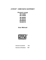
ATEUS ® - GSM DATA GATEWAY
Product range
501100E
501105E
501063E
501061E
504063E
504061E
User Manual
Version of manual:
10.0
Version of firmware:
2.47
Dear customer,
Let us congratulate you on purchasing our ATEUS ® - GSM DATA GATEWAY.
During the development and production of this product, care was taken to maximise
its value, quality and reliability. We hope you will use the GSM Gateway to it full
potential with long lasting benefits.
! Important !
•
•
•
The manufacturer currently updates the firmware integrated into this product. The ISP
technology (In System Programming) allows you to load the latest software versions via the
RS232 port on the unit from any computer. For the latest software version including all
accessories please refer to www.2n.cz, for instructions please see the “Control Software
Upgrade” section of this manual. We recommend you use the latest software version in
order to guarantee the latest functionality of this GSM Gateway.
To program your GSM Gateway parameters using a PC you need the “GSM – Program
Software“. For the most recent version of this programming tool please refer to www.2n.cz.
You will find the latest version of this Manual in the popular .PDF format on www.2n.cz also.
You are recommended to view the latest version in order to find explanations of new
functions necessary for any software updates.
•
Please read this Manual carefully before installing and using this product for the first time.
The manufacturer is not liable for any loss incurred by the user as a result of incorrect usage
of the unit. Our warranty terms and conditions do not cover damage caused by rough
handling, improper storage, or exceeding the specified technical parameters.
•
This Manual is quite comprehensive and includes sections that are not applicable for the
basic installation of the unit, other section also include information that may not be
applicable to your particular. Please note your gateway model number and refer to these
sections only.
•
Preliminary information on functions that will be available in later software releases will have
a light-grey background or in grey font.
1
History
Version What has changed or new in this version
•
•
•
•
•
•
7
•
•
•
•
•
8.6
•
•
•
•
•
•
•
9
9.1
9.2
9.3
10.0
•
•
•
•
•
•
•
•
•
•
•
•
•
•
Ordering numbers for dual-band models changed – see assortment preview
Assortment preview updated with 19” rack, battery cover and batteries
New parameter 110 – adjusting of echo cancellation
All applicable to 19” models 910121202E a 910121203E
Preview information for model 501100 (dual band)
New or updated parameters of model for PBX internal line (extension): 302,
318, 321, 322, 323, 324, 331, 341, 342, 353, 354
Individual help for all parameters for internal line interface added
Modified functional verification for model for PBX extension line
Comprehensive description of both incoming and outgoing calls for model for
PBX extension line, flowchart for incoming call added
On GSM Gateway for PBX extension line, intelligent incoming call routing was
extended. From version 2.30 of software it enables dialling of extension for
selected CLIPs.
Parameters “Take away” and “Append” in Call sorting table are enabled and
working in software version 2.32 and higher.
New chapter 6.5.: Remote programming by PC
Models for external line newly supports pulse dialing (parameter 201)
New function - Automatic Dialing, so-called "Baby-Call", parameters 156 and 157
New parameter 111 - Silence after dialing
Parameter 411 and 412 (Time for closing or opening of switch) functionality
Model 501053E was added to the assortment review. It is a passage type, identical
to 501100E.
Only dual-band models retains in this manual. Single-band 900 MHz models with
M20 were removed.
Model 501053 removed
Model 501105 added (GPRS version of 501100)
New parameter 115 - international prefix (usually 00)
New parameter 116 - country code (sooner parameter 6002)
New parameter 117 - long distance code (usually 0 or none)
New parameter 118 - operator prefix (reserved for future use)
Extended function of parameter 233 - end of call signal can reverse line polarity
also in on-hook state
New subchapter 6.3.6 – Erasing of parameters
Automatic data call answering option added
Function for switches "closing for pre-programmed time" established;
parameters 411 and 412, time 0.1 sec to ca. 40 min.
New parameters 158 and 159 - maximum time of call
Model for PBX extension line is now able to convert DTMF dialing to pulse, when
manual dialing for incoming call is enabled, but PBX receives pulse dialing only.
New parameter 166 – Information about voice calls can be sent out via serial
interface
New PCB issue – models 501100 and 501105
2
Checklist
Packaging list, please check the contents of your unit:
Item
Quantity
GSM Gateway - model corresponding to the order no.,
refer to the type label on the GSM Gateway backside
1
Mains (A.C. power supply) cord
1
Telephone line cord
1
Serial cable
1
Antenna
1
Holder (for fixing to the wall)
1
Rawlplugs
2
Screws
2
Fuse for battery
1
This manual
1
Warranty Certificate
1
Software on floppy or CD-ROM
1
Notes
1)
2)
3)
Notes:
1) Versions shipped without mains cord (order no. with different suffix) are available also.
2) Only for models with battery back up.
3) Software enclosed:
• GSM program
• SMS program
• Driver for PC
3
Contents
1. Introduction ............................................................................................6
1.1. PURPOSE ..........................................................................................................................6
1.2. HOW TO SAVE GSM CALL COSTS .......................................................................................6
1.3. OTHER ADVANTAGES AND APPLICATIONS .............................................................................6
1.4. PRODUCT OVERVIEW .........................................................................................................7
1.5. MAIN FEATURES ................................................................................................................7
2. Basic Installation Instructions ................................................................8
2.1. PROPER LOCATION ............................................................................................................8
2.2. TELEPHONE LINE CONNECTION ...........................................................................................9
2.3. EXTERNAL ANTENNA CONNECTION ....................................................................................11
2.4. SIM CARD SET-UP AND INSTALLATION ...............................................................................12
2.5. POWER SUPPLY CONNECTION...........................................................................................13
2.6. BACK-UP BATTERY CONNECTION ......................................................................................13
2.7. FUNCTIONAL VERIFICATION ...............................................................................................14
2.8. LED INDICATORS .............................................................................................................16
3. User Manual – Description of Basic (Voice) Function ............................ 18
3.1. OUTGOING CALLS - GSM GATEWAY ON PBX’S CO LINE.....................................................18
3.2. OUTGOING CALL – GSM GATEWAY ON PBX’S SUBSCRIBER LINE .......................................19
3.3. INCOMING CALL - GSM GATEWAY ON PBX’S CO LINE .......................................................21
3.4. INCOMING CALL - GSM GATEWAY ON PBX’S SUBSCRIBER LINE ..........................................22
3.5. MORE LOCAL CALLS DURING ONE GSM CONNECTION ..........................................................24
3.6. AUTOMATIC DIALING ("BABY CALL") ....................................................................................24
3.7. INTELLIGENT INCOMING CALL ROUTING ..............................................................................24
3.8. TELEPHONE LINE TONES, RINGING COURSE - SUMMARY ....................................................26
3.9. PIN/PUK CODE ENTERING...............................................................................................27
3.10. NOTES ............................................................................................................................28
3.11. INSTRUCTIONS FOR USE FOR COMMON USERS ...................................................................29
4. User Manual – Description of Data and SMS Functions ......................... 30
4.1. USAGE OF UNIVERSAL INPUTS...........................................................................................30
4.2. USAGE OF UNIVERSAL OUTPUTS .......................................................................................32
4.3. USE OF DATA MODE .........................................................................................................35
4.4. PC-BASED SMS RECEIVE/SEND ......................................................................................37
4.5. SECURITY CENTRE ...........................................................................................................37
5. Installation Instructions for Advanced Users ........................................ 38
5.1.
5.2.
5.3.
5.4.
5.5.
5.6.
5.7.
5.8.
DESCRIPTION FOR GSM GATEWAYS EXCLUDING 19'' RACK MOUNTED MODELS .....................38
DESCRIPTION FOR 19'' RACK MOUNTED MODELS .................................................................41
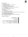
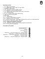
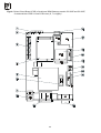
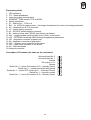
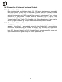
DESCRIPTION OF GSM GATEWAY PCB .............................................................................42
CONNECTION OF UNIVERSAL INPUTS AND OUTPUTS ............................................................54
BACK-UP BATTERY, REPLACEMENT ...................................................................................56
FUSE EXCHANGE .............................................................................................................57
LITHIUM BATTERY EXCHANGE ...........................................................................................58
MICROCOMPUTER EXCHANGE ...........................................................................................58
4
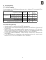
6. Programming ........................................................................................ 59
6.1. HOW TO PROGRAM ..........................................................................................................59
6.2. BEFORE PROGRAMMING ...................................................................................................59
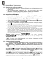
6.3. HANDSET-BASED PROGRAMMING ......................................................................................60
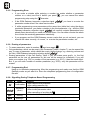
6.4. PC - BASED PROGRAMMING VIA SERIAL INTERFACE ............................................................63
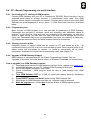
6.5. REMOTE PROGRAMMING BY PC ........................................................................................64
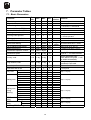
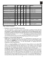
7. Parameter Tables .................................................................................. 70
7.1. BASIC PARAMETERS .........................................................................................................70
7.2. MODEL FOR PBX’S CO LINE - INTERFACE PARAMETERS .....................................................75
7.3. PBX SUBSCRIBER LINE (EXTENSION) MODEL - INTERFACE PARAMETERS .............................77
7.4. UNIVERSAL INPUT AND OUTPUT PARAMETERS ....................................................................81
7.5. CALL SORTING TABLE ......................................................................................................86
7.6. INTELLIGENT INCOMING CALL ROUTING TABLE....................................................................92
7.7. ACOUSTIC FAILURE SIGNALLING PARAMETERS ...................................................................93
7.8. OPERATION MONITORING PARAMETERS .............................................................................94
7.9. SERVICE PARAMETERS .....................................................................................................96
8. Miscellaneous ....................................................................................... 98
8.1. TELEPHONE COST SAVING TIPS ........................................................................................98
8.2. TROUBLE SHOOTING ........................................................................................................99
8.3. LIST OF ABBREVIATIONS ....................................................................................................99
9. Technical Parameters .......................................................................... 100
5
1. Introduction
1.1. Purpose
•
•
•
•
When connected to a PBX, the ATEUS ® - GSM DATA GATEWAY allows its users to make
direct calls via the GSM network. It can work with a telephone set, coin-operated automatic
machines, etc.
The voice mode, i.e. an outgoing or incoming call, is the basic function of the GSM Gateway.
The Gateway is equipped with all functions necessary for this purpose and offers ease of
use in this mode.
Moreover, the GSM Gateway provides (in connection with a PC) data mode and SMS
receive/send mode too. With SMS messages, universal inputs and outputs can be used
also. These additional functions increase the utility value of the product.
You need no additional equipment (mains adapter, external GSM telephone) to run the GSM
Gateway. The installation is so easy that even a non-professional can install it. All
programmable parameters are set at optimum values by default. Once you have connected
the telephone line, antenna, power supply and your SIM card, you can start making calls
without hesitation.
1.2. How to Save GSM Call Costs
•
•
•
•
•
By connecting a GSM Gateway to your PBX you can make direct calls into a mobile network.
This saves PSTN – GSM connection costs. Mobile telephone calls made by your colleagues
from outside to your headquarters will be cheaper too.
With the GSM Gateway you can use the most convenient tariff rate of your GSM operator,
because calls of all your GSM Gateway users will be billed together.
If you use an answering and recording machine – a GSM service, you may pay for retrieving
messages. If you connect an answering machine of your own to the GSM Gateway, you pay
nothing for the retrieval.
With the GSM Gateway you can eliminate selected numbers. You won’t pay for a call that is
disabled.
You can also get a listing of the time and length of selected calls to find easily why your bill is
higher than it should be.
1.3. Other Advantages and Applications
•
•
•
You can establish a telephone connection even where there are no fixed telephone lines
available (exhibitions, fairs, conferences, chalets...).
You are not exposed to the high-frequency electromagnetic field as with a mobile telephone.
You can also attach a coin-telephone to the GSM Gateway, as it is able to send tariff pulses.
You can assess the price for call connections yourself (with profit).
6
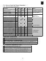
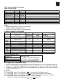
1.4. Product Overview
Model
Order No.
Older model for 1 PBX CO line (only for comparison)
501052E
For 1 PBX CO line, low-cost model (see separate manual)
501101E
For 1 PBX CO line, power supply w/o back-up
501100E
For 1 PBX CO line, power supply w/o back-up, GPRS !)
501105E
For 1 PBX CO line, power supply with back-up
501063E
For 1 PBX extension, power supply w/o back-up
501061E
For 1 PBX CO line, for 19" rack
504063E
For 1 PBX extension, for 19" rack
504061E
Rack 19" with bus and power supply unit (see below)
506000E
Battery set for 19“ models, 2x 6V / 10 Ah
506010E
Power supply, for 19“ models, w/ back- up, max. 12channels 910121220E
Battery pack with cover, for models with back-up, not for 19" 910121090E
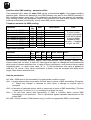
1.5. Main Features
•
•
•
•
•
•
•
•
•
•
•
•
•
•
•
•
•
•
•
•
•
•
•
•
•
•
•
DTMF dialling
Pulse dialling
Operates on PBX CO line
Operates with answering machine or telephone
Operates on PBX extension line
GSM module SIEMENS TC35 or MC35, 900 and 1800 MHz band
High quality voltage protection at line interface
No external mobile phone needed
An easy installation – Plug & Play
Battery operation during AC power failure
Barring possibility for selected calls
Intelligent end of dialling recognition – faster connection
Intelligent Incoming Call Routing
Service buffer – list of selected events and calls
Tariff pulse transmitter – e.g. for coin-phone
Begin & end of call signalling supported
Two binary inputs – transmits SMS, for watching whatever you need
Serial port RS-232C – for connecting to any PC
SMS messages can be received & transmitted by PC
Fax messages can be received & transmitted by PC
Data mode – can be used as a modem with any PC
GPRS data mode, 4+1, class B
Two universal outputs – for controlling whatever you need by SMS
Programming by phone
Programming by PC
Remote programming by PC
Acoustic failure signalisation
Explanatory Notes:
! Yes
*) Yes, but with limited capabilities
!) New model
7
! ! !
! ! !
!
!
!
!
! ! !
! ! !
! ! !
! ! !
! ! !
! ! !
! ! !
! ! !
! ! !
!
! ! !
! ! !
! ! !
! ! !
! ! !
! ! !
!
!
!
!
!
!
!
!
!
!
!
!
! !
!
! !
! !
!
!
!
!
!
!
!
!
!
!
!
!
!
!
!
!
!
!
!
!
!
!
!
!
!
!
!
!
!
!
!
!
!
!
!
!
!
!
!
! *)
!
!
!
!
!
!
!
!
!
!
!
!
!
!
!
!
!
!
!
!
!
!
!
!
!
!
!
!
!
!
!
!
!
!
!
!
!
!
!
!
!
!
!
!
! ! !
!
! !
2. Basic Installation Instructions
This chapter describes the basic connection of the GSM Gateway that can be made in a few
minutes. All you have to do is to connect an antenna, the power supply cable and telephone
line, insert your SIM card and the GSM Gateway is ready to work.
2.1. Proper Location
•
•
•
•
•
•
•
•
•
•
•
The ATEUS ® - GSM DATA GATEWAY is a transmitter in principle. You must comply with
the local regulations and laws in your country pertinent to usage of mobile phones and
transmitters!
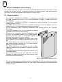
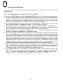
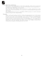
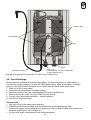
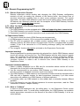
The ATEUS ® - GSM DATA GATEWAY is designed for vertical mounting. For the required
working position see Fig.1.
The GSM Gateway may be operated in a position other than vertical (on a desk, e.g.) for a
short time only – for quick maintenance testing, for example.
For the acceptable range of operating temperature and humidity refer to the “Technical
Parameters”.
The GSM Gateway may not be operated at places
exposed to direct solar or heat radiation.
Exceeding the acceptable operating temperature does
not have an immediate impact on the GSM Gateway
function, but may result in accelerated ageing (of
batteries in particular!) and lower reliability.
The GSM Gateway is designed for indoor use. It must
not be exposed to rain, water, condensed moisture, fog,
etc.
The GSM Gateway must not be exposed to corrosive
gas, fumes of acids or solvents, etc., or corrosive liquids,
during cover cleaning, for example.
The GSM Gateway is not intended for use in highvibration locations such as means of transport, machine
rooms, etc.
The GSM Gateway should be located with respect to the
GSM signal quality.
A free space should be left over and under the GSM
Gateway for cables and flowing air that removes heat
produced during the operation.
Fig. 1.: GSM Gateway Working Position
•
19" rack mounted models are destined only for corresponding 19" rack (see assortment preview).
Mount these GSM Gateways according to 19" rack manual. Rules listed above are mentioned for all
models, of course.
8
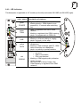
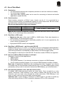
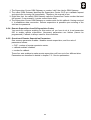
2.2. Telephone Line Connection
2.2.1. Connection to PBX - models for external line of PBX
Connect the ATEUS ® - GSM DATA GATEWAY to a free external (C.O.) line of your PBX
(the GSM Gateway models for external (C.O.) and local line (extension) are not
interchangeable!). With a CO line, define a different access number for this line than for the
remaining CO lines during the PBX programming. ATEUS ® PBXs made by 2N
TELEKOMUNIKACE a.s. are equipped with the Least Cost Routing (LCR) software, which
allows you to use the same access number for all CO lines.
Fig. 2.: Connection to PBX
C.O. line including callmaking example
Access
to
GSM
gateway,
connected this way (to external line
of PBX) must be provided by a
prefix, different to the prefix for C.O.
line access. Another solution is a
LCR (Least Cost Router) inside the
PBX - software that is able to
choose right direction for every call
automatically.
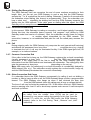
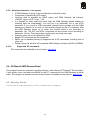
2.2.2. Connection to Telephone Set (Answering Machine, Coin-Operated Automatic
Machine) - models for external line of PBX
You can connect any telephone set or some other terminal equipment to the GSM
Gateway model for PBX external line module; see Fig. 3. For convenience, you can add
“ATEUS ® - Ping pong ” (intelligent double or triple branch made by 2N
TELEKOMUNIKACE a.s., order Nos. 831127, 831128, 831137, 831138) to interconnect
several devices, such as a coin-operated automatic machine, another telephone set, and
an answering machine.
Note: If you connect a coin-operated phone, be sure to program the transmission of tariff
pulses and pseudo tariff metering properly as well as to bar calls with unpredictable tariff
rates!
Fig. 3.: Optional
Connection of More
Terminal Equipment
9
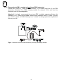
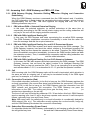
2.2.3. Connection to PBX - models for local line of PBX (extension)
Connect the ATEUS ® - GSM DATA GATEWAY to an unused local line of your PBX
(extension). Attention! The GSM Gateway models for external (C.O.) and local line
(extension) are not interchangeable!
Attention! It is highly recommended to set your PBX to disable outgoing calls from this
extension to C.O. lines, and to disable access to this extension from C.O. lines. This way
you avoid an abuse of GSM Gateway from "outside" (making expensive long-distance
calls on your bill).
Fig. 4.: Connection to PBX local line (extension) including call-making example
10
2.3. External Antenna Connection
Connect an antenna or an external antenna cable into the FME connector. The antenna
location should have a good GSM signal. The antenna should be in the vertical position. For
antenna and cable parameters refer to the “Technical Parameters”. Tighten an antenna
connector gently by hand; do not use any tools!
11
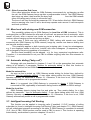
2.4. SIM Card Set-up and Installation
2.4.1. Operator / SIM Card Selection
To perform this GSM Gateway function you need a SIM card of a GSM network operator,
using the 900 MHz or 1800 MHz band (depending on GSM Gateway model). The
ATEUS ® - GSM DATA GATEWAY works with 3V SIM cards. All SIM cards except for the
oldest ones meet this condition. If you are not sure, ask your GSM operator about voltage
of your old SIM card. If your SIM card is new or you are going to buy a new one, you
need not worry – your SIM card will be O.K.
2.4.2. PIN Entering Blocking (Optionally)
The GSM Gateway provides automatic PIN entering by default. You can disable PIN
entering on your SIM card (using a mobile telephone into which you insert your SIM card
for this purpose). If you do disable, you need not worry as to whether there is a PIN code
stored in your GSM Gateway memory. If you enable PIN entering, your GSM Gateway
will require a PIN code after the first power-on and if you enter the PIN correctly, the
GSM Gateway will store it in its memory and enter automatically in the future.
2.4.3. GSM Network Service Setting (Answering Machine, Call Forwarding)
Before the SIM card installation decide whether you will use the incoming call
forwarding service provided by GSM networks (call forwarding in the event of busy line,
absence, unavailability...). However, it is more convenient to disable all call forwarding
modes (the GSM operator’s answering machine, e.g.) and use an answering and
recording machine of your own. If you have more GSM Gateways with your PBX, you
can forward calls when one GSM Gateway is busy, etc.
2.4.4. Roaming Parameters Setting (Calling via Foreign GSM Networks)
The GSM Gateway disables roaming by default. It is usually convenient because most
people do not travel with the GSM Gateway and there is a risk with roaming in foreign
countries that, due to a failure in the local GSM network, you might get registered in
another network and pay much more for your calls. To enable roaming and set network
preferences, complete the list of GSM networks to be preferred using your mobile
telephone and then enable roaming while programming the GSM Gateway.
The registration of the GSM Gateway in a foreign GSM network is signalled by a special dial
(refer to the list of tones) and you have to dial numbers including international
tone
prefixes that can be easily barred (refer to Programming, Call Sorting Table).
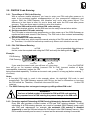
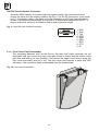
2.4.5. SIM Card Insertion in GSM Gateway
Some models have a cover without hole for SIM exchange. In this case, release the two
screws and remove the upper cover face (see Fig. 6). To install the SIM card press the
yellow button on the SIM holder using a suitable tool (e.g. scissor) to make the drawer
slide out. Remove the drawer, insert the SIM card in it, slide the drawer back and click
into position. Then replace the cover face and tighten the screws, if removed. This
protects the GSM Gateway circuits against dust and damage!
Attention! If SIM memory is full and a further SMS is received, the
oldest one will be erased in order to unblock the path for switch
control commands. If switches are not used, erasing can be disabled
by parameter 109, see chapter 7.1.
12
2.5. Power Supply Connection
2.5.1. For all GSM Gateways excluding 19'' rack mounted models
• Make sure that the voltage in your mains corresponds with the data on the product label.
• Make sure that the antenna has been connected. If you connect a power supply to the
equipment without the antenna, you might cause damage to the GSM module transmitter.
• Connect your power cord. After a while, the green indicator “AC Supply O.K.” should go on.
2.5.2. For 19'' rack mounted models
• These GSM Gateways can be handled (inserted into rack or removed) "alive" - without
switching power unit off.
After switching power on (or after hot insertion), the upper green LED lamp with power
•
icon must light up after a moment.
Use common power unit in accordance with 19" rack manual.
•
2.6. Back-Up Battery Connection
This paragraph applies to models 501061E and 501063E, i.e. backed-up models excluding 19"
rack mounted models.
For these models, a back-up battery with cover can be ordered - ordering No. 910121090 (E). This
is a maintenance-free lead battery pack 12V / 1,2Ah with metallic cover, whose design matches the
GSM Gateway. This cover includes the accessories for wall mounting.
Battery installation
While placing the battery pack, avoid exposing it to high temperature if not necessary and
mount it to the wall, if possible. Mounting method, holder etc. is the same, as for GSM Gateway.
Plug a cable into a fitting connector on GSM Gateway. Check a fuse in holder and insert it, if the
holder is empty. Switch on.
Notes:
• Circuits in GSM Gateway are designed to handle 12V / 1,2Ah maintenance-free lead battery.
Also a different lead battery with a nominal voltage 12V and a capacity of 1 to 2Ah or a set of 10
NiCd or NiMH cells of the capacity from 600 to 1,600mAh can be used too. Of course, a
manufacturer cannot guarantee a proper charging, if the battery parameters are too different.
Especially, a battery of a higher capacity may not reach an end-of-charge voltage. It may cause
a permanent charging, and it may damage the battery! Such battery must be charged externally.
In this case, the charging function has to be disabled by software – see chapter 7.1, parameter
170. An external 12V power can be applied too.
• The accumulator is charged and checked automatically, and the GSM Gateway indicates the
charging and emergency statuses (disconnected, short-circuit, or fully discharged battery) and
stores these events in the service buffer. If lamp "charge" is dark (strictly speaking, it flashes
shortly with a long period, done by conservation charging), the accumulator is fully charged.
End of charging, discharging and all failures, such as disconnected accumulator or short
circuit, are stored in service buffer.
• See chapter 5.5 for details, as well as for standard battery replacement.
• Battery backup for rack mounted 19" models is provided by common (one for rack)
accumulator, see assortment preview. This accumulator is charged and checked automatically
as well. Moreover, 19" supply unit is monitoring a battery operation and signalizing its
remaining charge and need for replacement (by watching over decrease of capacity).
13
2.7. Functional verification
Recommendation: check GSM Gateway functionality prior to connecting it to your PBX and
programming.
2.7.1. For GSM Gateways for external (C.O.) line of PBX
If you have a GSM Gateway model for external (C.O.) lines on a PBX, follow these instructions:
1. Connect GSM Gateway to previously checked telephone set. Verify that this telephone is
switched to DTMF and its ringer is ON. If is better to check a SIM card too, using a mobile
phone. It is not necessary to fix GSM Gateway to a wall for testing – it can lie on flat surface
as well. Excepting this, follow chapters 2.2 to 2.5 to connect all needed.
2. If the inserted SIM card requires a PIN, the red lamp “Enter PIN” will light up. In this case,
pick up the handset of connected a phone. You will hear a PIN tone
.
Enter PIN as described in chapter 3.9.2 and hang up, the red “Enter PIN” lamp will go out.
3. The GSM Gateway will register itself into the GSM network. First, the red “No GSM network”
lamp must go out. After a moment, the green “GSM ready” lamp will light up.
4. Pick up the phone; you will hear the dialling tone
and the “Line ready” lamp will start
blinking. If it doesn’t, the phone or its connection is bad.
5. Now check for signal quality. Enter programming mode according to chapter 6.3.2, skipping step
No. 1 (this applies only in the case of connection to a PBX). Indication of GSM signal quality will
be turned on automatically. As more lamps are lit, signal quality is better. If at least one green
lamp is lit up, signal quality is excellent. Try to find a good place for the antenna. Keep the
antenna vertical and move it slowly – signal quality information is updated every three seconds.
Remember that a movement as small as 10 cm may have a considerable effect on signal
quality, as well as a position close to your body. The best way is to step aside after each
relocating of antenna. Hang up after positioning the antenna; do not program anything!
6. Make an outgoing call. Call your colleagues mobile e.g. and verify that you hear each other
well. In the case of a completely new pre-paid SIM card, one outgoing call is necessary for
SIM card activation. Until it is activated an incoming call cannot be received! Make an
incoming call now. Call the GSM Gateway; the phone should ring.
7. The GSM Gateway is now checked. You can now connect it to a vacant C.O. line in the
PBX. After connection is completed, check both incoming and outgoing calls again. This
may, of course, necessitate some programming or settings changes of the PBX. If
everything is O.K., you can go to programming, if it is required - see chapter 6.
14
2.7.2. For GSM Gateways for local line (extension) of PBX
If you have a GSM Gateway model for a local line (extension) in the PBX, follow these
instructions:
1. Use an unused, previously checked local line of PBX. Special lines, such as lines for socalled "key phones", or ISDN lines cannot be used! It is recommended that the PBX will give
or permanent tone after call finishing (after hooking up on one side,
a busy
the other side is advised by this tone).
2. Use a previously checked telephone handset, switched to DTMF and connected to another
extension of the PBX. It is best to use a cordless phone; this allows you to closely observe
the lamps on the GSM Gateway.
3. Disconnect the phone, which was previously used to check the unused line. Using the same
cable connect the GSM Gateway. It is recommended that you check the SIM card too, using
a mobile phone. Again it is not necessary to fix the GSM Gateway to the wall for testing – it
may be placed on a flat surface if necessary. After this, follow chapters 2.2 to 2.5 to make all
required connections.
4. If inserted SIM card requires a PIN, red “Enter PIN” lamp will light up. On models without this
separate lamp, common "error" lamp will light up. In this case, pick up the phone connected
to another extension (e.g. cordless phone) and call GSM Gateway extension. You will hear a
. Enter pin as described in chapter 3.9.2 and hang up. Red
PIN tone
“Enter PIN” lamp will go out.
5. The GSM Gateway will register itself into the GSM network. First, red “No GSM network”
lamp must go out (if present). After few seconds the green “GSM ready” lamp will light up
(this lamp is on every model).
6. Pick up the phone connected to another extension (e.g. cordless phone) and call GSM
Gateway extension; you will hear dialling
tone and green lamp “Line ready” will start
blinking. If not, and you hear ringing only, the phone or its connection is bad or you called an
invalid extension number.
7. Now check signal quality. Enter programming mode according to chapter 6.3.2. Indication of
GSM signal quality will be turned on automatically. As more lamps light up, signal quality is
better. If at least one green lamp is lit, signal quality is excellent. Try to find a good place for
antenna. Keep the antenna vertical and move it slowly – signal quality information is updated
every three seconds. Remember that a movement as small as 10 cm may have a
considerable effect to signal quality, as well as a position close to your body. The best way is
to step aside after each relocating of the antenna. Next, if PBX doesn't support DTMF
dialing, set parameter 311 - type of dialing, to pulse dialing. To check an incoming call
program parameter 114; switchboard operator number, i.e. extension to be called.
Programming can be done by phone - see chapter 6.3 , or by PC.
8. Hang up after placing antenna; do not program anything!
9. Make an outgoing call. Call your colleagues mobile e.g. through the GSM Gateway and
ensure that you hear well each other. In the case of a completely new pre-paid SIM card,
one outgoing call is necessary for SIM card activation. Until the SIM is activated, an
incoming call cannot be made! Check an incoming call now. Call the GSM Gateway. If PBX
doesn't support DTMF dialing, line selected by parameter 114 will be ringing. Otherwise, you
will hear the dialing tone of your PBX. Dial the number of an extension; the phone will ring.
10. The GSM Gateway is now checked. If necessary you can go to programming now - see
chapter 6.
15
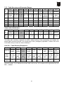
2.8. LED Indicators
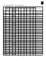
2.8.1. Table – Basic LED Functions for models 5010xxE
Colour
Comments
Green
Lights, when GSM module is powered
Yellow
Charging - goes out when battery is fully charged
Yellow
Battery powered (during AC failure)
Red
Short circuit, low or disconnected battery
Green
Logged on, blinking within roaming
Green
Line is on-hook, it is blinking after pick up
Green
Lights during established call
Blinking during dialling and ringing
Yellow
Yellow
Lights during established data connection, blinking
during establishing of data connection and ringing
Blinking if 1 or more SMSs are in buffer. Lights if SIM
memory is full (10 - 40 SMSs, depending on SMS type)
Red
SIM card removed
Red
PIN is not entered
Red
Line pow ered down (it is checked
again each minute to recover to normal
operation)
Red
Lights when GSM module is not logged-on
It is blinking during indication of GSM signal level
Note: Three LED's destined for battery status indication (Battery charge, Battery supply,
Battery low) are unused in models without battery backup.
2.8.2. Signal Intensity Indication
On models 501061E and 501063E the bottom group of nine LEDs is used for indicating
the GSM signal level. On other models, there are 5 LEDs available but indication works
analogically. Using the “GSM Signal Level Indication” (refer to Programming, Basic
Parameters) you enable the indicating mode where the GSM Gateway displays the signal
intensity for 2 seconds every 10 seconds. In the meantime, the LED's indicate all
statuses normally.
When the GSM Gateway is in the programming mode, the LEDs indicate the signal
intensity continuously and the information is updated every three seconds. This mode is
suitable for searching for the ideal antenna position during installation.
16
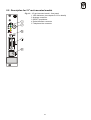
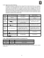
2.8.3. LED indicators
This description is applicable to 19” models (on the left) and models 501100E and 501105E (right).
color, name
green
POWER
green
GSM
yellow
LINE
yellow
DATA
Description of statuses
•
•
•
•
•
•
•
•
•
•
•
•
red
ERROR
•
•
lights = GSM module is powered
blinking slowly = GSM module is not
powered (c. 6 seconds after switching
on)
lights = registered into native GSM
network
blinking = registered into GSM, roaming
dark = not registered into GSM sítě
lights = call
blinking = off-hook, dialing or ringing
dark = on-hook, or line error
lights = GSM data connection
established
blinking = data exchange with PC, GSM
data connection not established
dark = no activity on serial interface
lights = at least one from these errors:
o line error
o SIM is not present
o PIN is not entered
blinking = GSM signal quality indication
dark = no error
(ATTENTION! It doesn’t imply, that
GSM Gateway is registered into GSM
network!
17
3. User Manual – Description of Basic (Voice) Function
Users mostly use their PBXs and GSM Gateways intuitively, without reading any
instructions, or follow very simple instructions provided by an authorized person. The following
functional description is therefore intended for technicians, who follow the instructions
(depending on the PBX set-up) and solve any operational problems.
3.1. Outgoing Calls - GSM Gateway on PBX’s CO line
3.1.1. Picking Up the Line
The PBX picks up a line the moment a subscriber picks up his or her handset and dials a
number that is interpreted by the PBX as the “GSM Gateway Access“ code. This code
depends on the PBX type and set-up. Some PBXs accept the GSM prefix as this code.
Then, the user need have no worry that the call is made via the GSM Gateway.
Note: If the GSM Gateway is busy, the PBX can either give the caller the busy tone
or choose another connection (PSTN, or there may be more GSM
Gateways with one PBX).
3.1.2. GSM Gateway Ready Signalling
The GSM Gateway registers the off-hook (current inflow) immediately and then, if
everything is O.K., starts sending its usual dialling tone
. Now the subscriber can
dial the number.
Notes:
• As far as pulse dialing is selected, DTMF dialing can be used to enter programming
mode and program GSM Gateway by phone. In case of any other DTMF dialing, GSM
Gateway will answer by bysy tone.
• If there is no GSM signal, no SIM card has been inserted, no PIN code has been
entered, or if there is another problem, the PBX transmits a special tone (see below –
“Telephone Line Tones“).
3.1.3. Dialling Receive
The GSM Gateway is ready to receive pulse or tone dialling (according to the set-up). As
soon as the subscriber starts dialling a number, the GSM Gateway mutes the dialling
(as with public telephone exchanges). The user must dial digits in no more
tone
than 6 second intervals; otherwise the number is regarded as complete and sent to the
GSM network (this timeout is programmable).
Notes:
• If pulse dialing is selected, DMF can be still used for programming and switch control.
• Some PBXs analyse the whole number first and then transmit the dialling into the CO line
(GSM Gateway). Here, the signalling type and the timeout depend on the PBX set-up!
3.1.4. Dialling End Recognition
The GSM Gateway itself can recognize the end of some numbers according to their
length. Moreover, you can set your GSM Gateway in such a way that the GSM Gateway
accepts the ‘*‘ or ‘#‘ (for tone dialling only) symbols as the end of dialling. Otherwise, it
waits 6 seconds after the subscriber stops dialling (the timeout is programmable). Then,
the subscriber can hear a short tone signalling the dialling end and the GSM Gateway
transmits the received number into the GSM network. If the caller goes on dialling, the
GSM Gateway will not accept the extra digits!
3.1.5. Connection Establishing
In this moment, GSM Gateway is making a connection, and it takes typically 8 seconds.
During this time, the subscriber hears a special "call progress" tone (differs by GSM
18
Gateway model and version of software). Next, the subscriber usually hears the ringing
tone
or another signal transmitted by the GSM network.
The connection, however, is not established and paid for until the called party answers
the phone. The GSM network signals this moment and the GSM Gateway can pass the
information to the PBX. If this type of signalling is used (exceptionally), the calling party
can hear a click in the earphone.
3.1.6. Call
During outgoing calls, the GSM Gateway can compute the cost (pseudo tariff metering)
and it can send tariff pulses. A call may be terminated forcibly if the GSM signal gets lost,
for example, or in similar situations.
3.1.7. Connection Termination (End)
If the caller is the first to hang up, the GSM Gateway registers the on-hook immediately
(the current flow stops) and terminates the connection. If the called party is the first to
hang up, the GSM Gateway gets the information from the GSM network and terminates
the connection. The GSM Gateway can pass the information to the PBX. The calling
party gets the busy tone
(or another type depending on the set-up).
The time of call may be limited by parameter 158. 30 sec before this limit, GSM Gateway
sends a warning tone. Last 10 sec a short beep repeats each second. A call interruption
follows, optionally busy tone and Power Down.
Note: With some calls, the called party‘s on-hook information is considerably delayed by
GSM network (30s, e.g.). The subscriber usually registers the on-hook earlier, hangs up,
and the GSM Gateway terminates the connection immediately.
3.1.8. Subscriber’s Disconnection (Power Down)
If a subscriber blocks the GSM Gateway by seizing the line without dialling a number, or
first and
fails to hang up after the call, he or she will get the busy tone
then is disconnected (Power Down status).
3.2. Outgoing Call – GSM Gateway on PBX’s Subscriber Line
3.2.1. GSM Gateway Ringing
The subscriber picks up the line and dials the extension number of GSM Gateway. The
PBX starts ringing this extension; the GSM Gateway registers this and picks up the line
after a programmed time.
Note: If the GSM Gateway is busy, the PBX can either give the caller the busy tone
or start ringing another extension (there may be more GSM Gateways
than one with one PBX).
3.2.2. GSM Gateway Ready Signalling
After picking up the line, the GSM Gateway starts sending the usual dialling tone
(if everything is O.K.). Then the subscriber can dial the number.
Note: If there is no signal, no SIM card has been inserted, no PIN code has been
entered, or there is another problem, the GSM Gateway transmits a special tone (see
below – “Telephone Line Tones“).
3.2.3. Dialling Receive
The GSM Gateway is ready to receive tone dialling. As soon as the subscriber starts
dialling a number, the GSM Gateway stops sending the dialling tone
(as with
public telephone exchanges). The subscriber must dial digits in no more than 6 second
intervals; otherwise the number is regarded as complete and sent to the GSM network
(the timeout is programmable).
19
3.2.4. Dialling End Recognition
The GSM Gateway itself can recognize the end of some numbers according to their
length. Also, you can set your GSM Gateway in such a way that the GSM Gateway
accepts the ‘*‘ or ‘#‘ symbols as the end of dialling. Otherwise, it waits for 6 seconds after
the subscriber stops dialling (the timeout is programmable). Then, the subscriber can
signalling the dialling end and the GSM Gateway transmits the
hear a short tone.
dialling into the GSM network. If the caller goes on dialling after this signal, the GSM
Gateway will not accept the excessive digits!
3.2.5. Connection Establishing
In this moment, GSM Gateway is making a connection, and it takes typically 8 seconds.
During this time, the subscriber hears a special "call progress" tone (differs by GSM
Gateway model and version of software). Next, the subscriber usually hears the ringing
tone
or another signal transmitted by the GSM network. The
connection, however, is not established and paid for until the called party answers the
phone.
3.2.6. Call
During outgoing calls, the GSM Gateway only computes the cost (pseudo-tariff metering)
and detects the permanent tone, busy tone
or another tone (e.g. ringing)
to terminate the call. A call may be terminated forcibly if the GSM signal gets lost, for
example, or in similar situations.
3.2.7. Common Connection End
If the caller is the first to hang up, the GSM Gateway registers the on-hook immediately
from the PBX) and terminates the
(usually permanent or busy tone
connection. If the called party is the first to hang up, the GSM Gateway gets the
information from the GSM network and terminates the connection. The calling party then
gets the permanent or busy tone
(depending on the set-up).
Note: With some calls, the called party‘s on-hook information is considerably delayed by
GSM network (30s, e.g.). The subscriber usually registers the on-hook earlier, hangs up,
and the GSM Gateway terminates the connection immediately.
3.2.8. Other Connection End Cases
If a subscriber blocks the GSM Gateway unnecessarily by calling it and not dialling a
number, or fails to hang up after a call, the GSM Gateway hangs up after a programmable
timeout. The GSM Gateway also hangs up when it has received the busy tone
from the GSM network (when the calling party is busy or refuses the call).
The time of call may be limited by parameter 158. 30 sec before this limit, GSM Gateway
sends a warning tone. Last 10 sec a short beep repeats each second. A call interruption
and hook up follows.
Caution! The GSM Gateway on a extension line of the PBX can
be called “from the outside“ (from PSTN) can be used (or
misused) by any person calling successfully to this line “from the
outside“! To avoid this, set the PBX and/or the GSM Gateway
properly (refer to the Call Sorting Table, „Remove“ and „Add“
selections).
20
3.3. Incoming Call - GSM Gateway on PBX’s CO Line
3.3.1. GSM Gateway Ringing, Extension Dialling, Extension Ringing and Connection
Establishing
When the GSM Gateway receives a command from the GSM network and, if available,
the CLIP information, it starts ringing (i.e. generating the ringing voltage – whose timing is
programmable) into the PBX. The PBX registers the ringing and then, one of the
following situations may occur:
3.3.1.1
PBX without DISA = Selected Extension Ringing
In this case, the selected extension (or several extensions at the same time or
sequentially according to the PBX set-up) starts ringing and the calling subscriber will
not pay for the call until the ringing extension answers.
3.3.1.2
PBX with DISA, Intelligent Routing Off
In this case, the PBX answers and starts reproducing the so-called DISA message.
The GSM Gateway establishes connection immediately in order that the caller can
hear the message and dial the required extension.
3.3.1.3
PBX with DISA, Intelligent Routing On, and CLIP Present and Known
In this case, the PBX also answers and starts reproducing the DISA message. The
GSM Gateway, however, has found the caller’s number in its Intelligent Incoming Call
Routing Table and thus knows the extension to be called. Therefore, the GSM Gateway
does not establish connection immediately, but serves the DISA function (waits and dials
the extension number). Then, it establishes the connection and the calling subscriber can
hear the ringing tone
and the called subscriber.
3.3.1.4
PBX with DISA, Intelligent Routing On, but CLIP Absent or Unknown
In this case, the PBX also answers and starts reproducing the DISA message. The GSM
Gateway, however, has not found the caller’s number in its Intelligent Incoming Call
Routing Table (or has not received the CLIP). Then it can (according to its set-up) either
work as described in 3.3.1.2, or as described in 3.3.1.3, plus dial the operator’s number.
3.3.2. Call
With incoming calls, the GSM Gateway waits until the call is terminated, which situation is
the same as with an outgoing call. A call may be terminated forcibly if the GSM signal
gets lost, for example, or in similar situations.
3.3.3. Connection Termination (End)
If the called subscriber (extension) is the first to hang up, the GSM Gateway registers the
on-hook immediately (the current flow stops) and terminates the connection. If the calling
party (PSTN) is the first to hang up, the GSM Gateway gets the information from the
GSM network and terminates the connection. The GSM Gateway can pass the
information on the PBX. The calling party then gets the busy tone
(or
another tone depending on the set-up).
The time of call may be limited by parameter 159. 30 sec before this limit, GSM Gateway
sends a warning tone. Last 10 sec a short beep repeats each second. A call interruption
follows, optionally busy tone and Power Down.
Note: With some calls, the called party‘s on-hook information is considerably delayed by
GSM network (30s, e.g.). The subscriber usually registers the on-hook earlier, hangs up,
and the GSM Gateway terminates the connection immediately.
3.3.4. Subscriber Disconnection (Power Down)
If a subscriber blocks the GSM Gateway unnecessarily by not hanging up after the call, he or
she will get the busy tone
first and then is disconnected (Power Down status).
21
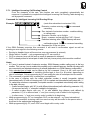
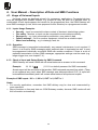
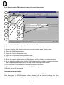
3.4. Incoming Call - GSM Gateway on PBX’s Subscriber Line
As this procedure is most sophisticated and it may be difficult to understand it, it is described
by two forms: flowchart and text. Please, choose a form, which you are more familiar with.
Fig. 5: Flowchart for Incoming Call - GSM Gateway
on PBX’s Subscriber Line
22
3.4.1. GSM Gateway Ringing
When the GSM Gateway receives a command from the GSM network and the CLIP
information, if available, it picks up a subscriber line of the PBX. Then, one of the
following two situations may occur:
3.4.1.1
Extension Dialling - Intelligent Routing On, and CLIP Present and Known
The GSM Gateway has found the caller’s number in its Intelligent Incoming Call
Routing Table and knows the extension to be called. Hence, it dials the extension
number.
Exception: If 0 (zero) is found in Intelligent Incoming Call Routing Table instead of
extension number, GSM Gateway skips dialing, and calling party hears a dialing tone
from PBX and dials number of required extension by DTMF. PBX usually receives
DTMF. If PBX receives pulse dialing only (and pulse dialing is selected by parameter
311), GSM Gateway starts to receive DTMF and converts it to pulse dialing (up to 16
digits).
3.4.1.2
Extension Dialling - Intelligent Routing Off, CLIP Absent or Unknown
The GSM Gateway has not found the caller’s number in its Intelligent Incoming Call
Routing Table (or has not received the CLIP, or Intelligent Routing is off). If a
parameter 310, "enable dialing for incoming call" is enabled, GSM Gateway only picks
up a line, such that a calling party hears a dialing tone of PBX and dials an extension
number by himself, in DTMF. PBX usually receives DTMF. If PBX receives pulse
dialing only (and pulse dialing is selected by parameter 311), GSM Gateway starts to
receive DTMF and converts it to pulse dialing (up to 16 digits). If a parameter 310,
"enable dialing for incoming call" is NOT enabled, GSM Gateway dials the pre-set
number, the operator’s number, e.g.
3.4.2. Extension Ringing, Connection Establishing
If calling party dials an extension, the GSM Gateway establishes connection immediately,
without waiting for any "connect" handshaking from PBX (if used or not). If GSM Gateway
dials an extension (to switchboard operator, or by I2CR table), then it establishes
connection just after dialling extension number (above), or wait for "connect"
handshaking from PBX (if used; in this case PBX must send it, otherwise call cannot be
either from
connected!). The calling party can hear the ringing tone
PBX, or from GSM network - it depends on this setting.
3.4.3. Call
With incoming calls, the GSM Gateway only detects the permanent tone, busy tone
or another tone (e.g. ringing), i.e. waits until the call is terminated, which
situation is the same as with an outgoing call. A call may be terminated forcibly if the
GSM signal gets lost, for example, or in similar situations.
3.4.4. Common Connection Termination (End)
If the called subscriber (extension) is the first to hang up, the GSM Gateway registers the
on-hook immediately (usually the permanent or busy tone.
from the PBX)
and hangs up. If the calling party (PSTN) is the first to hang up, the GSM Gateway gets
the information from the GSM network and hangs up. The calling party then gets the
busy tone
(or another tone depending on the set-up).
Note: With some calls, the called party‘s on-hook information is considerably delayed by
GSM network (30s, e.g.). The subscriber usually registers the on-hook earlier, hangs up,
and the GSM Gateway terminates the connection immediately.
23
3.4.5. Other Connection End Cases
If the called subscriber blocks the GSM Gateway unnecessarily by not hanging up after
the call, the GSM Gateway hangs up after a programmable timeout. The GSM Gateway
also hangs up when it has received the busy tone
from the GSM network
(when the calling party is busy or refuses the call).
The time of call may be limited by parameter 159. 30 sec before this limit, GSM Gateway
sends a warning tone. Last 10 sec a short beep repeats each second. A call interruption
and hook up follows.
3.5. More local calls during one GSM connection
This possibility relates only to GSM Gateway for local line of PBX (extension). This is
contingent also on PBX's behaviour after end of local call: we assume that an extension, which
remain off-hook, after a second one hooks up, hears a dialing tone and can dial another
number, without hanging up line and picking up again.
In this case, if local user (any extension of PBX), talking with remote user (mobile,
connected with GSM Gateway by GSM network) hangs up, remote user hears a dialing tone
and can dial another number.
This possibility applies to both incoming and outgoing calls. It may be advantageous,
e.g. if one employee needs to talk from "outside" with more colleagues (in sequence), and a
call is charged by flat price (regardless of its duration).
But the same possibility can be abused - e.g. for long, expensive long-distance calls.
Therefore, it is recommended to set your PBX to disable outgoing calls from this extension to
C.O. lines.
3.6. Automatic dialing ("baby call")
Outgoing calls are described in chapters 3.1 and 3.2 on the assumption that automatic
dialing is off (default). If parameter "Number for automatic dialing" is filled, this function is
automatically switched on and GSM Gateway operates as follows:
Model for external line:
As soon as line is picked up, GSM Gateway awaits dialing for limited time, defined by
parameter "time for automatic dialing". If user starts dialing within this time, GSM Gateway
operates normally, as described in chapter 3.1. Otherwise, if this time is out, GSM Gateway
automatically makes a call to programmed number.
Note: It is assumed, that GSM Gateway is connected to phone. If GSM Gateway is
connected to PBX, applicability of automatic dialing function depends on PBX's settings.
Model for local line:
GSM Gateway detects ringing from line and picks up. Then awaits dialing, for a time
defined by parameter " time for automatic dialing". If user starts dialing within this time, GSM
Gateway operates normally, as described in chapter 3.2. Otherwise, if this time is out, GSM
Gateway automatically makes a call to programmed number.
3.7. Intelligent Incoming Call Routing
This function can be applied to incoming calls (if enabled). If CLIP (number of calling
subscriber) is found in Intelligent Incoming Call Routing Table (see chapter 7.6.), GSM Gateway
will call a dedicated extension according to this table. If GSM Gateway is connected to external
(C.O.) line of PBX, DISA function must be used in PBX to serve it. This function is operating
automatically, as described in previous chapters 3.3 and 3.4.
24
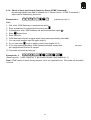
3.7.1. Intelligent Incoming Call Routing Control
From the viewpoint of the user, this function can work completely automatically but
moreover it is possible to complete the Intelligent Incoming Call Routing Table during any
call by special command:
Command for Intelligent Incoming Call Routing fill-up:
Example:
(route this subscriber to extension 234)
Extension number entering, or
for command
cancelling.
Zero instead of extension number - enables dialing
to calling party
Extension number, up to 8 digits
Empty - erases a record with this CLIP, if found.
Password entering, after it GSM Gateway will send
confirmation signal. Or
for command cancelling.
Password for fill-up into table
If the GSM Gateway executes this command, it will send a confirmation signal as well as
sending an error signal in the following events:
•
•
•
•
Routing is disabled (error will be sent as soon as password is entered).
Whole table is “locked” – only programming by PC can modify it.
CLIP is unknown (error will be sent as soon as password is entered).
CLIP is already stored in locked part of table; this entry has a priority and cannot be modified.
Notes:
• If 0 (zero) is entered instead of extension number, GSM Gateway enables calling party to dial any
number. This is a way, how to enable this possibility only to selected persons. Another incoming calls
are connected to pre-selected extensions or refused (dependent on a GSM Gateway configuration).
• Only unlocked part of table can be filled-up by this command. Once it is full, new ones will
overwrite oldest entries. Size of available unlocked part is from 0 to 99 entries, depending on
size of locked part. Only programming by PC can modify the size of locked part and its content.
• This command is ignored until a connection is established.
• In the case of outgoing calls, the called subscriber number is usually incomplete (without
international prefix). In case of incoming call, CLIP is complete and international prefix starts with “+”.
To make these numbers comparable, incomplete number is completed automatically within writing
to the table, this way:
o If called number begins with “00” (or with different international prefix defined by parameter 115),
it is removed and only “+” character is added to its beginning.
o If called number begins with one “0” (or with different long distance code defined by
parameter 117), it is removed and “+” and your country code is added to its beginning.
o In other cases, “+” and your country code is added to its beginning.
• While programming by PC, an incomplete CLIP can be entered – e.g. bare international
prefix. In this example, incoming calls from each country will be routed to the person who is
proficient in the appropriate language etc.
• While programming by PC, each CLIP must begin with country code.
25
3.8. Telephone Line Tones, Ringing Course - Summary
The ATEUS ® - GSM DATA GATEWAY transmits tones to the telephone line that signal its
operating status. The frequency is 425 Hz for all tones.
Common Dial tone:
• The equipment is registered in the domestic GSM network.
• The equipment is ready to receive dialling.
• This tone has the same parameters as the PSTN dial tone.
• The parameters of this tone are programmable.
Special Dial tone:
• The equipment is registered in a foreign GSM network – ROAMING.
• The equipment is ready to receive dialling.
• The parameters of this tone are programmable.
Ringing Tone:
• The called subscriber is free and his or her telephone is ringing.
• The GSM network transmits this tone; its parameters are beyond the control of the GSM
Gateway.
Busy Tone:
• This tone is transmitted if:
"# The SIM card has not been installed.
"# The GSM Gateway is not registered in the GSM network.
"# The equipment is registered in a foreign network, but roaming is disabled.
"# The called number has too many digits (over 30).
"# The called subscriber is busy.
"# The called number is bared by call sorting table.
"# The connection has been terminated.
"# GSM Gateway is in data mode.
"# There is a communication error between the control processor and the GSM
module, and a servicing intervention is required.
• This tone has the same parameters as the PSTN busy tone.
• The parameters of this tone are programmable.
Dialling End Signalling:
• The dialling reception is terminated, and the connection is being established.
• 1 tone, 200 ms (programmable).
PIN Tone:
• Your PIN code is required.
• Transmitted upon power-on if the PIN code has to be entered manually.
PUK Tone:
• Your PUK code is required.
• Transmitted upon repeated incorrect PIN code entering and the subsequent SIM card
blocking.
PIN/PUK OK:
• This 2 s long tone signals that the PIN or PUK code was entered correctly.
Ringing Course:
The ringing course (1 s ringing, 4 s pause) is the same as in the PSTN, but can be reprogrammed any time.
26
3.9. PIN/PUK Code Entering
3.9.1. Three Ways of PIN Code Entering
With a common mobile telephone, you have to enter your PIN code after power-on in
order to be protected against misappropriation (of your powered-off telephone) and
misuse. With the GSM Gateway, this situation may occur after power failure. The
difference is that there is often no one to know and enter the PIN code after power
recovery. There are three ways in which to solve this situation:
a) Enable the SIM card function without PIN code entering:
This is the simplest solution, but the SIM card can be easily misused when stolen.
b) Set the automatic PIN code entering:
The PIN code is entered during programming or after power up of the GSM Gateway as
mentioned below and stored in the memory. The PIN code is then entered automatically
after every power-on.
c) Set the manual PIN code entering:
This is the safest way, which requires manual entering of the PIN code after every poweron. Therefore, it is useful for backed-up models only where such situations are rare.
3.9.2. PIN, PUK Manual Entering
or PUK
If the PIN
tone is transmitted after picking up
the line, enter the required code using the DTMF and verify the dialling with the
key.
Example:
PIN Entering:
!
PUK Entering:
Your PUK
New PIN
. If not, the PIN/PUK
If you enter the correct code, you will hear a 2 s long tone
tone will go on. An incorrect entering (incorrect PIN or PUK, incorrect number of digits,
unacceptable characters) makes the PIN
or PUK
tone
being transmitted repeatedly. To delete an incorrect code, press ‘#’ or hang up (before entering ‘*’,
of course).
Notes:
• A four-digit PIN code is used in the example above. An eight-digit PIN code is used
exceptionally. The GSM Gateway supports this PIN too, but has no information on how long
the PIN should be. Therefore, it transmits the same PIN tone
for this PIN
code too.
• The GSM Gateway does not support emergency calling without PIN code!
WARNING!!!
You have a limited number of attempts for PIN and PUK code entering.
Any repeated error in PUK entering may cause damage to the SIM card!
3.9.3. Protection against Exhausting All PIN Entering Attempts by Automatic PIN Entering
Every SIM card provides a limited number of PIN and PUK entering attempts. To avoid
exhausting of all PIN-entering attempts, as a result of repeated GSM Gateway power on/off
after SIM card replacement, for example, the automatic PIN entering is disabled
temporarily in case the SIM card refuses the PIN stored in the GSM Gateway memory. If the
PIN is entered manually and is correct, it is stored and the automatic entering is recovered.
27
3.10. Notes
•
Telephone Line Power Down (Model for External Line of PBX Only)
Dialling
busy
, PIN
and PUK
,
tones are transmitted into a line for 60s. When this time elapses, the
line is put in the Power Down status (no power supply) until it is hung up. In the
programming mode, the line is put in the Power Down after 180s.
•
DISA
The DISA service relates to incoming calls only and those GSM Gateways that are
connected to the PBX’s external (CO) line. The GSM Gateway itself is not equipped with
the DISA function because it is useless – it is more convenient to use the PBX DISA. For
more details on the function refer to par. 3.3.1– “GSM Gateway Ringing, Extension
Dialling, Extension Ringing and Connection Establishing”. If DISA is used, you are
recommended to forward incoming calls at night, during absence or busy line to the
operator, mailbox or answering machine, because any connection attempt is billed to the
calling subscriber. Further, remember that the GSM operator usually limits the ringing
time (for 30s, e.g.) and there is not much time for sequential ringing of several lines.
•
“Incognito”
This function (refer to the “Programming“ chapter) prevents the called subscriber from
seeing the number of your GSM Gateway. This function can be used, for example, if you
want to reduce incoming calls in such cases as:
• Incoming calls from strangers represent no saving for you, but block your GSM
Gateway for your outgoing calls that can save your telephone costs considerably.
• The subscriber you called (even unsuccessfully) from your GSM Gateway has your
GSM Gateway number in his mobile phone without knowing that it is a GSM Gateway
number. When calling back, he or she may get through to another person (operator,
e.g.) and has to try to get to the person who made the call, paying for all this.
•
“Outgoing Calls Only”
This function allows you to refuse all incoming calls. You can use it, for example, when
your GSM Gateway is busy making outgoing calls but you do not want to use the
Incognito function.
•
GSM Gateway Indicators
GSM Gateway indicators are not necessary for every-day operation. They are used for
control purposes and indicate most operational statuses and failures. Common statuses
are green, less common statuses yellow, and failures are red. Every indicator is provided
with a clear text. For details refer to the “Installation“ chapter.
•
Acoustic Failure Signalling
There is a small built-in beeper in most of the GSM Gateway models, which indicates some
failure statuses (according to the set-up). It warns you, for example, that someone tries to
take away your SIM card, indicate battery disconnection, etc. All parameters of this
signalling, including full disable, can be programmed. For volume control see chapter 5.3.
•
Backed-Up Power Supply
Battery is charged automatically; three lamps indicate its status (see chapter 2.6).
28
3.11. Instructions for Use for Common Users
As previously mentioned, subscribers usually use their PBX and GSM Gateway intuitively
without reading any instructions, or follow very simple instructions provided by an authorized
person. These instructions may differ in details according to the PBX set-up.
You can complete and copy the “aid“ included below for all users:
Instructions for GSM Gateway Use
GSM Gateway Calling:
• Dial .......... before the number.
, try later.
• If you will hear the busy tone
, dial the number –
• If the GSM Gateway is ready, you will hear the dial tone
see below.
• If you hear another tone, do not dial a number and hang up!
Number Dialling:
• Timeout: If you can hear the dial tone
, start dialling within ....... seconds at the
latest!
• Dialling speed: Do not make pauses longer than... seconds in the dialling!
• Dialling end: When you can hear a short beep, do not go on dialling!
• Connection acceleration: if you call a number starting with... you can press... after
the last digit to accelerate the connection by several seconds.
Barred Numbers:
Never dial the following numbers; they are barred:
....................................................................................................................................
Intelligent Incoming Call Routing Command
.........
Your extension number
Using this command during a call, you make a rule to forward subscriber, currently talking with
you, to the extension specified by you from this time forth.
29
4. User Manual – Description of Data and SMS Functions
4.1. Usage of Universal Inputs
Universal inputs are destined primarily for emergency applications. Connected devices
must be equipped with suitable outputs, e.g. contact of relay. As soon as a defined state, or
combination of both inputs appear and remain for the programmed time, the GSM Gateway will
send SMS messages (a text, which was prepared for this situation) to a programmed number.
4.1.1. Inputs Usage Examples
• Security – input is connected to alarm contact of electronic interlocking system.
• Fire safety - likewise, or input can be connected to smoke detector directly.
• Emergency – e.g. input connected to pushbutton, near patient’s bad.
• Failure message – for lift or another equipment, which has a suitable output.
Water level watching – e.g. in drainage, tank, etc.
•
4.1.2. Operation
SMS message is transmitted automatically; any manual maintenance is not required. If
there it is a need for SMS messaging when watched state is terminated as well, it must
be programmed individually as another SMS with another conditions. If there is a risk of
repeated transmission of many SMS messages, appropriate settings must be made (e.g.
longer trigger time, see chapter 7.4.).
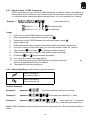
4.1.3. Check of Input and Output Status by SMS Command
GSM Gateway will send a SMS with all actual states as an answer to this command:
Example:
11111
(11111 is a default password for SMS commands)
Answer report will be sent back to that number, SMS command was sent from which. (There
is not registered any event, when SMS massage was delivered without CLIP.) A report will
be transmitted immediately and it will contain actual states of all inputs and outputs.
Example of SMS report: IN1 = 1, IN2 = 0, OUT1 = 0, OUT2 = 1
Notes:
• For security applications, remember that SMS delivery may be slow and unwarranted by
some operators.
• Report contains no time and date nor GSM Gateway number, because SMS centre will add
this information automatically.
30
4.1.4. Check of Input (and Output) Status by Phone (DTMF Command)
By listening signals (see table in chapter 4.2.4 “Phone Control – DTMF Commands“),
inputs can be checked by phone too.
(check input No. 1)
Example No 1:
Use:
1. Call a line, GSM Gateway is connected on which.
2. Enter a password for input/output functions, and
3. If password is valid, GSM Gateway will send confirmation signal
4.
5.
6.
7.
.
Enter
second time
Enter input No.
GSM Gateway will start to signal actual input status periodically (see table).
You can enter another input No again (step 5),
to go to switch control (see chapter 4.2.3).
8. Or you can enter
9. If you stop entering anything, GSM Gateway will send a busy tone
as a programmed time-out is expired.
10. Terminate this mode by hang up.
as soon
Example No. 2:
(Read input No. 1, after it input No. 2, go to switch control, open switch No. 1.)
Note: DTMF check of inputs during common call is not supported now. This mode will be added
in future.
31
4.2. Usage of Universal Outputs
Universal outputs are destined especially for remote control of whichever devices. In the future,
a timer function will also be available. Basic controlling method is by SMS message. Another
possibility is by line or by daily timer. SMS message or DTMF command (see below) must
contain a valid password. Following modes can be selected by programmable parameters (see
chapter 7.4.) for each individually:
0
1
2
3
4
5
Out of use
Basic mode (ON/OFF), OFF state after reset
Basic mode (ON/OFF), ON state after reset
N.O. (normally open), closing for pre-programmed time
N.C. (normally closed), opening for pre-programmed time
Basic mode + daily timer
Closing for pre-programmed time: switch is closed by command and released automatically
after fixed time, which can be programmed by parameter.
Opening for pre-programmed time: switch is opened by command and closed again
automatically after fixed time, which can be programmed by parameter.
4.2.1. Universal Outputs Application Examples
Heating
•
Irrigation
•
Feeding
•
Emergency stop
•
Software reset
•
4.2.2. SMS Commands
SMS Format:
Example no. 1:
11111
(close switch no. 1)
1
1 for switch no. 1
For switching ON,
2 for switch no. 2
For switching OFF
More commands in one SMS can be entered this way:
Example no. 2:
11111
1
2
This command will close switch no. 1 and open switch no. 2.
Notes (valid for both SMS and DTMF control):
• Output status check (incl. inputs) is described in chapter 4.1.3.
• When switch is in required state, command has no effect for it.
• In mode "Closing for pre-programmed time", when switch is ON and a new ON
command is received, it has an extending effect - full time will be counted again from
this moment, when OFF command will come, switch will open immediately.
• By analogy, in mode "Opening for pre-programmed time", when switch is OFF and a new
OFF command is received, it has an extending effect - full time will be counted again from
this moment, when ON command will come, switch will close again immediately.
• All notes above are valid for both SMS and phone (DTMF) control (bellow).
32
4.2.3. Phone Control – DTMF Commands
DTMF commands are very similar to SMS commands. In addition, there is a possibility of
output status check. Moreover, commands can be chained without any limit in this mode,
i.e. switches can be closed and opened several times - e.g. as in example No. 4 below.
(close switch No.1)
Example 1:
Usage
1.
Switch no. 1. 1
For switching ON
Switch no. 2. 2
For switching
Call a line on which GSM Gateway is connected.
2.
3.
4.
5.
6.
Enter a password for input/output functions, and
If password is valid, GSM Gateway will send confirmation signal
.
Enter a switch No.
GSM Gateway will start to signal actual switch status periodically (see bellow).
If you don’t want to change this state, you can enter another switch No. (step 4).
7.
8.
for closing,
for opening of selected switch.
You can enter
GSM Gateway will start to signal a new switch status periodically.
9.
Characters
and
may be entered repeatedly.
10. You can enter a switch No again (step 4).
11. If you stop entering anything, GSM Gateway will send a busy tone
soon as a programmed time-out is expired.
12. Terminate this mode by hanging up.
as
4.2.4. Status Signalling (equal for both inputs and outputs)
Switch is closed or
input level is high (1)
Switch is opened or
input level is low (0)
Another Examples
Example 2:
password
Example 3:
password
Example 4:
password
check both switches state w/o command
close and open switch No. 1, twice
close switch No. 1, close and
open switch No. 2 and then open switch No. 1
Note: DTMF commands during common call are not supported now. This mode will be added in
future.
33
4.2.5. Daily Timer (preliminary)
Daily timer can be programmed for each switch individually. Switch will be closed and
opened daily in pre-programmed time. Up to two “ON” intervals can be programmed, i.e.
two “ON” and two “OFF” times, for each switch.
After reset (when GSM Gateway power is turned on) a switch, programmed to timer
mode, will be closed automatically, if an actual time is corresponding with programmed
“ON” interval.
When GSM Gateway will receive a valid SMS or DTMF command, so it will be executed
and timer will go on (see example bellow):
Example:
Switch 1 will control heating in the flat. It will be pre-programmed to burn in the morning
from 6:00 to 8:00 and in the evening from 17:00 to 23:00. Whenever an occupant plans
to return home earlier, he can send SMS “close switch No. 1”, e.g. at 15:30. Command
will be executed, so that heating will start to burn immediately. At 17:00 nothing will be
changed, and switch will be opened normally at 23:00. Whenever an occupant goes to
bad earlier, he will switch heating off by phone (saving a cost of SMS), so that at 23:00
nothing will be changed, and heating will burn on at 6:00.
34
4.3. Use of Data Mode
4.3.1. Destination:
• For data transfer between two computers (second one can have whichever modem)
• For connecting to Internet
• High speed data (GPRS) mode can be used for connecting to Internet and similar
applications (model 501105)
4.3.2. Serial interface
Serial interface connector is D-Sub 9 pins, female, see fig. 9. It is connected like a
common external modem. All handshake signals are used in data mode. Bit rate is fixed,
see table bellow. All applications must be set to this speed.
Bit rate and data format on the serial interface:
model
501105 (GPRS)
All other models
Bit rate
57600 bit/s
19200 bit/s
Data format
8 bits, no parity, 1 stop bit (8N1)
Note: Bit rate of the serial interface is always higher than data rate from/to GSM network.
Please, do not interchange these parameters!
4.3.3. Data Rate in CSD mode
•
•
•
Maximum data rate in this mode is 9600 or 14400 bit/sec. Real value depends on
GSM network, its load and signal quality.
Fax transmitting and receiving is technically possible, but it is not supported by the
current version of software yet.
High-speed HSCSD mode is not supported.
4.3.4. Data Rate in GPRS mode - only for model 501105
Multislot Class 8 (or 4+1, i.e. 4 Rx + 1 Tx) is able to use up to 4 timeslots for download and 1
timeslot for upload. Maximum theoretical data rate for download is 57600 bis/sec. Real value
varies during connection, and depends on GSM network, its load and signal quality.
This paragraph is valid only for model 501105. For all other models: GPRS is not supported.
4.3.5. How to combine different modes of serial port
Serial port is used by these applications:
• GSM program
• SMS program
• Your Internet browser, if you choose connection to Internet via GSM Gateway
• Your Z-modem or another program, if you connect GSM Gateway to another computer
Basic rule: All applications listed above are excluding each other. It means if you need to
run another one you must terminate current one first. E.g., if you have SMS program running
permanently, and you wish to connect to Internet via GSM Gateway, you must terminate it.
4.3.6. How switching between voice and data modes works
If enabled, data mode has same priority as voice mode. Once occupied by a voice
(phone) connection, GSM Gateway is not ready to handle data as long as this call
continues, and vice versa: once occupied by a data connection, GSM Gateway is not
ready to make a call as long as this data connection lasts.
Important note: current version of firmware for GPRS model is not able to handle any
voice calls during all time of GPRS connection (between ATD to ATH commands).
35
Notes:
• SMS can be transmitted and received during call.
• SMS program reads all new SMS’s stored on SIM card right after start. SMS program
automatically erases SMS’s from SIM card, if you don’t disable it. It is adding all new SMS’s
to file on your PC. Almost unlimited number of SMS’s can be stored and viewed this way.
• Received SMS commands destined for switch control are erased just after execution. They
are recognized automatically and not forwarded to SMS program.
• If any SMS’s excluding these for switch control will come during time, when SMS program is
not running, it can fill SIM card memory. If it will be full and next one will come, an oldest one
will be erased in order to not block path for switch control commands. If switches are not
used, erasing can be disabled by parameter 109, see chapter 7.1
4.3.7. Installation of driver on your PC
Driver must be installed only if you are using the GSM Gateway as a modem – for data
transfer between two PC’s or for connecting to Internet. It is not used for SMS program
and GSM program.
Install driver from enclosed media (floppy or CD) as a conventional modem driver.
Choose Phone and Modem Options in folder Control Panel, and then choose General
and Add. Next browse a path to driver etc. After it, choose driver version:
Driver versions:
ATEUS GSM GATEWAY (analog 19200bps) Driver for all models excluding 101105 (GPRS)
ATEUS GSM GATEWAY (analog 57600bps) Driver for GPRS model, CSD mode *)
ATEUS GSM GATEWAY (GPRS 57600bps) Driver for GPRS model, GPRS mode *)
*) If both modes are required, install both versions.
Important notes:
• It is not recommended that you use the original driver for TC35, available on SIEMENS
web site. This driver allows setting some parameters, which may cause fatal problems within
voice connection.
• In folder Diagnostics button Diagnostics is not working (on both versions of driver)
4.3.8. How to adjust connection to Internet
If you have the driver (see above) and Internet browser installed, it remains only to make
new Connection.
First, choose GSM modem. In case of GPRS model (501105) you can choose CSD or
GPRS connection, see table above. GPRS connection is recommended (check if
operator and used SIM card supports this service).
Next, read all the instructions of your GSM network operator – settings are very different!
Usually you will find detailed step-by-step instructions on your operator’s web site. It is
mainly a number to be dialled and other instructions.
In case of GPRS connection, APN setting is required. Follow GSM operator instructions.
APN is set by command "Extra settings" in folder "Advanced Connection Settings".
Example: at+cgdcont=1,"IP","internet.click.cz"
Attention: For GPRS connection, operator's instructions may contain telephone number
like *99#. In this case, use number *99***1#. Added characters sets PDP context 1,
which is necessary in order to set APN by "Extra settings" command (see above).
36
4.3.9. Serial port functions – for experts
• If GSM Gateway is ready, it will send back all commands (echo)
• Connection is signalled by DCD output
• Incoming data is signalled by RING output and GSM Gateway will transmit:
+CRING: <type>+CLIP:”<clip>”, 145
• It is possible to select after how many rings the GSM Gateway should answer an
incoming data call automatically. You can set it by parameter 181 or the ATS0
command. If you used the ATS0 command, entered value remains until the GSM
Gateway is powered up or reset, or until another change by the AT command. After
the GSM Gateway power up or reset, the function value is set according to
parameter 181. The ATZ and AT&F commands set the function value according to
parameter 181 too. This function has no effect upon incoming voice calls.
• Incoming voice call is not signalled by RING.
• Multiple AT-commands are not supported.
• SMS’s can be handled directly by supported set of AT-commands, including time of
voice call.
• During a voice call, all other AT-commands GSM Gateway refuses by BUSY or ERROR.
4.3.10.
Supported AT-commands
This commands are available on the Internet, www.2n.cz.
4.4. PC-Based SMS Receive/Send
This program works like common e-mailing software, under Microsoft® Windows® 95 and higher.
It can receive, store, edit and send SMS's on the PC, connected to the GSM Gateway by serial
cable. This program is freeware and the actual version is available on the Internet, www.2n.cz.
4.5. Security Centre
This function is under preparation, will be available later as upgrade.
37
5. Installation Instructions for Advanced Users
ATTENTION! DANGER!
Draw out an AC mains cord before opening a cover!
Risk of an electric shock!
WARNING!
All removable parts of cover are earthed with earthing cables!
We do not recommend that you disconnect these cables.
If you do so, remember to reconnect all before closing the cover!
This chapter describes primarily the connection of universal inputs and outputs, the serial
interface and all situations that a technician may face during common servicing.
5.1. Description for GSM Gateways excluding 19'' rack mounted models
Fig. 7: Upper cover face - model 501100E
1. reset pushbutton
2. LED diodes
3. antenna connector
4. hole for SIM handling
Fig.6. Upper cover face - models 5010xxE
1 – reset pushbutton
2 – battery socket - models with backup only
3 – antenna connector
4 - hole for SIM handling
38
5.1.1. Upper Cover Face
Reset Pushbutton:
The button can be pushed using a tool such as a match, pencil, etc. and has the following
functions:
• By pushing the button once during the GSM Gateway operation you reset the equipment.
The program is terminated and restarted. This function has no influence on the GSM
Gateway set-up stored in the GSM Gateway memory.
• By keeping the button pushed during the GSM Gateway power-on you enter a special
mode where you can load a new software version into the GSM Gateway. For details
refer to the “Control Software Upgrade“ chapter.
Antenna Connector:
On models 501061E and 501063E, this connector is not earthed! While the GSM Gateway
metal cover is connected with the protective socket wire and thus earthed (as Security
Regulations require), the GSM Gateway electronic circuits (on these models) are not
earthed. This is advantageous when a PC is connected to the GSM Gateway: by connecting
a PC to the RS-232C serial interface (see later) that is earthed to another ground potential
(another mains circuit), you earth the GSM Gateway electronic equipment through this PC
and data transmission is not interfered by a ground potential difference. In that case, you
need no opto-coupler isolation of the serial port even if the PC is tens of metres
distant. This, of course, is possible only if the antenna connector does not get in touch with
the GSM Gateway cover or the earthing thereof to another ground potential.
On models 501100E and 501105E, whole electronics including antenna connector is
earthed (connected to PE pin of AC plug and to all parts of metallic cover).
SIM Card Holder:
To insert or replace your SIM card remove the upper cover face with a tool (crosshead
screwdriver No.1). This gives your SIM card a better protection against misappropriation.
5.1.2. Bottom Cover Face
Telephone Line Connector:
This RJ-12 connector is identical in all models. The
telephone line is connected to the central pair of pins
(two pins nearest to the connector axis). The polarity
is arbitrary. The galvanic isolation of the PBX and
GSM Gateway is located as follows:
• In the PBX with the PBX CO line model,
• In the GSM Gateway with the PBX subscriber line
model.
Mains Supply Connector:
The mains supply connector is used for PCs and is
thus identical in practically all countries. In all
countries, a power cable is used whose other end
(wall socket end) meets local regulations and socket
dimensions. The protective pin (in the middle) is
connected with the GSM Gateway cover and used
as the first over voltage protection stage for the
telephone line circuits. For security and functional
reasons, it is necessary that the pins earthed!
39
Fig. 8.: Bottom cover face:
3 – telephone line connector
4 – AC mains connector
5 – RS-232C serial interface connector
RS-232C Serial Interface Connector:
Since the GSM Gateway in its data mode is a regular modem, the connector pins are
exactly the same as in an ordinary modem, see Fig. 9. For the PC connection, a non-crossover (1:1) extension cable – the same as for the connection of a PC and external modem –
is used. The maximum cable length is in excess of 30 metres and depends on the PC – it
may be a little trial and error is needed to find an exact maximum length.
Fig. 9.: Serial RS-232C interface connector
54321
9876
1
2
3
4
5
6
7
8
9
DCD
RxD
TxD
DTR
GND
DSR
RTS
CTS
RI
5.1.3. Front Cover Part Disassembly
The remaining elements such as the fuse or the input and output terminals are not
accessible until you remove the front cover part, which is clicked into the bottom cover
part slots and held by its own flexibility. First remove the upper cover face to grasp the
front cover part easily and pull it out. The front cover part includes a panel with LED
indicators – the connection cable is detachable from the motherboard.
Fig. 10: Front cover disassembly
40
5.2. Description for 19'' rack mounted models
Fig. 11:. 19" rack mounted model - front panel
1. LED Indicators (see chapter 2.8.3 for details)
2. Antenna connector
3. RESET pushbutton
4. Serial interface connector
5. Telephone line connector
41
5.3. Description of GSM Gateway PCB
Fig. 12.: Printed Circuit Board (PCB) of GSM Gateway model 501063E (for external line of PBX, with
battery backup)
42
Explanatory Notes
1. TL1 – Reset button
2. Input and output terminal block
3. P1 - fuse for battery, in socket, value T1A, type FSKK
4. U9 – main micro controller in the socket
5. U5 – auxiliary micro controller in the socket
6. L4 - DC-DC converter transformer
7. L6 - AC Mains transformer
8. Mains EMC filter circuit
9. P2 - Mains fuse in socket, value T 200 mA, type FSKK
10. 2 x 10,000 A surge arrester – first stage of telephone line circuit over voltage protection
11. X7 – telephone line RJ-12 connector
12. X8 – mains supply connector
13. J1 – RS-232C serial interface connector
14. U19 – EEPROM containing GSM Gateway programmed parameters
15. B1 – battery holder with CR2032 type lithium coin battery
16. Beeper for failure signalling
17. JP4 – LED panel connector
18. U22 – programmable serial interface circuit (GAL) in the socket
19. SIEMENS ® GSM module
20. X10 – SIM card holder
21. Antenna connector
Description of Terminals
Universal input No. 2
Universal input No. 1
Ground
DC output +12 V
Ground
Switch No. 2 – active ON contact (N.O. - Normally Open)
Switch No. 2 – contact connected with ground
Switch No. 1 – active OFF contact (N.C. – Normally Closed)
Switch No. 1 – common contact
Switch No. 1 – active ON contact (N.O. - Normally Open)
- Terminal of battery (Ground)
+ Terminal of battery (+12V)
43
Fig. 13.: Printed Circuit Board (PCB) of GSM Gateway model 501061E (for local line of PBX (extension),
with battery backup)
44
Explanatory Notes
1. TL1 – Reset button
2. Input and output terminal block
3. P1 - fuse for battery, in socket, value T1A, type FSKK
4. U9 – main micro controller in the socket
5. U8 – auxiliary micro controller in the socket
6. L4 - DC-DC converter transformer
7. L6 - AC Mains transformer
8. Mains EMC filter circuit
9. P2 - Mains fuse in socket, value T 200 mA, type FSKK
10. 2 x 10,000 A surge arrester – first stage of telephone line circuit over voltage protection
11. X7 – telephone line RJ-12 connector
12. X8 – mains supply connector
13. J1 – RS-232C serial interface connector
14. U19 – EEPROM containing GSM Gateway programmed parameters
15. B1 – battery holder with CR2032 type lithium coin battery
16. Beeper for failure signalling
17. JP4 – LED panel connector
18. U22 – programmable serial interface circuit (GAL) in the socket
19. SIEMENS ® GSM module
20. X10 – SIM card holder
21. Antenna connector
Description of Terminals
Universal input No. 2
Universal input No. 1
Ground
DC output +12 V
Ground
Switch No. 2 – active ON contact (N.O. - Normally Open)
Switch No. 2 – contact connected with ground
Switch No. 1 – active OFF contact (N.C. – Normally Closed)
Switch No. 1 – common contact
Switch No. 1 – active ON contact (N.O. - Normally Open)
- Terminal of battery (Ground)
+ Terminal of battery (+12V)
.
45
Fig. 14.: Printed Circuit Board (PCB) of 19" rack mounted GSM Gateway model 504063E (for external
line of PBX)
46
Explanatory Notes
1. X8 - Supply bus connector
2. P1 - supply fuse in socket, value T1A, type FSKK
3. SIEMENS ® GSM module
4. JP1 - diagnostic connector of power section
5. X9 - diagnostic connector of digital section
6. U5 – programmable serial interface circuit (GAL) in the socket
7. X10 – SIM card holder
8. K1, K2 - universal output relays (optional only)
9. Input and output terminal block
10. LED lamps
11. TL1 – Reset button
12. J1 – RS-232C serial interface connector
13. X7 – telephone line RJ-12 connector
14. 2 x 10,000 A surge arrester – first stage of telephone line circuit over voltage protection
15. Line circuit for external line of PBX
16. U7 – auxiliary micro controller in the socket
17. U12 – main micro controller in the socket
18. U14 – EEPROM containing GSM Gateway programmed parameters
19. L5 - DC-DC converter transformer
Description of Terminals
Universal input No. 2
Universal input No. 1
Ground
DC output +12 V
Ground
Switch No. 2 – active ON contact (N.O. - Normally Open)
Switch No. 2 – contact connected with ground
Switch No. 1 – active OFF contact (N.C. – Normally Closed)
Switch No. 1 – common contact
Switch No. 1 – active ON contact (N.O. - Normally Open)
47
X5
X4
X3
X2
X1
Fig. 15.: Printed Circuit Board (PCB) of 19" rack mounted GSM Gateway model 504061E, for internal line
of PBX (extension).
48
Explanatory Notes
1. X8 - Supply bus connector
2. P1 - supply fuse in socket, value T1A, type FSKK
3. SIEMENS ® GSM module
4. JP1 - diagnostic connector of power section
5. X9 - diagnostic connector of digital section
6. U5 – programmable serial interface circuit (GAL) in the socket
7. X10 – SIM card holder
8. K1, K2 - universal output relays (optional only)
9. Input and output terminal block
10. LED lamps
11. TL1 – Reset button
12. J1 – RS-232C serial interface connector
13. X7 – telephone line RJ-12 connector
14. 2 x 10,000 A surge arrester – first stage of telephone line circuit over voltage protection
15. Line circuit for internal line of PBX (extension)
16. U7 – auxiliary micro controller in the socket
17. U12 – main micro controller in the socket
18. U14 – EEPROM containing GSM Gateway programmed parameters
19. L5 - DC-DC converter transformer
Description of Terminals
Universal input No. 2
Universal input No. 1
Ground
DC output +12 V
Ground
Switch No. 2 – active ON contact (N.O. - Normally Open)
Switch No. 2 – contact connected with ground
Switch No. 1 – active OFF contact (N.C. – Normally Closed)
Switch No. 1 – common contact
Switch No. 1 – active ON contact (N.O. - Normally Open)
49
X5
X4
X3
X2
X1
Fig.16: Printed Circuit Board (PCB) of dual-band GSM Gateway models 501100E and 501105E,
for external line of PBX. A new PCB issues (6, 7 or higher).
50
Explanatory Notes
1. LED indicators
2. TL1 - Reset pushbutton
3. Input and output terminal block
4. SIEMENS ® GSM module TC35 or MC35
5. Mains transformer
6. P1 - Mains fuse – T 200 m A
7. BJ1 - 2 x 10,000 A surge arrester – first stage of telephone line circuit overvoltage protection
8. X6 – telephone line RJ-12 connector
9. X7 – mains supply connector
10. J2 – RS-232C serial interface connector
11. JP1 - diagnostic connector of power part
12. U14 – programmable serial interface circuit (GAL) in the socket
13. U16 – EEPROM containing GSM Gateway programmed parameters
14. X8 - diagnostic connector of digital part
15. U15 – auxiliary micro controller in the socket
16. U10 – main micro controller in the socket
17. X9 – SIM card holder
18. Antenna connector
Description of Terminals
Universal input No. 2
Universal input No. 1
Ground
DC output +12 V
Ground
Switch No. 2 – active ON contact (N.O. - Normally Open)
Switch No. 2 – contact connected with ground
Switch No. 1 – active OFF contact (N.C. – Normally Closed)
Switch No. 1 – common contact
Switch No. 1 – active ON contact (N.O. - Normally Open)
X5
X4
X3
X2
X1
Notes:
• The + 12V voltage output is non-stabilized. For the maximum load see technical data. This
can be used for supplying the PIR sensor, etc.
• The main microcontroller can be removed with a specialized tool only. Usually, it is not
necessary because the microcomputer can be reprogrammed in the GSM Gateway. Using
another tool may cause damage to or destroy the PCB!
• The main microcontroller contains a serial number of GSM Gateway as well as a protected
code. If erased by a programming tool unlike GSM program, it will not work and these data
cannot be re-programmed by GSM program again!
51
Fig.17: Printed Circuit Board (PCB) of dual-band GSM Gateway models 501100E and 501105E,
for external line of PBX. Older issues (up to 5).
52
Explanatory Notes
1. LED indicators
2. TL1 - Reset pushbutton
3. Input and output terminal block
4. SIEMENS ® GSM module TC35 or MC35
5. Mains transformer
6. P1 - Mains fuse – T 200 m A
7. BJ1 - 2 x 10,000 A surge arrester – first stage of telephone line circuit overvoltage protection
8. X6 – telephone line RJ-12 connector
9. X7 – mains supply connector
10. J2 – RS-232C serial interface connector
11. B1 – battery holder with CR2032 type lithium coin battery
12. U14 – programmable serial interface circuit (GAL) in the socket
13. U16 – EEPROM containing GSM Gateway programmed parameters
14. JP1 - diagnostic connector of power part
15. X8 - diagnostic connector of digital part
16. U15 – auxiliary micro controller in the socket
17. U10 – main micro controller in the socket
18. X9 – SIM card holder
19. Antenna connector
Description of Terminals (the same as for new issues)
Universal input No. 2
Universal input No. 1
Ground
DC output +12 V
Ground
Switch No. 2 – active ON contact (N.O. - Normally Open)
Switch No. 2 – contact connected with ground
Switch No. 1 – active OFF contact (N.C. – Normally Closed)
Switch No. 1 – common contact
Switch No. 1 – active ON contact (N.O. - Normally Open)
53
X5
X4
X3
X2
X1
5.4. Connection of Universal Inputs and Outputs
5.4.1. Connection of Universal Inputs
Both input terminals (location see chapter 5.3, PCB layout description) are compatible
with most systems. Usually they are controlled by contact; both N.C. (Normally Closed)
and N.O. (Normally Open) contacts can be used. Contact should be connected between
selected input terminal and GND terminal. Open contact is evaluated as "1" level, closed
contact as "0" level. When a voltage source is connected (e.g. TTL signal), GND
terminals of GSM Gateway and signal source (e.g. computer) must be connected.
Voltage levels "0" and "1" are TTL -compatible (see technical parameters). Inputs can be
driven by higher voltages e.g. 12V (see technical parameters), without damage.
5.4.2. Connection of Universal Outputs
All GSM Gateway models, described in this manual, are equipped with two universal
outputs. Output No. 1 is an insulated contact of relay; Output No 2 is open-collector
output (any combination can be provided on request, e.g. two relays etc.) Application
examples see chapter 4.2. Relay output is more flexible, because of its insulation and
both N.C. (Normally Closed) and N.O. (Normally Open) contacts option. But a low-cost,
open-collector output is good enough for a lot of applications, too.
54
Fig. 18 shows an example of relay output application for computer reset. This switch can
drive any low-voltage circuit up to 48 V AC or DC - e.g. thermostat, tape recorder, camera
etc. Controlled equipment and GSM Gateway will remain insulated, but this insulation is
not designed to insulate against such voltages as 120 or 230V AC mains.
Fig. 18. Relay output
Application example
ATTENTION! Don't connect any output terminals
to such voltages as 120 or 230V AC mains!!
Fig. 19 shows another application example. A high power can be switched in this way, by
SSR (Solid State Relay) module. A SSR module is a standard product of many
semiconductor vendors and it is available for different currents (10A typically); threephase SSRs are available too. Fig. 18 shows, that open-collector output is good enough
for SSR input driving. GSM Gateway +12V DC output terminal provides a necessary
supply voltage for SSR module input. In addition, SSR module provides high-voltage
insulation between GSM Gateway and current consumer.
Fig. 19. Open-collector output (switch No. 2) used as a driver for SSR module.
ATTENTION! Qualified persons must only connect circuits like
this, which are operating with 120V, 230V or any other AC
mains, or with any other dangerous voltages, in accordance
with local regulations and laws in your country!
If there is need of a second relay output, common type low-power relay with 12V coil can
be connected in the same way, as a SSR input on fig. 19.
55
5.5. Back-Up Battery, Replacement
This paragraph applies to backed-up models 501061E and 501063E.
Normally, a back-up battery, ordering No. 910121090, is used. This is a maintenance-free lead
battery pack 12V / 1,2Ah (two 6V blocks) with metallic cover. Arrangement of components and
cables inside this cover is on drawing no. 20.
ATTENTION!
Accumulators has a very high short-circuit current!
Don't short it anyway! Risk of explosion!
Instructions for replacement:
1. Switch off. Draw out an interconnecting cable from GSM Gateway.
2. Remove the upper cover face of battery cover, grasp the front cover part and pull it out.
3. Draw out all cables from accumulators.
4. Slacken nuts, which are holding a double U-bolt.
5. Remove double U-bolt and accumulators.
6. Place new accumulators; place the double U-bolt back into proper position.
7. Tighten all three nuts.
8. Connect all cables back to accumulators; see drawing no. 20.
9. Check carefully the connection, especially a polarity of outgoing cable. Positive terminal
of battery must be connected with a red labelled wire!!!
10. Place the front cover back and screw up the upper cover face.
11. Connect a cable to the connector on GSM Gateway and switch on.
Fuse:
A tube fuse T 1A, 5x20mm in a fuse holder protects an accumulator against short circuit.
Replace this fuse only with proper type!
Different accumulator:
Circuits in GSM Gateway are designed to handle 12V / 1,2Ah maintenance-free lead battery.
This battery is charged and checked automatically, the GSM Gateway indicates the charging
and emergency statuses and stores these events in the service buffer. Also a different lead
battery with a nominal voltage 12V and a capacity of 1 to 2Ah or a set of 10 NiCd or NiMH cells
of the capacity from 600 to 1,600mAh can be used too. Of course, a manufacturer cannot
guarantee a proper charging, if the battery parameters are too different. Especially, a battery of
a higher capacity may not reach an end-of-charge voltage. It may cause a permanent charging,
and it may damage the battery! Such battery must be charged externally. In this case, the
charging function has to be disabled by software – see chapter 7.1, parameter 170. With
software disabled charging, an external 12V power (see technical parameters) can be applied
too.
Connection method:
Terminal X1, see Description of Terminals on Fig. 12, is destined for battery connection. This
terminal is normally occupied by cable, connected to a connector on GSM Gateway cover, for
easier connection with standard battery pack. Remove this cable and use X1, if necessary. In
this case, put conductors through the GSM Gateway side hole.
56
Double U-bolt
Accumulators
Nuts
Switch
Fuse T 1A
(In this drawing, the fuse is shifted little
to right for better view.)
accumulator cable
Fig. 20.: Arrangement of components and cables inside battery cover
5.6. Fuse Exchange
Spare fuses are enclosed to all backed-up models. The fuse may blow e.g. when battery is
connected in reverse polarity. If a lamp on GSM “Battery error” lights and a battery voltage is
good (ca 12V) and a fuse in a battery cover if good after all, follow these instructions:
1. Draw out an AC power cable.
2. Disconnect an accumulator and open a cover.
3. Remove a battery fuse (see corresponding PCB layout) and check it.
4. Place a good fuse, value T1A, type FSKK into this socket.
5. Close a cover and connect a battery – check a polarity!
6. Connect an AC power cable.
General rules:
• Use only a fuse of the same value and type.
• Disconnect the AC power cable and the accumulator while replacing any fuse.
• Fuse for AC power can be replaced only by service which is able to check such parameters
as power consumption, DC voltages etc.
• If a fuse fails again, manufacturer must repair equipment.
57
5.7. Lithium Battery Exchange
Models 501100E and 501105E of issue 6 or higher are not equipped with lithium battery. Real
time clock circuit is inside the GSM module and it is backed up by Gold-Cap (multilayer
capacitor of large capacity) for a several hours. This chapter can be applied for older issues and
models 501061E and 501063E.
ATTENTION!
Explosion risk when the lithium battery is replaced incorrectly. Replace only by the
same or equivalent type according the producer's recommendation. Handle the
used batteries according to the producer's instructions.
On-board lithium battery is used for RTC (Real Time Clock) during AC main failure only. It is not
necessary for GSM Gateway operation. A totally discharged battery may have such effects as
wrong time information (which is displayed after running GSM program in right top corner of
window). Wrong time and date information will be in service buffer records, too. Lifetime of
battery is more than three years. After this time, a battery change is recommended, or its check
(min. voltage 2.9V) at least.
To replace lithium battery, disconnect GSM Gateway from mains, open its cover (see chapter
5.1.3.), then remove an old battery using a proper tool and insert a new one.
Battery type: CR2032.
DANGER!
Do not use metallic tools to handle both old and new lithium
batteries during replacement! Don't short it anyway!
Risk of explosion!
Recycle or dispose of old batteries in accordance with law and local regulations!
5.8. Microcomputer Exchange
Under preparation
58
6. Programming
6.1. How to Program
You can program your GSM Gateway in three ways: with a telephone, PC, or remote by PC as
listed in the table below:
Phone
PC
PC,
remote
Parameters with exception
of I2CR table and SMS texts:
!
!
!
I2CR table and SMS texts:
!
!
!
Reading of all parameters:
!
!
Service buffer read:
!
!
Upgrade of GSM Gateway firmware:
!
Programming method:
Programming:
6.2. Before Programming
•
•
•
•
•
Using the chapter 2.8, make sure, that the GSM Gateway works.
Learn the default set-up of programmable parameters. Keep them as they are unless you need
to change them.
Decide in which way you will program the GSM Gateway. If you can use a PC, then use it.
Select the most convenient of the initialising files. Open it with the appropriate program, study
the notes therein and change those parameters only that you are not satisfied with.
If you use the telephone programming, fill all values to be changed into the parameter table
fields (chapter 7).
If the GSM Gateway is not brand-new, make sure that you know the correct service
password. If you are not quite sure, perform the full initialisation!
59
6.3. Handset-Based Programming
6.3.1. Requirements and Recommendations
•
•
•
You need another extension of the same PBX and a tone-dialling telephone set for
programming.
Use the telephone-based programming only if you do not want to set up many
parameters. Remember that you do not have any feedback with a telephone!
Complete the prepared form first – think before programming!
6.3.2. Entering Programming Mode
• Pick up the handset. If you have a phone connected directly with GSM Gateway, go to
next step. Otherwise, dial the number to access GSM Gateway. *)
. You cannot program during the current
• Wait until you can hear the dial tone
call, or if the GSM Gateway requires a PIN or PUK code.
•
•
•
•
To get into the programming mode enter the service password and the
character.
The GSM Gateway transmits a confirmation .
If you make a mistake while entering the password, cancel the entering by hangingcharacter cannot be used) and start again.
up (the
The service password is ‘12345‘ by default. We recommend changing the password
to protect your equipment against unauthorized persons. If you forget the password,
your data will not get lost, but you will have to contact the manufacturer.
If you enter an incorrect password that is not bared by sorting table, the GSM
Gateway dials the number and may get through somewhere. This, however, is
almost improbable. In case of GSM Gateway model for external line and pulse dialing
selected, there is no such a risk; GSM Gateway sends busy tone if any other number
than correct password is entered.
Example:
correct
password
,
you
enter
incorrectly
, the number is dialled and you will get through to the
emergency line 112.
*) Note: You must access GSM Gateway by its line interface. Programming by GSM
connection (incoming call) is not possible.
6.3.3. Telephone-Based Programming
Once you have entered the programming mode, you can change all parameters or
more parameters in any sequence, except for SMS message texts or I2CR table
parameters. It is easy – just enter the parameter number and then the parameter value. Use
the
as separator ("Enter").
Each parameter number has three to four digits (refer to the Parameter Tables). After
are entered, the GSM Gateway sends a confirmation
signal if such
the number and
parameter exists and is available in the particular model and software version. If it is not
available, the GSM Gateway transmits a rejection signal
another
are entered, the GSM Gateway sends a storing
. After the value and
signal if the value lies in
the allowed interval. If not, the GSM Gateway transmits a rejection signal
. The
programmed values are stored immediately during the storing signal
transmission.
60
Programming Example:
Sets the GSM Gateway clock at 12 o’clock, 30 minutes, 0 seconds.
Important warning!!! While setting time parameters note the units they are
set in – seconds or milliseconds. Since you cannot enter the decimal point
from your telephone, milliseconds must be used wherever seconds are too
rough. However, you cannot enter any number in the allowed interval
(173 ms, e.g.), but you have to respect the step prescribed for the particular
parameter. If one step is 100 ms, e.g., your value must end with two zeroes.
Example:
Parameter 243, tariff pulse length, has a step of 10 ms. Hence you cannot enter 66 ms, e.g., but
70 ms. To set 1 second, you have to enter 1000.
6.3.4. Programming of Multi-Parameter Line Tables
Some parameters constitute a two-dimension table (the Call Sorting Table, e.g.). In the
table, one line has a three-digit number and can contain up to 10 parameters. The
individual parameters on the line have a four-digit number, differing in the last digit. They
can be entered as follows:
•
•
Each parameter separately: follow the preceding procedure, but use a four-digit
parameter number;
More parameters in sequence: this method is quicker and is as follows:
1) First enter a three-digit number of the parameter line.
are entered, the GSM Gateway sends a confirmation signal
2) After the number and
if such parameter line exists and is available in the particular model and software
version. If it is not available, the GSM Gateway transmits a rejection signal
3) Then enter the first parameter and
.
. The GSM Gateway transmits a storing signal
if the parameter is in the allowed interval. This signal is different from the
2
common storing signal
(refer to the Signalling During Programming Table) and
indicates that the value has been stored and the following parameter is awaited.
4) The programmed value is stored immediately during transmission of the storing
signal 2
or
.
5) Then, you can enter the next parameter and
. The procedure is the same.
6) To signal that this was the last parameter to be programmed, press
.
and
7) The remaining parameters on the line will not be changed.
8) If you enter all parameters, the GSM Gateway transmits a common storing signal
after the last one.
9) Therefore, you cannot pass onto the next line by simply entering parameters; you
have to enter the line number.
10) To program a table line in the above-described way, you always have to start with the
first parameter.
Example:
Stores the first 3 parameters into line 501 (to be specific, the 0602 prefix is allowed and the call
will not be stored in the buffer).
61
6.3.5. Programming Error
• If you make a mistake while entering a number (no matter whether a parameter
number or a value) and find it before you press
programming step using the
, you can cancel the whole
character.
•
If the GSM Gateway transmits a rejection signal
parameter number even if the value was incorrect.
•
If, while programming more parameters at the same time (table line) using the above
mentioned procedure, you make a mistake in the third parameter, e.g., and the GSM
, you have to re-enter the
, all correctly entered parameters have
Gateway transmits a rejection signal
already been stored and you need not re-enter them. You can either re-enter the whole
line or enter the remaining parameters individually.
•
If you program and the GSM Gateway stores a value that you do not want, you can
re-enter the value correctly, of course, i.e. re-enter the parameter number, etc.
6.3.6. Erasing of parameters
•
•
•
and once again
To erase parameter, enter its number,
.
Only parameters, which can be empty (see Parameter Tables, chapter 7), can be erased this
way. In case of parameter, which cannot be empty (defined range, e.g. receiving volume and
.
the like), GSM Gateway transmits a rejection signal
Erasing parameters in the Call Sorting Table: If you will erase some prefix, i.e. the first
parameter on the row, all parameters on this row will be erased (or initialized). If you will
enter row number (e.g. 501) or number of first parameter (e.g. 5011), it has the same effect.
But, if you will enter number of another parameter (e.g. 5010), only this parameter will be
erased.
6.3.7. Programming End
Hang up to terminate programming. After the programming end make sure that the GSM
Gateway works as you want it to. Store the completed programming form of configuration
file safe.
6.3.8. Signalling During Telephone-Based Programming
Signal
Name
Meaning
• After valid service password
Confirmation
• After valid parameter No.
• After invalid parameter No.
Rejection
• After invalid parameter value
(error)
• After cancelling of anything by
Storing
Storing 2
• Value is valid and stored
• Value is valid and stored, next parameter may be entered
62
6.4. PC - Based Programming via serial interface
6.4.1. Connecting to PC, starting of GSM program
Connect GSM Gateway and your PC or notebook by RS-232C Serial Interface. Use an
enclosed serial cable or another common 1:1 male/female serial cable. Run GSM
program (actual version is available on internet). Program works without connected GSM
Gateway too (prearrangement of set-up, demo...). It has three basic functions, described
below.
6.4.2. Programming tool
Basic function of GSM program is to view and edit all parameters of GSM Gateway.
Parameters are grouped in windows, which are according with parameter tables in
chapter 7 of this manual. Help and hints are available for all parameters, as well as a
choice of basic set-up. You can add your own notes and save all settings as a file for
future use. Parameters can be up- or downloaded, but some are read-only or write-only;
e.g. passwords cannot be read, and serial number cannot be overwritten.
6.4.3. Viewing of service buffer
Complete content of service buffer can be viewed on PC and stored as a file - all
monitored events (up to 200 in all) incl. time and date of each. When service buffer is full,
oldest events are overwritten by newest; i.e. buffer is permanently full of "fresh"
information. Watched event types can be selected by mask, see chapter 7.8.
6.4.4. Upgrade of GSM Gateway firmware
GSM Gateway is equipped with ISP (In System Programming) feature. You can
"upgrade" it whenever you wish. Actual version of firmware is available on Internet (free).
How to upgrade your GSM Gateway firmware:
1) Download actual version of GSM program and Hex file for upgrade from www.2n.cz
2) Install GSM program on your PC, connect GSM Gateway to serial port
3) Run GSM program and select used COM
4) Check connection - GSM program must be able to read settings from GSM
Gateway
5) Turn GSM Gateway OFF (in a case of model with battery back-up, disconnect
battery too)
6) Press RESTET button and hold it while turning GSM Gateway ON
7) Most lamps on GSM Gateway must light up - upgrade mode is activated
8) Make an upgrade now - button Hex in the top toolbar of GSM program window.
63
6.5. Remote Programming by PC
6.5.1. Remote Supervision Purpose
Remote supervision allows reading and changing the GSM Gateway configuration
remotely as well as reading the contents of the service buffer, thus saving time of
servicing technicians enabling them to solve some problems remotely. For remote
supervision, the same GSM software is used as for local setting using a serial interface.
All features are absolutely identical with the exception of the GSM Gateway firmware
upgrade, which cannot be done remotely.
6.5.2. What You Need to Run Remote Supervision
On client‘s premises:
1. The GSM Gateway must be equipped with a SIM card supporting data transmission.
2. The GSM Gateway must contain firmware of version 2.36 and up.
3. Parameters required for remote supervision must be selected in the GSM Gateway.
In Supervision Center:
1. You need to know the client‘s GSM Gateway service password.
2. A GSM program of version 1.05 or up must be installed in the PC.
3. The PC must be equipped with a reliable modem (analog, ISDN, or GSM), or a GSM
Gateway made by 2N, which works in the data mode. If the PC is equipped with an analog
modem, it has to be connected to a CLIP-sending exchange (calling line identification
presentation).
4. The ‚incognito‘ function may not be activated on the Supervision Center side.
Important warning!
Once programmed for remote supervision by selected line, client’s GSM Gateway cannot
receive an ordinary call from this line. The GSM Gateway with the said selection regards
every call containing the Supervision Center CLIP as a remote supervision attempt.
Hence, to make such a call, you should use another line or another SIM card, or the
‚incognito‘ function, or make a call in direction from client’s GSM Gateway to the
Supervision Center.
Important recommendations
1. Select a reliable telephone line or SIM card for connection whose number will not be
changed in the future (will not be renumbered).
2. You are recommended to use another GSM Gateway or a GSM modem rather than a
fixed line modem to establish connection much more quickly.
3. The GSM Gateway or GSM modem in the Supervision Center should be equipped with a
SIM card with a separate number for data connections (necessary if you use remote
supervision with callback to a GSM Gateway of different operator).
4. A connection within one GSM network is more reliable than a connection between different
operators.
5. If you are forced to use two different operators for remote supervision, read the “Data
Connection Problems” chapter carefully.
6.5.3. What Is "Callback"
In case of normal supervision call, the calling party, i.e. the Supervision Center covers
data transmission costs. To avoid billing complications, the GSM Gateway can establish
remote supervision connection on the account of the client’s GSM Gateway. It is the socalled callback:
64
1. The Supervision Center GSM Gateway or modem “calls” the client’s GSM Gateway.
2. The called GSM Gateway identifies the Supervision Center CLIP as a callback request
and rejects the incoming call immediately. Therefore, this request is free.
3. Right after that, the called GSM Gateway calls the Supervision Center number that sent
the request. If unsuccessful, it retries several times later.
4. The Supervision Center GSM Gateway or modem waits for this callback. Having received
it, it establishes data connection. Remote supervision is possible upon entering of the
valid service password.
6.5.4. Remote Supervision from 2N Supervision Center
You need not configure anything for this service; all you have to do is to set parameter
930 to enable remote supervision. Necessary parameters are hidden (cannot be
programmed). Callback is always used for this connection.
6.5.5. Overview of Remote Supervision Parameters
One common parameter enables / disables remote supervision, and four sets of
parameters follows:
• CLIP - number of remote supervision center,
• callback enabled / disabled,
• number for callback.
These four sets enables to make remote supervision call from up to four different sites.
Parameters are described in details in chapter 7.9 - Service parameters.
65
6.5.6. How to make GSM Gateway ready for Remote Supervision
1
2
3
4
5
7
6
8
11
9
12
10
1. Connect the GSM Gateway to your PC and run the GSM program.
2. Switch into the on-line mode.
3. If the connection fails, select the correct serial port number in the ‘Setting’ menu.
4. Read the GSM Gateway setup.
5. Open the ‘Service Parameters’ item.
6. Open the remote supervision parameter folder.
7. Make sure that remote supervision is enabled. If not, enable it.
8. Enter the number of the modem or GSM Gateway, which is used for remote supervision.
9. If you select the callback item, and the GSM Gateway, which is used for remote supervision,
has a separate data number, enter the data number in the right-hand column.
10. You can enter up to 4 numbers to be used for remote supervision.
11. Remember to save the setup back into the GSM Gateway.
12. Switch into the off-line status.
Important recommendation:
You are recommended to make this setup before installing the GSM Gateway at the client’s.
With older types of GSM Gateways already installed, you are advised to make this setup
immediately after software upgrade to a version supporting remote supervision – 2.36 and up.
66
6.5.7. How to Run Remote Supervision
1
2
10
3
11
5
4
6
7
8
9
1.
2.
3.
4.
5.
6.
7.
8.
Run the GSM program on the Remote Supervision Center PC.
Click on this icon to open the list of supervised GSM Gateways.
The list may include subfolders in multiple levels.
Click on this key to create a subfolder.
Click on this key to create a new item in the list.
Enter client's name, company etc. here.
Enter the respective GSM Gateway telephone number here.
WARNING! Settings here must correspond with the respective GSM Gateway setup in order
that the remote supervision connection can be established successfully!
9. Click on this key to save the record in the list.
10. Click on this key to establish remote supervision through your modem.
11. Click on this key to establish remoter supervision through your GSM Gateway.
Important cautions:
• Connection establishing is the quickest without callback or with a GSM – GSM connection
made within one and the same GSM network, which usually takes only a few seconds. With
callback and different GSM operators, the establishing may take up to several minutes.
• With callback, the PC does not check whether the callback comes from the GSM Gateway you
sent the request to. Hence, if you, e.g., try to establish connection with one GSM Gateway and
cancel the attempt before getting through, and then you try to make connection with another
GSM Gateway, you should make sure from which of the gateways the callback is coming!
67
6.5.8. Remote Supervision Establishing – Flow Chart
68
6.5.9. Data Connection Problems
GSM data transmission is different from analog CO line data transmission: it is necessary
to specify in advance whether the case will be voice, data or fax connection. With the
connection once established, the connection mode cannot be changed. Therefore, the
calling party should select the required connection before establishing it and this
information should get to the target GSM network operator through all networks involved.
Experience from other countries and operators show that this is quite impossible in some
cases and not fully reliable in other cases. For an overview of remote supervision options
with/without callback see the table below.
Service
Client’s GSM Gateway
No Callback
With Callback
GSM
Gateway
One and the same GSM
operator
No problems
No problems, you need not
select the data number for
callback.
GSM
Gateway
Another GSM operator,
SIM has no special data
number.
No guarantee; it works if both
operators are able to establish
data connection between each
other, in the direction from
service to client.
No problems if the callback
data number is used.
GSM
Gateway
Another GSM operator,
SIM has a special data
number.
No problems if the called GSM
Gateway data number is used.
No problems if the callback
data number is used.
ISDN
modem
Any GSM operator
No guarantee; it works only if
both operators are able to
establish data connection
between each other, in the
direction from service to client.
No guarantee; it works only if
both operators are able to
establish data connection
between each other, in the
direction from client to service.
Analog
modem *)
Any GSM operator, SIM
has a data number.
No problems if the called GSM
Gateway data number is used.
No problems
Analog
modem *)
Any GSM operator, SIM
has no data number.
Not applicable
No problems
*) IMPORTANT! The analog modem must be connected to a CLIP-sending PBX.
Table – SIM Card Identification Options for Outgoing Calls:
Voice number Data number
YES
NO
YES
YES
NO
YES
Number used for outgoing call identification:
voice number
voice number
data number
Note: The SIM card can have another number for fax calls, which is no important for remote
supervision.
69
7. Parameter Tables
7.1. Basic Parameters
Min.
Max.
Def.
PIN entering mode
PIN – value
Par.
No.
101
102
0
4 dig.
1
8 dig.
1
-
CLIR – incognito
103
0
2
0
Volume - direction to GSM
Volume - direction from GSM
Roaming enable/disable
104
105
106
1
1
0
5
5
1
3
3
0
Incoming calls rejection
107
0
1
1
GSM signal level indication
Delete SMS when SIM is full
108
109
0
1
0
0
1
1
Silence after dialing
111
0
25500
0
End of dialling signal length
Dialling end time-out
Switchboard operator number
112
113
114
0
2550 200
2000 15000 6000
Max. 8 digits
Interantional prefix
115
1 dig. 4 dig.
00
Country code
116
1 dig. 4 dig.
*)
Long distance code
117
0 dig. 2 dig.
0
Operator prefix
118
1 dig. 4 dig.
-
Tone after end of call
121
0
2
2
1st tone
1st pause
122
123
0
0
2550
2550
320
320
1st tone
1st pause
2nd tone
2nd pause
3rd tone
3rd pause
1st tone
1st pause
2nd tone
2nd pause
3rd tone
3rd pause
131
132
133
134
135
136
141
142
143
144
145
146
0
0
0
0
0
0
10
10
0
0
0
0
2550
2550
2550
2550
2550
2550
2550
2550
2550
2550
2550
2550
320
320
640
640
0
0
320
320
320
320
640
640
151
152
153
154
155
30
30
30
30
200
200
1000
1000
40
40
100
100
0
1
1
Parameter
Busy tone
Dialling tone
Dialling tone
during
roaming
DTMF receiver Min. burst
timing
Min. pause
DTMF transmitter
Tone
timing
Pause
Receiving DTMF during a call
70
Your
choice
e.g.
10000
Remarks
0 = manually, 1 = automatically
Write-only parameter!
0 = by operator setting
1 = no CLIR, 2 = send CLIR
1 = minimum, 5 = maximum
1 = minimum, 5 = maximum
0 = disabled, 1 = enabled
0 = reject all incoming calls,
1 = normal operation
0 = disabled, 1 = enabled
0 = disabled, 1 = enabled
Time [ms], step is 100.
Recommended value = 10000
Beep length [ms], step 10
In milliseconds! Step = 100 ms
Usually 00.
Equal to "+" on GSM networks.
Sooner parameter 6002.
Enter without "00" prefix, "+" will
be added automatically.
It may be empty - in some
countries it is not used.
Reserved for future use.
0 = silence, 1 = continuous,
2 = busy tone
Step = 10 [ms]
Step = 10 [ms]
Step = 10 [ms]
Step = 10 [ms]
Step = 10 [ms]
0 = disabled, 1 = enabled
Number for automatic dialing
Time-out for automatic dialing
Par.
No.
156
157
Maximal time of outgoing call
158
0
2550
0
Maximal time of incoming call
159
0
2550
0
SMS centre number
COM – Data mode
COM – SMS mode
SMS – switch control
SMS – input triggered messages
Alarm function
Enable sending call
information via COM
160
161
162
163
164
165
-
20 dig.
-
0
0
0
0
0
1
1
1
1
1
1
1
1
1
1
Necessary for SMS reports
0 = disabled, 1 = enabled
0 = disabled, 1 = enabled
0 = disabled, 1 = enabled
0 = disabled, 1 = enabled
0 = disabled, 1 = enabled
166
0
1
0
0 = disabled, 1 = enabled
Battery charging
170
0
1
1
0 = disabled, 1 = enabled
Automatic data calls answering
181
0
15
0
Number of rings before
automatic answer.
0-do not answer automatically
Parameter
Min.
Max.
Def.
0
18 dig.
15
7
Your
choice
Remarks
Empty = automatic dialing OFF
[sec], 0 = instantly after pick up
time [s], step = 10 s.
0 = without limit
time [s], step = 10 s.
0 = without limit
Notes to Basic Parameters:
•
Parameters connected with SIM-card protection
The “PIN“ parameter is used only if “Enter Automatically” is selected and the SIM card
requires the PIN. If you enable the SIM-card function without PIN entering, you will not need
this parameter. If “Enter Automatically” is selected and you do not enter the PIN, enter a
wrong PIN, or replace the SIM card without entering the new PIN, the GSM Gateway will try
to enter the old PIN once, identify its invalidity, and invite you, if you try to dial, to enter the
PIN manually (by PIN tone
). If you enter the new PIN correctly, it will be
saved without programming. If you select the “Enter PIN Manually” mode, you will have to
enter the PIN upon every power-on and the GSM Gateway will not store it anywhere.
•
Parameters connected with GSM network
CLIR (number of the calling extension, i.e. of your GSM Gateway) is normally sent to the
called party. The “Incognito” option should be applied for with your GSM operator (usually
for a single fee). WARNING!!! If you have not activated this service with your GSM operator
and set the “Incognito” function at 1 = Do Not Send Number, no outgoing calls will be
established in some GSM networks!!!
There is a risk with roaming in frontier areas that, due to a failure in your native GSM
network, the GSM Gateway might get registered in a GSM network of the neighbouring
country and all GSM calls will be much more expensive. If you enable roaming, you should
set your SIM card properly and activate the service with your operator! If you disable
roaming here, it is an unambiguous barring command that depends on nothing else.
Incoming call enable: The GSM Gateway is designed for outgoing calls primarily, because
you mostly do not pay for incoming calls and thus cannot cut your telephone costs. If, however,
incoming calls occupy the GSM Gateway for a considerable period of time, this might make
your outgoing calls more difficult and diminish the expected cost cuts. Should your GSM
Gateway be too busy, you are advised to bar incoming calls. To cut incoming call costs too
(from employees moving outside the company, e.g.), you can install another GSM Gateway for
incoming calls only using a SIM card with pre-paid services (no monthly lump sum will be paid).
71
•
•
Volume and echocanceller setting
Parameters 104 and 105 allow changing of volume by +/- 6 dB around its nominal value
in 3dB steps.
Silence after dialing
During an outgoing call, GSM Gateway with TC35 modules up to firmware version 3.0
sends a "connecting tone" after dialing. This is similar to common mobile phones. Starting
with software version 2.35, a new parameter 111 can be used to silence this connecting
tone.
• Target applications:
Connecting tone can cause a wrong functioning of some special devices, which
evaluates call progress tones - e.g. some call centers and like. Also some users prefer to
hear ringing tone only, as well as in case of common PSTN call.
• Important note:
Default value of this parameter is zero. To mute connecting tone, set a silence time,
e.g. 10 sec.
•
Parameters for dialling supervision and intelligent incoming call routing
Dialling end identification: If the GSM Gateway does not identify the end of the dialled
number by any faster method (refer to the Call Sorting table), it waits for a pre-set timeout. Then
(or immediately if it identifies the dialling end by a faster method), it sends a short beep, whose
length can be adjusted, and starts establishing the connection with the called party.
•
Parameters of all tones transmitted by GSM Gateway to line
These parameters can change basic GSM Gateway tones that are heard by the connected
extension. It is mainly the busy tone
and dial tone
. The course of
these tones may be important for such automatic devices as the answering and recording
machine or telephone set with automatic Redial. If roaming is activated, the special roaming
is used to warn the subscriber that the connection is more expensive.
dial tone
The pre-set tones meet the requirements of European standards. Tones coming from the
GSM network, of course, cannot be changed and may differ from the pre-set tones.
•
Tone dialling parameters
The GSM Gateway both receives and transmits tone dialling. Time parameters for reception
of tone dialling must be 20 ms shorter at least than the fastest tone dialling to be received
by the GSM Gateway (some telephones transmit 70 ms pulses and 70 ms spaces). Time
parameters for tone dialling (sending) are used for outgoing calls only if the GSM Gateway
dials the extension number.
The pre-set parameters meet the requirements of European standards.
•
Maximum time of call parameters
Parameters 158 and 159 are suitable to set maximum time of call. Range is from 10 sec. to
2550 sec. (42.5 min.) or without limit - default value. 30 sec. before end you can hear
warning tone. During last 10s short tone repeats every second. 0-no limit. Parameter 158 is
applicable for outgoing calls, parameter 159 for incoming calls.
•
Parameters enabling data functions
These parameters enable or disable the use of serial port as a modem for sending and
reading of SMS on a PC, execution of SMS commands for switches, and transmitting of
SMS on input statuses and “Security Centre” function. Each mode of use can be disabled
individually. For call supervision, information about all calls including pseudo-tariff metering
can be send out via serial interface – se parameter 166.
72
•
Parameter 181 function
This parameter is set to zero by default, it means that the GSM Gateway does not connect
incoming data calls automatically. By selecting a value other than zero, you activate the
automatic data call answering function – the GSM Gateway receives the call automatically
and, if the data connection is established successfully, sends the “CONNECT” message to
the serial interface. In this mode, you can also receive data calls manually by entering the
ATA command.
•
Help for parameters:
101 = the parameter is only used if the SIM card requires the PIN.
102 = is used for automatic entering.
103 = Can disable your number presentation to the called party.
104 = Volume control option by +/- 6 dB to the GSM network.
105 = Volume control option by +/- 6 dB from the GSM network.
106 = Disables roaming in frontier areas to prevent the GSM Gateway from registering, in
the event of a fault in the own GSM network, in a GSM network of the neighbouring
country.
107 = Disables all incoming calls.
108 = Displays the GSM signal intensity every 10 seconds.
109 = If SIM memory is full, oldest SMS will be erased when new one will come in – to
enable receiving commands for switches.
110 = A greater value can reduce the echo, but it can cause some distortion of speech –
only for GSM Gateways with module SIEMENS M20.
111 = Value tells, how long silence will be after end of dialing. Very long value can "cut"
begin of ringing tone, but not begin of call.112 = Sets the length of the beep
announcing the dialling end.
113 = Timeout for the GSM Gateway to wait for further dialling.
114 = Extension number to ring upon an incoming call, except for intelligent routing. On a
PBX C.O. line used only if DISA is available in the PBX.
115 = This parameter is used for CLIP conversion within Intelligent Incoming call routing
and programming by phone (entering phone numbers).
116 = It is used for Intelligent Incoming call routing for CLIP conversion. This parameter is
accessible also as parameter 6002 in section Intelligent Incoming Call Routing.
117 = It is used for Intelligent Incoming call routing for CLIP conversion.
118 = Reserved for future use.
121 = If a remote extension hangs up earlier the extension connected to the GSM Gateway
can hear the tone selected here.
122-123 = Using these two parameters you can change the busy tone rate.
131-136 = Using these six parameters you can change the dial tone course. It is a tone
signalling that the GSM Gateway is ready for dialling.
141-146 = Using these six parameters you can change the roaming dial tone course. This
tone should be different from the normal dial tone to signal that the connection is
much more expensive. If roaming is disabled, these parameters are not used.
151-152 = Using these two parameters you can change the tone dialling receiver features.
Higher values may make the receiver not receive all dialled digits!
153-154 = these parameters can accelerate the transmission of tone dialling. They are only
used for incoming calls if the GSM Gateway dials the extension number.
73
155 = receiving of DTMF during a call is necessary for function “write to I2CR table”.
156 = Number for automatic dialing ("baby-call). Automatic dialing is OFF as long as this
parameter is empty.
157 = Time-out for user to start dialing, in case of present number for automatic dialing. If this
time is over and user is not dialing any number, GSM Gateway starts automatic dialing.
158 = Time after that outgoing call is automatically interrupted. 30s before end you can hear
warning tone. During last 10s short tone repeats every second. 0-no limit.
159 = Time after that incoming call is automatically interrupted. 30s before end you can
hear warning tone. During last 10s short tone repeats every second. 0-no limit.
160 = the number necessary for the sending of any SMS.
161 = this parameter can disable or enable the data mode, i.e. the use of the serial port as a
modem.
162 = this parameter can disable or enable the use of the serial port for SMS sending and
reading on a PC.
163 = this parameter can disable or enable the execution of switch commands coming in
the SMS format.
164 = this parameter can disable or enable the transmission of SMS on input statuses.
165 = Using this parameter you can disable or enable the "Security Centre” function.
166 = This parameter enables sending out information about calls via COM
170 = Disable it when external DC power supply is connected instead if battery or if (big)
battery is charged anyway.
181 = This parameter defines after how many rings an incoming data call will be answered
automatically. If set at zero, the function is disabled.
74
7.2. Model for PBX’s CO Line - Interface Parameters
Par.
No.
Min.
Received dialling (DTMF / pulse)
Time parameters for Make min.,
pulse dialling receiver Break min.,
Flash min.
On-hook min.
1st ring pulse
1st pause
Time parameters
2nd ring pulse
for ringing
2nd pause
3rd ring pulse
3rd pause
Max time of ringing
Busy tone
Max off-hook time
without action
Power down
201
204
205
206
207
211
212
213
214
215
216
224
225
0
10
10
0
0
0
0
0
0
0
1
226
0
255
60
Signalisation of begin
Type
of GSM connection
Time
Signalisation of end
Type
of GSM connection
Time
Frequency of signalisation pulse for
begin or end of connection
Pseudo-tariff pulses transmit or no
Level of pulse transmitter
Length of tariff pulse
Min. pause between tariff pulses
Frequency of tariff pulses
DISA dialling start time
Dial switchboard operator number in
the course of DISA
231
232
233
234
0
10
0
10
5
2000
5
2000
0
100
0
100
[s], 0 = unlimited
Step = 1 [s]
0 = power down
disabled
See notes below
Step = 10 [ms]
See notes below
Step = 10 [ms]
235
0
9
6
See notes below
241
242
243
244
245
251
0
0
10
10
0
100
252
0
Parameter
Max.
Def.
1
0
20
30
2550 100
2550 500
25500 1000
25500 4000
25500
0
25500
0
25500
0
25500
0
255
0
255
30
1
0
1
1
1000 100
1000 200
9
6
25500 4000
1
0
Your
Remarks
choice
-
0=DTMF, 1=pulse
Time parameters
are fixed:
make 20 to 80 ms,
break 30 to 90 ms.
Step = 100 [ms]
0 = no, 1 = yes
0 = low, 1 = high
Step = 10 [ms]
See notes below
Step = 100, [ms]
0=no, 1=yes
Notes:
231 and 233: Signalling of connection start or end:
0
1
2
3
4
None signalling
Current break for time specified by par. 232 or 234
Polarity change (without return) *)
Polarity change with return, time of inverted polarity specified by parameter 232 or 234
Frequency impulse (typically 16 kHz), length see parameter 232 or 234, frequency see
parameter 235
5 Polarity change (without return, always): parameter 231 - polarity is changed on the
beginning of both incoming and outgoing calls, parameter 234 - polarity is changed on
the end of call even if PBX hangs up first.
*) Not recommended. Polarity is not changed on the beginning of outgoing call and on the end
of call, if PBX hangs up first. Mode 5 is used usually.
75
235 and 245: Frequency of tariff pulses or signalisation pulse for begin and end of connection:
2
6
Other
12 kHz
16 kHz
Reserved
Notes to PBX CO Line Interface Parameters:
It is very important not to interchange dialling receive and send parameters! Dialling
send parameters meet the applicable standards; while dialling receive parameters must be set
with a sufficient reserve to receive even considerably damaged dialling. This applies generally
to both tone and pulse dialling modes.
The maximum timeout for a passively seized line is a pair of parameters determining
the time for delay in dialling after picking up the line, or delay in hang-up after hang-up by the
other subscriber. Parameter 226 is usually set at a higher time value than parameter 225. Then,
the GSM Gateway first transmits the busy tone and then, if you do not hang up, disconnects the
line current. After that, it tests the line every minute until the line is hung-up.
Parameters 231 – 235 – Dialling start and end signalling are used only if the PBX
requires this signalling, for call cost billing, e.g.
Parameters 241 – 245 – Pseudo-tariff rating is used only in case the PBX requires this
signalling or if a coin-operated device is connected.
Help for parameters:
201 = Selects the dialing type to be received by the GSM Gateway from the PBX or a telephone
set. Gateway receives only dialing of selected type; different dialing is ignored!
204-205 = Using this parameter you can change the pulse dialling reception features. Higher
values may make the receiver not receive all digits dialled!
206 = Minimum line current interruption time that is identified as “Flash” by the GSM Gateway.
The parameter is not used yet.
207 = Minimum line current interruption time to be identified as “Hang-Up” by the GSM Gateway.
211-216 = Using these six parameters you can change the ringing course. Use 2, 4, or 6 parameters
as needed, leaving zeroes for the remaining ones. (The selected course is repeated.)
224 = Maximum ringing time – but it is also limited by the GSM network (30 seconds, e.g.).
225 = If you do not start dialling after picking up the line, or do not hang up after call termination,
the GSM Gateway will start sending the busy tone after this timeout.
226 = If you do not start dialling after picking up the line, or do not hang up after call termination,
the GSM Gateway will disconnect the line current after this timeout.
231 = Method of informing of the PBX by the GSM Gateway that the connection has been
established.
232 =Signal time used for informing of the PBX by the GSM Gateway that the connection has
been established.
233 = Method of informing of the PBX by the GSM Gateway that the connection has been terminated.
234 = Signal time used for informing of the PBX by the GSM Gateway that the connection has
been terminated.
235 = The signal frequency time used for informing of the PBX by the GSM Gateway that the
connection has been established or terminated – if frequency signalling is selected.
241 = Using this parameter you can disable or enable the transmission of tariff pulses to be
counted by the GSM Gateway according to the Call Sorting table data.
242 = Tariff pulse intensity selection – use more intensive signals unless they disturb calls.
243-244 = Using these two parameters you should select the highest tariff pulse transmission rate.
245 = Using this parameter you can select the tariff pulse frequency.
76
251 = Time after seizure, when PBX is able to receive CO line tone dialling (DISA).
252 = By selecting NO you allow the calling subscriber (except for intelligent routing) to hear the
PBX DISA message and to dial the extension itself.
7.3. PBX Subscriber Line (extension) Model - Interface Parameters
Parameter
Par.
Min.
No.
0
50
1000
100
0
100
10
10
100
100
100
0
0*)
0**)
100
100
Max.
Def.
25500
2550
25500
25500
1
25500
100
100
2550
2550
2550
7
25500
255
2550
2550
2000
100
6000
1500
0
800
40
60
800
600
1000
0
1500
4
250
800
255
10
Your
Remarks
choice
Automatic ring to pick-up delay
Min. length of ringing for detection
Max. pause between ring pulses
Min. line on-hook time
Type of dialling (DTMF or pulse)
Time between pick-up and start of dialling
Make
Pulse dialling Break
time parameters
Interdigit pause
„Flash“ time
Pause (in dialling)
Pause (in dialling) in fixed position
Time for permanent tone detection
Busy tone detection
Min. busy tone period
Max. busy tone period
Detection Period count
of other
Min. tone time
tones,
e.g.
Min. time of longest pause
ringing
Max. time of longest pause
tone
Deaf time after pick-up
Time-out for start of dialing etc.
301
302
303
304
311
312
313
314
315
316
317
318
321
322
323
324
Busy tone transmitting time
342
0
255
10
Signalisation of
Type
connection beginning
Min. time
Signalisation of end
Type
of connection
Min. time
Ring to switchboard operator after timeout
Ringing timeout for switching to
switchboard operator
343
344
345
346
351
0
10
0
10
0
3
2550
3
2550
1
0
100
3
100
0
[s]
Step = 1 [s]
0 = hook up
(don't pick up)
See notes below
Step = 10 [ms]
See notes below
Step = 10 [ms]
0 = no, 1 = yes
352
10
255
20
[s]
331 0**)
332 10
333 100
334 100
335
0
341 10
2550 250
25500 800
25500 6000
255
30
255
30
Dialing enabled for unknown CLIP
353
0
1
0
Time-out for dialing during an
outgoing call if PBX transmits
a permanent tone
354
0
255
10
[ms], 0 = no pick up
[ms], step = 10 [ms]
[ms], step = 100 [ms]
[ms], step = 100 [ms]
0=DTMF, 1=pulse
Step = 100 [ms]
Step = 10 [ms]
Position, 0 = none
[ms], step = 100 [ms]
Period count
Step = 10 [ms]
Small count can
disable switchover!
Step = 10 [ms]
Step = 100 [ms]
Used if parameter
114 is empty
(operator number)
Enables to call more
extensions during one
incoming GSM call
*) 0 = don’t detect; minimal value for detection is 500.
**) 0 = don’t detect; minimal value for detection is 2. Value 1 is not applicable!
77
Notes:
• If pulse dialing is selected by parameter 311, and manual dialing of extension is enabled for
some incoming calls, GSM Gateway receives DTMF and converts it to pulse dialing. This
allows manual dialing of the extension on PBXs, which receives pulse dialing only.
• Meaning of parameters 343 and 345:
0 No signalisation
1 Line break for time chosen by parameter 344 or 346
2 Polarity change (without return)
Polarity change (with return, for time chosen by
3
parameter 344 or 346)
•
•
•
The type of received dialling is not selectable – PBX’s can transmit only DTMF dialling on
extension lines.
Parameters 331 to 335 – detection of other tones:
or dialling tone
These parameters allow detecting of, e.g., the ringing
(or both). This is important, e.g., where the local user tries to make switchover
during the call, but the chosen line does not pick up the line. The GSM Gateway detects the
ringing tone
, and, after a selected count of periods (see parameter 331),
hangs up.
Parameter 335 - Deaf time after pick-up:
Some setting of “other tones detection parameters” may be useful during a call, but it may
cause hang-up during ringing even before the connection is established. Parameter 335
disables detection of “other tones” for a selected time after pick-up to avoid this effect.
Help to parameters
301 = The GSM Gateway waits for this time after the beginning of ringing. Moreover, it waits for
the beginning of the next ring signal, if it is not present just at the end of this delay. E.g.,
the default value of 2s is longer than the conventional ringing signal, so the GSM
Gateway waits for the beginning of the second ringing signal and then picks up the line.
302 = This parameter defines a non-sensitivity for very short ring signals, which are ignored.
303 = This parameter defines the maximum pause during continual ringing. In this way, the
GSM Gateway can identify a situation when one user calls to the GSM Gateway, then
hooks up earlier than the GSM Gateway makes pick-up, and another user calls to the
GSM Gateway shortly after it.
304 = The GSM Gateway keeps this limit in all situations.
311 = The GSM Gateway uses DTMF or pulse dialing according to this parameter. DTMF
dialing is faster, so pulse dialing is used only if some old PBX doesn’t support DTMF.
312 = In general, this parameter ensures that the GSM Gateway should not start dialing until the
PBX is ready to receive it. In case of DISA function on a PBX extension line (rare
situation), this parameter can make the proper delay to wait until the PBX is able to
receive dialling.
313 = Time between breaks. Most national standards are 40 or 33 ms.
314 = Break time of pulse dialing. Most national standards are 60 or 66 ms.
315 = Pause between two numbers – only for pulse dialing! For DTMF dialing, a pause is
defined by “global parameters”.
78
316 = Line break time, which is used by PBX’s for some services. Flash is not used by the GSM
Gateway at present.
317 = A prolonged pause between numbers is used, e.g., where it is necessary to wait for
establishing of connection with the superior PBX. This parameter is applicable for both
DTMF and pulse dialing.
318 = This parameter allows to set a number of digits before the interdigit pause. This
parameter is applicable for both DTMF and pulse dialing.
321 = This parameter defines how long a tone is considered as a permanent tone. Some PBX’s
send the permanent tone after the end of call, so the GSM Gateway hooks up the line in
this case. The permanent tone after pick-up (till the end of dialing) is ignored, of course.
322 = This parameter defines the required number of periods for busy tone detection. After
detection, the GSM Gateway hooks up. The minimum value of this parameter (for
detection) is 2, 0 means “don’t detect busy tone”. The busy tone after pick-up (till end of
dialing) is ignored.
323 = This parameter must be smaller than the inverted value of the busy tone cadence
(number of busy tones per sec). The value of 250 ms detects a busy tone of up to 4
periods per sec.
324 = This parameter must be greater than the inverted value of the busy tone cadence
(number of busy tones per sec). The value of 800 ms detects a busy tone of 1.25 periods
per sec and more.
331 = This parameter defines the required number of periods, usually for the ringing tone. After
a selected number of periods, the GSM Gateway hooks up. This allows to watch, e.g.,
the ringing tone: the GSM Gateway is able to "listen" to the ringing tone, and hooks up
after a selected number of ringing periods.
332 = This parameter defines a non-sensitivity for very short tones, which are ignored. If the
PBX ringing tone is composed of more "beeps", then at least one beep must be longer
than this parameter.
333 = This parameter is important for counting of ringing tone periods. If the PBX ringing tone is
composed of more "beeps" followed by one longer pause, this long pause must be longer
than this parameter, but the other short pauses must be shorter than this parameter.
334 = This time must be longer than longest pause of the ringing tone, e.g. The GSM Gateway
uses this parameter to detect when ringing was interrupted. If the GSM Gateway detects
ringing again, during switchover, e.g., it counts ringing periods again from zero.
335 = This parameter defines what time will not be detected after pick-up and end of the dialing
ringing tone (e.g.). In this way, the GSM Gateway allows longer ringing at the beginning
of a call, but shorter ringing during a call - e.g. during switchover.
341 = Maximum time from pick-up to the beginning of dialing, and time-out for any activity
during switch control, programming by phone etc. If this time expires, the GSM Gateway
starts transmitting a busy tone or hooks up.
342 = Busy tone transmitting time. If set to 0, the GSM Gateway hooks up without transmitting
the busy tone (the user hears a tone from the PBX after it), and in the case of outgoing
call, the GSM Gateway doesn’t pick up the line at all if it is not ready (e.g., if it is busy
with the data mode).
79
343 = The GSM Gateway on a PBX extension receives this signalisation. This parameter can
be used only if PBX transmits it. In this case, in the case of incoming call, the GSM
Gateway waits for it and picks up an incoming GSM call as late as this signalisation from
the PBX comes, saving the call cost.
344 = This parameter is used if the PBX sends "connect" information using a short polarity
reverse or current break. The GSM Gateway on a PBX extension line receives this
signal, therefore the value of this parameter must be shorter than the real time of the
polarity reverse or current break transmitted by PBX.
345 = The GSM Gateway on a PBX extension receives this signalisation. This parameter can
be used only if the PBX transmits it. In this case, the GSM Gateway hangs up the call as
soon as this signalisation from the PBX comes, saving the call cost. Note: if the line
current is interrupted for more than 5s, the GSM Gateway evaluates it as a line error.
346 = This parameter is used if the PBX sends "disconnect" information using a short polarity
reverse or current break. The GSM Gateway on a PBX extension line receives this
signal, therefore the value of this parameter must be shorter than the real time of the
polarity reverse or current break transmitted by PBX.
351 = Defines that the GSM Gateway should dial the switchboard operator after a set timeout if
an extension is still on-hook. If disabled, the GSM Gateway continues ringing the same
extension.
352 = Defines the timeout after which the GSM Gateway should dial the switchboard operator
instead of an extension.
353 = If enabled, the calling party hears a dialing tone of the PBX and can dial an extension
number. In this way, he or she can call "outside" the PBX if unless the extension is
barred. If disabled, the GSM Gateway dials the switchboard operator number and if this
number is not programmed, the GSM Gateway refuses the call.
354 = If the calling party can directly dial an extension during an incoming call, this is a time-out for
this dialing. If expired, the GSM Gateway hooks up. In other words, the calling party must
start dialing in time to discontinue the permanent tone. As soon as the called extension
hooks up, the calling party can dial another extension without breaking an established GSM
call. For this feature, the PBX must be able to receive another dialing not wanting to hook-up
both extensions.
80
7.4. Universal Input and Output Parameters
7.4.1. Universal Output Parameters
Par.
Parameter
Min. Max. Def.
No.
Password for all SMS and
3
400
8 digits 11111
DTMF commands
digits
Switch No. 1 mode
401
0
5
1
Switch No. 2 mode
402
0
5
1
Switch No. 1 ON/OFF time
411 100 2550000 1000
Switch No. 2 ON/OFF time
412
CLIP No. 1 for “eco” control
CLIP No. 2 pro “eco” control
CLIP No. 3 pro “eco” control
Switch Nr. for CLIP No. 1
Switch Nr. for CLIP No. 2
Switch Nr. for CLIP No. 3
Action for CLIP No. 1
Action for CLIP No. 2
Action for CLIP No. 3
Switch No. 1 ON time (1st)
Switch No. 1 OFF time (1st)
Switch No. 1 ON time (2nd)
Switch No. 1 OFF time (2nd)
Switch No. 2 ON time (1st)
Switch No. 2 OFF time (1st)
Switch No. 2 ON time (2nd)
Switch No. 2 OFF time (2nd)
421
422
423
424
425
426
427
428
429
431
432
433
434
435
436
437
438
100
Your
choice
2550000 1000
-
20
digits
1
2
1
0
1
2
0000
0000
0000
0000
0000
0000
0000
0000
2359
2359
2359
2359
2359
2359
2359
2359
0000
0000
0000
0000
0000
0000
0000
0000
Notes
Wrong password will
be dialled, if entered!
See table bellow.
Time [ms], step 100,
Maximum is
approx. 40 min.
See table bellow.
Format: hhmm
hh: 00 to 23
mm: 00 to 59
Switch modes - parameters 40x:
0 Out of use
1 Basic mode (ON/OFF), OFF state after reset
2 Basic mode (ON/OFF), ON state after reset
3 N.O. (normally open), closing for pre-programmed time set by parameter 41x
4 N.C. (normally closed), opening for pre-programmed time set by parameter 41x
5 Basic mode + timer, see parameters 431 to 438
“Eco” commands - parameters 427 to 429:
0 No action different from any other CLIP
1
CLOSE (in modes 1, 2 and 5 permanently, in modes 3 and 4 for
pre-programmed time, in mode 5 till next opening by timer.
2
OPEN (in modes 1, 2 and 5 permanently, in modes 3 and 4 for
pre-programmed time, in mode 5 till next closing by timer.
81
Help for parameters:
400 = This password is used in commands for switch control and input read. Passwords are not
changed by initialisation!
401 = Enables to select a switch No. 1 mode.
402 = Enables to select a switch No. 2 mode.
411 = A time of closing or opening for some modes of switch No. 1.
412 = A time of closing or opening for some modes of switch No. 1.
421-423 = If an incoming call comes with this CLIP, it causes a specified action with a specified
switch instead of ringing and call.
424-426 = Switch No. to be controlled by this CLIP.
427-429 = Action to be done by this CLIP.
431-434 = Terms for daily timer function, for switch No. 1.
435-438 = Terms for daily timer function, for switch No. 2.
Notes for SMS command receiver:
• Double security (by password + CLIP) – not available for the present
• Automatic confirmation (SMS reply after command execution) - not available for the present
• Order of received commands is not checked. When user will send e.g. command “close
switch No. 1” and command “open switch No. 1” one minute later, and SMS operator will
deliver these messages in reverse order, GSM Gateway will execute these command in this
improper order, so final result will be closed switch” (delayed delivery is relatively common,
but this phenomenon - improper order - wasn’t observed yet.)
• Message duration (validity) in case of delayed delivery is not checked - delay in delivery not
cause a refuse of command. If this can be a hazardous in some application, user can set
“expiration time” of SMS on your own mobile. Some operators offer a special service –
“express” delivery in warranted time, e.g. 30s.
• SMS command for closing or opening for selectable time (i.e. time, specified by command) not available for the present
82
7.4.2. Universal Input Parameters
SMS message texts:
Parameter
SMS text No. 1
SMS text No. 2
SMS text No. 3
SMS text No. 4
SMS text No. 5
SMS text No. 6
SMS text No. 7
SMS text No. 8
Par. No.
441
442
443
444
445
446
447
448
Max.
Your text
80 char.
80 char.
80 char.
80 char.
80 char.
80 char.
80 char.
80 char.
Notes:
• Programming texts by phone is not possible.
• Default content = empty (no text).
• When text is empty, SMS is not transmitted.
Condition mask for sending SMS
Parameter No.
Value range
45x1
Mask
(form ab)
00 – 33
45x2
Min. trigger
time
0 – 25500 s
45x3
Deaf time after SMS
sending
0 – 25500 s
Default value
33
1s
3600s
Meaning
Par. No.
45xy
451y
452y
453y
454y
455y
456y
457y
458y
Parameters for SMS No. 1
Parameters for SMS No. 2
Parameters for SMS No. 3
Parameters for SMS No. 4
Parameters for SMS No. 5
Parameters for SMS No. 6
Parameters for SMS No. 7
Parameters for SMS No. 8
Mask - parameters 45x1
0
1
2
3
Watch “0”
Watch “1”
Watch any change
Don’t watch this input
Mask form: ab
a – 1st digit – value for switch No. 1
b – 2nd digit – value for switch No. 2
Value 33 = never send this SMS
Min. trigger time – parameters 45x2:
• Levels corresponding with appropriate mask must take this time to cause SMS transmitting.
• If there is “2” (watch any change) used in some position of mask, min. trigger time is ignored.
• If there is a mask “22“, SMS will be transmitted after any change on any input, and min.
trigger time is ignored too.
Examples:
01 = Send SMS, when “0” at input No. 1 and “1” at input No. 2 will take a time....
12 = Send SMS, when “1” is at input No. 1 and any change at input No. 2 will appear.
13 = Send SMS, when “1” at input No. 1 will take a time... regardless of input No. 2 status.
22 = Send SMS, when any change at input No. 1 or 2 will appear.
(Here is an exception in evaluation: or instead and is used.)
83
Deaf time after SMS sending – parameters 45x3:
This parameter tells, when the same SMS can be re-transmitted again, if the trigger condition
appears again. Without this parameter, the GSM Gateway may start to emit SMS’s chaotically if
the monitored device “goes mad“. This parameter can protect the user against this situation.
After sending a SMS, the appropriate mask is not monitored until deaf time is expired. All other
masks are monitored continuously, so any other SMS can be transmitted.
Telephone numbers for SMS sending:
Parameter
Tel. number for SMS No. 1
Tel. number for SMS No. 2
Tel. number for SMS No. 3
Tel. number for SMS No. 4
Tel. number for SMS No. 5
Tel. number for SMS No. 6
Tel. number for SMS No. 7
Tel. number for SMS No. 8
Par.
No.
461
462
463
464
465
466
467
468
Max.
Your choice
20 dig.
20 dig.
20 dig.
20 dig.
20 dig.
20 dig.
20 dig.
20 dig.
Note
If some number
is empty, appropriate
event will be stored
in service buffer
instead of SMS
sending – if enabled
by par. No. 852.
Input noise rejection:
Par.
No.
Anticlutter time for input No. 1 471
Anticlutter time for input No. 2 472
Parameter
Min. Max. Def. Your choice Notes
10
10
2550
2550
100
100
[ms], step = 10, useful
for noise suppression.
Parameters 47x provides immunity against input interferences. Short “glitches” (shorter, than
chosen value) has no effect. If there is a clear signal on input, its change will be accepted with
delay equal to chosen anticlutter time. In case of heavy interference, used function has so-called
integrating effect, i.e. when some value (“0” or “1”) will be dominant, this value is passed as
valid one. Of course, if this value’s dominance is small, it can be accepted with delay much
longer, than chosen anticlutter time.
Help for parameters:
441-448 = SMS texts to be transmitted if an appropriate condition comes.
45x1 = A value entered here must match for both input to cause a SMS transmitting. Exception:
If " Watch any change" is selected for both inputs, a change on anyone input is
accepted.
45x2 = A duration of selected values, which is necessary to cause a SMS transmitting. This time
is used only if a value 0 or 1 is a condition for at least one input.
45x3 = For this time period after transmitting of SMS, a condition which caused SMS
transmitting is not monitored. This is a protection against repeated transmission of the
same SMS.
461-468 = Phone number (GSM network only), to which an appropriate SMS is transmitted.
84
Notes for SMS message transmitter:
• Instead of SMS sending or together with it, SMS message transmitter can store watched
events into service buffer, too. Leave appropriate telephone number empty for storing to
buffer only. This mode is advantageous because it works free of charge. Stored events can
be viewed on PC, using GSM program.
• Tip: some SMS messages can have the same mask and different trigger tome only. E.g.,
when failure of watched machine would take 5 minutes, SMS will be sent to serviceman.
When this failure will take two hours, SMS will be sent to director.
• SMS reports of GSM Gateway problems (such as no SIM card, no BSM signal, A.C. power
failure) - not available for the present.
• A special mode "security centre" (watching for inputs is controlled by "arm" and "away"
commands, phone is used for this) - not available for the present (under preparation).
85
7.5. Call Sorting Table
7.5.1. Purpose
Almost every application requires that the GSM Gateway‘s behaviour (during outgoing
calls) somehow depends on the called number. Usually, it is not difficult to recognize,
according to a few first digits (the prefix), an international call, mobile network call,
special service call, emergency call, etc. It is possible to enter a line into this table for
each such group of numbers to define:
•
•
•
•
Whether this number can be dialled or is barred (call restriction);
How to detect when the dialling is complete;
How to bill the call (the so-called pseudo tariff metering);
Whether and how the called number is to be modified before being sent to the GSM
network;
• Whether the record on this call is to be stored in service buffer.
These “rules” can be written into the table, for more details see below.
7.5.2. Sorting Principle
Every table line contains one prefix (of variable length) plus parameters that describe the
behaviour of the GSM Gateway, if the beginning of the called number is identical to this
prefix. However, there is often an exception to the rule – a number that starts identically
but has to be served in a different way.
Example 1: Trunk calls usually start with 0, but international calls with 00. It is possible to define
a trunk call by one of the following three ways:
1. The trunk call starts with 01, 02, 03, 04, 05, 06, 07, 08, or 09 – very demanding.
2. The trunk call starts with 0[1...9] – a more convenient way.
3. The trunk call starts with 0, except for 00, which is an international call.
The table uses the last of the three ways cited above. There may be any number of
exceptions and the description is very easy: any table line that starts with the same
prefix but includes one or more additional digits is considered an exception.
Example 2: To bar all international calls except for calls to the Czech and Slovak Republics,
complete 3 table lines – in any sequence – as follows:
00
00420
00421
– international calls
– Czech Republic
– Slovak Republic
– barred
– allowed
– allowed
The said setting has the following advantages:
• Any further line can be added any time without modifying or checking the remaining
ones. The new line becomes automatically „an exception“ to any of the preceding
ones if it starts with the same prefix.
• There may be more exceptions to one line and there may be an exception to an
exception again, etc.
Example 3:
0
00
00420
004209
– international calls
– allowed
– international calls
– barred
– Czech Republic
– allowed
– Czech Republic, „VAT services“ - barred
In this example, there are 3 levels of exceptions, but there are even more complicated situations
in reality. Nevertheless, the table is still quite comprehensible.
86
7.5.3. Table Structure and Parameter Ranges
xxx3
xxx4
xxx5
xxx6
xxx7
xxx8
xxx9
xxx0
xxx1
xxx2
Par.
Call Store to Number End
End Initial Impulses Take
No. Begin of
Append
#
*
tariff per [ms] away
number enable buffer length
Max. 16
0 or
Max. 16
0 = no 0 = no
0 = no 0 = no 0...
501
0,3...16
digits
100 to 0 – 16
digits
1 = yes 1 = yes
1 = yes 1 = yes ...255
0...9, *, #
999900
0...9, *, #
...
...
...
...
...
...
...
...
...
...
...
530
-//-
-//-
-//-
-//-
-//-
-//-
-//-
-//-
-//-
-//-
...
-
-
-
-
-
-
-
-
-
-
599
Other
-//-
-//-
-//-
-//-
-//-
-//-
-//-
-//-
-//-
Values after Initialisation:
xxx1
xxx2
xxx3
xxx4
xxx5
xxx6
xxx7
xxx8
Par.
End
Initial Impulses
Call Store to Number End
No. Begin of
#
*
tariff per [ms]
number enable buffer length
501
Empty 1 = yes 0 = no
0
1 = yes 0 = no
0
0
to
530
xxx9
Take
away
0
xxx0
Append
Empty
The table also includes a special line (500), where setting a few parameters can disable the
whole table or some columns. It is a quick way to the „emergency operation“ if there is an error
in the table and you have no time to identify it.
Line 500 – Table Blocking Parameters
Par. No.
Meaning
Value
range
Default
value
5001
5002
General
Call
enable enable
5003
5004
Store to Number
length
buffer
5005
5006
5007
End
#
End
*
Initial
tariff
5008
5009
Take off
Impulses
and
per [ms]
append
0 = no 0 = no
0 = no 0 = no
0 = no
0 = no 0 = no
0 = no
1 = use 1 = use
1 = use 1 = use
1 = use
1 = use
1 = use 1 = use
table
table
table
table
table
table
table
table
2 = all
2 = yes 2 = yes
2 = all
1
1
1
1
1
1
1
1
0 = no
1 = use
table
1
General enable: if you disable the whole table with a zero, all numbers will be governed by line
599 – „Others“.
87
Remarks and Explanatory Notes to Parameters
•
If you program the GSM Gateway using a PC, on each line you can add a comment
that is saved but not sent to the GSM Gateway.
•
The table has now 30 lines (501 to 530); lines 531 to 598 are reserved for future needs.
•
Since the table is shared by several functions, the sorting must be detailed enough to
cover all purposes: if, for example, pseudo tariff metering is used, calls with different
cost have to be distinguished even if all of them are allowed.
1 – Number Beginning: used for call type identification (GSM, trunk, free, etc.). The
„Number Beginning“ field in line 599 cannot be filled - the parameters on this line are
used automatically for all numbers, which are not found in table.
2 – Call Barring: the parameter says whether the dialled number is allowed or barred.
3 – Store to buffer: This parameter tells, which calls are to be stored in the service buffer.
4 – Number Length: The parameter defines how long the number can be expected to be
for the given prefix. Therefore, the dialling into GSM network can start as soon as the
required number of digits is dialled. 0 means do not observe the number length –
enter zero here, if the number length is not fixed. If, however, the maximum number
length is known at least, you can enter it too.
5, 6 – Dialling End with ‘*‘ or ‘#‘: These characters can be a part of dialling with some
prefixes (GSM services, e.g.). Here they cannot be used for terminating the dialling.
With other prefixes (fixed PSTN, e.g.) they are not used as a part of dialling, and here
they can be used for terminating the dialling. The GSM Gateway can then start
dialling as soon as the ‚*‘ or ‚#‘ character appears in the number.
Note: If ‘*’ or ‘#‘ or the number length cannot be used for terminating the dialling,
then a timeout will be used (programmable).
7 – Starting Tariff: Represents the minimum call cost. It is the number of tariff pulses
that are sent upon the call connection additionally (the pulses are transmitted
closely one after another).
8 – Tariff Pulse: It is a time between two pulses – hence, the more expensive the call,
the lower the value. It is set in milliseconds to be as precise as possible – one step is
100 ms. a zero means do not send tariff pulses.
Note: It is safer to complete tariff rates with barred numbers too in case you enable
these numbers later. Moreover, enter the tariff rates even if no tariff pulses are
transmitted – the cost of (selected) calls is stored in the buffer.
9 – „Remove“ and 0 – „Add“: These parameters help forward calls automatically to the
Internet Call, e.g., or translate emergency numbers (PSTN to GSM), etc. The
„Remove“ item says how many characters are to be removed from the number
beginning, the „Add“ item contains the characters to be added – the number of these
characters can be different, of course. For example, you remove nothing, and add
‚42‘, or remove ‚150‘ and add ‚112‘, etc. Moreover, you can use the parameter for
your GSM Gateway access protection: add a „password“ for selected calls
(international, e.g.) and then remove it. Those, who don’t know the password, cannot
dial this prefix. See row 510 in table 7.5.4.
88
Help for parameters:
5001 = This parameter can disable searching in the table. In this case, last row “Other” is used
for all numbers.
5002 = This parameter can disable an use of a the column “Call enable”. In this case, all
numbers can be enabled or bared by this parameter; but a fitting row is searched and
the other parameters are used.
5003 = This parameter can disable an use of a the column “Store to buffer”. In this case, all
calls can be stored or not.
5004 = This parameter can disable an use of a the column “Number length”.
5005 = This parameter can disable an use of a the column End #. In this case, a character # is
not interpreted as an end of dialing generally.
5006 = This parameter can disable an use of a the column End *. In this case, a character * is
not interpreted as an end of dialing generally.
5007 = This parameter can disable a transmitting of initial tariff pulses on the beginning of a call.
5008 = This parameter can disable a transmitting of tariff pulses during a call.
5009 = This parameter can disable an use of columns "Take away" a "Add".
5991 = This parameter not exists! Row 599x is used for numbers, which are not matching with
any row in the table.
5992 = This parameter enables or disables all numbers, which are not matching with any row in
the table.
5993 = This parameter tells, if calls are stored in buffer or not. It is used for all numbers, which
are not matching with any row in the table.
5994 = This parameter can define a maximum length of all numbers, which are not matching
with any row in the table.
5995 = This parameter defines, if a character # is interpreted as an end of dialing for all
numbers, which are not matching with any row in the table.
5996 = This parameter defines, if a character * is interpreted as an end of dialing for all
numbers, which are not matching with any row in the table.
5997 = This parameter can set a number of initial tariff pulses on the beginning of a call. It is
used for all numbers, which are not matching with any row in the table.
5998 = This parameter can set a period of tariff pulses during a call. It is used for all numbers,
which are not matching with any row in the table.
5999 = This parameter can remove a selected number of digits from the beginning of number. It
is used for all numbers, which are not matching with any row in the table.
5990 = This parameter can contain a number to be added to the beginning of number. It is used
for all numbers, which are not matching with any row in the table.
89
7.5.4. Example of a Table
Note: I’m sorry this example (GSM Gateway T- Mobile, location Czech republic, Prague)
is not very helpful for other countries; better one is under preparation.
xxx1
xxx2
xxx3
xxx4 xxx5
Store
Begin of Call
Number End
to
length
#
number enable
buffer
501x
0
yes
no
yes
502x
02
no
yes
yes
xxx6 xxx7
yes
yes
1
1
30
30
0
0
-
503x
020
yes
no
-
yes
1
120
0
-
504x
072
yes
no
10
1
60
0
-
505x
073
yes
no
10
1
120
0
-
506x
077
yes
no
10
1
60
0
-
507x
0609
no
yes
-
1
1,5
0
-
508x
0800
yes
no
10
0
0
0
-
509x
00
no
yes
-
1
5
0
-
510x
7531
yes
yes
-
1
5
4
00
511x 0042072
yes
no
14
1
60
0
-
512x 0042073
yes
no
14
1
120
0
-
513x 0042077
yes
no
14
1
60
0
-
514x
112
yes
no
3
0
0**)
0
-
515x
4603
yes
no
4
0
0**)
0
-
Yes
6
1
120
0
-
Par.
No.
yes
yes
xxx8
xxx9 xxx0
End Initial Impulses Take Appe
*
tariff per [ms] away nd
yes
Notes
Trunk calls
Prague
020 is not
Prague!
GSM Eurotel
GSM TMobile
GSM Oscar
„VAT
services“
Free
services
International
calls
International
via password
GSM Eurotel
GSM TMobile
GSM Oscar
Emergency
call
T- Mobile
Info Line
...
530
599
Empty
Other
Notes:
•
The above-mentioned tariff rates are fictitious, not corresponding to any real situation!!!
•
Empty fields are not important for this example.
90
7.5.5. Call Sorting Table – Form for Your Needs
xxx1
xxx2 xxx3 xxx4 xxx5 xxx6
Par. Begin
Store NumEnd End
Call
No.
of
ber
to
enable
#
*
number
buffer length
Ran0/1
0-2 0-2 0/1 0-2 0-2
ge
500x
Ran0 = no 0 = no 0,3... 0 = no 0 = no
*)
1= yes 1= yes
1= yes 1= yes
ge
16
501x
502x
503x
504x
505x
506x
507x
508x
509x
510x
511x
512x
513x
514x
515x
516x
517x
518x
519x
520x
521x
522x
523x
524x
525x
526x
527x
528x
529x
530x
599x Other
91
xxx7
xxx8
xxx9 xxx0
Initial Impulse Take App
tariff
[ms] away end
0/1
0/1
0–
0-
255
999900
0/1 0/1
016
*)
Your notes
0 = no, 1 = use
table, 2 = yes
*) Max. 16
digits 0...9, *, #
7.6. Intelligent Incoming Call Routing Table
The Intelligent Incoming Call Routing (refer to the User Manual) allows the GSM Gateway to call a
specific extension upon having found the caller’s number (CLIP) in the Intelligent Incoming Call
Routing table. This saves the switchboard operator’s time and the calling party’s time and money.
CAUTION: The programming of the Intelligent Incoming Call Routing table cannot be made by
phone. This is because data can be entered in the table during a call, which is much more effective
(refer to Chapter 3.7.). Within programming by a PC, you can read and display the whole table, find
some important lines, move them to the top and then lock this part of the table against overwriting.
Basic Parameters for Intelligent Routing:
Par.
No.
6001
6002
6003
6004
Parameter
Range
Def.
Your
Value
Intelligent routing enable
0-1
1
Your international prefix
1-4 digits
Table recording password 3-8 digits 777
Number of locked records
0 - 99
0
Note
0=no, 1=yes
enter without "00", "+" is added
No password deletion by initialisation!
Locked area starts at 601x
Related Parameters – Refer to Chapters 7.1. to 7.3.
Operator number
International prefix (usually 00 - default)
Your international prefix (accessible also as 6002)
Long distance code (usually 0 - default)
DISA beginning timeout
Dial operator number with DISA
Enable dialing for incoming call
Ring to switchboard operator after timeout
Ringing timeout for switching to switchboard operator
114
115
116
117
251
252
310
351
352
Note: If operator number is not
entered and dialing for incoming
call is not enabled, all incoming
calls with unknown CLIP are
rejected.
CAUTION! Remember to enter the above-mentioned related parameters correctly to ensure a
proper function of intelligent routing!
Intelligent Routing Table Structure:
Meaning
CLIP
Range Max. 20 digits. * or #
Par. No.
.. .. .. 1
601x
...
...
699x
Caller’s Name
Max. 32 characters
Extension
Number
Max. 8 digits
.. .. .. 2
Extension Name
Max. 32 characters
...
Notes:
• The whole table (601x through 699x) is blank and unlocked after initialisation.
• CLIP numbers are entered including international prefixes, starting with +, not 00.
• If 0 (zero) is entered, calling party with this CLIP can dial any extension (by DTMF).
• The text fields for “Caller’s Name” and “Extension Name” are available on the PC only; they are
not saved in the GSM Gateway but in a file. They are used for a better orientation in the table.
92
Help for parameters:
6001 = Enables the Intelligent Incoming Call Routing according to the caller’s number if included
in the Intelligent Routing table.
6002 = your own international prefix is used for the completion of the called number to be
included in the Intelligent Routing table.
6003 = Defines the password for the "Forward this caller to extension ... next time” command.
6004 = Locked records (starting from the table beginning) are protected against overwriting and
have priority.
7.7. Acoustic Failure Signalling Parameters
ATTENTION! These parameters are not applicable on models without beeper!
Loud signalisation time
Quiet signalisation time
Loud
Tone time
signalisation Pause time
Quiet
Tone time
signalisation Pause time
Par.
No.
801
802
803
804
805
806
Min. GSM signal level
811
1
10
1
GSM network failure
Tel. line failure
SIM card removed
Only battery AC power failure
version
Battery failure
Alarm function - "away" and
"arm" events
Alarm function - alarm event
812
813
814
815
816
0
0
0
0
0
3
3
3
3
3
0
0
3
3
3
0
3
2
0
3
3
Parameter
Min.
Max.
Def.
10
10
100
100
100
100
2550
60
2550
600
25500 300
25500 200
25500 300
25500 10000
Your
choice
Notes
Step 10 [s]
Maximum = ca. 40 min
In milliseconds!
Step = 100 [ms]
Used for storing into
buffet too (par. 821)
Even if no call
0 = no signalisation
1 = quiet only
2 = loud only
3 = loud, then quiet
Help for parameters:
801 = "Loud" signalisation time for selected events, which runs directly after event.
802 = "Quiet" signalisation time for selected events, which runs after "loud" signalisation time.
803-804 = Time of beep and pause between beeps can be modified - for "loud" signalisation.
805-806 = Time of beep and pause between beeps can be modified - for "quiet" signalisation.
812 = Type of signalisation if GSM network fails (loss of signal).
813 = Type of signalisation if telephone line fails (no current).
814 = Type of signalisation if SIM card is removed.
815 = Type of signalisation if AC power fails (for back-up models only).
816 = Type of signalisation if battery fails (disconnected or low, for back-up models only).
93
7.8. Operation Monitoring Parameters
(This table defines what to store in service buffer: 0 = no, 1 = yes.)
Par.
No.
Weak GSM signal
821
GSM registering
822
GSM roaming
823
SIM card plug-in or eject 824
SIM card - PIN entered 825
SIM card - wrong PIN
826
SIM card block
827
Tel. line failure
831
Power ON
832
Reset
833
GSM module power ON 834
Gateway programming 835
Firmware upgrade
836
AC power failure
837
Parameter
Def.
1
1
1
1
0
1
1
0
1
1
1
1
1
1
Your
Choice
Parameter
Battery connection or disc.
Battery full or empty
Barred call try-out
Call longer than....
Call cost higher than....
Each incoming call
Time limit for call storing
Cost limit for call storing
SMS triggered by inputs
Virtual SMS
SMS command for switch
DTMF command for switch
Alarm – "away" and "arm"
Alarm - alarm event
Par.
Your
Def.
No.
Choice
1
838
1
839
1
841
0
842
0
843
0
846
30
847
30
848
0
851
1
852
0
853
0
854
0
0
Help for parameters:
821 = Defines, if a GSM signal drop under selected value is stored to buffer.
822 = Defines, if a successful logon into a GSM network is stored to buffer.
823 = Defines, if a logon into a foreign GSM network (roaming) is stored to buffer.
824 = Defines, if SIM card removing and inserting is stored to buffer.
825 = Defines, if a correct PIN entering is stored to buffer.
826 = Defines, if an incorrect PIN entering is stored to buffer.
827 = Defines, if a SIM blocking by repeated incorrect PIN entering is stored to buffer.
831 = Defines, if a telephone line failure (no current) is stored to buffer.
832 = Defines, if an every AC power ON is stored to buffer.
833 = Defines, if an every manual reset is stored to buffer.
834 = Defines, if an every DC power ON/OFF is stored to buffer (if GSM module is removed,
DC power in not switched on).
835 = Defines, if an every programming mode entrance and exit is stored to buffer.
836 = Defines, if an every program download (upgrade) is stored to buffer.
837 = Defines, if an every AC power failure is stored to buffer (for back-up models only).
838 = Defines, if an every battery failure is stored to buffer (for back-up models only).
839 = Defines, if a full or empty battery state is stored to buffer.
841 = Defines, if a try-out co call a bared number is stored to buffer.
842 = Defines, if a call longer than selected value is stored to buffer.
843 = Defines, if a call with pseudo-tariff higher than selected value is stored to buffer.
846 = Defines, if an every incoming call is stored to buffer.
847 = Minimal time of call, which have to be stored to buffer.
848 = Minimal count of pseudo-tariff pulses of call, which have to be stored to buffer.
94
851 = Defines, if transmission of SMS message (triggered by universal inputs) is stored to
buffer.
852 = Defines, if a "virtual transmission of SMS message" (triggered by universal inputs, but
without a phone number programmed), is stored to buffer.
853 = Defines, if a control command receive (for universal switches) is stored to buffer.
854 = Defines, if is stored to buffer.
Notes:
• Parameter 5003 and column 3 of the Call Sorting Table define which outgoing calls are to be
stored – refer to chapter 7.5.
• Parameters 837, 838 and 839 are used only for models with battery backup
• Parameter 847 - Time limit for call storing - value in minutes, range 1 to 255
• Parameter 848 - Cost limit for call storing - in pseudo-tariff pulses, range 1 to 255
• The buffer capacity accepts approximately 200 records. The more events you have
recorded, the more quickly the buffer will be filled. Once it is full, the oldest events will be
overwritten with the latest ones. Hence, you get more details but less history.
• Viewing the buffer on your PC you can see the whole contents. However, if you read the
buffer remotely using SMS messages, then we recommend you to read the last events only,
because you would need tens of SMS messages to transfer the whole buffer!
• To locate a particulate operational problem (GSM Gateway blocking with excessively long
calls, e.g.), use this parameter. Reading the buffer, you will not get information you are not
interested in.
95
7.9. Service Parameters
Parameter
Par.
No.
Service password
901
Time
Date
HW version
SW version
Serial No.
GSM module serial No.
Password for upgrade No. I.
Password for upgrade No. II.
Password for upgrade No. III.
902
903
911
912
913
914
921
922
923
Remote supervision enable
930
0/1
1
number 1
number 2
number 3
number 4
for number 1
for number 2
for number 3
for number 4
for number 1
9311
9321
9331
9341
9312
9322
9332
9342
9313
1
1
1
1
-
for number 2
9323
for number 3
9333
for number 4
9343
max. 18 dig.
max. 18 dig.
max. 18 dig.
max. 18 dig.
0/1
0/1
0/1
0/1
max. 18 dig.
max. 18 dig.
max. 18 dig.
max. 18 dig.
CLIP –
Supervision
Center number *)
Callback
enable /
disable
Callback
numbers ***)
Range,
Def.
format
3–8
12345
digits
hhmmss
ddmmyy
0-255
1.0 – 9.99
Your choice
Notes
Write only parameter!
Read only parameter!
Read only parameter!
Read only parameter!
Read only parameter!
Write only parameter!
Applies to 2N
Supervision Center too.
Dial the number
including international
prefix, e.g.
+420261301111 **)
0 = off
1 = on
-
*) It is the main SIM card number to identify the calling SIM card. It is because the SIM card can
have one or more (up to three) numbers. In case of calls incoming from an analog network, the
GSM operator differentiates, according to the required number, which service is required by
calling party - voice, data or fax connection. With outgoing calls, these numbers are not needed
because only one is used for identification.
**) If entered by phone, enter number including international prefix too - e.g. 00420261301111.
In some countries pay attention to parameter 115, international prefix may be different than 00.
***) If different than numbers 1 to 4, i.e. data numbers, if exists
Help to Parameters:
930 = this parameter can disable remote supervision including the 2N Supervision Center.
9311, 9321, 9331, 9341 = Number to identify the calling Supervision Center. If the Supervision
Center SIM card has two numbers (voice and data), enter the voice number.
9312, 9322, 9332, 9342 = These parameters selects individually for each number, if callback
will be used or not.
9313, 9323, 9333, 9343 = Number to be called in case the callback function is on. If it is
identical with the number requesting callback, you need not fill this parameter. If the
Supervision Center SIM card has two numbers (voice and data), enter the data number.
96
Commands for initialising:
Basic parameters
Interface for external line of PBX
Interface for local line of PBX
Universal inputs and outputs
Call sorting table
Intelligent Incoming Call Routing Table
LCR table
Operation monitoring and signalling
Complete initialisation
No.
991
992
993
994
995
996
997
998
999
Parameter
Valid service password must be
entered as a parameter as
verification to avoid inadvertent
initialisation e.g. when this function
is entered by mistake. Default
value of service password is
12345.
Notes:
901 – Service Password: If you change the password, remember it well. If you forget it, contact
the GSM Gateway manufacturer. The service password is not changed by initialisation!
Warning:
GSM Gateways, shipped to some customers, may contain pre-programmed values for use in
target country, to make installation as easy as possible. Commands 995, 996 and 999 erases
these settings, i.e. local GSM operator prefixes in call sorting table and international prefix parameter 6002.
97
8. Miscellaneous
8.1. Telephone Cost Saving Tips
• Select the appropriate GSM tariff rate while purchasing your SIM card. Since a high outgoing
load is expected, select higher lump-sum rates that mostly offer lower fees per called time
unit.
•
If your employees are equipped with mobile telephones, they will be able to call your
company more cheaply via the GSM network than through the fixed PSTN.
•
To make the best of your GSM Gateway for outgoing calls, you can bar incoming calls or
keep your GSM Gateway number secret.
•
Decide, depending on your load, whether to purchase a higher number of GSM Gateways.
•
Sometimes it is convenient to install a separate GSM Gateway for incoming calls. Here you
just need a SIM card with pre-paid credit and you need not pay a monthly lump sum.
Incoming calls then do not block your “main” favourable-rate GSM Gateway.
•
If your PBX allows so, set up the automatic seizure of a mobile network by the ATEUS ® GSM DATA GATEWAY to maximize your savings.
•
With advanced PBXs, it is possible to set up call barring statuses for each user separately.
To maximize your GSM telephone cost economy divide the users into the following three
groups:
when the user tries to call).
1. No calls into the GSM network (busy tone
2. Calls into the GSM network only via the GSM Gateway (busy tone
when the
GSM Gateway is busy).
3. Calls into the GSM network also via PSTN lines if the GSM Gateway is busy.
•
You can bar selected telephone numbers directly on your GSM Gateway.
•
Find how many “free minutes” and what types of calls are provided by the selected tariff rate.
If, for example, the rate provides free minutes into the fixed network and you allow the
subscribers to call only via the GSM network with the GSM Gateway, you will lose these
minutes.
All PBX programming options described herein are offered by ATEUS ® PBX systems
made by 2N TELEKOMUNIKACE a.s..
98
8.2. Trouble Shooting
If, after the GSM Gateway’s power-on, all LED's are on (except for the 1st and 4th from the
upper end), any the following situations has occurred:
• If the GSM Gateway does not beep, you have probably pressed the RESET button during
the power-on and the GSM Gateway is waiting for software reprogramming.
• If the GSM Gateway gives a permanent tone, some inapplicable software has been loaded
(for a different GSM Gateway model).
• If the GSM Gateway beeps intermittently, there is an EEPROM error.
If you forget the service password, remove the EEPROM, erase it in a programmer and it
push back into the socket. The default values, including the service password, will be reset.
Retrieval of stored settings is possible but it is necessary to contact manufacturer.
8.3. List of abbreviations
•
•
•
•
•
•
•
•
•
•
•
•
•
•
•
•
•
•
•
•
•
•
•
•
•
•
- Calling Line Identification Presentation
- serial port of computer
- Data Carrier Detect - signal which indicate established data connection
- PBX's function allowing calling party to enter (by DTMF only) a required
extension number
DTMF - Dual Tone Multifrequency - (worldwide standard of dialling)
EEPROM - Electrically Erasable Programmable Read Only Memory - Memory
independent of power supply (non-volatile memory)
FXO
- line interface dedicated to ordinary phone devices (worldwide standard)
FXS
- line interface electrically equivalent with ordinary phone (complementary to FXO)
GND
- Ground - contact or line connected with ground, or common reference point of
whole electronic circuit, which may be connected with ground
GSM
- Group Switched Mobile system - today's digital mobile cellular phone network
standard, used in Europe another parts of word, excluding USA and Japan
HW
- Hardware - in this context we mean any electronic equipment, circuit, board,
component etc.
IN
- Input - input terminal or contact
I2CR
- Intelligent Incoming Call Routing
LCR
- Least Cost Routing - software function which finds a cheapest path to make
required connection
OUT
- Output - output terminal or contact
PBX or PABX - Personal (Automatic) Branch Exchange
PC
- Personal Computer - computer compatible with IBM PC standard
PIN
- Personal Identification Number - a short password, used to protect SIM against
unauthorized usage; after a few wrong attempts SIM card block itself automatically
PUK
- Personal Unblocking Key - long password, used to unblock SIM if blocked (see
PIN) and enter a new PIN value
RS-232C - worldwide standard for serial port
SIM
- Subscriber Identity Module - module with chip, which is a carrier of information
about subscribers phone number in GSM network
SMS
- Short Message Service - more often it is used for this message itself
SSR
- Solid State Relay - semiconductor switch, used like a relay
SW
- Software (any program)
TTL
- Transistor-Transistor Logic - standard for digital circuits, definition of voltages
for levels 0 a 1
PSTN - Public Switched Telephone Network
CLIP
COM
DCD
DISA
99
9. Technical Parameters
GSM:
GSM network type
SIM card
GSM phase II
plug-in 3 V, „small“
2 W / 900 MHz
Transmitter power
1W / 1800 MHz
Receiver sensitivity
-104 dBm
GPRS class (model 501105) class 8
Antenna:
Frequency
Impedance
Power
Antenna connector type
Cable length
900 / 1800 MHz
50 Ω
2W
FME (male)
3 to10 m or without cable
Mains:
230V AC, tolerance:
230 V±10%, 50 or 60 Hz
Power consumption
Max. 15 VA
Mains connector
Euro connector (PC)
Lithium battery type
CR2032
Back-up battery (for models Lead, maintenance-free,
with back-up only)
12V / 1,2Ah
Tel. line interface - model for PBX external line:
Interface type
2-wire, FXO
Connector type
RJ-12, 6/2
Off-hook AC impedance
600 Ω
On-hook line voltage
24 V DC
Off-hook line current
Max. 30 mA
Line loop resistance
Max. 800 Ω
Dialing tone frequency
425 Hz
Dialing type
Tone (DTMF) or pulse
Ringing voltage
45 VRMS, 50 Hz
Surge current
2x 10.000 A (8/20 µs)
Tel. line interface - model for PBX internal line (extension):
Interface type
2-wire, FXS
Connector type
RJ-12, 6/2
Off-hook AC impedance
600 Ω
On-hook quiescent current
Max. 100μA @ 60V
Off-hook line current
10 - 65 mA
Off-hook line voltage
typ. 4V @ 30 mA
Dialing tone frequency
425 Hz
Dialing type
Tone (DTMF) or pulse
Ringing voltage
min. 20 VRMS, 25 - 50 Hz
Ringing impedance
4 - 10 kΩ @ 50 Hz
Surge current
2x 10.000 A (8/20 µs)
100
101
Universal inputs and outputs:
Inputs - level "0"
Max. + 0.8V DC
Inputs - level "1"
Min. + 2,1V DC
Inputs - maximal voltage
Max. +/- 24V
Switch No. 1 current
Max. 1 A AC or DC
Switch No. 1 voltage
Max. 48V AC or DC
Switch No. 1 voltage to GND Max. 48V AC or DC
Switch No. - current
Max. + 50 mA (sink)
Switch No. - voltage
Max. + 24V
Output +12V – max. current Max. 100 mA
Serial Interface:
Interface type
Connector
Interface data rate
RS-232C
D-Sub 9 pins, female
19200 bit / sec
Other:
Dimensions (w/o connectors)
Operating temperature
Air humidity
150 x 150 x 55 mm
0°C to 45°C
5 to 95%
Use the product as designed and manufactured and in accordance with these instructions for use.
The manufacturer reserves the right to modify the product in order to improve its qualities.
The ATEUS ® - GSM DATA GATEWAY contains no environmentally harmful components.
When the product‘s service life is exhausted and you find no other application for it, dispose of it
in accordance with applicable legal regulations.
101
©2003 2N TELEKOMUNIKACE a.s.- Prague, DR 845 v.10.0