1
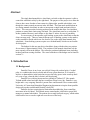
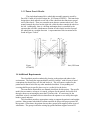
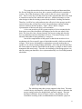
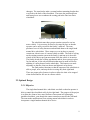
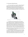
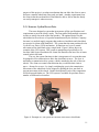
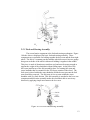
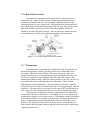
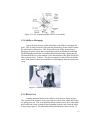
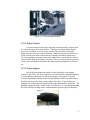
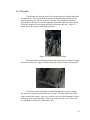
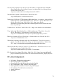
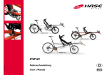
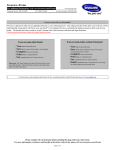
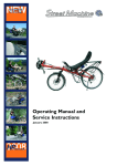
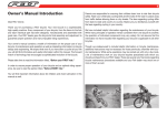
Final Report Single Hand Manual Drive Wheelchair Jordan R. Smith Kayla Gosse Leah McElhaney Team #5 Project for Client: Danielle Giroux Client Contact Information: Dave and Suzanne Giroux 53 Charlotte Dr, Tolland, CT 06084 [email protected] 860-604-0893 Table of Contents Abstract ……………………………………………………………………………….…………3 1 Introduction ……………………………………………………………………………………3 1.1 Background …………………………………………………………...………………3 1.2 Purpose of Project…………………………………………………………….…….…4 1.3 Previous Work Done by Others ………………………………………………………4 1.3.1 Products………………………………………………………………….…4 1.3.2 Patent Search Results ………………………………………………………5 1.4 Additional Requirements……………………………………………………………...6 2 Project Design …………………………………………………………………………………7 2.1 Introduction …………………………………………………………………………..7 2.2 Optimal Design ………………………………………………………………….…..9 2.2.1 Introduction…………………………………………………………….…..9 2.2.2 Conventional Folding Wheelchairs…………………………………….….10 2.2.3 Invacare Cyclical Lever Drive………………………………………….…11 2.2.4 Drive Arm Assembly…………………………………………………….…12 2.2.5 Fork and Steering Assembly…………………………………………….…13 2.2.6 Rear Wheel and Axle………………………………………………………14 2.2.7 Transmission…………………………………………………………….…14 2.2.8 Ability to Disengage……………………………………………………..…15 2.2.9 Wheel Lock…………………………………………………………………15 2.2.10 Wheel Braking………………………………………………………….…16 2.2.11 Safety Features……………………………………………………………17 2.2.12 Proper Support……………………………………………………………17 2.2.13 Detachable Seat………………………………………………………..…18 2.3 Prototype……………………………………………………………………………..18 2.3.1 Assembly of One Arm Drive System...…………………………...……….18 2.3.2 Seating Position………………………………………...………………….21 2.3.3 Foot rest……………………………………………………...…………….22 3 Realistic Constraints …………………………………………………………………………24 4 Safety Issues ……………………………………………………………………………….…25 5 Impact of Engineering Solutions ……………………………………………………………26 6 Life-Long Learning ………………………………………………………………………..…26 7 Budget and Timeline …………………………………………………………………………27 7.1 Budget………………………………………………………………………………..27 8 Team Members Contributions to the Project …………………………………………...…27 8.1 Team Member 1 …………………………………………………………………..…27 8.2 Team Member 2…………………………………………………………………...…28 8.3 Team Member 3 …………………………………………………………………..…28 9 Conclusion ……………………………………………………………………………………29 10 References …………………………………………………………………………………...29 11 Acknowledgements …………………………………………………………………………30 12 Appendix ………………………………………………………………………………….…31 12.1 Technical Specifications……………………………………………………………31 12.2 Relevant Links…………………………………………………………………...…31 2 Abstract The single hand manual drive wheelchair was built so that the operator is able to control the wheelchair solely by the right hand. The purpose of the project is to allow the client to have more freedom of movement in a lightweight, portable wheelchair, even though she cannot control movement in her left hand. The team made modifications to an existing manual wheelchair in order to incorporate a single hand mechanical drive device. The team researched existing products on the market that allow for wheelchair patients to control their chairs using one hand. The wheelchair must be no wider than 32 inches (standard doorway) and collapse to less than 12 inches for ease of portability. It was necessary to incorporate a safe braking system to the wheelchair so that the client can stop easily. There are many different types of braking systems on the market, so the team had to decide which one was best for use on the single hand manual drive wheelchair. Some braking systems require use with both hands, which was not feasible for this project. The budget for this one arm drive wheelchair, along with the other two projects for our team, is approximately $1000. The purchase of the manual wheelchair was the most expensive item in the budget. The team also purchased additional items including headrest and foam seating elements. The exact breakdown of the budget can be found in section 7.1. 1. Introduction 1.1 Background Danielle Giroux is an eleven year old girl living with cerebral palsy. Cerebral palsy is a condition that involves brain and nervous system functions. It is caused by injuries or abnormalities in the brain that occur as the baby grows in the womb up until two years of age, when the baby’s brain is still developing. Danielle lives with her parents and two siblings in Tolland, CT. She attends Tolland middle school and rides the bus to and from school every day. Danielle is very bright and is very outgoing. Danielle’s parents Dave and Suzanne Giroux contacted the University of Connecticut Biomedical Engineering department to inquire about possible design projects that could benefit Danielle’s daily life. Danielle also has certain physical limitations that inhibit her from controlling movement in her left hand. This limited motor control makes it difficult to propel and maneuver a manual wheelchair. The patient also recently had back surgery, which makes it difficult for her to cross her right arm over the rest of her body. 3 1.2 Purpose of the Project The purpose of this project is to design a more user-friendly wheelchair for our client who suffers from limited mobility. It is very difficult for the patient to move her manual wheelchair because she must make several movements with just one arm, crossing over her body to control the left side. The single hand manual wheelchair was designed so that it is functional using only the operator’s right hand. The patient uses a motorized wheelchair to move around her school, but the heaviness and bulkiness make it difficult for use within the home. Danielle and her family would like to use the manual wheelchair within the house or in other informal settings. Danielle and her family are worried about safety of this wheelchair. It is important that the wheelchair incorporate a braking system so that the patient can easily slow down and stop without hesitation. A quick braking system was applied to the wheelchair so that the patient can easily stop on command. The final product allows the patient to stop simply using her right hand. 1.3 Previous Work Done by Others 1.3.1 Products There is a product that is manufactured by Complete Medical called a One Arm Drive for Viper manual wheelchairs (model #10960RD), which is a replacement armrail mechanism that can be applied for patients who have limited mobility. Basically, this product is a replacement part in which the system can replace both wheels on an existing manual wheelchair. This product is sold for $256.36 online at http://makemeheal.com. Figure 1 below demonstrates this product. Figure 1: One Arm Drive for Viper manual wheelchair The company Southwest Medical specializes in a product line called Quickie Wheelchairs, along with a set of replacement parts to go along with their products. The company offers complete sets of one-arm drive replacements for 4 their wheelchairs. These complete sets can be purchased and modified to fit onto an existing Quickie Wheelchair. An example of these replacement kits can be found in Figure 2 below. It is possible for the group to find an existing set of onearm drive wheelchair parts, such as the one seen in Figure 2, and assemble them to an existing manual wheelchair. The price of this kit costs anywhere between $680 to $900, depending on the model of wheelchair. Figure 2: Replacement parts for one-arm drive It is necessary for the single hand manual wheelchair to have a braking mechanism so that the operator can easily stop. The company called ADI manufactures a set of disc brakes for manual wheelchairs that allow the user to simply push a lever to slow down. It’s called the Variable Lever Disc Brake system and is easily controlled with one hand only, compared to other systems that must be operated with both hands. Figure 3 below shows an operator applying the brake using the simple hand lever. A set of disc brakes surround the center of the wheel and when the hand brake is applied, the discs close to stop wheel movement. The price of this system was not listed on the manufacturer’s website, but can be approximated at about $250. Figure 3: ADI disc brake hand lever 5 1.3.2 Patent Search Results The single-hand manual drive wheelchair assembly patent is owned by David M. Counts of Quickie Designs Inc. (US Patent #5306035). This innovative design shows dual armrails on one side of the wheelchair that function to propel each of the wheels. These two armrails rotate about a common wheel axis. One armrail controls the wheel on the right side, while the other controls the wheel on the left. Additionally, there is a locking mechanism that is controlled by the operator that will allow simultaneous rotation of both wheels in order to propel the wheelchair in a straight direction. A representation of this invention can be found in Figure 5 below. Figure 4: Representation of Self-hand manual drive wheelchair (US Patent #5306035) 1.4 Additional Requirements The wheelchair must be aesthetically pleasing to the patient and others in her environment. The family has requested that it not look “robotic” with all sorts of metal contraptions, but that it has a soft feel and look to it. This will ensure comfort for the patient and so that it looks like any other standard wheelchair. Extra padding and covering shall be put in specific places to give a softer feel to the device. The team had to obtain their own manual wheelchair for this project. The specific model does not matter, as long as it is sturdy, collapses for the patient, and is able to fit through a doorway measuring no more than 32 inches wide. It is necessary for the wheelchair to have a mechanical device that allows the operator to use solely their right hand to propel and steer. The wheelchair must have appropriate seating to support the patient in and upright position. Many manual wheelchairs contain seats that do not provide proper posture for the operator. Often times, the patient does not have proper back support in these types of wheelchairs. The group would take existing hip guides and heat support from one of 6 Danielle’s wheelchairs and attach them to the single hand manual driven wheelchair. It was necessary for the group to keep in contact with Danielle’s physical therapist to ensure that the one arm drive wheelchair provided adequate support for the client. After discussing all of these constraints with the client, the team was able to create a chart detailing all of the specifications for this project. An outline of these quantitative specifications can be found in Appendix Section 12.1. 2 Project Design 2.1 Introduction The team has designed the single hand manual wheelchair for a client who does not have motor control in their left hand. The client has expressed a need for an easier way to navigate her wheelchair using only one hand, while still being able to control how fast it goes and which way it steers. There were three alternative designs that the team took into careful consideration when selecting the optimal design. The first design incorporated a one arm lever system that can be used in a pumping fashion to move the chair in forward and reverse directions with the turn of a switch. The client’s specifications called for a braking system to be built into the wheelchair so that the client can easily stop movement on command. The braking system involved with this design involves simply switching the gears into neutral and pulling back on the lever arm to stop movement. The second and third designs both incorporated a double-railed wheel setup on the right side of the wheelchair so that the client can propel the chair forward by spinning the rim associated with the respective wheel. There will be two rails on the right side--one rail controlling movement of the right wheel and another rail controlling movement of the left wheel. A gear box will allow the client to switch between control of a single wheel or control of both wheels in order to steer the wheelchair in different directions. The fall back of these designs is that a separate braking mechanism must be installed. Since the second and third alternative designs incorporated the same double-rail movement system, they had different braking mechanisms. The second design incorporated a set of disc brakes into the system that are similar to those in a motor vehicle. The disc brakes would be located within the rim of the wheel and around the axle. When the client applied the brakes, the discs would press against the wheel to cause friction in order to prevent movement. The third alternative design incorporated a set of hand brakes similar to what is seen on a standard bicycle. The hand brakes would function using a set of rubber pads that attach to a clamp around the tires. When the client desired to slow down or stop, they would squeeze a lever that would create tension in a wire connected to the brake pads. This would cause the clamp holding the brake pads to close, and the pads would create friction on the tire to prevent movement. 7 The group discussed these three alternative designs and determined that the first one using the one arm lever drive system would be best for a number of reasons. One of the advantages of this system is that it is easy to control and steer. There is only one lever that sticks out on the right side that allows the client to control movement of the wheelchair with ease. Another advantage over the other designs is that the existing system already includes a braking mechanism. Therefore, it will be less costly and more time effective for the group to use this system because they will not have to look into purchasing a separate braking system to attach to the final product. Figure 5 above shows a sample representation of this one arm drive lever mechanism. A lever one arm drive (OAD) system consists of a lever mounted to the front caster area of the wheelchair with linkages back to the rear wheel of the chair. The lever drive has a forward, neutral, and reverse setting and when the lever is pushed forward, the wheelchair will move. The neutral setting is used when the wheelchair is being pushed by a caregiver. One of the complications of this project is that the one arm drive lever mechanism only fits on specific types of wheelchair models, which are not built to collapse. There are no one hand drive mechanisms out on the market that are capable to use with an existing folding wheelchair. One of the specifications that the client requires is that the wheelchair has the ability to collapse so that it can be transported and stored easily. Therefore, the challenge of this design project is to take the existing one hand drive lever system and modify it to fit a folding manual wheelchair. Figure 5: One Arm Drive Lever System The wheelchair must have proper support for the client. The team worked closely with Danielle’s physical therapist in order to determine the proper seating position for adequate back and neck support. The team purchased a headrest, shown in Figure 6 below, and attached it to the wheelchair according to the recommendations from Danielle’s physical 8 therapist. The team had to make a custom headrest mounting bracket that was fixed to the back of the wheelchair. The team also purchased foam and foam glue to use to enhance the seating pad in the One Arm Drive wheelchair. Figure 6: Sample head rest for support The wheelchair must have proper restraint system for use in a motor vehicle. It is necessary for there to be straps in place so that the operator can be safely secured in the family’s minivan. The team purchased a set of safety harnesses and attached them to the single hand manual drive wheelchair. These straps were set in place to properly restrain our client in case of a motor vehicle accident. The team is relying on the existing restraint system in the family’s minivan to tie down the wheels of the chair to prevent movement while the vehicle is in motion. The family already has a lifting mechanism and tie down system in place for the minivan, so the only modification that must be made will be the addition of a safety harness on the wheelchair. This harness was made adjustable so that the client can loosen and tighten it at her desire. The final product functions so that the operator of the wheelchair is able to propel, steer, and stop the device using only their right hand. There are proper safety features in place to allow the chair to be stopped when desired and for safe use in a motor vehicle. 2.2 Optimal Design 2.2.1 Objective The single hand manual drive wheelchair was built so that the operator is able to control the wheelchair solely by the right hand. The purpose of the project is to allow the client to have more freedom of movement in a lightweight, portable wheelchair, even though she cannot control movement in her left hand. The team made modifications to an existing manual wheelchair in order to incorporate a single hand mechanical drive device. 9 2.2.2 Conventional Folding Wheelchairs There are many different types of wheelchairs, ranging from lightweight, portable, heavy-duty, manual, powered, folding, sport, and reclining. These different types all have benefits over others and are for use with a variety of different purposes. The type that the group used for this design was a conventional folding wheelchair for the sole purpose of being lightweight and portable. The client has specified that a folding manual wheelchair is necessary for this project so that the family can easily transport it from one place to the other. An example of a traditional folding wheelchair is shown in Figure 9 below. Figure 7: Example of a standard manual folding wheelchair A standard non-powered (manual) wheelchair must be controlled manually by two hands. There are two different types of manual wheelchairs, which are folding and non-folding. All standard manual wheelchairs have four wheels—two large in the back and two small in the front. The two front wheels are much smaller than the rear wheels and this is because they function for stability and are responsible for guiding the chair in the right direction when the operator makes a turn. The front wheels are able to swivel a full 360 degrees, while the rear wheels do not swivel at all. The purpose of the larger rear wheels is to allow movement of the wheelchair. Notice the large metal hand-rail in the sample wheelchair in Fig. 7. The operator must grab the hand-rail and rotate the wheels on the left and right sides of the wheelchair in order to allow the chair to move forward. The operator turns by simply stopping rotation of the wheel on the side of the wheelchair where they wish to turn. The client for this project does not have motor control in their left hand, which makes it very difficult to control movement on the left side of a standard manual wheelchair. This makes it extremely difficult for the client to propel the chair forward in a straight direction, or to steer to the left or right. The client normally uses her manual wheelchair within the home because it is easier to control in a smaller environment when compared to a power wheelchair. The 10 purpose of this project is to adapt a mechanism that can allow the client to move and steer a manual wheelchair using only one hand. Another requirement from the client is that the one hand drive wheelchair be able to fold so that the family can easily transport it when necessary. 2.2.3 Invacare Cyclical Lever Drive The team designed a system that incorporates all the specifications and requirements to meet the client’s needs. The team pulled from multiple resources in order to satisfy the needs of the final product. The optimal design for this wheelchair involves the use of a product manufactured by the Invacare Company. Invacare is a medical supply company that produces wheelchairs and wheelchair accessories for clients with disabilities. The system that the team purchased is the Cyclical Lever Drive (CLD) mechanism. It functions as a lever to control movement of the wheelchair using a single hand. Figure 8 below shows an example of the CLD system. This system is manufactured specifically to fit Invacare 9000 Series wheelchairs for clients like Danielle who have loss of motor control in their left hand. The way the system functions is that it incorporates a lever arm that must be pumped in a forward motion to allow the wheelchair to move. The lever is attached to a transmission drive system, which is attached to the axle of the rear wheels. The client can control what direction they would like their chair to move—forward or reverse—by simply switching the gear in the transmission. Movement of the wheelchair can be stopped by pulling the lever arm back to prevent movement of the wheels. Further description of each of the components will be discussed further on. The CLD system is available for purchase from a number of different local retailers. Figure 8: Example of CLD system for Invacare 9000 Series wheelchairs 11 One of the advantages of the CLD system is that it functions using only one hand. The purpose of this project is to design a system that can be applied to a standard manual wheelchair for the client to control using only their right hand. The CLD mechanism also has a built in braking system that functions to stop movement of the wheelchair upon command. This is one of the safety features that the client had recommended for the final product. There are also a few drawbacks to the CLD system as well. For instance, the system does not fit any standard manual wheelchair—it will only fit the Invacare 9000 Series wheelchairs, represented in Fig. 8. This made it a challenge for the team—the fact that they had to incorporate this system on any existing manual wheelchair. Another major drawback of the Invacare CLD system is that the online specifications did not indicate whether it could be applied to a folding wheelchair. The Invacare 9000 Series wheelchair products are standard manual wheelchairs, but do not collapse for easy portability. Therefore, the team was not able to use an Invacare 9000 Series wheelchair because it did not meet the specifications and needs of the client. The client has requested that the wheelchair be able to fold for easy transport and portability. The team was able to adapt a method to incorporate the CLD system onto a standard folding wheelchair. The most challenging portion of this project was designing a method for the existing single arm drive system to fit to any standard folding wheelchair. 2.2.4 Drive Arm Assembly The CLD system is broken down into many different components, each serving a purpose in the overall functionality of the wheelchair. The first major component is the arm assembly and Fig. 9 below shows a diagram of the basic setup. Basically, there is a two foot long handle that attaches to the fork of the front right wheel to control the steering and forward and reverse movements of the wheelchair. The drive arm functions as the main method of control for the client. The arm is moved back in forth in a pumping action in order to propel the wheelchair forward. With each pump, the lever system moves a set of gears attached to the axle, and this provides movement to the rear wheels. The arm is attached to the front wheel via a rotating mechanism, which allows the client to steer the direction of the wheelchair by turning the lever arm left or right. The client will also be able to adjust the height of the lever arm by simply unscrewing a nut that holds it in position. The lever arm will be able to slide up and down to the client’s desired height and can be securely tightened in place. This will allow the client to setup the arm assembly in a comfortable position in order to minimize discomfort while the wheelchair is in use. 12 Figure 9: CLD Drive Arm Assembly 2.2.5 Fork and Steering Assembly The second major component is the fork and steering mechanism. Figure 10 below shows a diagram of the basic fork and steering assembly. These components are responsible for holding together the drive arm and the front right wheel. The fork is a common part that attaches wheels because it has two prongs that go on each side of the wheel with an axle holding it together in the middle. This piece is made of aluminum or stainless steel and must be strong enough to support the weight of the wheelchair without falling apart. At the base of the drive arm (and the top of the fork assembly) there is a rotating fork stem and caster headtube that are essential for the 360 degree rotation of the wheel. The fork stem is placed within the caster headtube and the hex nut prevents the fork stem from being removed. The fork stem is free to rotate within the caster headtube with very little friction. This fork assembly is attached to the lever arm component and this entire assembly makes the wheelchair able to turn in any direction by applying simple movement to the lever arm. Figure 10: CLD Fork and Steering Assembly 13 2.2.6 Rear Wheel and Axle The third set of components of the one arm drive system are the rear wheels and axle. Figure 11 below shows a diagram representing how these components function as the lever arm is pumped. When the operator of the wheelchair desires to move forward, they will pump the lever arm and this will move the transmission assembly and transmission rear hub. The motion of these parts will essentially spin the rear wheel hub spokes and axle, which will ultimately spin the right and left wheels. The rear wheels are connected to the same rotating axle, so both wheels will rotate together at the same speed. Figure 11: CLD Rear Wheel and Axle Assembly 2.2.7 Transmission The transmission component of the wheelchair design is responsible for allowing the operator to change gears between forward, neutral, and reverse movement. This piece comes with the CLD system and is part of the lower portion of the lever arm. It basically attaches to the wheelchair side frame via a set of screws and this is what ultimately holds the control arm in place. The transmission functions using a small lever that protrudes out the top. This lever is accessible to the client on the right side of the wheelchair. There are three different gears as mentioned before—forward, neutral, and reverse. When the client desires to move in the forward direction, they will engage the gear using the small lever. The same process is necessary for moving in the reverse direction as well. Figure 12 below demonstrates the basic setup of the transmission system. One thing that is important to take into consideration is how difficult it is for the client to be able to switch gears. The shifting arm is a very simple setup and should not require a lot of energy to move. The pumping action of the control arm on the wheelchair is also another concern because it requires that the client make several pumping motions back and forth to move the wheelchair in any direction. The group has worked closely with the client to ensure that they are able to operate the wheelchair with ease and that it does not require a high degree of physical strain to use. 14 Figure 12: CLD Transmission and Gear Lever Assembly 2.2.8 Ability to Disengage One of the best features of this wheelchair is the ability to disengage the gears. This is really beneficial if the operator decides they do not want to control the wheelchair by themselves. This feature allows the ability for someone to disengage the gears so that they can manually push the wheelchair from behind. The disengaging mechanism is something that functions using a spring and pin. The bottom of the lever arm contains a piece that attaches to the front wheels like what is shown in Fig. 13 below. The pin can simply be removed from its holder on the front wheel to allow the wheelchair to be disengaged from the control arm setup. Figure 13: Ability to disengage CLD system 2.2.9 Wheel Lock Another important feature is the ability to lock the rear wheels in place. This is useful if the operator wants to prevent movement of the wheelchair if they are getting in or out. This is an important safety feature because if the wheelchair moves while the client is sitting down or standing up then it may cause the client to slip and get injured. The wheelchair locking mechanism is shown in Fig. 14 15 below. The functionality of this design allows a lever to be turned that presses a brake pad against the tires to prevent movement. This lever operates with a simple turn and can lock the wheel in place. There are two wheel locks--one for each side of the wheelchair to attach to the large rear wheels. The small front wheels do not have locking mechanisms. Figure 14: Ability to lock wheel in place 2.2.10 Wheel Braking Safety of the one arm drive wheelchair is a very important concern. The team took into account a braking mechanism that allows the client to easily stop the wheelchair on command. Some of the alternative designs discussed ideas about disc brakes and hand brakes for the one arm manual drive wheelchair. However, these ideas needed separate mechanical drive and braking mechanisms. The CLD system incorporates its own braking mechanism within the design. In order to apply the brakes, the operator simply pulls back on the arm drive lever. This motion can even be performed when the chair is in forward or reverse gears. An image representing the braking system and brake pads is shown in Fig. 15 below. When the operator pulls back on the lever arm, it presses the brake bad against the rubber tire, which hinders movement of the wheels. The advantage of using this system is that there are very little mechanical pieces or wires sticking out. If the team were to incorporate a hand brake system similar to that seen in bicycles, there would be many metal wires sticking out and running from the front to the back of the wheelchair. The existing system shown in Fig. 15 eliminates all these wires and large contraptions and keeps the design relatively simple. 16 Figure 15: CLD braking mechanism 2.2.11 Safety Features It was necessary for the team to take into account the safety features used in a restraint system for a motor vehicle. The client’s minivan already has the necessary wheelchair tie downs for the wheels. The team had to design the buckle system for the seat on the wheelchair. Both the front and rear wheels are safely secured to the floor of the minivan so that the wheelchair cannot move. The team attached a restraint system to the wheelchair to ensure that the client is secured while riding in the family’s minivan. There is a strap that goes across the client’s chest and lap that will buckle into place just like a standard seat belt in a car. 2.2.12 Proper Support One of the most important features of this wheelchair is the support system for the client. The team worked closely with Danielle’s physical therapist to ensure that the wheelchair provides proper posture and support. The team invested in padding including a head rest and additional foam seat cushioning so that they can ensure the client gets the support she needs. Figure 16hows an example of a headrest that was applied to the single hand manual wheelchair. The headrest is approximately 8 inches wide by 5 inches tall. It was positioned behind the client’s head according to the recommendations from her physical therapist. Figure 16: Example of headrest 17 2.2.13 Detachable Seat One of the most important features of the single hand drive manual wheelchair is the ability of it to fold for easy portability and storage. This task is very difficult with all the support padding in place, so the team designed a seat that can be easily removed. This chair will be set into the wheelchair and will contain all the necessary padding and support. The chair will not be able to fold when the seat is in place. Once the seat is removed from the wheelchair, it will be able to collapse. 2.3 Prototype 2.3.1 Assembly of One Arm Drive System After developing an optimal design for the One Arm Drive wheelchair, the team began assembling a prototype for our client. The team started making the prototype by first purchasing the Invacare Cylindrical Lever Drive (CLD) System from NEAT Marketplace. The team was able to get this part for about $50, which is much cheaper than the cost of purchasing a new system online. This device functions to move the wheelchair forward by simply performing a pumping action of the right hand. Figure 17 below shows an image of the one arm drive system that we purchased. Figure 17: Invacare Cylindrical Lever Drive System The team also purchased a standard folding wheelchair from NEAT Marketplace to be used for attachment of the Invacare Cylindrical Lever Drive System. This is just a standard folding wheelchair that has been previously owned. It has been cleaned and tested by the NEAT Marketplace staff to ensure that it is safe for others to use. Figure 18 below shows an image of the wheelchair that we purchased. 18 Figure 18: Standard wheelchair purchased from NEAT Marketplace In order to fold this wheelchair, it’s necessary to remove the backrest and the seat padding so that it can collapse. There are a set of pins in the backrest that must be removed from their slots in order for the part to be separated from the rest of the wheelchair. The seat cushion is simply fixed in placed with two strips of Velcro. The seat padding was modified to match the physical needs of the client and the design of this part can be seen later on in the report. The team was able to attach the Invacare Cylindrical Lever Drive system to the right side of the wheelchair. This device operates by simply moving the lever arm forward in a pumping motion. The transmission contains a gearbox that allows the client to change between forward, neutral, and reverse movements. The operator simply changes the gear depending on which direction they would like to move. Pumping the arm will cause the chair to move in the direction specified. Figure 19 shows the completed assembly of the lever drive system to the standard folding wheelchair. Figure 19: Assembly of the lever drive system to wheelchair The operator can also control the steering of the One Arm Drive wheelchair by turning the lever arm to the right or left. The lever arm is directly attached to the front right wheel of the wheelchair and positioning of this wheel determines which direction the chair will turn. The height of this lever arm is 19 adjustable so that it can be specifically tailored to the client’s preferred height. After attaching the one arm drive lever system to the folding wheelchair, the team was able to shift their primary focus on the proper seating position and safety features of the wheelchair. 2.3.2 Seating Position The team was able to focus their attention on making sure the one arm drive wheelchair provided proper support to the client. The team met with Matt Luginbuhl at PediaFlex, who is Danielle’s physical therapist, in order to get recommendations about the proper seating position of the wheelchair. The team purchased a headrest, seating pad, and foot rest at NEAT Marketplace that would all be used as seating support elements for the wheelchair. During the team’s session with Matt, they were able to get advice on where to enhance the foam support padding in the seat. Matt was able to take several measurements of Danielle’s body and the team even let her test out the wheelchair for the first time. She was very excited to test out the prototype and she seemed to be able to operate the wheelchair with ease. Though her movement of the wheelchair was not perfect on this initial trial, she will certainly get better at maneuvering her wheelchair once she has time to practice. Figure 20 below shows our client, Danielle, with her physical therapist testing out the One Arm Drive wheelchair for the very first time. Figure 20: Danielle and her physical therapist testing out OAD wheelchair After getting the dimensions of our client’s body, the team was able to purchase high density foam and foam glue that can be used to enhance the seating support in the seat cushion. The team cut the foam into several strips and glued it to the existing foam seat cushion. The black outer cover to the seat cushion was still able to fit around the outside in order to enclose all of the foam pieces. The sides of the seat cushion, in addition to the front-middle section, were all areas 20 where additional foam padding was added. Figure 21 shows the custom seating pad in the One Arm Drive Wheelchair. Figure 21: Custom seating pad enhanced with foam The purpose of this additional padding is to keep Danielle’s hips properly aligned while sitting in the wheelchair. The folding wheelchair that the team purchased is meant for a fully grown adult and was a little big for our client. The placement of this foam padding compensates for the size of the wheelchair and provides a better fit and better support for our client. The team also determined the exact height necessary for the headrest. It was necessary to make a custom headrest bracket in the machine shop that will act to hold the headrest in place while the wheelchair is in use. The custom headrest bracket was made so that it can attach to the back of the wheelchair. There is a small aluminum piece that fits the headrest support rod through it and a bolt can be tightened to hold it in place. This allows the headrest to be vertically adjustable so that it can fit the client perfectly. Figure 22 below shows the custom headrest bracket that the team made in the machine shop. Figure 22: Custom headrest bracket for wheelchair 21 2.3.3 Foot Rest The placement of the One Arm Drive system interferes with the right foot rest placement. The way the footrest attaches to the wheelchair interferes with how the operator uses the One Arm Drive system. The team had to develop a method for the footrest to reach the right side of the wheelchair from the left side. The team designed a footrest plate that folds out from the left side. Figure 23 below shows this footrest in the folded position. Figure 23: Footrest in folded position The team added an aluminum plate to make the footrest extend to the right side of the wheelchair. Figure 24 below shows the footrest in the useful position. Figure 24: Footrest in useful position The team was able to bolt this extended aluminum piece to the existing left foot rest so that the system folds out at normal. The team filed down all the edges so that it isn’t sharp. Also, a set of holes were cut in the aluminum to allow foot straps to be weaved through. These foot straps are made out of Velcro and are adjustable to fit the size of the client’s feet. 22 2.3.4 Safety Features There are also a number of safety features that are included in the One Arm Drive wheelchair. The first safety feature is the addition of a braking feature. This braking features functions to stop the movement of the wheelchair when the lever arm is pulled all the way back. The operator simply pulls back on the drive arm to stop movement of wheelchair. There is a brake pad that rests against the right wheel and prevents further movement of the wheelchair. The wheelchair also features a wheel locking system that prevents movement while client gets in and out. This is to be used to prevent movement of the wheels. The One Arm Drive wheelchair can also be used on incline surfaces, as demonstrated by one of our lab partners in Figure 25 below. Figure 25: Leah tests the One Arm Drive wheelchair on incline 23 3 Realistic Constraints There are many physical constraints that come into play with the design of this single hand manual drive system. For example, it was necessary for the team to consider the realistic constraints associated with the economic, environmental, sustainability, manufacturability, ethical, social, political, and health and safety concerns. The team must make sure that this design is feasible and that the final product is beneficial for the client without hindering their safety or wasting money. The group took economic concerns into consideration when designing the single hand manual drive wheelchair. The purpose of the project was to make a wheelchair that can be fully functional using only the right hand. However the group did not want to design a product that will be way too expensive. In other words, it is necessary that the costs don’t outweigh the benefits. In industry, engineers design products, but they will not sell if the production costs are too high. The company would simply lose money out of the manufacturing of the product. The same concept applies to our single hand manual drive wheelchair. Another constraint that the team faces is the environmental impacts of the wheelchair. The team did not use any motorized components, so they are not worried about pollutants that could be harmful to the environment. The team must be careful with what types of materials they are using and what kind of impact they will have on the environment. If the team were using dangerous chemicals to construct the wheelchair, then there would be serious impacts on the environment and safety of the client and team members. However, the team did not use any potentially dangerous chemicals or pollutants in the fabrication of this product, so it is not necessary to be particularly concerned about the impact on the environment. The manufacturability of the product is a large concern that the team had to take into consideration when designing the wheelchair. The team did not want to design something that would be extremely difficult to produce or hard to use. The design should be kept as simple as possible, and consideration into every detail was critical to ensure that the final product would be successful. The constraints of the project were within reason. This was important so that the team was not trying to build something that was close to the impossible. The feasibility of the project is something that is critical both in the senior design course and in real world industry. The sustainability of the product is very important as well because the team did not want to create something that will fall apart after a short period of use. The final product should be strong and sturdy and able to support years of use without falling to pieces. The group was sure to double check all mechanical parts on the wheelchair before turning it over to the client to make sure that everything is safe and that bolts and screws are tightened in place. Should the unexpected happen and something to go wrong, the group provided an instruction manual for the client to perform simple repairs and preventative maintenance. The social concerns have to do with how the client interacts with her environment and the people around her. The client has specified that the wheelchair not look so robotic and that special padding or paint be used to cover large protruding parts if necessary. The team kept the mechanical parts within reason so that the wheelchair does not stand out in the client’s environment. The family would like the wheelchair to look 24 like any other ordinary wheelchair to not draw a large amount of attention. The group also does not want to design something that will be too difficult for the client to use in her environment. The lever arm system must be a very simple design so that the client can control it with ease. If the lever arm were too difficult to use, it would defeat the purpose of making the wheelchair to begin with. Health and safety concerns are by far the most important aspect of the single arm manual wheelchair design. The team took many precautions into consideration when designing the final product to ensure complete operator safety. The first safety component is the use of seat restraints. These can be used for when the client is in a motor vehicle so that they properly restrain her in case of a motor vehicle accident. Another health and safety component is the seating position in the wheelchair. The team worked closely with the client’s physical therapist to ensure the head rest and seat were positioned correctly so that they do not harm the client’s health. The third health and safety concern is the ability to stop the wheelchair. The chair has a built in braking mechanism so that the operator can simply pull back on the one arm drive mechanism to stop the wheelchair. The last safety feature is the ability to lock the wheels. This will be useful if the client is getting into or out of the wheelchair and will prevent the wheelchair from moving during the process. 4 Safety Issues The team took into account many safety and health concerns when designing the one arm drive manual wheelchair. For example, many of the possible safety concerns that were necessary to address were components that have to do with electronics, mechanical pieces, biological hazards, decontaminants, chemical hazards, radiation, thermal factors, biocompatibility, and host reaction to materials. Fortunately, there are no materials in this project that are being inserted into the human body, so the team does not need to worry about biocompatibility and how the body will react to foreign substances. There are also no electrical concerns associated with this project because the team did not include any electronics in the design of the one arm drive manual wheelchair. However, there are always potential safety concerns with the mechanical pieces of the wheelchair and the possibility of someone pinching their hand or fingers in a moving component. The concerns are very minimal with the design of this single hand manual drive wheelchair, but it should be noted that it is always possible for it to happen. The team has addressed this issue by using an existing one hand manual drive system that has already been tested against these types of hazards. The rotating mechanical pieces are located underneath the wheelchair and are out of the way from any potential hazard. In order for someone to pinch their fingers, they would literally have to have their hand under the wheelchair while it is in use. Therefore, the chances of injury are very low due to mechanical components based on the location of the moving pieces under the wheelchair. The team had to be careful with what types of materials were used for the wheelchair. The team had to make sure they weren’t using anything that was radioactive or conducted a lot of thermal energy, or that could be dangerous in any other way to the 25 client. Again, the client’s health and safety is the number one concern for this project. The team used standard metals like aluminum, steel, or titanium that are strong and reliable and are harmless to the client in terms of chemical or radioactive exposure. 5 Impact of Engineering Solutions The engineering solution to this problem is not an extremely difficult matter. The team took an existing product out on the market and adapted it to fit the client’s purposes. The global impact to the engineering solution is that the world might see a new way to design the traditional manual wheelchair. Manual wheelchairs have always been made to operate with two hands, but it’s possible that in the future they will be designed similar to the one the team is building for Danielle. The world could see a change in how wheelchairs function in order to provide client’s like Danielle with an easier way to get around. This type of design does not have any long term influences on the economy. If the design were ever put into industry, it may perhaps be modified in the future to be less costly to produce. This would allow the company to make more money by keeping production costs low and market value high. This design has very little environmental impacts because it does not contain any radioactive or toxic chemicals that may degrade or corrode to have a negative impact on the environment. The wheelchair was made from steel or aluminum components that do not have any negative impacts on the environment. The team would have to take precautions if they were working with hazardous materials that could cause potential safety and health implications. The overall societal influence that this design has is very small in terms of the entire society. However, if we were to take into account the difference that it makes to the client, the impact that it has on her ability to interact with society is phenomenal. 6 Life-Long Learning The team has learned a lot through the design of the one hand manual drive wheelchair. Before beginning this project, the team never knew that such a system existed on the market. The group has been explored many different braking options and has learned the difference between hand brakes and disc brakes based on how they function. Both types are made to stop movement of the wheels to slow down the wheelchair’s speed, but they work differently in many ways. Disc brakes are more difficult to apply to this type of wheelchair when compared to hand brakes. The downside is that hand brakes are harder for the client to use. The team was able to find a system that allows the arm drive and braking system to be combined together for easy use. The brake system acts similar to hand brakes where there is a brake pad that rubs against the tire to prevent movement. However, since it is incorporated into the hand drive mechanism, it is easier to use because all that must be done is that the operator pulls back on the arm drive when they desire to slow down. The most important thing the team has learned about is the condition of cerebral palsy and what sort of implications it has on the client’s mobility. The team is helping to improve the life of someone with disabilities through the design of the single hand drive manual wheelchair. 26 7 Budget 7.1 Budget For the single hand manual drive wheelchair, the group purchased their own portable wheelchair to use and make modifications to. It was possible to find one of these wheelchairs used at NEAT Marketplace in Hartford, CT, for approximately $65. The team used the Cylindrical Lever Drive System manufactured by Invacare. They were able to assemble this drive system to the lightweight wheelchair in order to ensure that it can be controlled using one arm. The team spent about $50 on the lever drive system. It’s also necessary to take into consideration costs of seat support. The headrest and foot rest parts were purchased from NEAT Marketplace for about $10. It was necessary to make a headrest holding bracket and to extend the footrest, which cost about $10 in aluminum. The team also needed to purchase foam and foam glue for the modification of the seat cushion, which cost about $10. These additional parts were included in our budget. Table 1 below represents a total budget of $145 for the single hand manual drive wheelchair. Table 1: Estimated budget for single hand manual drive wheelchair Item Cost Lightweight Folding Wheelchair $65 One Arm Drive System $50 Headrest/Footrest $10 Misc. Parts (foot straps, aluminum, foam, glue, etc.) $20 Total $145 8 Team Members Contributions to the Project 8.1 Team Member 1 Our first team member, Jordan, contributed to this project by visiting the client at her home in Tolland and discussing the specifications of the project with her and her family. Jordan also was responsible for writing one of the three alternative designs, as well as most of the reports for the one arm drive wheelchair throughout the semester. Our entire team, including Jordan, went to NEAT Marketplace in Hartford to purchase all 27 the wheelchair parts and accessories. Figure 24 below shows pictures of the wheelchair and one arm drive system that were purchased from NEAT. The team was able to attach the one arm drive to the right side of the wheelchair and next semester they will focus on the proper seating position. Jordan has been responsible for keeping in close contact with the client’s physical therapist and also making sure the team’s website is up to date. Jordan also was involved with meeting the client’s physical therapist and discussing the proper seating position of the one arm drive wheelchair. Both Jordan and Leah made the headrest bracket that holds the headrest in the proper position on the back of the wheelchair. Figure 24: Wheelchair frame and complete one arm drive assembly 8.2 Team Member 2 Our second team member, Leah, contributed to this project by visiting the client at their home in Tolland to discuss the project specifications with her and her family. Leah also contributed by creating the second of three alternative designs for the one arm drive wheelchair. She also created most of the Solidworks diagrams for the alternative and optimal designs. Leah was able to come to NEAT marketplace with the rest of the team to purchase the wheelchair and accessories. The most extensive part of this project involved attachment of the one arm drive to the wheelchair. Leah was responsible for most of the work involved with the assembly of these components. Leah also contributed by helping to make the footrest modifications. She provided insight on how to attach the foot straps to the wheelchair and was responsible for cutting the holes in the foot rest plate to weave the straps through. Lastly, Leah and Jordan both worked on creating the custom headrest bracket in the machine shop. 8.3 Team Member 3 Our third team member, Kayla, was responsible for also going to NEAT marketplace to pick up wheelchair parts and accessories and visiting the client at her home in Tolland. Kayla came up with the third alternative design for this project and was responsible for creating Solidworks diagrams to show how the 28 wheelchair will operate. Kayla also worked on the assembly of the one arm drive component to the wheelchair frame. She contributed by keeping our budget up to date and was responsible for researching different safety restraint systems fir the one arm drive wheelchair. Kayla also contributed by visiting the physical therapist, collecting materials, and adding all the necessary foam to the wheelchair seating pad. She is responsible for all of the seat padding that was added to the seat cushion for support for the client. 9 Conclusion The completed single arm manual drive wheelchair functions to provide the patient with an accessible way to maneuver her wheelchair with one hand and with ease. The finished product incorporates several safety features, including a braking system and safety harnesses for travel in a motor vehicle. The wheelchair is able to easily collapse for portability and it is lightweight. This product is different than any other product out on the market because it contains several modifications to existing manual wheelchairs. There is a mechanical one-arm device that allows movement with a single hand. The final product is also able to stop on command with the incorporation of a braking system. Additionally, the wheelchair is patient-specific because it includes specific padding and support to allow proper posture. 10 References "CLD: Cylindrical Lever Drive (9000 Wheelchairs)." Web. 9 Dec. 2011. <http://www.invacare.com/doc_files/1087937.pdf>. "Fold Up Chairs | FoldupTables." Folding And Multi-purpose Table. Web. 09 Dec. 2011. <http://folduptables.co.uk/category/folup-chair/>. "Invacare Cylindrical Lever Drive." Web. 9 Dec. 2011. <http://www.phconline.com/v/vspfiles/docs/CLD-lever.pdf>. "Lowrider Rear Hand Brake Kit." Bike Parts to Make Bicycles Look Good. Custom Bicycles and Custom Bike Parts for Designers. Bicycle Parts That Work with Lowrider Bicycles and Cruiser Bicycles and Chopper Bicycles and Trikes. Web. 09 Dec. 2011. <http://www.bicycledesigner.com/bike-parts/lowrider-rear-hand-brake-kit.html>. "One Arm Drive Right for Viper & Viper GT Wheelchairs, Complete Medical, 10960RD." Plastic Surgery Recovery, Cosmetic Surgery, Anti Aging Skin Care, Message Board, Product. Web. 09 Dec. 2011. <http://www.makemeheal.com/mmh/product.do?id=102831>. 29 "One Arm Drive Right for Viper & Viper+GT Wheelchairs, Complete Medical, 10960RD." Plastic Surgery Recovery, Cosmetic Surgery, Anti Aging Skin Care, Message Board, Product. Web. 09 Dec. 2011. <http://www.makemeheal.com/mmh/product.do?id=102831>. "One Arm Drive Systems." Mobility Basics. Web. 9 Dec. 2011. <http://mobilitybasics.com/onearmdrives.htm>. "Quickie Iris (S/N Prefix CGT) Replacement Wheelchair Parts - Accessories - One-Arm Drive (S/N Preifx CGT) - Quickie-Wheelchairs.com." Welcome to Quickie-Wheelchairs.com Quickie-Wheelchairs.com. Web. 09 Dec. 2011. <http://www.quickiewheelchairs.com/wheelchair-parts/sunrise-medical/quickie-iris/accessories/one-armdrive-s-n-preifx-cgt>. "Variable Lever." ADI Rides. Web. 09 Dec. 2011. <http://www.adirides.com/variable.html>. "Viper Lightweight Wheelchair by Drive | 1800wheelchair.com." Wheelchair: Manual & Electric Wheelchairs | 1800wheelchair.com. Web. 09 Dec. 2011. <http://www.1800wheelchair.com/asp/view-product.asp?product_id=1470>. Wheelchair: Manual & Electric Wheelchairs | 1800wheelchair.com. Web. 09 Dec. 2011. <http://www.1800wheelchair.com>. "Wheelchair Positioning Adjustable Angle Hip Guide Hardware." Therafin Corporation -Quality, Cost Effective Wheelchair Seating and Positioning Solutions. Web. 09 Dec. 2011. <http://www.therafin.com/adjustableanglehipguidehardware.htm>. "Wheelchair Rider Risk in Motor Vehicles: A Technical Note." Rehabilitation Research & Development Service. Web. 09 Dec. 2011. <http://www.rehab.research.va.gov/jour/00/37/1/shaw.htm>. WPI: One Arm Drive Manual Wheelchair. Web. 9 Dec. 2011. <http://www.wpi.edu/Pubs/Eproject/Available/E-project-043009-105716/unrestricted/Wheelchair_MQP_0809.pdf>. 11 Acknowledgements Dr. Enderle: Design advice and guidance Marek: Design advice and guidance Giroux Family: Provided design ideas to benefit Danielle NEAT Marketplace- Don: Assistance in finding parts Matt Luginbuhl at Pediaflex: Danielle’s Physical Therapist Pete and Serge: Provided advice and materials Jennifer Desrosiers Jim Gosse 30 12 Appendix 12.1 Technical Specifications Physical: Type of Wheelchair: Model: Dimensions: Number of Tiedowns: Safety Harnesses: Type of OAD System: Attachment: Mechanical (Wheelchair): Size: Weight: Speed: Power: Mechanical (One Arm Drive): Weight: System Capacity: Mechanism Color: Installation: Added width to chair: Environmental: Operating Environment: Safety: Manual Wheelchair Invacare 9000 Series 30” wide by 45” deep by 36” high 4 (2 Front, 2 Back) Yes Invacare Cylindrical Lever Drive Right Side Width less than 32”, able to collapse Approximately 30 lbs User defined Non-powered 9.1 lbs 250 lbs black/chrome right or left hand 1.5 in Indoor/Outdoor Tie-downs to secure wheelchair to vehicle Vest support to secure patient to wheelchair Simple braking mechanism Maintenance: Easily fixed if malfunctions Allows room for growth Able to be transported Able to collapse 31 12.2 Related Links The following are related links that show more information about the Invacare CLD mechanism: ● Invacare CLD Product information: http://www.phc-online.com/v/vspfiles/docs/CLD-lever.pdf ● Invacare CLD Product Manual: http://www.invacare.com.au/ass/content/930/966/poirier-user-manual-aus.pdf ● Video demonstrating use of CLD system: http://www.youtube.com/watch?v=eGkV5apxcvs ● Local Invacare vendors: http://www.invacare.com/cgi-bin/imhqprd/inv_dealer/dealer_results.jsp?s=0 ● Invacare CLD system for sale online: http://www.phc-online.com/CLD_LEVER_DRIVE_LH_6_INSTALL_p/inv-ldr96li.htm 32